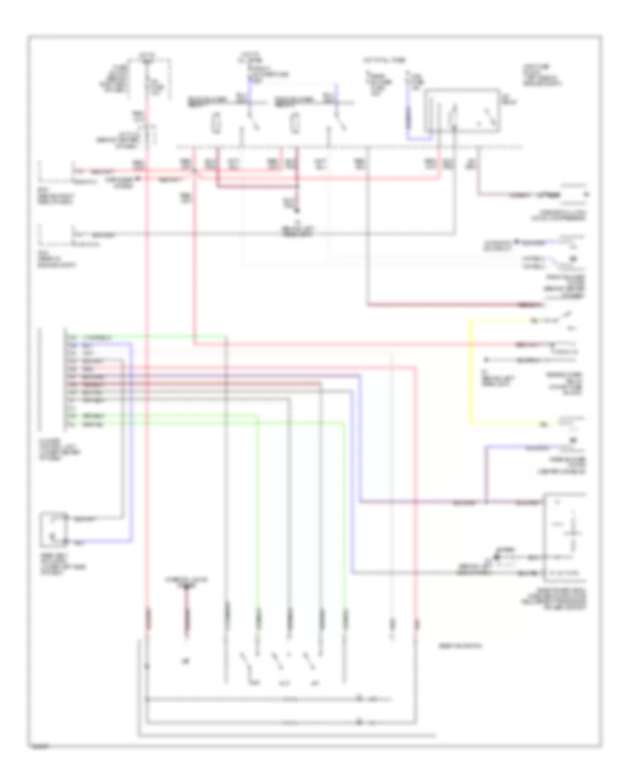
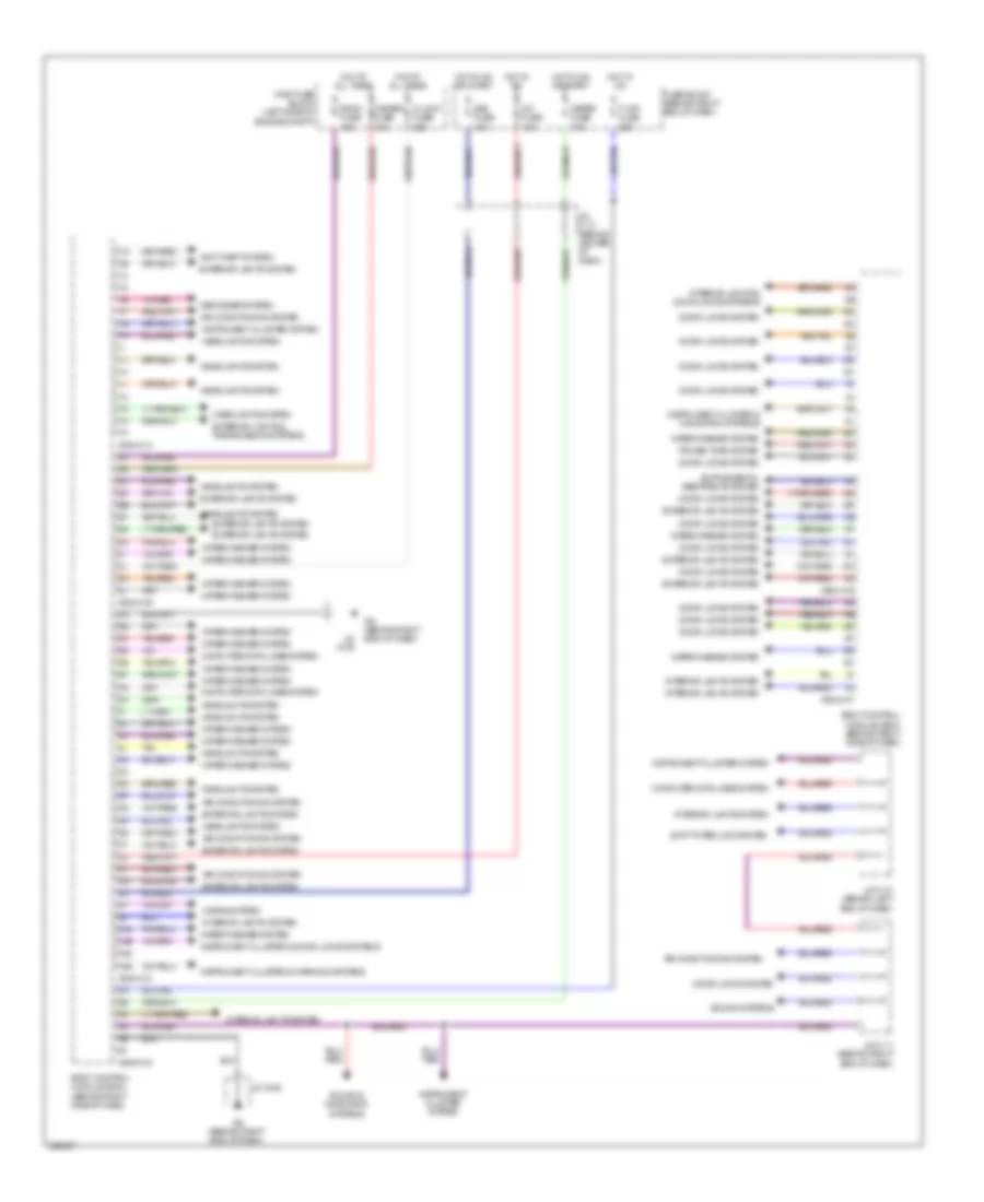
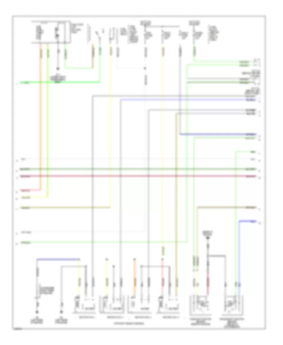
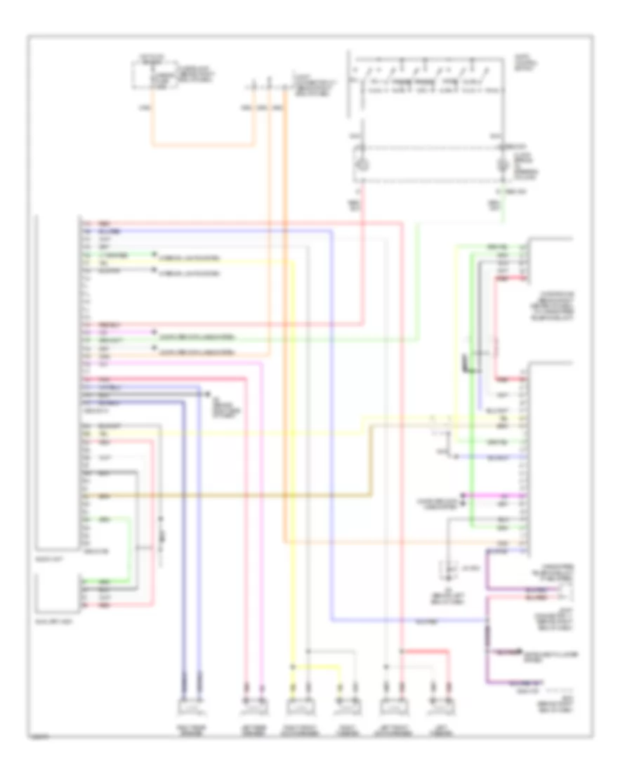
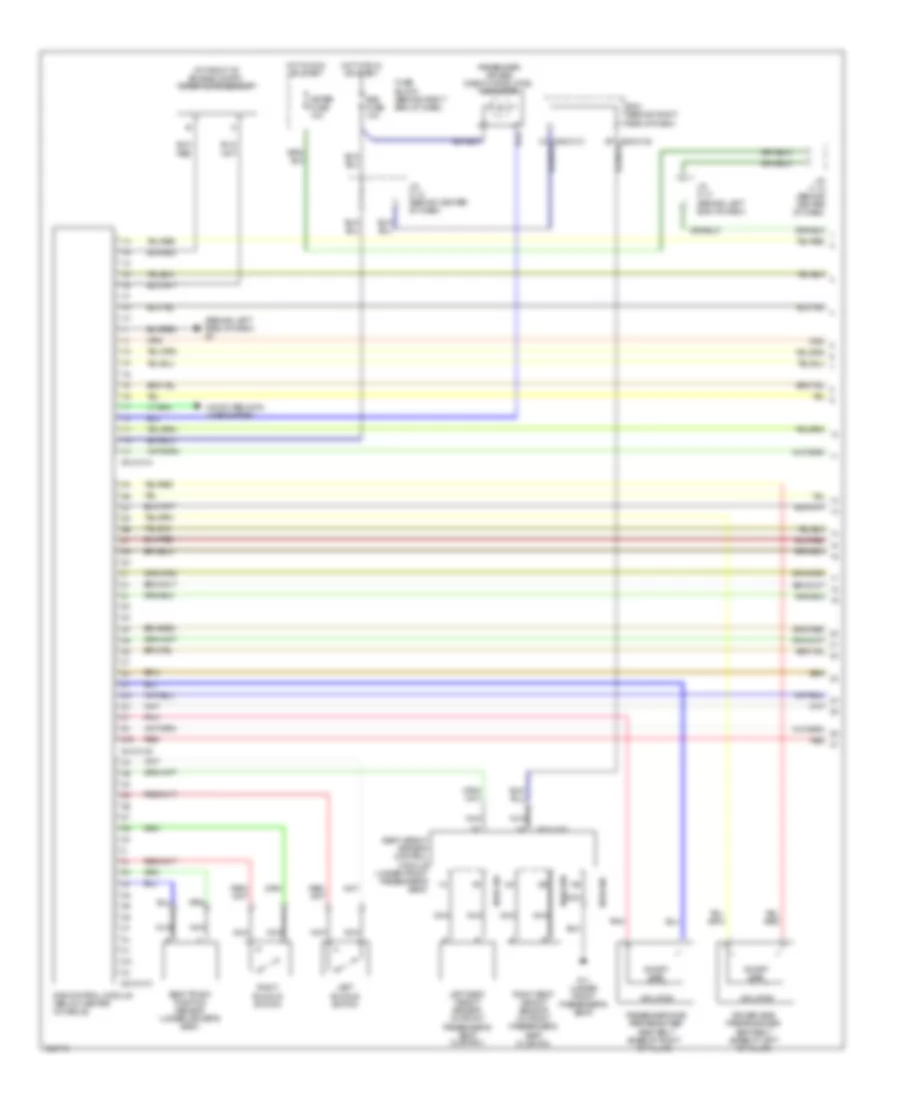
AIR CONDITIONING
Automatic A/C Wiring Diagram for Mazda 5 Grand Touring 2010

List of elements for Automatic A/C Wiring Diagram for Mazda 5 Grand Touring 2010:
- (behind center of dash) passenger compartment temperature sensor
- 0112-01a
- 0112-01b
- 0140-101a
- 0140-101b
- 0940-01a
- 0940-01d
- 1aw
- 1ax
- 2ah
- 2av
- A/c fuse 10a
- A/c relay
- Air intake actuator (behind right side of dash)
- Air mix actuator (behind right center of dash)
- Airflow mode actuator (behind left center of dash)
- Ambient temperature sensor (behind center of grille)
- Bcm (behind right side of dash)
- Blower fuse 40a
- Blower relay (in main fuse block)
- Climate control unit (lower center of dash)
- Cold
- Computer data lines system
- Cooling fan motor
- Cooling fan relay
- Def
- Defogger system
- Eng fuse 5a
- Engine coolant temperature sensor (top rear of engine)
- Evaporator temperature sensor (under center of dash)
- Fan control module (left front of engine compt)
- Fan fuse 30a
- Front blower motor (behind center of dash)
- Front power metal oxide semiconductor field effect transistor (power mos fet) (behind center of dash)
- Fuse block (behind right end of dash)
- G1 (behind left headlight)
- G4 (behind left end of dash)
- G6 (behind right end of dash)
- High & low pressure
- Hot
- Hot at all times
- Hot in run
- Hot in run or start
- Interior lights system
- J/c c-11 (behind right end of dash)
- J/c c-12 (behind center of dash)
- Jc-g04
- Jc-g06
- Mag fuse 10a
- Magnetic clutch (on a/c compressor)
- Main fuse block (left side of engine compt)
- Medium pressure
- Nca
- Pcm (powertrain control module) (rear of engine compt)
- Red
- Refrigerant pressure switch (right rear of engine compt)
- Solar radiation sensor (under top center of dash)
- Vent
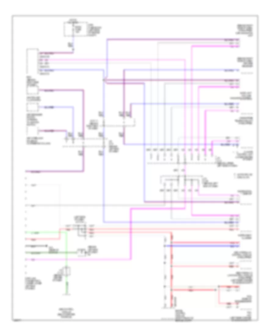
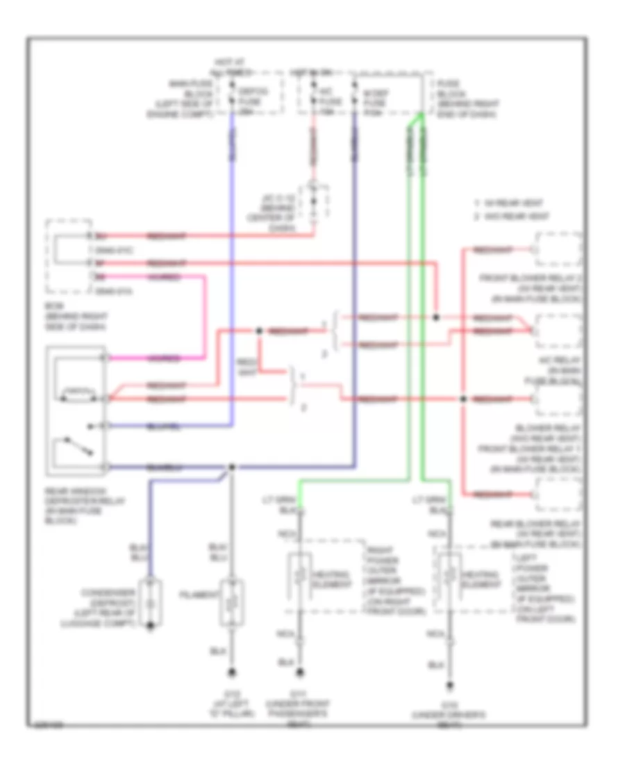
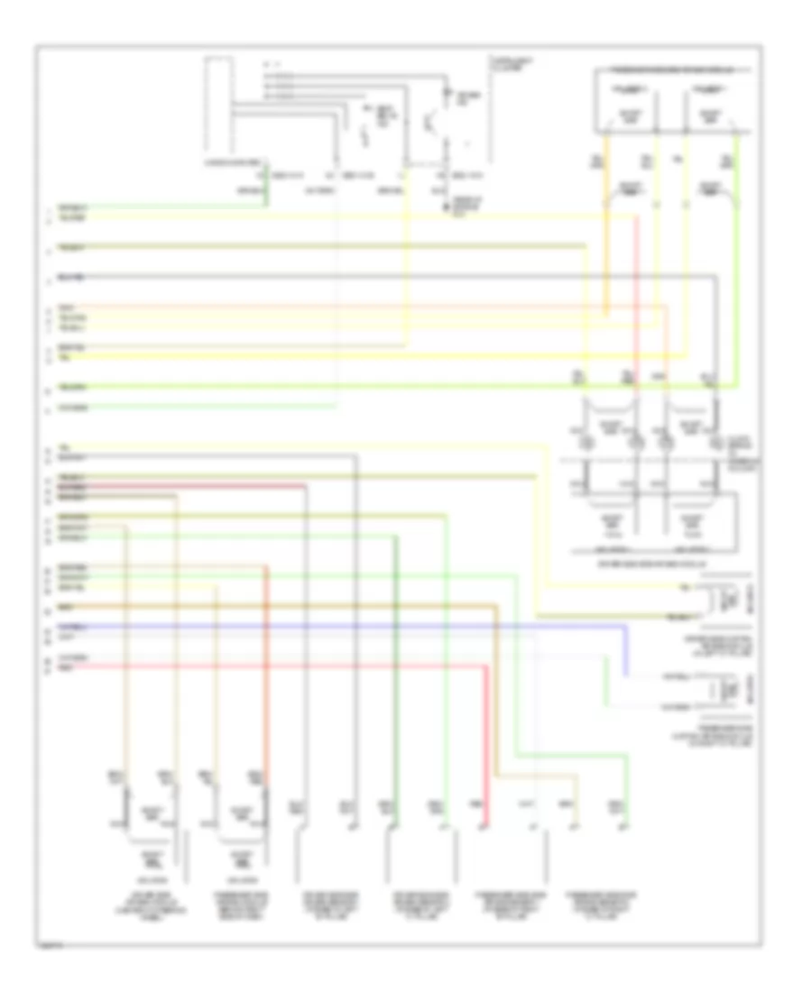
Rear A/C Wiring Diagram for Mazda 5 Grand Touring 2010
List of elements for Rear A/C Wiring Diagram for Mazda 5 Grand Touring 2010:
- 0140-101a
- 0940-01a
- A/c fuse 10a
- A/c relay
- Automatic a/c circuit
- Bcm (behind right side of dash)
- Climate control unit (lower center of dash)
- Defogger system
- Front blower fuse 20a
- Front blower motor (behind center of dash)
- Front blower relay 1
- Front blower relay 2
- Fuse block (behind right end of dash)
- G1 (behind left headlight)
- G4 (behind left end of dash)
- Hot at all times
- Hot in run
- Interior lights system
- J/c c-12 (behind center of dash)
- Jc-g04
- Mag fuse 10a
- Magnetic clutch (on a/c compressor)
- Main fuse block (left side of engine compt)
- Nca
- Off
- Pcm (rear of engine compt)
- Rear blower fuse 30a
- Rear blower motor (center console)
- Rear blower relay (in main fuse block)
- Rear fan switch
- Rear power metal oxide semiconductor field effect transistor (power mos fet)
- Rear vent actuator (lower left side of dash)
- Red
ANTI-LOCK BRAKES
Anti-lock Brakes Wiring Diagram, with Dynamic Stability Control for Mazda 5 Grand Touring 2010
List of elements for Anti-lock Brakes Wiring Diagram, with Dynamic Stability Control for Mazda 5 Grand Touring 2010:
- (left front of engine compt) g3
- (on left front wheel assembly)
- (rear of engine) g14
- 0614-01c
- 0922-101a
- 4wd abs ind
- Abs p fuse 30a
- Abs v fuse 20a
- Abs/ dsc fuse 5a
- Combined sensor (base of right "b" pillar)
- Computer data lines system
- Computer micro-
- Dsc hydraulic unit/ control module (dsc hu/cm)
- Dsc off switch
- Ehpas control module (right front of engine compt)
- Fuse block (behind right end of dash)
- G1 (behind left headlight)
- G4 (behind left end of dash)
- Hot at all times
- Hot in on or start
- Instrument cluster
- J/c c12 (behind center of dash)
- J/c c31 (behind left end of dash)
- J/c g04
- Left front abs wheel speed sensor
- Left rear abs wheel speed sensor (on left rear wheel assembly)
- Main fuse block (left side of engine compt)
- Meter fuse 10a
- Pnk
- Red
- Right front abs wheel speed sensor (on right front wheel assembly)
- Right rear abs wheel speed sensor (on right rear wheel assembly)
- Steering angle sensor (in steering column)
Anti-lock Brakes Wiring Diagram, without Dynamic Stability Control for Mazda 5 Grand Touring 2010
List of elements for Anti-lock Brakes Wiring Diagram, without Dynamic Stability Control for Mazda 5 Grand Touring 2010:
- (behind left headlight) g1
- (on left front wheel assembly)
- 0922-101a
- 4wd abs ind
- Abs hydraulic unit/control module (left rear corner of engine compt)
- Abs p fuse 30a
- Abs v fuse 20a
- Abs/dsc fuse 5a
- Computer data lines system
- Computer micro-
- Fuse block (behind right end of dash)
- G14 (rear of engine)
- Hot at all times
- Hot in on or start
- Instrument cluster
- J/c c12 (behind center of dash)
- J/c c31 (behind left end of dash)
- Left front abs wheel speed sensor
- Left rear abs wheel speed sensor (on left rear wheel assembly)
- Main fuse block (left side of engine compt)
- Meter fuse 10a
- Red
- Right front abs wheel speed sensor (on right front wheel assembly)
- Right rear abs wheel speed sensor (on right rear wheel assembly)
ANTI-THEFT
Forced Entry Wiring Diagram for Mazda 5 Grand Touring 2010
List of elements for Forced Entry Wiring Diagram for Mazda 5 Grand Touring 2010:
- (at left "d" pillar)
- (at left rear "c" pillar) left rear slide door switch
- (at right rear "c" pillar) right rear slide door switch
- 0922-101b
- 0940-01a
- 0940-01c
- 0940-01e
- 0940-01f
- 2j 0940-01b
- 3ab
- Bcm (behind right side of dash)
- Computer data lines system
- D lock fuse 20a
- Door key cylinder switch/ door lock-link switch/ left front door latch switch/ left front door lock actuator (in driver's door)
- Door lock relay
- Door unlock relay
- Double lock relay
- Fuse block (behind right end of dash)
- G10 (under driver's seat)
- G11 (under front passenger's seat)
- G12
- G12 (at left "d" pillar)
- G13 (at right "d" pillar)
- G2 (behind right headlight)
- G4 (behind left end of dash)
- Hood latch switch (on hood latch assembly)
- Horns system
- Hot at all times
- Hot in on or start
- Instrument cluster
- J/c c-12 (behind center of dash)
- J/c-g04
- Keyless receiver (behind right side of dash)
- Left door lock switch
- Left rear door lock-link switch
- Left sliding door lock actuator (in left sliding door)
- Liftgate latch switch (on liftgate latch)
- Liftgate lock actuator (in liftgate)
- Lock
- Main fuse block (left side of engine compt)
- Meter fuse 10a
- Nca
- Reset
- Right door lock switch
- Right front door latch switch/ right front door lock actuator (in front passenger's door)
- Right rear door lock-link switch
- Right sliding door lock actuator (in right sliding door)
- Set
- Un- lock
- Unlock
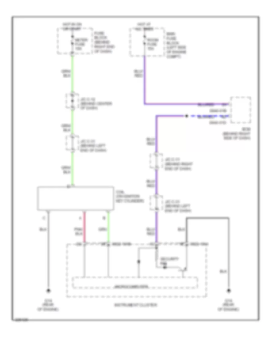
Immobilizer Wiring Diagram for Mazda 5 Grand Touring 2010
List of elements for Immobilizer Wiring Diagram for Mazda 5 Grand Touring 2010:
- 0922-101a
- 0922-101b
- 0940-01b
- 0940-01d
- Bcm (behind right side of dash)
- Coil (on ignition key cylinder)
- Fuse block (behind right end of dash)
- G14 (rear of engine)
- Hot at all times
- Hot in on or start
- Instrument cluster
- J/c c-11 (behind right end of dash)
- J/c c-12 (behind center of dash)
- J/c c-31 (behind left end of dash)
- Main fuse block (left side of engine compt)
- Meter fuse 10a
- Microcomputer
- Room fuse 15a
- Security ind
BODY CONTROL MODULES
Body Control Modules Wiring Diagram for Mazda 5 Grand Touring 2010
List of elements for Body Control Modules Wiring Diagram for Mazda 5 Grand Touring 2010:
- 0940-01a
- 0940-01b
- 0940-01c
- 0940-01d
- 0940-01e
- 0940-01f
- 3aa
- 3ab
- 3ac
- 3ad
- A/c fuse 10a
- Air conditioning system
- Anti-theft system
- Body control module (bcm) (behind right side of dash)
- Computer data lines system
- D lock fuse 20a
- Defogger system
- Door locks system
- Exterior lights & transmission systems
- Exterior lights system
- F wip fuse 25a
- Fuse block (behind right end of dash)
- G6 (behind right end of dash)
- Hazard fuse 10a
- Headlights system
- Horns system
- Hot at all times
- Hot in on
- Hot in on or start
- Instrument cluster & door locks systems
- Instrument cluster & navigation systems
- Instrument cluster & warning systems
- Instrument cluster system
- Interior lights & door locks systems
- Interior lights system
- J/c c-11 (behind right end of dash)
- J/c c-12 (behind center of dash)
- J/c c-31 (behind left end of dash)
- J/c g-06
- Main fuse block (left side of engine compt)
- Meter fuse 10a
- Power tops system
- Room fuse 15a
- Sas fuse 10a
- Shift interlock system
- Sound & navigation systems
- Sound systems
- Wiper/washer system
COMPUTER DATA LINES
Computer Data Lines Wiring Diagram for Mazda 5 Grand Touring 2010
List of elements for Computer Data Lines Wiring Diagram for Mazda 5 Grand Touring 2010:
- (behind left end j/c g-04
- (behind right side of dash) (if equipped) car navigation unit
- (behind right side of dash) keyless receiver
- (left side of dash) j/c c-44
- 0614-01b
- 0940-01b
- 0940-01c
- 0940-01d
- 1ai
- 1am
- Abs hydraulic unit/control module (if equipped) (left rear corner of engine compt)
- Audio unit (w/o car- navigation system)
- Automatic a/c
- Bcm (behind right side of dash)
- Climate control unit (lower center of dash)
- Data link connector 2 (under lower left end of dash)
- Dsc hydraulic/ control module (if equipped)
- Ehpas control module (right front of engine compt)
- G14 (rear of engine)
- Hands-free telephone unit (if equipped)
- Hot at all times
- Ignition key illumination
- Information display
- Instrument cluster
- J/c c-11 (behind right end of dash)
- J/c c-12 (behind center of dash)
- J/c c-13 (behind upper left side of dash)
- J/c c-31 (behind left end of dash)
- J/c c-38 (behind left end of dash)
- Key interlock solenoid (in steering column)
- Key reminder switch (integral to ignition switch)
- Main fuse block (left side of engine compt)
- Manual a/c
- Of dash) g4
- Pcm (rear of engine compt)
- Pnk
- Red
- Room fuse 15a
- Sas control module (below center console)
- Tcm (a/t) (left rear corner of engine compt)
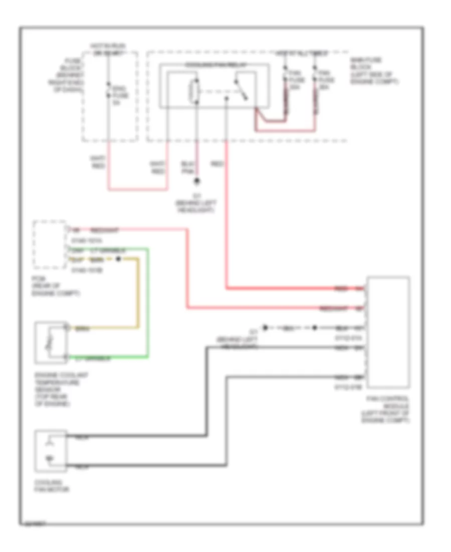
COOLING FAN
Cooling Fan Wiring Diagram for Mazda 5 Grand Touring 2010
List of elements for Cooling Fan Wiring Diagram for Mazda 5 Grand Touring 2010:
- 0112-01a
- 0112-01b
- 0140-101a
- 0140-101b
- 2ah
- 2av
- Cooling fan motor
- Cooling fan relay
- Eng fuse 5a
- Engine coolant temperature sensor (top rear of engine)
- Fan control module (left front of engine compt)
- Fan fuse 30a
- Fuse block (behind right end of dash)
- G1 (behind left headlight)
- Hot at all times
- Hot in run or start
- Main fuse block (left side of engine compt)
- Nca
- Pcm (rear of engine compt)
- Red
CRUISE CONTROL
Cruise Control Wiring Diagram for Mazda 5 Grand Touring 2010
List of elements for Cruise Control Wiring Diagram for Mazda 5 Grand Touring 2010:
- (amber) cruise ind
- (green) cruise ind
- (rear of engine) g14
- 0140-101a
- 0140-101b
- 0922-101a
- 0922-101b
- 0922-202
- 0922-203
- 1ai
- 1al
- 1am
- 1ao
- 1ap
- 1aq
- 1av
- 1bc
- 1bd
- 2ak
- 2al
- 2ao
- 2ap
- 2be
- 2bf
- Accelerator pedal position sensor (top of accelerator pedal assembly)
- Brake switch 2 (at top of brake pedal assembly)
- Cancel switch
- Clock spring (in steering column)
- Clutch pedal position switch (m/t) (top of clutch pedal assembly)
- Computer data lines system
- Cruise control main switch
- Cruise control switch
- Eng bar 2 fuse 15a
- Fuse block (behind right end of dash)
- G10 (under driver's seat)
- G14 (rear of engine)
- Hot in run or start
- Hot w/ main relay energized
- Instrument cluster
- J/c c-12 (behind center of dash)
- J/c c-31 (behind left end of dash)
- J/c c-34
- Main fuse block (left side of engine compt)
- Meter fuse 10a
- Microcomputer
- Nca
- Neutral switch (m/t) (on transaxle)
- Pcm (rear of engine compt)
- Red
- Resume/accel switch
- Set/coast switch
- Tcm (left rear corner of engine compt)
- Throttle body (integral to throttle body)
- Vehicle speed sensor (a/t) (on transaxle)
DEFOGGERS
Defoggers Wiring Diagram for Mazda 5 Grand Touring 2010
List of elements for Defoggers Wiring Diagram for Mazda 5 Grand Touring 2010:
- 0940-01a
- 0940-01c
- A/c fuse 10a
- A/c relay (in main fuse block)
- Bcm (behind right side of dash)
- Blower relay (w/o rear vent) front blower relay 1 (w/ rear vent) (in main fuse block)
- Condenser (defrost) (left rear of luggage compt)
- Defog fuse 25a
- Filament
- Front blower relay 2 (w/ rear vent) (in main fuse block)
- Fuse block (behind right end of dash)
- G10 (under driver's seat)
- G11 (under front passenger's seat)
- G12 (at left "d" pillar)
- Heating element
- Hot at all times
- Hot in on
- J/c c-12 (behind center of dash)
- Left power outer mirror (if equipped) (on left front door)
- M def fuse 7.5a
- Main fuse block (left side of engine compt)
- Nca
- Rear blower relay (w/ rear vent) (in main fuse block)
- Rear window defroster relay (in main fuse block)
- Right power outer mirror (if equipped) (on right front door)
- W/ rear vent
- W/o rear vent
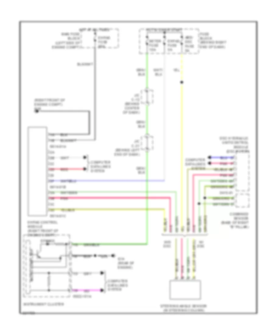
ELECTRONIC POWER STEERING
Electronic Power Steering Wiring Diagram for Mazda 5 Grand Touring 2010
List of elements for Electronic Power Steering Wiring Diagram for Mazda 5 Grand Touring 2010:
- (right front of engine compt) g16
- 0415-01
- 0614-01a
- 0614-01b
- 0614-01c
- 0922-101a
- Abs/ dsc fuse 5a
- Combined sensor (base of right "b" pillar)
- Computer data lines system
- Dsc hydraulic unit/control module (dsc hu/cm)
- Ehpas control module (right front of engine compt)
- Ehpas fuse 5a
- Ehpas fuse 80a
- Eps ind
- Fuse block (behind right end of dash)
- G14 (rear of engine)
- Hot at all times
- Hot in on or start
- Instrument cluster
- J/c c-12 (behind center of dash)
- J/c c-31 (behind left end of dash)
- Main fuse block (left side of engine compt)
- Meter fuse 10a
- Micro computer
- Pnk
- Red
- Steering angle sensor (in steering column)
- W/ dsc
- W/o dsc
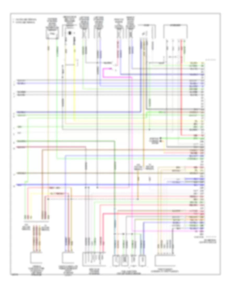
ENGINE PERFORMANCE
2.3L
2.3L, Engine Performance Wiring Diagram (1 of 4) for Mazda 5 Grand Touring 2010
List of elements for 2.3L, Engine Performance Wiring Diagram (1 of 4) for Mazda 5 Grand Touring 2010:
- (at top of brake pedal assembly) brake switch 1
- 0140-101a
- 1aa
- 1ab
- 1ac
- 1ad
- 1ae
- 1af
- 1ag
- 1ah
- 1ai
- 1aj
- 1ak
- 1al
- 1am
- 1an
- 1ao
- 1ap
- 1aq
- 1ar
- 1as
- 1at
- 1au
- 1av
- 1aw
- 1ax
- 1ay
- 1az
- 1ba
- 1bb
- 1bc
- 1bd
- 1be
- 1bf
- 1bg
- 1bh
- Air conditioning system
- Clutch pedal position switch (m/t) (top of clutch pedal assembly)
- Computer data lines system
- Cruise control system
- Exterior lights system
- G10 (under driver's seat)
- G14 (rear of engine)
- Hot at all times
- Main fuse block (left side of engine compt)
- Nca
- Neutral switch (m/t) (on transaxle)
- Pnk
- Powertrain control module (rear of engine compt)
- Red
- Starting/charging system
- Stop fuse 10a
2.3L, Engine Performance Wiring Diagram (2 of 4) for Mazda 5 Grand Touring 2010
List of elements for 2.3L, Engine Performance Wiring Diagram (2 of 4) for Mazda 5 Grand Touring 2010:
- (at right "d" pillar) g13
- (rear of engine) g14
- 0922-101a
- 0922-101b
- Accelerator pedal position sensor (top of accelerator pedal assembly)
- Check engine ind
- Computer data lines system
- Drive-by-wire relay (etc relay)
- Eng b + fuse 10a
- Eng ba fuse 20a
- Eng bar 2 fuse 15a
- Eng bar fuse 15a
- Etc fuse 10a
- Evap system leak detection pump (under rear of vehicle)
- Fuel fuse 20a
- G14 (rear of engine)
- Hot at all times
- Instrument cluster
- Joint connector c-34
- Main fuse block (left side of engine compt)
- Main relay (egi main relay)
- Mass air flow/ intake air temperature sensor (rear of engine)
- Micro- computer
- Pnk
- Red
2.3L, Engine Performance Wiring Diagram (3 of 4) for Mazda 5 Grand Touring 2010
List of elements for 2.3L, Engine Performance Wiring Diagram (3 of 4) for Mazda 5 Grand Touring 2010:
- (rear of engine) g14
- (top right side of engine)
- Camshaft position sensor (rear of engine)
- Condenser (right rear of engine)
- Crankshaft position sensor (above a/c compressor)
- Eng 2 fuse 15a
- Eng 3 fuse 20a
- Eng fuse 5a
- Fuel gauge sender unit
- Fuel pump
- Fuel pump relay
- Fuel pump unit (on fuel tank)
- Fuse block (behind right end of dash)
- G11 (under front passenger's seat)
- G5 (left rear of engine)
- Hall ic
- Hot in on or start
- Igniter
- Ignition coil 1
- Ignition coil 2
- Ignition coil 3
- Ignition coil 4
- J/c c-12 (behind center of dash)
- J/c c-31 (behind left end of dash)
- Main fuse block (left side of engine compt)
- Meter fuse 10a
2.3L, Engine Performance Wiring Diagram (4 of 4) for Mazda 5 Grand Touring 2010
List of elements for 2.3L, Engine Performance Wiring Diagram (4 of 4) for Mazda 5 Grand Touring 2010:
- (behind drive belt auto tensioner) knock sensor
- (front of engine) oil control valve
- (left side of engine) variable intake air solenoid valve
- (left side of engine) variable tumble solenoid valve
- (or red)
- (rear of engine compt) purge solenoid valve
- (top rear of engine) engine coolant temperature sensor
- 0140-101b
- 2aa
- 2ab
- 2ac
- 2ad
- 2ae
- 2af
- 2ag
- 2ah
- 2ai
- 2aj
- 2ak
- 2al
- 2am
- 2an
- 2ao
- 2ap
- 2aq
- 2ar
- 2as
- 2at
- 2au
- 2av
- 2aw
- 2ax
- 2ay
- 2az
- 2ba
- 2bb
- 2bc
- 2bd
- 2be
- 2bf
- 2bg
- 2bh
- A/f sensor
- Egr valve (top rear of engine)
- Fuel injectors (top left side of engine)
- Ho2s
- Manifold absolute pressure sensor (front of engine compt)
- Nca
- Pnk
- Powertrain control module
- Red
- Starting/ charging system
- Throttle body (integral to throttle body)
- Variable tumble shutter valve switch (left rear of engine)
- W/ pcm 2ae terminal
- W/ pcm 2as terminal
- W/ pcm 2bg terminal
- W/o pcm 2ae terminal
- W/o pcm 2as terminal
- W/o pcm 2bg terminal
EXTERIOR LIGHTS
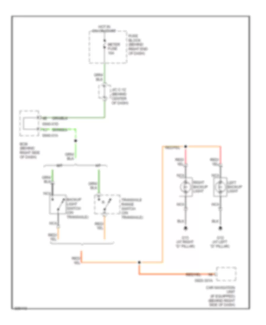
Backup Lamps Wiring Diagram for Mazda 5 Grand Touring 2010
List of elements for Backup Lamps Wiring Diagram for Mazda 5 Grand Touring 2010:
- 0920-301a
- 0940-01a
- 0940-01d
- A/t
- Backup light switch (on transaxle)
- Bcm (behind right side of dash)
- Car navigation unit (if equipped) (behind right side of dash)
- Fuse block (behind right end of dash)
- G12 (at left "d" pillar)
- G13 (at right "d" pillar)
- Hot in on or start
- J/c c-12 (behind center of dash)
- Left backup light
- M/t
- Meter fuse 10a
- Nca
- Right backup light
- Transaxle range switch (on transaxle)
Exterior Lamps Wiring Diagram for Mazda 5 Grand Touring 2010
List of elements for Exterior Lamps Wiring Diagram for Mazda 5 Grand Touring 2010:
- (behind left end of dash)
- 0140-101a
- 0922-101a
- 0940-01b
- 0940-01c
- 0940-01e
- 1ab
- Auto
- Bcm (behind right side of dash)
- Brake switch (at top of brake pedal assembly)
- Computer data lines system
- Flash- to- pass
- Fuse block (behind right end of dash)
- G1 (behind left headlight)
- G12 (at left "d" pillar)
- G13 (at right "d" pillar)
- G14 (rear of engine)
- G2 (behind right headlight)
- G4 (behind left end of dash)
- Hazard fuse 10a
- Hazard warning switch
- Head light
- Headlight switch
- High mount brake light
- Hot at all times
- Hot in on or start
- Instrument cluster
- J/c c-12 (behind center of dash)
- J/c c-31 (behind left end of dash)
- J/c-g04
- Jc-g04
- Left brake light
- Left front turn/ parking light
- Left license plate light
- Left rear turn light
- Left taillight
- Left turn ind
- Main fuse block (left side of engine compt)
- Meter fuse 10a
- Micro computer
- Nca
- Off
- Park
- Pcm (rear of engine compartment)
- Red
- Right brake light
- Right front turn/ parking light
- Right license plate light
- Right rear turn light
- Right taillight
- Right turn ind
- Selector lever component (in center console)
- Stop fuse 10a
- Tail fuse 10a
- Tns
- Tns relay
- Turn
- Turn switch
- W/ autolamps
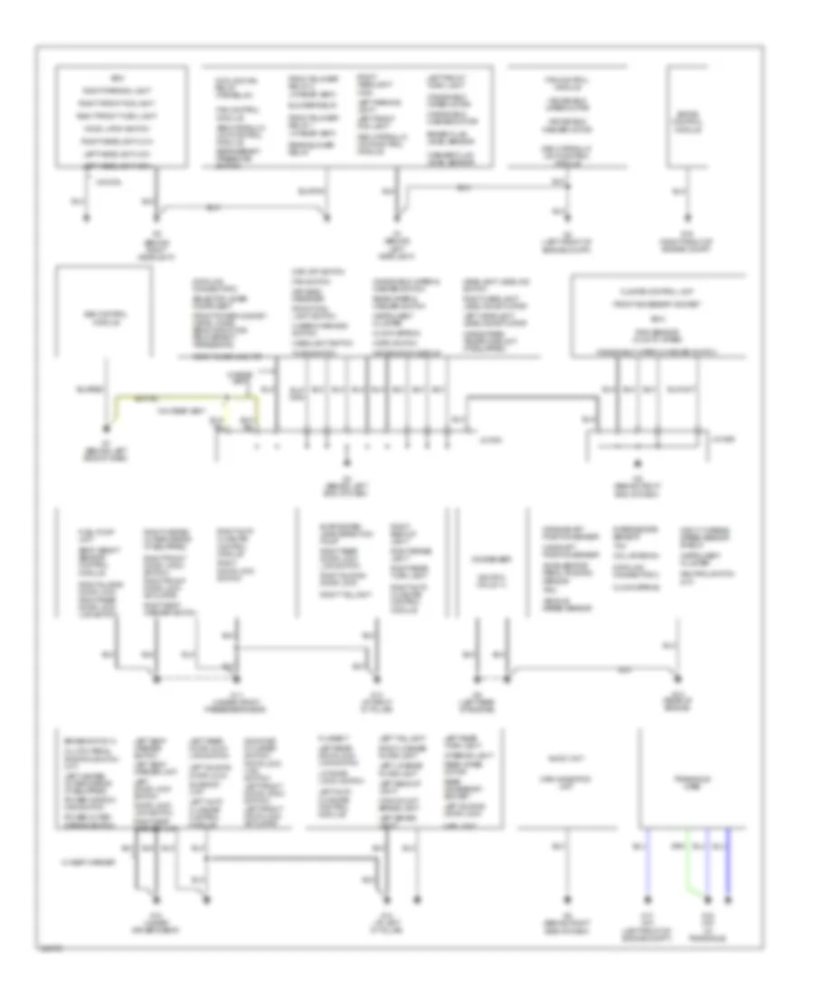
GROUND DISTRIBUTION
Ground Distribution Wiring Diagram for Mazda 5 Grand Touring 2010
List of elements for Ground Distribution Wiring Diagram for Mazda 5 Grand Touring 2010:
- (behind right headlight)
- Abs hydraulic unit/control module
- Accelerator pedal position sensor
- Audio unit
- Bcm
- Blower relay
- Brake fluid level sensor
- Brake switch 2
- Camshaft position sensor
- Car-navigation unit
- Climate control unit
- Clock spring
- Clutch pedal position switch (m/t)
- Coil antenna
- Condenser
- Cooling fan relay (fan relay)
- Crankshaft position sensor
- Data link connector 2
- Door key cylinder switch/ door lock link switch/ left front door latch switch/ left front door lock actuator
- Door lock link switch
- Dsc hydraulic unit/control module
- Dsc off switch
- Ehpas control module
- Evap system leak detection pump
- Fan control module
- Fan switch
- Filament
- Front accessory socket
- Front blower relay 1 (w/ rear vent)
- Front blower relay 2 (w/ rear vent)
- Front fog light switch
- Front power mos fet (metal oxide semiconductor field effect transistor)
- Fuel pump unit
- G1 (behind left headlight)
- G10 (under driver's seat)
- G11 (under front passenger's seat)
- G12 (at left "d" pillar)
- G13 (at right "d" pillar)
- G14 (rear of engine)
- G15 (a/t) (in transaxle)
- G16 (right front of engine compt)
- G17 (a/t) (left front of engine compt)
- G3 (left front of engine compt)
- G4 (behind left end of dash)
- G5 (left rear of engine)
- G6 (behind right end of dash)
- G7 (behind left side of dash)
- G8 (behind right side of dash)
- Hands-free telephone unit (if equipped)
- Hazard warning switch
- Headlight leveling switch
- Headlight switch
- High mount brake light
- Hood latch switch
- Horn switch
- Ignition coils 1-4
- Information display
- Input/ turbine speed sensor shield
- Instrument cluster
- Interior light
- Intermediate sensor
- J/c-g04
- J/c-g06
- Keyless receiver
- Left auto closure control module
- Left backup light
- Left brake light
- Left door lock switch
- Left front fog light
- Left front turn light
- Left headlight high
- Left headlight leveling actuator
- Left headlight low
- Left heated outer mirror (if equipped)
- Left license plate light
- Left parking light
- Left rear door lock link switch
- Left rear turn light
- Left seat warmer switch
- Left seat warmer unit
- Left sliding door lock
- Left taillight
- Liftgate latch switch
- Map light
- Neutral switch (m/t)
- Pcm
- Power outer mirror switch
- Power window main switch
- Rain sensor (w/ auto wiper)
- Rear accessory socket
- Rear blower relay
- Rear power mos fet
- Rear wiper & washer switch
- Rear wiper motor
- Refrigerant pressure switch
- Right auto closure control module
- Right backup light
- Right brake light
- Right door lock switch
- Right front door latch switch/ right front door lock actuator
- Right front fog light
- Right front turn light
- Right headlight high
- Right headlight leveling actuator
- Right headlight low
- Right heated outer mirror (if equipped)
- Right license plate light
- Right parking light
- Right rear door lock link switch
- Right rear turn light
- Right seat warmer switch
- Right seat warmer unit
- Right sliding door lock
- Right taillight
- Sas control module
- Seat weight sensor control module
- Selector lever component
- Sunroof unit
- Tcm
- Transaxle case
- Turn switch
- Vehicle speed sensor
- W/ rear vent
- W/ seat warmer
- W/o drl
- W/o rear vent
- Washer fluid level sensor
- Windshield washer motor
- Windshield wiper & washer switch
- Windshield wiper motor
HEADLIGHTS
Headlights Wiring Diagram for Mazda 5 Grand Touring 2010
List of elements for Headlights Wiring Diagram for Mazda 5 Grand Touring 2010:
- (rear of engine) g14
- 0922-101a
- 0940-01a
- 0940-01b
- 0940-01c
- 0940-01d
- 0940-01e
- Auto
- Bcm (behind right side of dash)
- Computer data lines system
- Computer micro
- Discharge type
- Flash- to- pass
- Fog fuse 15a
- Front fog light relay (in main fuse block)
- Front fog light switch
- Fuse block (behind right end of dash)
- G1 (behind left headlight)
- G2 (behind right headlight)
- G4 (behind left end of dash)
- Halogen type
- Head
- Head high l fuse 10a
- Head high r fuse 10a
- Head low l fuse 15a
- Head low r fuse 15a
- Headlight high relay
- Headlight low relay
- Headlight switch
- Hi-beam ind
- Hot at all times
- Hot in on or start
- Instrument cluster
- Instrument cluster system
- Interior lights system
- J/c-12 (behind center of dash)
- J/c-31 (behind left end of dash)
- Jc-g04
- Left discharge headlight control module
- Left front fog light
- Left high headlight
- Left low head- light
- Left low headlight
- Main fuse block (left side of engine compt)
- Meter fuse 10a
- Off
- Parking brake switch (at base of parking brake lever)
- Red
- Right discharge headlight control module
- Right front fog light
- Right high headlight
- Right low headlight
- Tns
- W/ autolamps
- W/ drl
- W/o drl
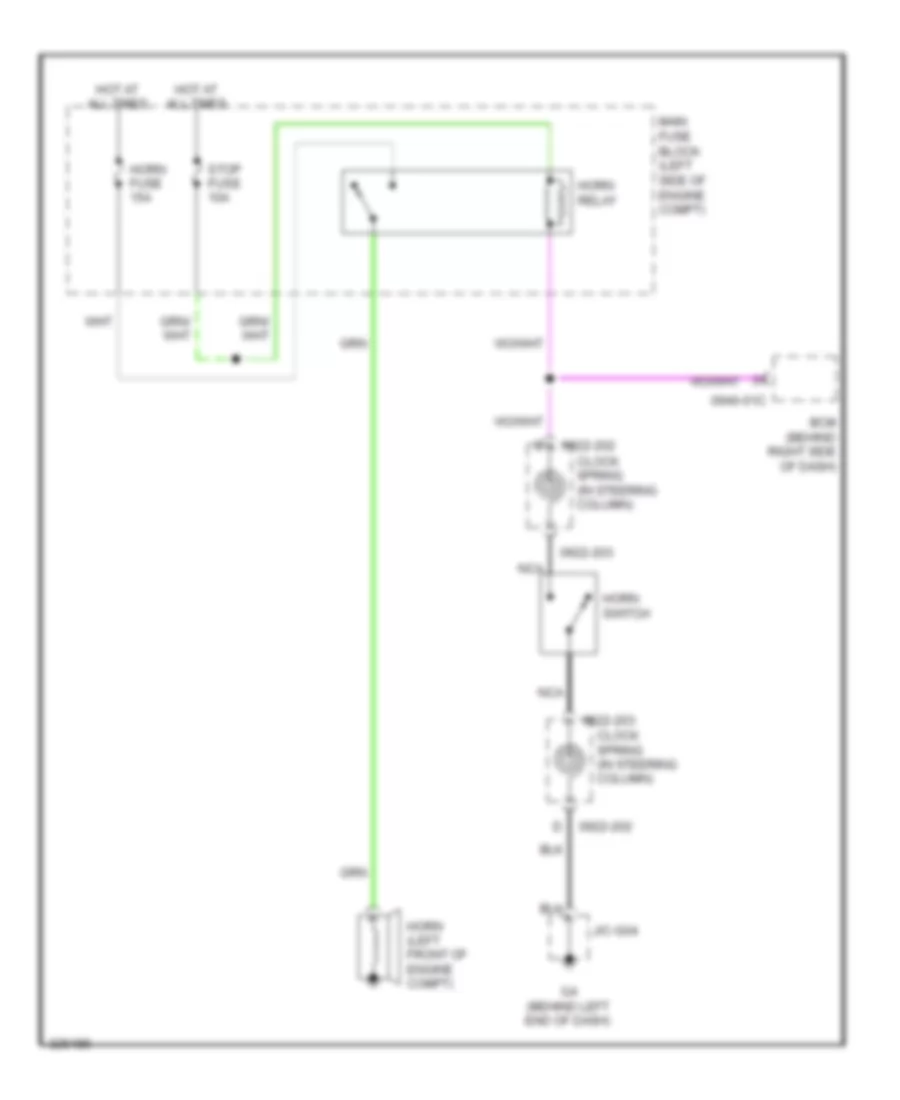
HORN
Horn Wiring Diagram for Mazda 5 Grand Touring 2010
List of elements for Horn Wiring Diagram for Mazda 5 Grand Touring 2010:
- 0922-202
- 0922-203
- 0940-01c
- Bcm (behind right side of dash)
- Clock spring (in steering column)
- G4 (behind left end of dash)
- Horn (left front of engine compt)
- Horn fuse 15a
- Horn relay
- Horn switch
- Hot at all times
- J/c-g04
- Main fuse block (left side of engine compt)
- Nca
- Stop fuse 10a
INSTRUMENT CLUSTER
Instrument Cluster Wiring Diagram for Mazda 5 Grand Touring 2010
List of elements for Instrument Cluster Wiring Diagram for Mazda 5 Grand Touring 2010:
- (behind left end of dash) g4
- (behind left headlight) g1
- (lower left side of engine) oil pressure switch
- (rear of engine) g14
- (under driver's seat) g10
- 0920-301a
- 0922-101a
- 0922-101b
- 0940-01a
- 0940-01b
- 0940-01d
- 0940-01e
- 1-5
- 4wd abs ind
- Air bag ind
- Anti-theft system
- At ind
- Bcm (behind right side of dash)
- Brake fluid level sensor (in brake fluid reservoir)
- Brake ind
- Brake switch 2 (at top of brake pedal assembly)
- Buzzer
- Car-navigation unit (w/ navigation) (behind right side of dash)
- Charge ind
- Check engine ind
- Computer data lines system
- Cruise (amber) ind
- Cruise (green) ind
- Door ind
- Door locks system
- Drive circuit selector indicator
- Eps ind
- Fuel gauge
- Fuel gauge sender unit (on fuel tank)
- Fuel low ind
- Fuse block (behind right end of dash)
- G10 (under driver's seat)
- G11 (under front passenger's seat)
- Hi beam ind
- Hot at all times
- Hot in on or start
- Illum ind
- Instrument cluster
- Interior lights system
- J/c c-11 (behind right end of dash)
- J/c c-12 (behind center of dash)
- J/c c-31 (behind left end of dash)
- J/c g-04
- L turn ind
- Left front door latch switch (in driver's door)
- Left rear slide door switch (at left rear "c" pillar)
- Main fuse block (left side of engine compt)
- Meter fuse 10a
- Microcomputer
- Navigation system
- Odometer/ tripmeter
- Oil ind
- Panel light control
- Parking brake switch (at base of parking brake lever)
- R turn ind
- Red
- Right front door latch switch (in front passenger's door)
- Right rear slide door switch (at right rear "c" pillar)
- Room fuse 15a
- Seat belts ind
- Security ind
- Speedometer
- Tachometer
- Tns ind
- Tpms control unit
- Tpms ind
- Tripmeter switch
- Warning systems
- Washer ind
- Water temperature gauge
- Wiper/washer system
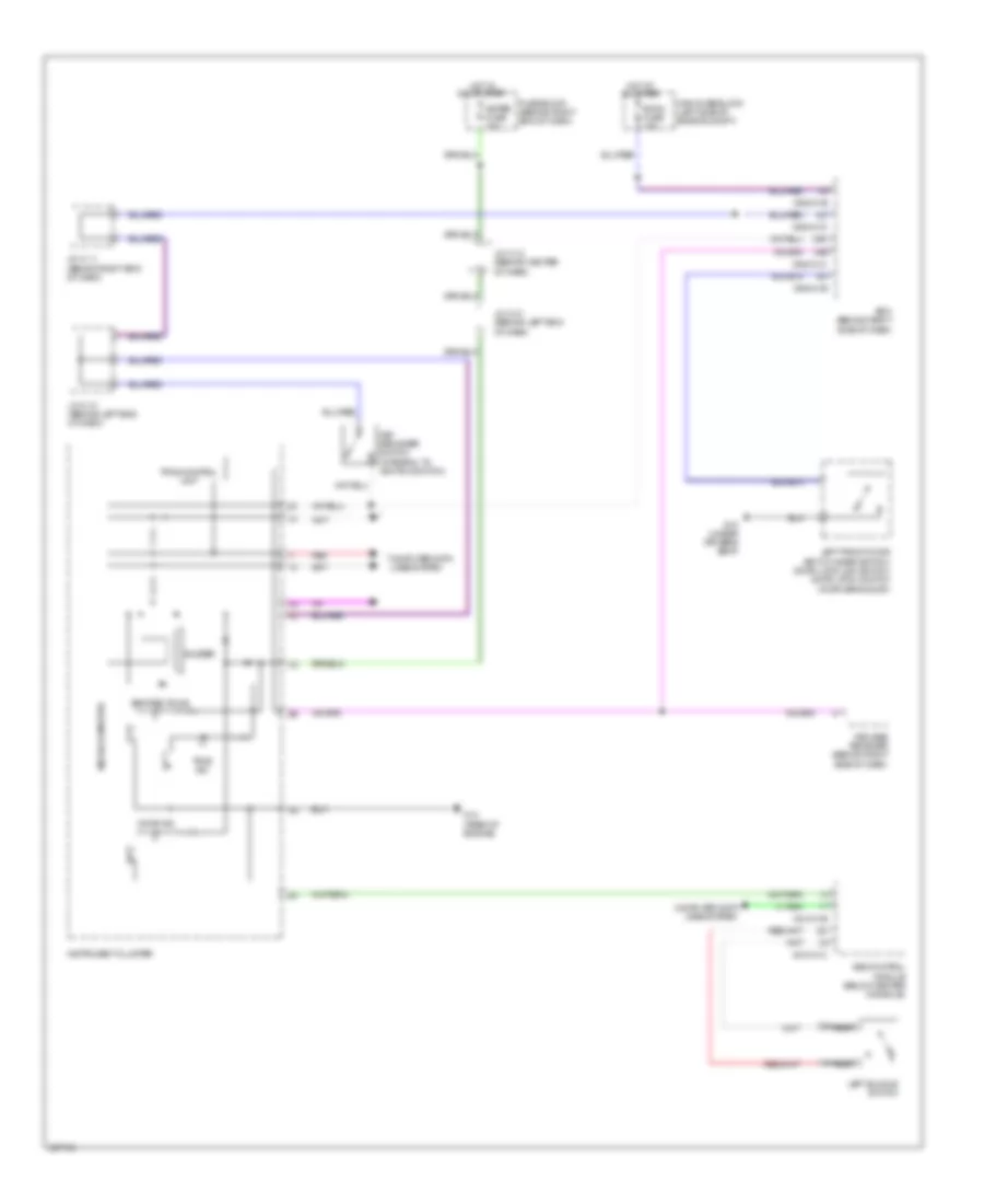
Multi-Information System Wiring Diagram for Mazda 5 Grand Touring 2010
List of elements for Multi-Information System Wiring Diagram for Mazda 5 Grand Touring 2010:
- (behind right end of dash) j/c c-11
- (behind right side of dash) bcm
- 0940-01b
- 0940-01d
- Clock switch
- Computer data lines system
- Fuse block (behind right end of dash)
- G4 (behind left end of dash)
- Hot at all times
- Hot in on or acc
- Information display
- Interior lights system
- J/c g-04
- Main fuse block (left side of engine compt)
- Mirror fuse 7.5a
- Room fuse 15a
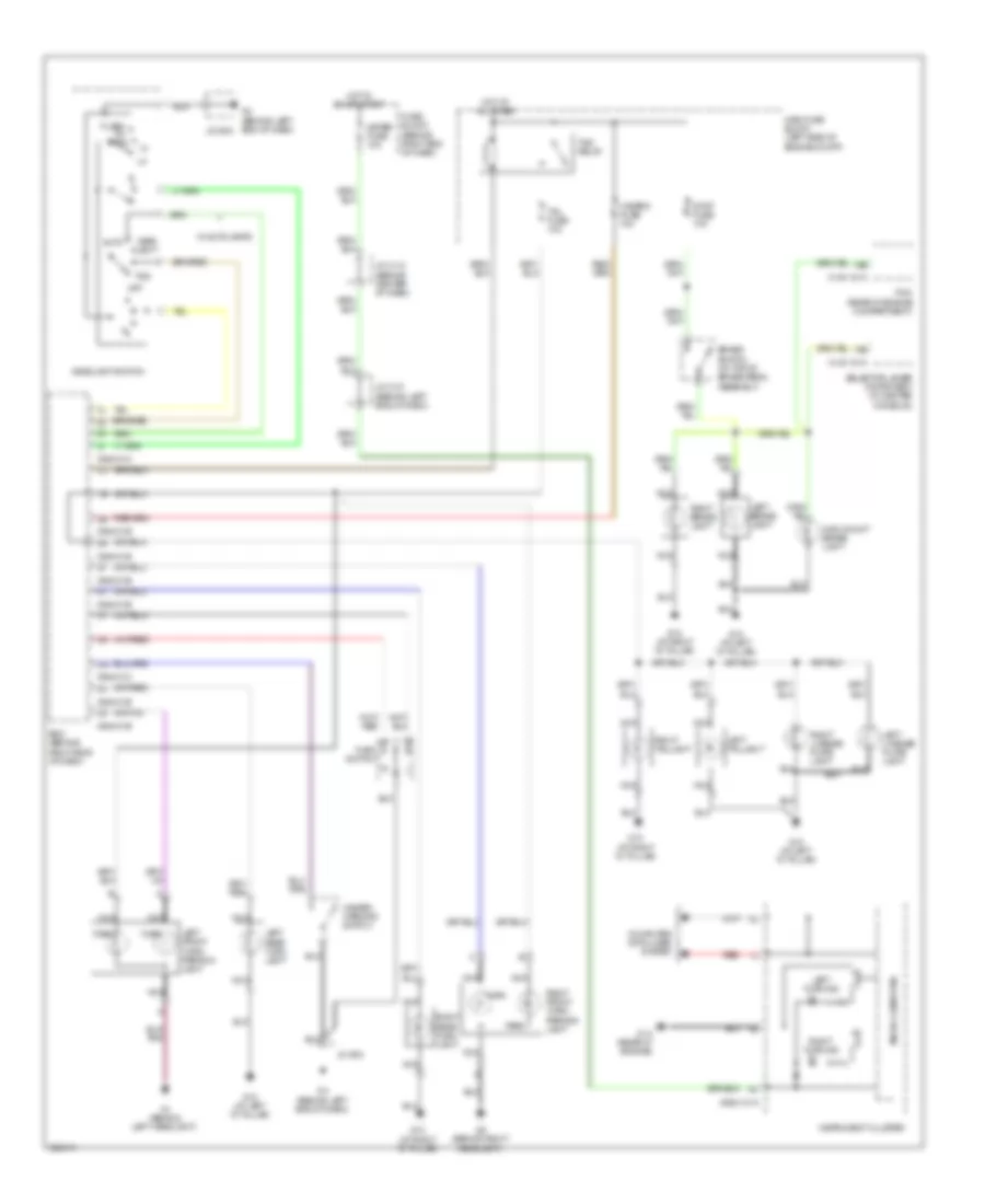
INTERIOR LIGHTS
Courtesy Lamps Wiring Diagram for Mazda 5 Grand Touring 2010
List of elements for Courtesy Lamps Wiring Diagram for Mazda 5 Grand Touring 2010:
- 0940-01b
- 0940-01e
- 0940-01f
- Body control module (behind right side of dash)
- Cargo compartment light
- Door
- G10 (under driver's seat)
- G11 (under front passenger's seat)
- G12 (at left "d" pillar)
- Hot at all times
- Interior light
- Left
- Left front door key cylinder switch/ door lock-link switch/door latch switch (in driver's door)
- Liftgate latch switch (on liftgate latch)
- Main fuse block (left side of engine compartment)
- Map light
- Nca
- Off
- Red
- Right
- Right front door latch switch (in front passenger's door)
- Room fuse 15a
Instrument Illumination Wiring Diagram for Mazda 5 Grand Touring 2010
List of elements for Instrument Illumination Wiring Diagram for Mazda 5 Grand Touring 2010:
- (5 leds & resisters)
- (w/ rear vent
- 0920-201a
- 0920-301a
- 0922-202
- 0922-203
- 0940-01a
- 0940-01b
- 0940-01c
- 0940-01d
- Audio control switch (w/o cruise control)
- Audio unit (w/o car navigation) car navigation unit (w/ car navigation) (behind right side of dash)
- Auto
- Body control module (behind right side of dash)
- Climate control unit (lower center of dash)
- Clock spring (in steering column)
- Cruise control switch illumination (w/ cruise control)
- Flash- to- pass
- G14 (rear of engine)
- G4 (behind left end of dash)
- Hazard warning switch & clock switch /dsc off switch illumination
- Head light
- Headlight switch
- Hot at all times
- Ignition key illumination
- Ill
- Illu fuse 10a
- Information display
- Instrument cluster
- Jc c-11 (behind right end of dash)
- Jc c-29 (behind left end of dash)
- Jc c-31 (behind left end of dash)
- Jc c-33 (behind left end of dash)
- Jc-g04
- Left seat warmer switch (if equipped)
- Main fuse block (left side of engine compartment)
- Microcomputer
- Nca
- Off
- Rear fan switch
- Right seat warmer switch illumination (if equipped)
- Room fuse 15a
- Selector illumination (a/t)
- Tns
- Tns ind
- Tns relay
- W/ auto lamps
- W/ car navigation
- W/o car navigation
NAVIGATION
Navigation Wiring Diagram (1 of 2) for Mazda 5 Grand Touring 2010
List of elements for Navigation Wiring Diagram (1 of 2) for Mazda 5 Grand Touring 2010:
- 0920-301a
- 0920-301b
- 0920-317
- 0922-101b
- Auxiliary jack
- Car navigation unit (behind right side of dash)
- Computer data lines system
- Fuse block (behind right end of dash)
- G8 (behind right side of dash)
- Hot in on or acc
- Hot in on or start
- Instrument cluster
- Instrument cluster system
- Interior lights system
- Joint connector c11 (behind right end of dash)
- Left front door speaker
- Left rear speaker
- Left tweeter
- Meter fuse 10a
- Mirror fuse 7.5a
- Nca
- Pnk
- Red
- Right front door speaker
- Right rear speaker
- Right tweeter
Navigation Wiring Diagram (2 of 2) for Mazda 5 Grand Touring 2010
List of elements for Navigation Wiring Diagram (2 of 2) for Mazda 5 Grand Touring 2010:
- (behind center of dash) joint connector c12
- 0922-202 g
- 0922-203
- 0940-01a
- 0940-01d
- A/t
- Audio control switch
- Backup light switch (on transaxle)
- Bcm (behind right side of dash)
- Clock spring (in steering column)
- Computer data lines system
- Exterior lights system
- G4 (behind left end of dash)
- Hands-free telephone unit (if equipped)
- Instrument cluster system
- J/c g04
- Joint connector c11 (behind right end of dash)
- M/t
- Microphone (behind right center of dash)
- Mode
- Mute
- Nca
- Preset +
- Preset -
- R position
- Red
- Transaxle range switch (on transaxle)
- Transmissions system
- Vol +
- Vol -
- W/ handsfree telephone unit
- W/o handsfree telephone unit
POWER DISTRIBUTION
Power Distribution Wiring Diagram (1 of 2) for Mazda 5 Grand Touring 2010
List of elements for Power Distribution Wiring Diagram (1 of 2) for Mazda 5 Grand Touring 2010:
- (left side of engine compt) main fuse block
- 250a
- Abs p fuse 30a
- Abs v fuse 20a
- Air conditioning system
- Anti-lock brakes system
- Battery
- Btn fuse 60a
- Cooling fans system
- D lock fuse 20a
- Door locks system
- Eng +b fuse 10a
- Eng ba fuse 20a
- Eng bar 2 fuse 15a
- Eng bar fuse 15a
- Engine controls system
- Etc fuse 10a
- Exterior lights system
- Fan fuse 30a
- From hazard a fuse (diagram 1 of 2)
- Fuel fuse 20a
- Hazard fuse 10a
- Head high l 10a
- Head high r 10a
- Head low l 15a
- Head low r 15a
- Headlight high relay
- Headlight low relay
- Headlights system
- Horn fuse 15a
- Horns system
- Illumi fuse 10a
- Interior lights system
- Left closer fuse 20a
- Mag fuse 10a
- Main fuse
- Main relay
- Nca
- Power tops system
- Right closer fuse 20a
- Starting/ charging system
- Stop fuse 10a
- Sun roof fuse 20a
- Tail fuse 10a
- Tcm fuse 20a
- Tns relay (tail relay)
- To defog fuse (diagram 2 of 2)
- To tns relay (diagram 1 of 2)
- Transmissions system
- Trunk, tailgate, fuel doors system
Power Distribution Wiring Diagram (2 of 2) for Mazda 5 Grand Touring 2010
List of elements for Power Distribution Wiring Diagram (2 of 2) for Mazda 5 Grand Touring 2010:
- (behind right end of dash) fuse block
- (left side of engine compt) main fuse block
- A/c fuse 10a
- Abs/dsc fuse 5a
- Acc
- Air conditioning & body computer systems
- Air conditioning system
- Air conditioning, door locks, instrument cluster, computer data lines, shift interlock, interior lights, navigation, sound & body computer systems
- Blower fuse (w/o rear vent) 40a
- Cigar fuse 15a
- Defog fuse 25a
- Defogger system
- Ehpas fuse 5a
- Ehpas fuse 80a
- Electronic power steering & anti-lock brakes systems
- Electronic power steering system
- Eng 2 fuse 15a
- Eng 3 fuse 20a
- Eng fuse 5a
- Engine controls & cooling fans systems
- Engine controls system
- F blower fuse (w/ rear vent) 20a
- F wip fuse 25a
- Fog fuse 15a
- From tcm b fuse (diagram 1 of 2)
- Front accessory socket
- G12 (at left "d" pillar)
- G6 (behind right end of dash)
- Headlights system
- Ig key 1 fuse 40a
- Ig key 2 fuse 40a
- Ig1
- Ig2
- Ignition switch
- Instrument cluster, wiper/washer, exterior lights, door locks, anti-theft, body computer & transmissions systems
- Joint connector g-06
- Meter fuse 10a
- Mirror fuse 7.5a
- Off
- P/outlet fuse 15a
- P/w fuse 30a
- Pnk
- Power windows system
- R blower fuse 30a
- R wip fuse 15a
- Rear accessory socket
- Room fuse 15a
- Run
- S warm fuse 15a
- Sas fuse 10a
- Seats system
- Shift interlock system
- Shift/l fuse 5a
- Sound, mirrors & navigation systems
- Start
- Starting/ charging system
- Wiper/washer system
POWER DOOR LOCKS
Power Door Locks Wiring Diagram for Mazda 5 Grand Touring 2010
List of elements for Power Door Locks Wiring Diagram for Mazda 5 Grand Touring 2010:
- (at left "d" pillar)
- (at left rear "c" pillar) left rear slide door switch
- (at right rear "c" pillar) right rear slide door switch
- 0922-101b
- 0940-01a
- 0940-01c
- 0940-01e
- 0940-01f
- 2j 0940-01b
- 3ab
- Bcm (behind right side of dash)
- Computer data lines system
- D lock fuse 20a
- Door key cylinder switch/ door lock-link switch/ left front door latch switch/ left front door lock actuator (in driver's door)
- Door lock relay
- Door unlock relay
- Double lock relay
- Fuse block (behind right end of dash)
- G10 (under driver's seat)
- G11 (under front passenger's seat)
- G12
- G12 (at left "d" pillar)
- G13 (at right "d" pillar)
- G2 (behind right headlight)
- G4 (behind left end of dash)
- Hood latch switch (on hood latch assembly)
- Horns system
- Hot at all times
- Hot in on or start
- Instrument cluster
- J/c c-12 (behind center of dash)
- J/c-g04
- Keyless receiver (behind right side of dash)
- Left door lock switch
- Left rear door lock-link switch
- Left sliding door lock actuator (in left sliding door)
- Liftgate latch switch (on liftgate latch)
- Liftgate lock actuator (in liftgate)
- Lock
- Main fuse block (left side of engine compt)
- Meter fuse 10a
- Nca
- Reset
- Right door lock switch
- Right front door latch switch/ right front door lock actuator (in front passenger's door)
- Right rear door lock-link switch
- Right sliding door lock actuator (in right sliding door)
- Set
- Un- lock
- Unlock
POWER MIRRORS
Power Mirrors Wiring Diagram for Mazda 5 Grand Touring 2010
List of elements for Power Mirrors Wiring Diagram for Mazda 5 Grand Touring 2010:
- 0912-301a
- 0912-401
- Defogger system
- Down
- Fuse block (behind right end of dash)
- G10 (under driver's seat)
- Heating element
- Hot in acc or run
- J/c c-11 (behind right end of dash)
- Left
- Left power outer mirror (on left front door)
- Mirror fuse 7.5a
- Nca
- Power outer mirror switch
- Right
- Right power outer mirror (on right front door)
POWER SEATS
Power Seats Wiring Diagram for Mazda 5 Grand Touring 2010
List of elements for Power Seats Wiring Diagram for Mazda 5 Grand Touring 2010:
- Fuse block (behind right end of dash)
- G10 (under driver's seat)
- G11 (under front passenger's seat)
- Hot in run
- Interior lights system
- Left seat warmer switch
- Left seat warmer unit
- Nca
- Right seat warmer switch
- Right seat warmer unit
- S warm fuse 15a
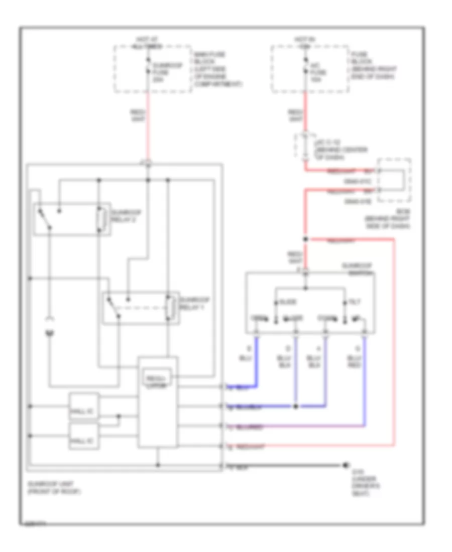
POWER TOP/SUNROOF
Power Top/Sunroof Wiring Diagram for Mazda 5 Grand Touring 2010
List of elements for Power Top/Sunroof Wiring Diagram for Mazda 5 Grand Touring 2010:
- 0940-01c
- 0940-01e
- A/c fuse 10a
- Bcm (behind right side of dash)
- Close
- Down
- Fuse block (behind right end of dash)
- G10 (under driver's seat)
- Hall ic
- Hot at all times
- Hot in on
- J/c c-12 (behind center of dash)
- Main fuse block (left side of engine compartment)
- Open
- Regu- lator
- Slide
- Sunroof fuse 20a
- Sunroof relay 1
- Sunroof relay 2
- Sunroof switch
- Sunroof unit (front of roof)
- Tilt
POWER WINDOWS
Power Windows Wiring Diagram for Mazda 5 Grand Touring 2010
List of elements for Power Windows Wiring Diagram for Mazda 5 Grand Touring 2010:
- Auto
- Close
- Fuse block (behind right end of dash)
- G10 (under driver's seat)
- Hot in run or start
- Left front power window motor (in left front door)
- Left rear power window motor (in left rear door)
- Left rear power window sub switch
- Open
- Open relay
- P/w cm
- P/w fuse 30a
- Power window main switch
- Power-cut switch
- Red
- Right front power window motor (in right front door)
- Right front power window sub switch
- Right rear power window motor (in right rear door)
- Right rear power window sub switch
RADIO
Radio Wiring Diagram, with Navigation (1 of 2) for Mazda 5 Grand Touring 2010
List of elements for Radio Wiring Diagram, with Navigation (1 of 2) for Mazda 5 Grand Touring 2010:
- 0920-301a
- 0920-301b
- 0920-317
- 0922-101b
- Auxiliary jack
- Car navigation unit (behind right side of dash)
- Computer data lines system
- Fuse block (behind right end of dash)
- G8 (behind right side of dash)
- Hot in on or acc
- Hot in on or start
- Instrument cluster
- Instrument cluster system
- Interior lights system
- Joint connector c11 (behind right end of dash)
- Left front door speaker
- Left rear speaker
- Left tweeter
- Meter fuse 10a
- Mirror fuse 7.5a
- Nca
- Pnk
- Red
- Right front door speaker
- Right rear speaker
- Right tweeter
Radio Wiring Diagram, with Navigation (2 of 2) for Mazda 5 Grand Touring 2010
List of elements for Radio Wiring Diagram, with Navigation (2 of 2) for Mazda 5 Grand Touring 2010:
- (behind center of dash) joint connector c12
- 0922-202 g
- 0922-203
- 0940-01a
- 0940-01d
- A/t
- Audio control switch
- Backup light switch (on transaxle)
- Bcm (behind right side of dash)
- Clock spring (in steering column)
- Computer data lines system
- Exterior lights system
- G4 (behind left end of dash)
- Hands-free telephone unit (if equipped)
- Instrument cluster system
- J/c g04
- Joint connector c11 (behind right end of dash)
- M/t
- Microphone (behind right center of dash)
- Mode
- Mute
- Nca
- Preset +
- Preset -
- R position
- Red
- Transaxle range switch (on transaxle)
- Transmissions system
- Vol +
- Vol -
- W/ handsfree telephone unit
- W/o handsfree telephone unit
Radio Wiring Diagram, without Navigation for Mazda 5 Grand Touring 2010
List of elements for Radio Wiring Diagram, without Navigation for Mazda 5 Grand Touring 2010:
- 0920-201a
- 0920-210b
- 0922-203
- 0940-01d
- Audio control switch
- Audio unit
- Auxiliary jack
- Bcm (behind right end of dash)
- Clock spring (in steering column)
- Computer data lines system
- E 0922-202
- Fuse block (behind right end of dash)
- G4 (behind left end of dash)
- G8 (behind right side of dash)
- Hands-free telephone unit (if equipped)
- Hot in on or acc
- Interior lights system
- J/c-g04
- Joint connector 11 (behind right end of dash)
- Joint connector c11 (behind right end of dash)
- Left front door speaker
- Left rear speaker
- Left tweeter
- Microphone (behind right center of dash) (w/ hands-free telephone unit)
- Mirror fuse 7.5a
- Mode
- Mute
- Nca
- Pnk
- Preset +
- Preset -
- Red
- Right front door speaker
- Right rear speaker
- Right tweeter
- Vol +
- Vol -
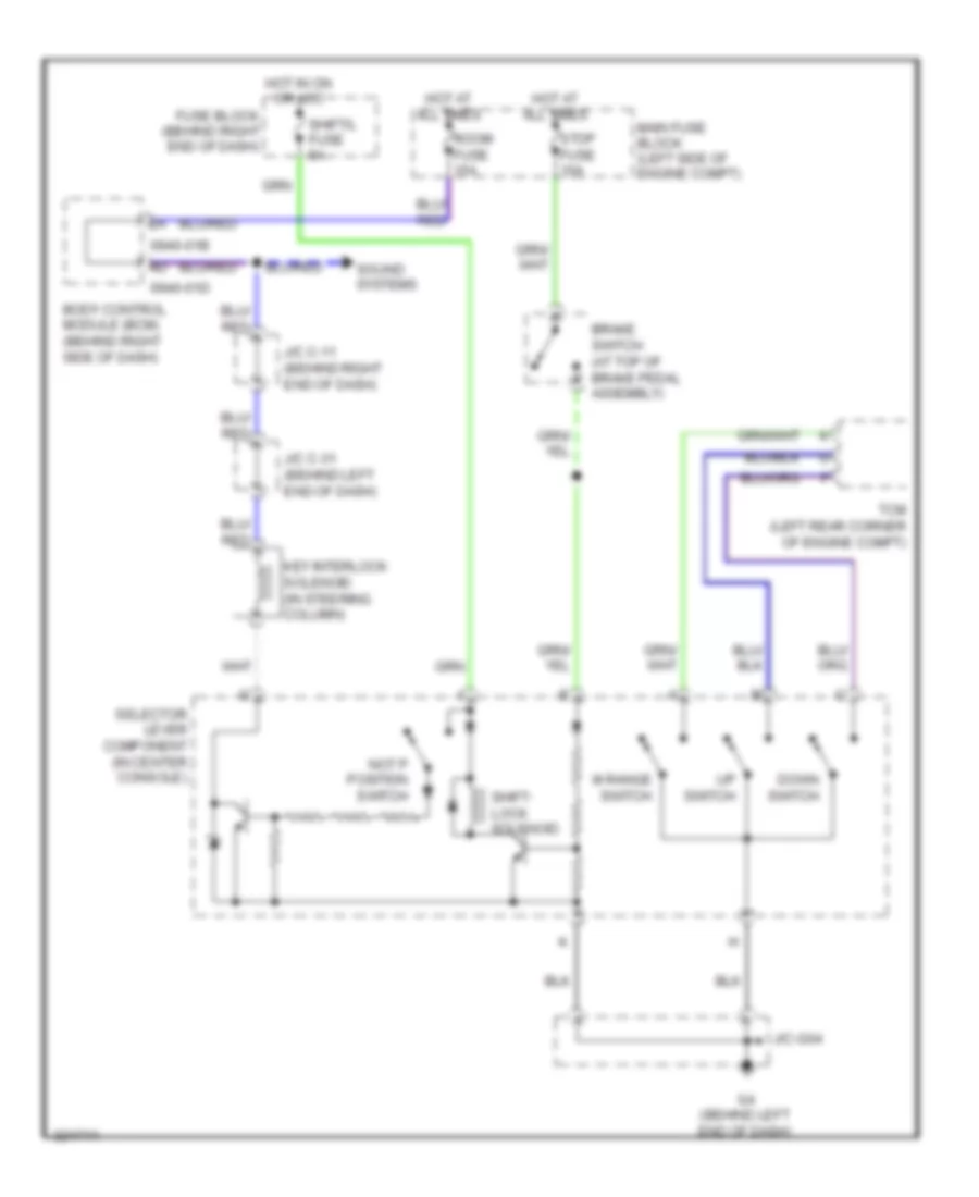
SHIFT INTERLOCK
Shift Interlock Wiring Diagram for Mazda 5 Grand Touring 2010
List of elements for Shift Interlock Wiring Diagram for Mazda 5 Grand Touring 2010:
- 0940-01b
- 0940-01d
- Body control module (bcm) (behind right side of dash)
- Brake switch (at top of brake pedal assembly)
- Down switch
- Fuse block (behind right end of dash)
- G4 (behind left end of dash)
- Hot at all times
- Hot in on or acc
- J/c c-11 (behind right end of dash)
- J/c c-31 (behind left end of dash)
- J/c-g04
- Key interlock solenoid (in steering column)
- M range switch
- Main fuse block (left side of engine compt)
- Not p position switch
- Room fuse 15a
- Selector lever component (in center console)
- Shift- lock solenoid
- Shift/l fuse 5a
- Sound systems
- Stop fuse 10a
- Tcm (left rear corner of engine compt)
- Up switch
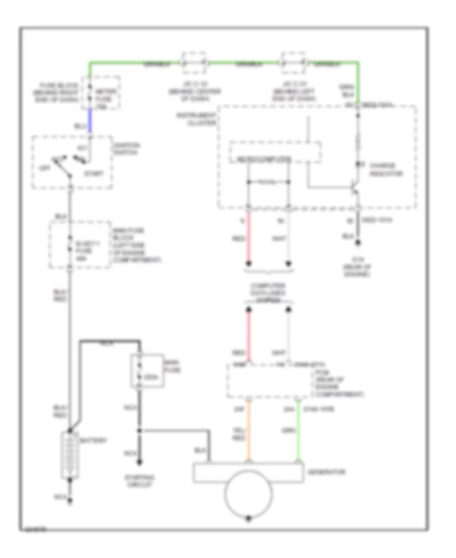
STARTING/CHARGING
Charging Wiring Diagram for Mazda 5 Grand Touring 2010
List of elements for Charging Wiring Diagram for Mazda 5 Grand Touring 2010:
- 0140-101a
- 0140-101b
- 0922-101a
- 1ai
- 1am
- 250a
- 2aa
- 2af
- Acc
- Battery
- Charge
- Computer data lines system
- Fuse block (behind right end of dash)
- G14 (rear of engine)
- Generator
- Ig key 1 fuse 40a
- Ig1
- Ignition switch
- Indicator
- Instrument cluster
- J/c c-12 (behind center of dash)
- J/c c-31 (behind left end of dash)
- Main fuse
- Main fuse block (left side of engine compartment)
- Meter fuse 10a
- Microcomputer
- Nca
- Off
- Pcm (rear of engine compartment)
- Red
- Start
- Starting circuit
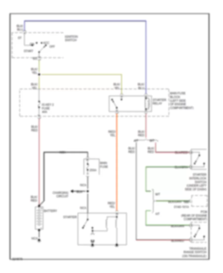
Starting Wiring Diagram for Mazda 5 Grand Touring 2010
List of elements for Starting Wiring Diagram for Mazda 5 Grand Touring 2010:
- 0140-101a
- 1bb
- 250a
- A/t
- Acc
- Battery
- Charging circuit
- Ig key 2 fuse 40a
- Ignition switch
- M/t
- Main fuse
- Main fuse block (left side of engine compartment)
- Nca
- Off
- Pcm (rear of engine compartment)
- Start
- Starter
- Starter interlock switch (under left side of dash)
- Starter relay
- Transaxle range switch (on transaxle)
SUPPLEMENTAL RESTRAINTS
Supplemental Restraints Wiring Diagram (1 of 2) for Mazda 5 Grand Touring 2010
List of elements for Supplemental Restraints Wiring Diagram (1 of 2) for Mazda 5 Grand Touring 2010:
- (at front of engine compt) crash zone sensor
- (behind left side of dash) g7
- 0810-01a
- 0810-01b
- 0810-01c
- 0810-20a
- 0810-20b
- 0810-20c
- 2aa
- Bcm (behind right side of dash)
- Computer data lines system
- Driver side pretensioner seat belt (base of left "b" pillar)
- Fuse block (behind right end of dash)
- G11 (under front passenger's seat)
- Hot in run or start
- Inflator
- J/c c-12 (behind center of dash)
- J/c c-31 (behind left end of dash)
- Left buckle switch
- Left seat weight sensor (in front
- Meter fuse 10a
- Nca
- Passenger air bag deactivation (pad) indicator
- Passenger side pretensioner seat belt (base of right "b" pillar)
- Passenger's seat cushion)
- Pnk
- Red
- Right buckle switch
- Right seat weight sensor (in front passenger's seat cushion)
- Sas control module (below center console)
- Sas fuse 10a
- Seat track position sensor (under driver's seat)
- Seat weight sensor control module (under front passenger's seat)
- Short bar
Supplemental Restraints Wiring Diagram (2 of 2) for Mazda 5 Grand Touring 2010
List of elements for Supplemental Restraints Wiring Diagram (2 of 2) for Mazda 5 Grand Touring 2010:
- (rear of engine) g14
- 0922-101a
- 0922-101b
- Air bag ind
- Clock spring (in steering column)
- Driver side air bag module (center of steering wheel)
- Driver side curtain air bag module (in left "d" pillar)
- Driver side side air bag module
- Driver side side air bag sensor 1 (at base of left "b" pillar)
- Driver side side air bag sensor 2 (at base of left "c" pillar)
- Inflator
- Inflator 1
- Inflator 2
- Instrument cluster
- Microcomputer
- Nca
- Passenger side air bag module (behind right side of dash)
- Passenger side curtain air bag module (in right "d" pillar)
- Passenger side side air bag module
- Passenger side side air bag sensor 1 (at base of right "b" pillar)
- Passenger side side air bag sensor 2 (at base of right "c" pillar)
- Red
- Seat belts ind
- Short bar
TRANSMISSION
Transmission Wiring Diagram (1 of 2) for Mazda 5 Grand Touring 2010
List of elements for Transmission Wiring Diagram (1 of 2) for Mazda 5 Grand Touring 2010:
- (in transaxle) g15
- 0517-04
- 0517-06
- 0922-101a
- 0940-01a
- 0940-01d
- 1-5
- A/t ind
- Bcm (behind right side of dash)
- Computer data lines system
- Fuse block (behind right end of dash)
- G14 (rear of engine)
- G17 (left front of engine compt)
- Hot in on or start
- Input/turbine speed sensor (on transaxle)
- Instrument cluster
- J/c c-12 (behind center of dash)
- J/c c-31 (behind left end of dash)
- Meter fuse 10a
- Micro- computer
- Oil pressure switch (on left side of transaxle)
- Pressure control solenoid b
- Primary solenoid valve
- Red
- Secondary solenoid valve
- Selector indicator drive circuit
- Solenoid a control pressure
- Solenoid a shift
- Solenoid b shift
- Solenoid c shift
- Solenoid d shift
- Solenoid e shift
- Solenoid f shift
- Tcm (left rear corner of engine compt)
- Temperature fluid sensor
- Transaxle case
Transmission Wiring Diagram (2 of 2) for Mazda 5 Grand Touring 2010
List of elements for Transmission Wiring Diagram (2 of 2) for Mazda 5 Grand Touring 2010:
- (on transaxle) transaxle range switch
- At main relay
- Down sw
- Eng b+ fuse 10a
- Exterior lights system
- G14 (rear of engine)
- Hot at all times
- Interior lights system
- Intermediate sensor
- J/c g-04 (behind left end of dash)
- M range sw
- Main fuse block (left side of engine compt)
- Not p position sw
- Selector lever component (in center console)
- Shift interlock system
- Shift lock solenoid
- Starting/ charging system
- Tcm fuse 20a
- Up sw
- Vehicle speed sensor (on transaxle)
TRUNK, TAILGATE, FUEL DOOR
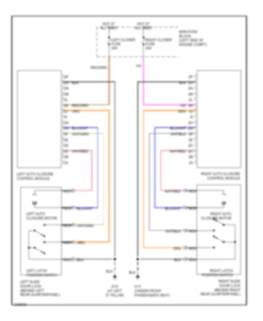
Power Sliding Door Wiring Diagram for Mazda 5 Grand Touring 2010
List of elements for Power Sliding Door Wiring Diagram for Mazda 5 Grand Touring 2010:
- G11 (under front passenger's seat)
- G12 (at left "d" pillar)
- Hot at all times
- Left auto closure control module
- Left auto closure motor
- Left closer fuse 20a
- Left latch position switch
- Left slide door lock (behind left rear quarterpanel)
- Main fuse block (left side of engine compt)
- Nca
- Right auto closure control module
- Right auto closure motor
- Right closer fuse 20a
- Right latch position switch
- Right slide door lock (behind right rear quarterpanel)
WARNING SYSTEMS
Warning Systems Wiring Diagram for Mazda 5 Grand Touring 2010
List of elements for Warning Systems Wiring Diagram for Mazda 5 Grand Touring 2010:
- 0810-01b
- 0810-01c
- 0940-01b
- 0940-01c
- 0940-01d
- 0940-01e
- 3ab
- 3ad
- Bcm (behind right side of dash)
- Buzzer
- Computer data lines system
- Door ind
- Fuse block (behind right end of dash)
- G10 (under driver's seat)
- G14 (rear of engine)
- Hot at all times
- Hot in on or start
- Instrument cluster
- J/c c-11 (behind right end of dash)
- J/c c-12 (behind center of dash)
- J/c c-31 (behind left end of dash)
- Key reminder switch (integral to ignition switch)
- Keyless receiver (behind right side of dash)
- Left buckle switch
- Left front door key cylinder switch/ door lock-link switch/ door latch switch (in driver's door)
- Main fuse block (left side of engine compt)
- Meter fuse 10a
- Microcomputer
- Nca
- Red
- Room fuse 15a
- Sas control module (below center console)
- Seat belts ind
- Tpms control unit
- Tpms ind
WIPER/WASHER
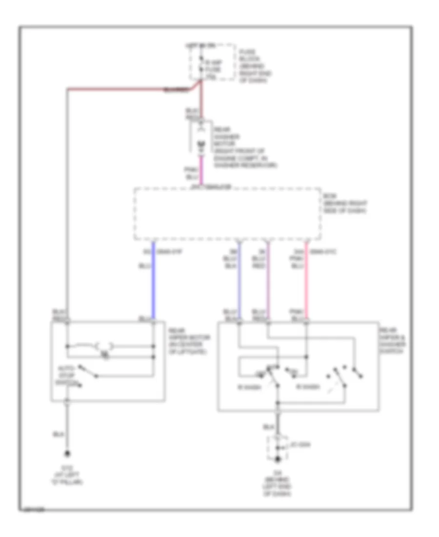
Front Wiper/Washer Wiring Diagram for Mazda 5 Grand Touring 2010
List of elements for Front Wiper/Washer Wiring Diagram for Mazda 5 Grand Touring 2010:
- (behind right side of dash) bcm
- (w/o auto wiper) int (w/ auto wiper) auto
- 0940-01c
- 0940-01d
- 1g 0922-101a
- 1m 0922-101a
- 2i 0940-01b
- 3a 0940-01c
- 5t 0940-01e
- Autostop switch
- Circuit breaker
- Computer data lines system
- F wip fuse 25a
- Fuse block (behind right end of dash)
- G1 (behind left headlight)
- G3 (left front of engine compt)
- G4 (behind left end of dash)
- G6 (behind right end of dash)
- Hot in on
- Hot in on or start
- Instrument cluster
- J/c c-12 (behind center of dash)
- J/c c-31 (behind left end of dash)
- J/c-g04
- J/c-g06
- Meter fuse 10a
- Micro- computer
- Mist
- Nca
- Off
- Rain sensor (w/ auto wiper) (top center of windshield)
- W/ auto wiper
- W/o auto wiper
- Washer fluid level sensor (right front corner of engine compt, in washer fluid reservoir)
- Washer ind
- Washer switch
- Windshield washer motor (right front corner of engine compt, in washer fluid reservoir)
- Windshield wiper & washer switch
- Windshield wiper high relay
- Windshield wiper motor (center rear of engine compt)
- Windshield wiper relay
Rear Wiper/Washer Wiring Diagram for Mazda 5 Grand Touring 2010
List of elements for Rear Wiper/Washer Wiring Diagram for Mazda 5 Grand Touring 2010:
- 2h 0940-01b
- 3aa 0940-01c
- 6g 0940-01f
- Auto- stop switch
- Bcm (behind right side of dash)
- Fuse block (behind right end of dash)
- G12 (at left "d" pillar)
- G4 (behind left end of dash)
- Hot in on
- Int
- Jc-g04
- Off
- R wash
- R wip fuse 15a
- Rear washer motor (right front of engine compt, in washer reservoir)
- Rear wiper & washer switch
- Rear wiper motor (in center of liftgate)