Diagram sections — 10 (16 total)
COOLING FAN DEFOGGERS HORN POWER ANTENNA POWER DOOR LOCKS POWER MIRRORS POWER WINDOWS RADIO STARTING/CHARGING WIPER/WASHER
COOLING FAN Cooling Fan Wiring Diagram, A/T for Mazda 626 GT 1991 List of elements for Cooling Fan Wiring Diagram, A/T for Mazda 626 GT 1991: 20 A/c system Check connector (left front side of engine compartment) Cooling fan fuse 30a Cooling fan motor (left front side of engine compartment) Cooling fan relay n0. 1 (left rear of engine compartment) Cooling fan relay n0. 2 (left front of engine compartment) Diode (center front of engine compartment) Ecu (behind center of i/p) G100 Hot at all times Hot in run or start Joint box (left side of i/p) Joint connector (front of left front fender) Main fuse block (left front of engine compartment) Meter fuse 4 10a Nca Resistor (left front of engine compartment) W/ a/c W/o a/c Water thermoswitch (on top front of engine) Cooling Fan Wiring Diagram, M/T for Mazda 626 GT 1991 List of elements for Cooling Fan Wiring Diagram, M/T for Mazda 626 GT 1991: 20 (left front of engine compartment) (m/t) (turbo) A/c system: a/c relay All except 1990 turbo Check connector (left front of engine compartment) Cooling fan fuse 30a Cooling fan motor (left front of engine compartment) Cooling fan relay (left front of engine compartment) Ecu (under right side of i/p) G104 Hot at all times Hot in run or start Joint box (left side of i/p) Joint connector (rear of left front fender) Main fuse block (left front of engine compartment) Meter fuse 4 10a Resistor Turbo Water thermoswitch (on top front of engine)
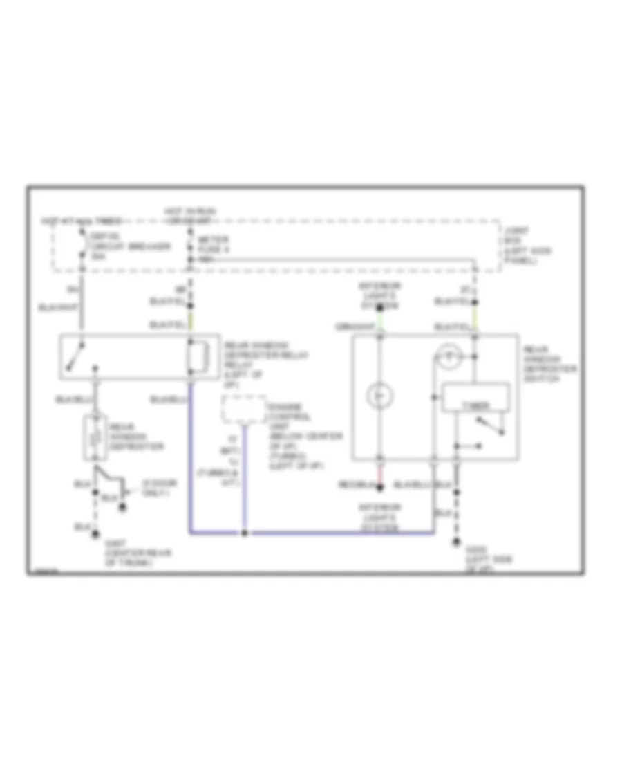
DEFOGGERS Defogger Wiring Diagram for Mazda 626 GT 1991 List of elements for Defogger Wiring Diagram for Mazda 626 GT 1991: 16 (5 door only) (m/t) 1j (turbo & a/t) Defog circuit breaker 30a Engine control unit (below center of i/p) (turbo) (left of i/p) G202 (left side of i/p) G407 (center rear of trunk) Hot at all times Hot in run or start Interior lights system Joint box (left kick panel) Meter fuse 4 10a Rear window defroster Rear window defroster relay relay (left of i/p) Rear window defroster switch Timer
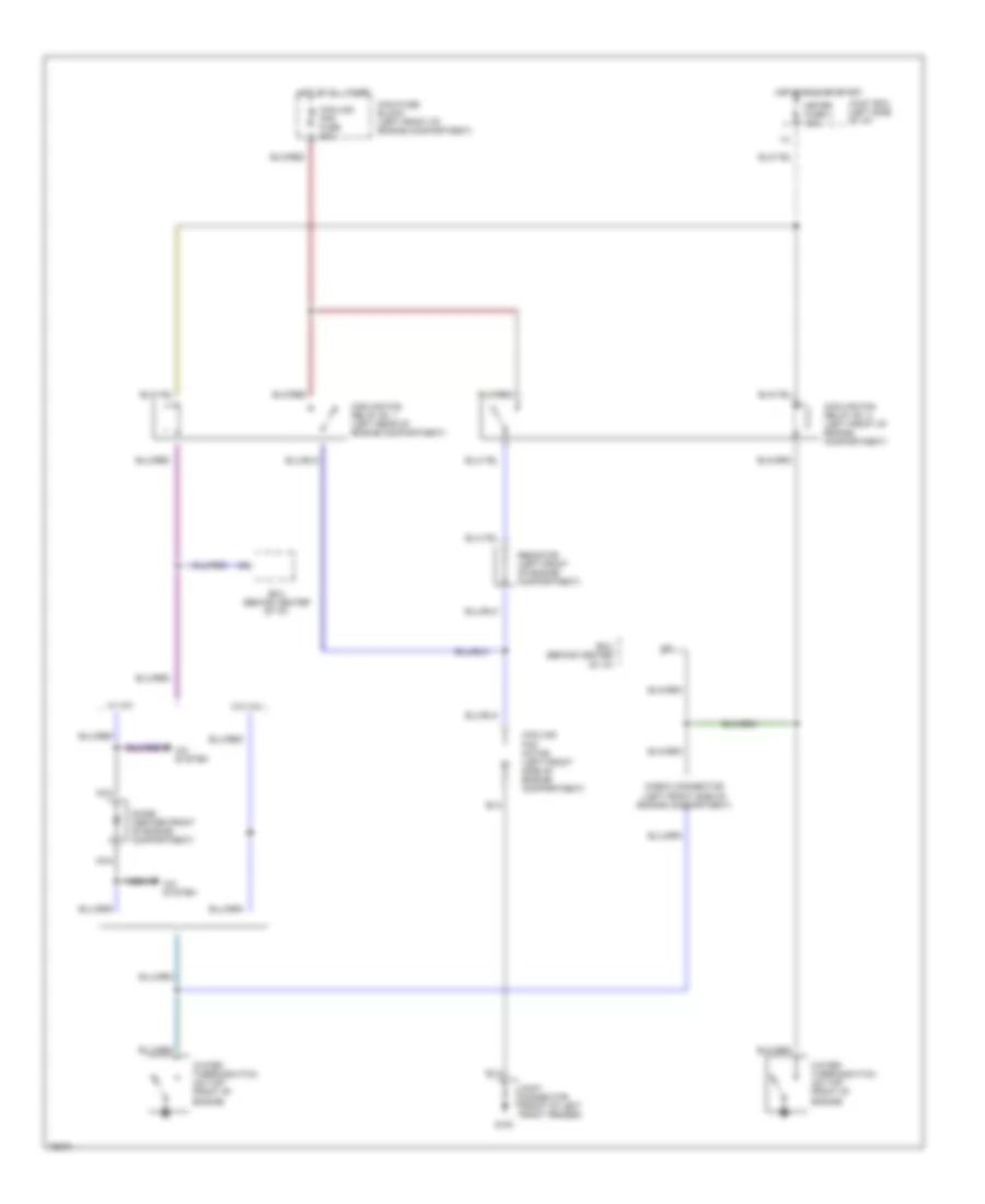
HORN Horn Wiring Diagram for Mazda 626 GT 1991 List of elements for Horn Wiring Diagram for Mazda 626 GT 1991: 8 Anti-theft system (central processing unit (cpu)) Horn relay (left rear of engine compartment) Horn switch Hot at all times Joint box (left kick panel) Left horn Right horn Stop fuse 14 15a
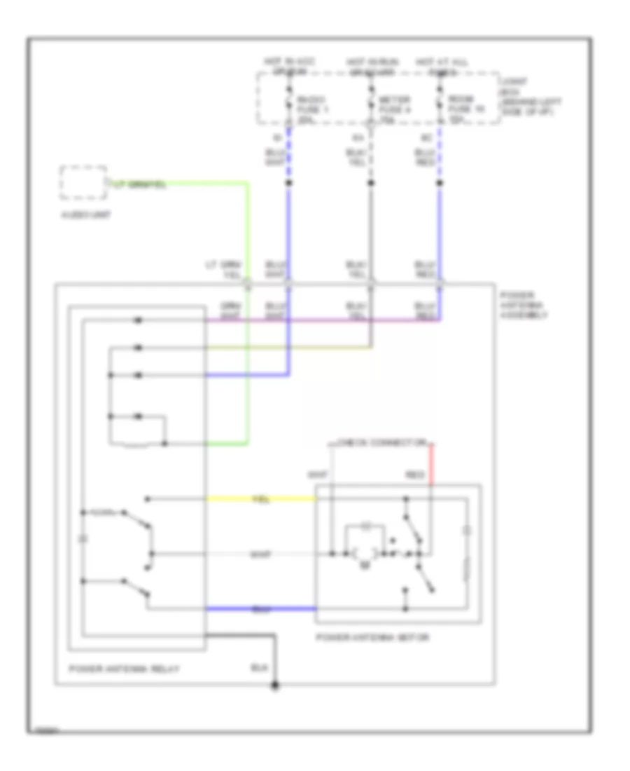
POWER ANTENNA Power Antenna Wiring Diagram for Mazda 626 GT 1991 List of elements for Power Antenna Wiring Diagram for Mazda 626 GT 1991: 13 Audio unit Check connector Hot at all times Hot in acc or run Hot in run or start Joint box (behind left side of i/p) Meter fuse 4 15a Power antenna assembly Power antenna motor Power antenna relay Radio fuse 1 15a Red Room fuse 16 15a
POWER DOOR LOCKS Back Door Lock Wiring Diagram for Mazda 626 GT 1991 List of elements for Back Door Lock Wiring Diagram for Mazda 626 GT 1991: 9 1996 vftc c G301 Hot at all times Joint box (behind left side of i/p) Joint connector (below right front seat) Rear hatch lock motor Rear hatch lock switch Rear hatch main switch Room fuse 16 15a Door Lock Wiring Diagram for Mazda 626 GT 1991 List of elements for Door Lock Wiring Diagram for Mazda 626 GT 1991: 14 1996 vftc c Central processing unit (in joint box, behind left side of i/p) Door lock fuse 13 30a G301 Hot at all times Joint box (behind left side of i/p) Joint connector (below right front seat) Left rear door lock motor Power door lock relay (left kick panel) Power door lock switch Red Right front door lock motor Right rear door lock motor Solid state
POWER MIRRORS Power Mirror Wiring Diagram for Mazda 626 GT 1991 List of elements for Power Mirror Wiring Diagram for Mazda 626 GT 1991: 12 C 1996 vftc G202 (left side of i/p) Hot in acc or run Joint box (behind left side of i/p) Left Left remote control mirror motor Left/right Radio fuse 1 15a Remote control mirror switch (switch positions) up: b1, c1 down: a1, d1 left: a1, b1 right: c1, d1 Right Right remote control mirror motor Up/down
POWER WINDOWS Power Window Wiring Diagram for Mazda 626 GT 1991 List of elements for Power Window Wiring Diagram for Mazda 626 GT 1991: 17 Close G301 Hot in run or start Joint box (behind left side of i/p) Joint connector (below right front seat) Left front power window motor Left rear power window motor Left rear power window switch Main switch Open Power window fuse 8 30a Power window main switch Red Right front power window motor Right front power window switch Right rear power window motor Right rear power window switch
RADIO Radio Wiring Diagrams for Mazda 626 GT 1991 List of elements for Radio Wiring Diagrams for Mazda 626 GT 1991: 18 (1990) (1991) Audio system Hot at all times Hot in accy or on I-28 I-29 Interior lights system: light switch J-01 J-02 Joint box (left side of i/p) Left front speaker Left rear speaker Power antenna system Radio fuse 1 15a Right front speaker Right rear speaker Room fuse 16 15a Radio Wiring Diagrams, with Full Logic Cassette Player for Mazda 626 GT 1991 List of elements for Radio Wiring Diagrams, with Full Logic Cassette Player for Mazda 626 GT 1991: 23 (1990) (1991) 3 dimension sub woofer (below center console) Acoustic equilibration system Audio system G302 Graphic equalizer Hot at all times Hot in accy or on Interior lights system: light switch Joint box (left side of i/p) Joint connector (below center console) Left front speaker Left rear speaker Nca Power antenna system Radio fuse 15a Rear amplifier (center of i/p) Right front speaker Right rear speaker Room fuse 16 15a W/ cd W/o cd
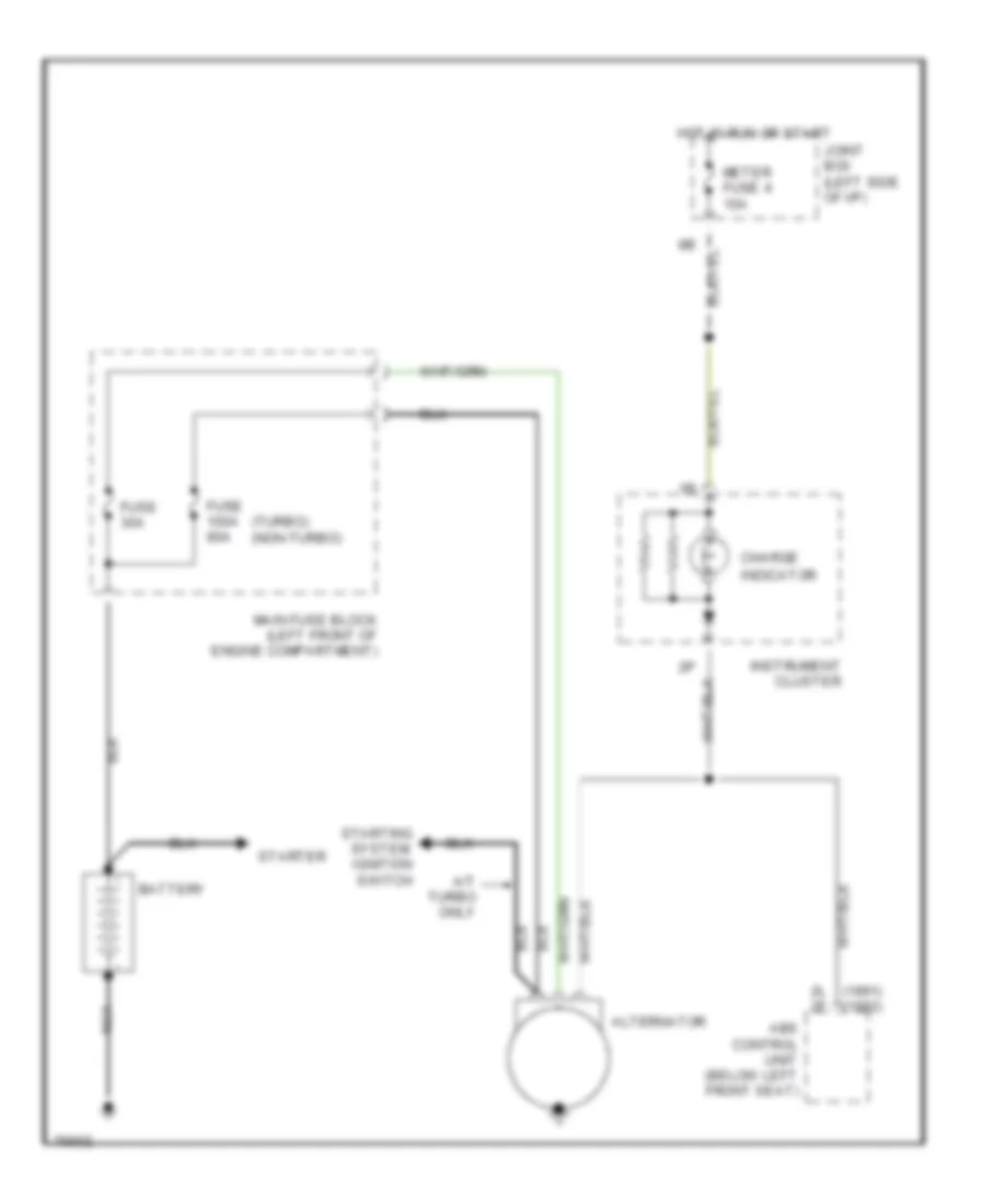
STARTING/CHARGING Charging Wiring Diagram for Mazda 626 GT 1991 List of elements for Charging Wiring Diagram for Mazda 626 GT 1991: 19 (1991) 2l 2f (1992) (turbo) (non-turbo) A/t turbo only Abs control unit (below left front seat) Alternator Battery Charge Fuse 100a 80a Fuse 30a Hot in run or start Indicator Instrument cluster Joint box (left side of i/p) Main fuse block (left front of engine compartment) Meter fuse 4 10a Nca Starter Starting system: ignition switch Starting Wiring Diagram for Mazda 626 GT 1991 List of elements for Starting Wiring Diagram for Mazda 626 GT 1991: 26 (turbo) (non-turbo) A/t Acc Alternator Battery Central processing unit (joint box) Cruise control, engine controls systems Engine controls, a/c systems Hot in run or start Ignition switch Inhibitor switch (left side of engine compartment) Joint box (left side of i/p) M/t Main fuse 100a 80a Main fuse block (left front of engine compartment) Meter fuse 4 10a Nca Non-turbo Off Start Starter Starter cut relay (left side of i/p) Starting inter lock switch (below left side of i/p) Turbo W/ anti- theft W/o anti- theft
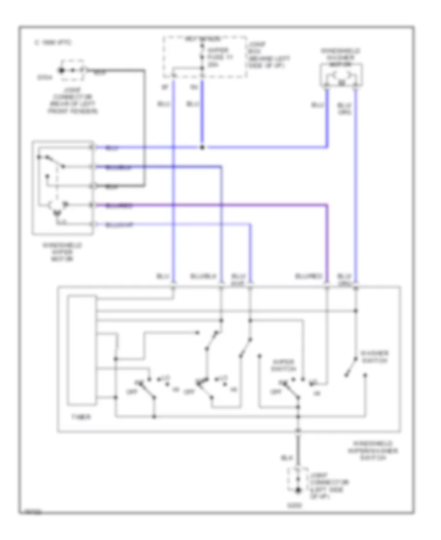
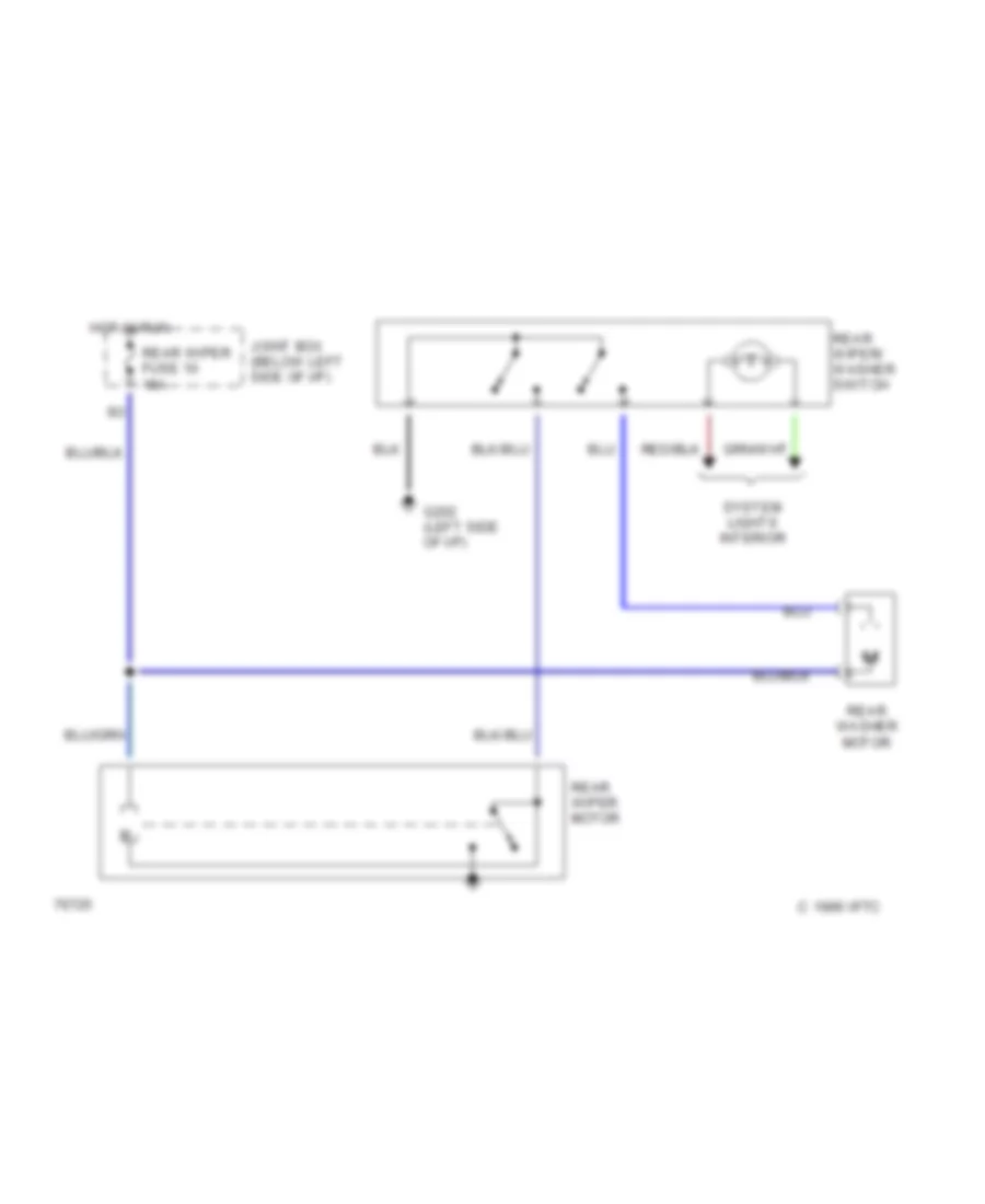
WIPER/WASHER Front Washer/Wiper Wiring Diagram for Mazda 626 GT 1991 List of elements for Front Washer/Wiper Wiring Diagram for Mazda 626 GT 1991: 16 C 1996 vftc G104 G202 Hot in run Int Joint box (behind left side of i/p) Joint connector (left side of i/p) Joint connector (rear of left front fender) Off Timer Washer switch Windshield washer motor Windshield wiper motor Windshield wiper/washer switch Wiper fuse 11 20a Wiper switch Headlamp Washer Wiring Diagram for Mazda 626 GT 1991 List of elements for Headlamp Washer Wiring Diagram for Mazda 626 GT 1991: 8 G104 Head cleaner fuse 2 20a Headlight cleaner motor Headlight cleaner switch Hot in acc or run Interior lights system Joint box (left side of i/p) Junction connector (rear of left front fender) Rear Washer/Wiper Wiring Diagram for Mazda 626 GT 1991 List of elements for Rear Washer/Wiper Wiring Diagram for Mazda 626 GT 1991: 9 C 1996 vftc G202 (left side of i/p) Hot in run Joint box (below left side of i/p) Rear washer motor Rear wiper fuse 10 15a Rear wiper motor Rear wiper/ washer switch System lights interior