Diagram sections — 31 (60 total)
AIR CONDITIONING ANTI-LOCK BRAKES ANTI-THEFT BODY CONTROL MODULES COMPUTER DATA LINES COOLING FAN CRUISE CONTROL DEFOGGERS ELECTRONIC POWER STEERING ENGINE PERFORMANCE EXTERIOR LIGHTS GROUND DISTRIBUTION HEADLIGHTS HORN INSTRUMENT CLUSTER INTERIOR LIGHTS NAVIGATION POWER DISTRIBUTION POWER DOOR LOCKS POWER MIRRORS POWER SEATS POWER TOP/SUNROOF POWER WINDOWS RADIO SHIFT INTERLOCK STARTING/CHARGING SUPPLEMENTAL RESTRAINTS TRANSMISSION TRUNK, TAILGATE, FUEL DOOR WARNING SYSTEMS WIPER/WASHER
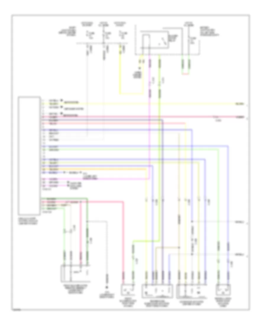
AIR CONDITIONING Manual A/C Wiring Diagram (1 of 2) for Mazda Tribute i Sport 2011 List of elements for Manual A/C Wiring Diagram (1 of 2) for Mazda Tribute i Sport 2011: 30 0740-101 0740-102 Battery junction box (on left side of engine compt) Blower motor relay C-211 C-212 C-237 C-238 Computer data lines system Defogger system Front blower motor (right side of dash) Front blower motor resistor assembly (under right side of dash) Fuse 10a Fuse 40a Fuse 5a G12 (lower right side of dash) G14 (lower left side of dash) Hot at all times Hot in run or acc Hot in run or start J-2280a J-2280b J-2280e Manual climate control module (center of dash) Mode door actuator (center of dash) Recirculation blend door actuator (dash) Seats system Smart junction box (behind center of dash) Temperature blend door actuator (right side of dash) Wiper/ washer system Manual A/C Wiring Diagram (2 of 2) for Mazda Tribute i Sport 2011 List of elements for Manual A/C Wiring Diagram (2 of 2) for Mazda Tribute i Sport 2011: 32 (2.5l) (3.0l) (right front of engine compt) a/c clutch solenoid 0140-175b 0140-175e 0140-275b 0140-275e 2.5l 3.0l A/c clutch relay A/c pressure transducer (left side of engine compt) Ambient air temperature sensor (behind left side of front grille) Battery junction box (on left side of engine compt) C-212 Computer data lines system Cooling fan relay Cylinder head temperature sensor (2.5l: on right front of cylinder head) (3.0l: front center of engine) Engine control system Engine cooling fan motor 1 (front of engine compt) Engine cooling fan motor 2 (front of engine compt) Engine cooling fan resistor Evaporator discharge temperature sensor (right side of dash) Fuse 10a Fuse 40a G11 (left front of engine compt) G3 (right front of engine compt) High speed fan control relay Hot at all times Low speed fan control relay Pcm power relay Powertrain control module (pcm) (upper center of firewall) Red
ANTI-LOCK BRAKES Anti-lock Brakes Wiring Diagram for Mazda Tribute i Sport 2011 List of elements for Anti-lock Brakes Wiring Diagram for Mazda Tribute i Sport 2011: 31 0810-102 Abs control module (left rear of engine compt) Abs test connector Battery junction box (on left side of engine compt) Brake fluid level switch (left rear of engine compt) Brake pedal position switch (on bracket, above brake pedal) C-210 C-212 C-215 Computer data lines system Fuse 15a Fuse 20a Fuse 50a Fuse 5a G11 (left front of engine compt) G14 (lower left side of dash) G5 (left front of engine compt) Hot at all times Hot in run or start J-2280b J-2280d J-2280f Left front wheel speed sensor (left rear hub assembly) Left rear wheel speed sensor (left rear hub assembly) Microcomputer Red Restraints control module Right front wheel speed sensor (right rear hub assembly) Right rear wheel speed sensor (right rear hub assembly) Smart junction box (behind center of dash) Traction assist disable switch
ANTI-THEFT Forced Entry Wiring Diagram (1 of 2) for Mazda Tribute i Sport 2011 List of elements for Forced Entry Wiring Diagram (1 of 2) for Mazda Tribute i Sport 2011: 27 All lock relay All unlock relay C-313 C-314 C-408 C-922 Door ajar Driver side front door lock unit Driver unlock relay Fet Fuse 15a Fuse 20a G18 (near base of left "b" pillar) G19 (base of left "b" pillar) G24 (left rear of vehicle chassis) Horn relay Horns system Hot at all times Hot w/ accessory delay relay energized J-2280b J-2280c J-2280d J-2280e Left rear door lock actuator Liftglass release relay Microcomputer Smart junction box (behind center of dash) Forced Entry Wiring Diagram (2 of 2) for Mazda Tribute i Sport 2011 List of elements for Forced Entry Wiring Diagram (2 of 2) for Mazda Tribute i Sport 2011: 23 C-311 C-312 C-314 C-408 C-410 Door ajar Driver side door lock switch G18 (near base of left "b" pillar) G19 (base of left "b" pillar) G23 (left rear of vehicle chassis) G24 (left rear of vehicle chassis) Left license plate lamp Liftgate ajar switch (on liftgate latch) Liftgate glass ajar switch (base of liftgate) Liftgate glass release switch Liftgate lock actuator Liftgate release switch Lock Passenger side door lock switch Passenger side front door lock unit Right license plate lamp Right rear door lock actuator Unlock Immobilizer Wiring Diagram for Mazda Tribute i Sport 2011 List of elements for Immobilizer Wiring Diagram for Mazda Tribute i Sport 2011: 9 Computer data lines system Floor shifter Fuse 5a G13 (lower right side of dash) Hot in run or start Instrument cluster J-2280b Passive anti-theft transceiver (behind lower left side of dash, near steering column) Smart junction box (behind center of dash)
BODY CONTROL MODULES Body Control Modules Wiring Diagram (1 of 3) for Mazda Tribute i Sport 2011 List of elements for Body Control Modules Wiring Diagram (1 of 3) for Mazda Tribute i Sport 2011: 66 Acc Air conditioning system Anti-lock brakes system Anti-theft system Autolamp on Autolamp sens Back lighting Battery junction box (on left side of engine compt) Brk pedal sw C-211 Computer data lines system Defeat Dim sw gnd Dimmer off Dimmer sw Electronic power steering system Exterior lights & anti-lock brakes systems Exterior lights system Flash to pass Fog lamp Front fog lamp Fuse 14 10a Fuse 15 10a Fuse 20 15a Fuse 26 10a Fuse 27 20a Fuse 28 5a Fuse 29 5a Fuse 31 10a Fuse 34 5a Fuse 35 10a Fuse 36 5a Fuse 37 10a Fuse 39 20a Fuse 40 20a Fuse 43 10a Fuse 46 7.5a Hazard Headlamp off Headlights system High beam Horn relay Horns system Ign sw Ignition switch Instrument cluster system Interior lighting Interior lights system J-2280a J-2280b Key in sw Lo beam Microcomputer Ms can+ Ms can- Off One touch integrated start diode Parklamp on Power distribution system Run Smart junction box (behind center of dash) Sound systems Start Turn left Turn right Warning & shift interlock systems Body Control Modules Wiring Diagram (2 of 3) for Mazda Tribute i Sport 2011 List of elements for Body Control Modules Wiring Diagram (2 of 3) for Mazda Tribute i Sport 2011: 55 Acc delay relay All unlock & lock Battery saver relay Door lock Door locks & anti-theft system Door locks & anti-theft systems Door locks, anti-theft system mirrors & power tops systems Door unlock Dr door ajar Driver unlock relay Engine controls & transmissions system Exterior lights system Exterior lights, cruise control & anti-lock brakes systems Floor shift Fuse 11 10a Fuse 12 7.5a Fuse 18 20a Fuse 19 30a Fuse 2 15a Fuse 32 10a Fuse 35 10a Fuse 38 20a Fuse 4 30a Fuse 41 15a Fuse 43 10a Fuse 46 7.5a G19 (base of left "b" pillar) Headlights, instrument cluster & warning systems Interior lights system J-2280c J-2280d Liftgate ajar sw Liftgate lock Liftgate/glass ajar Liftglass release relay Liftglass sw Logic gnd Lr stop/turn lamp Microcomputer Mirrors system Navigation system Park brake Park lamp relay Power tops system Power windows system Pr door ajar Pwr gnd Rr stop/turn lamp Seats system Shift interlock system Smart junction box (sjb) (behind center of dash) Sound systems Transmissions system Wiper/washer & seats systems Wiper/washer system Body Control Modules Wiring Diagram (3 of 3) for Mazda Tribute i Sport 2011 List of elements for Body Control Modules Wiring Diagram (3 of 3) for Mazda Tribute i Sport 2011: 27 Anti-lock brakes system Battery junction box (bjb) (on left side of engine compt) Brake fluid sw Exterior lights system Fog lamp relay Fuse 27 20a Fuse 45 5a Headlights system High beam relay Horn relay Horns system Hot at all times Ign sw J-2280e J-2280f J-2280g Left low beam Left turn lamp Microcomputer Midi fusible link 125a Park lamp relay Right low beam Right turn lamp Smart junction box (sjb) (behind center of dash) Wiper mtr on input Wiper/washer & air conditioning systems Wiper/washer system
COMPUTER DATA LINES Computer Data Lines Wiring Diagram for Mazda Tribute i Sport 2011 List of elements for Computer Data Lines Wiring Diagram for Mazda Tribute i Sport 2011: 38 (2.5l) (3.0l) 0140-175b 0140-275b 0613-01 0740-101 0810-102 0920-206 Abs control module (left rear of engine compartment) Abs test connector Audio unit C-210 C-212 C-215 C-248 C-263 C-340 Data link connector (dlc) Four-wheel drive control module (near base of driver seat) Front control interface module (center of dash) Front display interface module Fuse 15a G13 (lower right side of dash) G15 (left side of dash) Hot at all times Instrument cluster J-2280a J-2280b Manual climate control module (center of dash) Microcomputer Occupant classification sensor (ocs) (in passenger's seat bottom) Power steering control module (left rear of engine compt) Powertrain control module (upper center of firewall) Restraints control module (rcm) Satellite radio receiver (w/ satellite radio) Smart junction box (behind center of dash) W/ satellite radio W/o satellite radio
COOLING FAN Cooling Fan Wiring Diagram for Mazda Tribute i Sport 2011 List of elements for Cooling Fan Wiring Diagram for Mazda Tribute i Sport 2011: 25 (2.5l) (3.0l) 0140-175b 0140-175e 0140-275b 0140-275e 2.5l 3.0l Battery junction box (bjb) (on left side of engine compt) Computer data lines system Cooling fan relay Cylinder head temperature sensor (2.5l: on right front of cylinder head) (3.0l: front center of engine) Engine control system Engine cooling fan motor 1 (front of engine compt) Engine cooling fan motor 2 (front of engine compt) Engine cooling fan resistor Fuse 10a Fuse 40a G3 (right front of engine compt) High speed fan control relay Hot at all times Low speed fan control relay Pcm power relay Powertrain control module (pcm) (upper center of firewall) Red
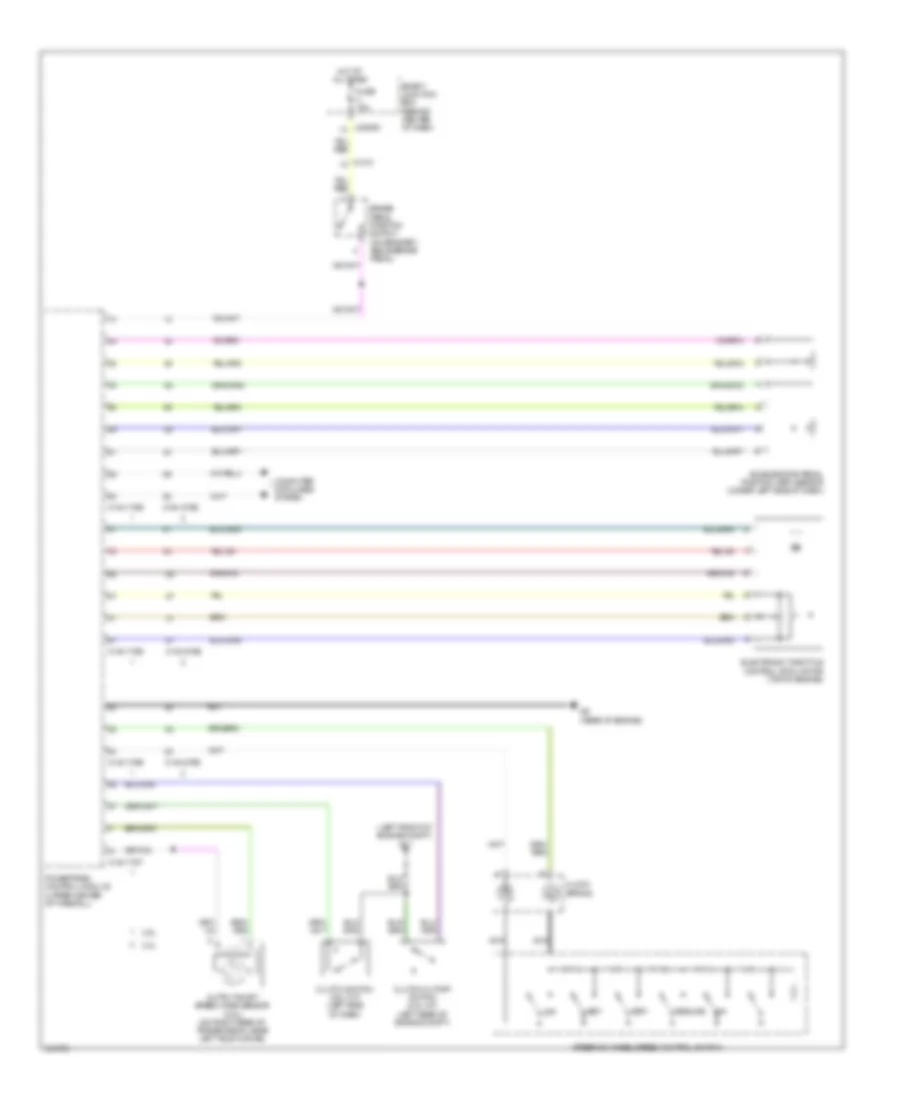
CRUISE CONTROL Cruise Control Wiring Diagram for Mazda Tribute i Sport 2011 List of elements for Cruise Control Wiring Diagram for Mazda Tribute i Sport 2011: 29 (left front of engine compt) g11 0140-175b 0140-175e 0140-175t 0140-275b 0140-275e 2.5l 3.0l Accelerator pedal position (app) sensor (under left side of dash) Brake pedal position switch (on bracket, above brake pedal) C-210 Clock spring Clutch cutoff switch (2.5l m/t) (left rear of engine compt) Clutch switch (2.5l m/t) (left side of dash) Computer data lines system Electronic throttle control (etc) motor (top of engine) Fuse 15a G9 (rear of engine) Hot at all times J-2280d Nca Off Output shaft speed (oss) sensor (2.5l) (on right rear of transmission, near left axle flange) Powertrain control module (upper center of firewall) Resume Set+ Set- Smart junction box (behind center of dash) Steering wheel/speed control switch
DEFOGGERS Defoggers Wiring Diagram for Mazda Tribute i Sport 2011 List of elements for Defoggers Wiring Diagram for Mazda Tribute i Sport 2011: 23 0740-101 0912-102 0912-103 Battery junction box (on left side of engine compt) C-210 C-212 C-312 C-314 C-405 C-913 Driver side extended rear view mirror Fuse 10a Fuse 15a Fuse 30a G19 (base of left "b" pillar) G23 (left rear of vehicle chassis) G24 (left rear of vehicle chassis) Hot at all times Hot in run or start Manual climate control module (center of dash) Passenger side extended rear view mirror Rear window defrost grid Rear window defrost relay
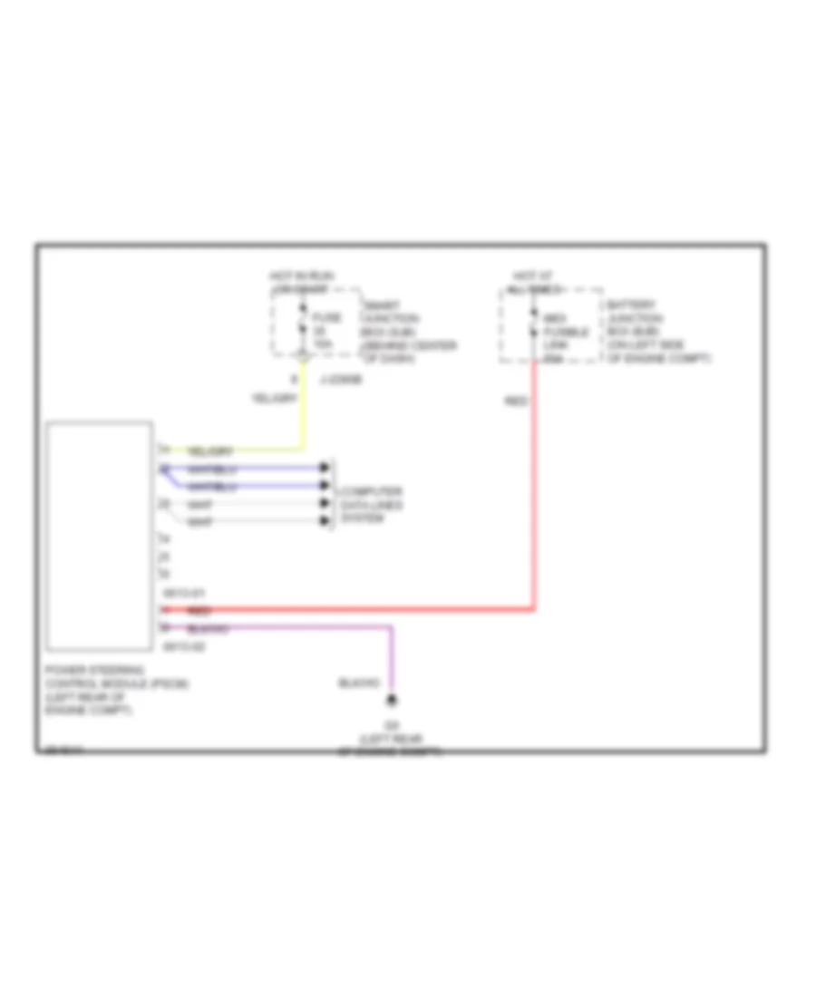
ELECTRONIC POWER STEERING Electronic Power Steering Wiring Diagram for Mazda Tribute i Sport 2011 List of elements for Electronic Power Steering Wiring Diagram for Mazda Tribute i Sport 2011: 13 0613-01 0613-02 Battery junction box (bjb) (on left side of engine compt) Computer data lines system Fuse 10a G6 (left rear of engine compt) Hot at all times Hot in run or start J-2280b Midi fusible link 80a Power steering control module (pscm) (left rear of engine compt) Red Smart junction box (sjb) (behind center of dash)
ENGINE PERFORMANCE
2.5L 2.5L, Engine Performance Wiring Diagram (1 of 4) for Mazda Tribute i Sport 2011 List of elements for 2.5L, Engine Performance Wiring Diagram (1 of 4) for Mazda Tribute i Sport 2011: 25 (top of engine) (top of engine) electronic throttle control motor 0140-175e Acc C-211 Camshaft position sensor (on left rear of cylinder head) Coil on plug 1 (top right of engine) Coil on plug 2 (top right of engine) Coil on plug 3 (top right of engine) Coil on plug 4 (top left of engine) Crankshaft position sensor (front of engine block) Cylinder head temperature (cht) sensor (on right front of cylinder head) Fuel injector 1 Fuel injector 2 Fuel injector 3 Fuel injector 4 Hot at all times Ignition switch Ignition transformer capacitor (on top of engine) Knock sensor Manifold absolute pressure (map) sensor (front of engine compt) Off Powertrain control module (pcm) (upper center of firewall) Run Start 2.5L, Engine Performance Wiring Diagram (2 of 4) for Mazda Tribute i Sport 2011 List of elements for 2.5L, Engine Performance Wiring Diagram (2 of 4) for Mazda Tribute i Sport 2011: 22 (left front of engine compt) g11 (rear of engine compt) A/t Battery junction box (on left side of engine compt) C-133 Egr stepper motor (left rear of engine) Evaporative emission (evap) canister purge valve (rear of engine compt) Fuel injector relay Fuel pump diode Fuel pump relay Fuse 10a Fuse 15a Fuse 20a G11 (left front of engine compt) Heated oxygen sensor (ho2s) 11 (a/t) (right side of engine) Heated oxygen sensor (ho2s) 11 (m/t) (right side of engine) Heated oxygen sensor (ho2s) 12 Hot at all times M/t Output shaft speed (oss) sensor (m/t) (on right rear of transmission, near left axle flange) Pcm power relay Variable camshaft timing (vct) valve (top front of engine) 2.5L, Engine Performance Wiring Diagram (3 of 4) for Mazda Tribute i Sport 2011 List of elements for 2.5L, Engine Performance Wiring Diagram (3 of 4) for Mazda Tribute i Sport 2011: 13 (under center of vehicle) evap canister vent control solenoid (under left rear of vehicle, above fuel tank) fuel tank pressure transducer sensor 0140-131 0140-132 0140-175t C-210 C-212 C-327 Exterior lights system Floor shifter Powertrain control module (pcm) (upper center of firewall) Transmission Transmission control switch 2.5L, Engine Performance Wiring Diagram (4 of 4) for Mazda Tribute i Sport 2011 List of elements for 2.5L, Engine Performance Wiring Diagram (4 of 4) for Mazda Tribute i Sport 2011: 22 (behind right kick panel) inertia fuel shutoff (ifs) switch (left rear of engine compt) (m/t) clutch cutoff switch (left side of dash) (m/t) clutch switch (top of fuel tank) 0140-175b Accelerator pedal position (app) sensor (under left side of dash) Air conditioning system C-215 Computer data lines system Cooling fans system Cruise control system Exterior lights system starting/charging system Fuel pump relay Fuel tank unit G11 (left front of engine compt) G22 (left rear c-210 G9 (rear of engine) Instrument cluster Mass air flow/ intake air temperature (maf/iat) sensor (near rear of cylinder head, in air intake duct) Powertrain control module (pcm) (upper center of firewall) Quarterpanel) Starting/charging system
3.0L 3.0L, Engine Performance Wiring Diagram (1 of 5) for Mazda Tribute i Sport 2011 List of elements for 3.0L, Engine Performance Wiring Diagram (1 of 5) for Mazda Tribute i Sport 2011: 19 (top left of engine) (top right of engine) (top right of engine) fuel injector 1 0140-275e C-110 Coil on plug 1 (top right of engine) Coil on plug 2 (top right of engine) Coil on plug 3 (top right of engine) Coil on plug 4 (top left of engine) Coil on plug 5 (top left of engine) Coil on plug 6 (top left of engine) Crankshaft position sensor (front of engine) Fuel injector 2 Fuel injector 3 Fuel injector 4 Fuel injector 5 Fuel injector 6 Ignition transformer capacitor (on top of engine) Powertrain control module (pcm) (upper center of firewall) 3.0L, Engine Performance Wiring Diagram (2 of 5) for Mazda Tribute i Sport 2011 List of elements for 3.0L, Engine Performance Wiring Diagram (2 of 5) for Mazda Tribute i Sport 2011: 20 (left rear of engine compt) (m/t) clutch cutoff switch (left side of dash) (m/t) clutch switch (top of engine) electronic throttle control (etc) motor Acc C-211 C-212 Camshaft position sensor 1 (on front of left cylinder head) Camshaft position sensor 2 (on front of right cylinder head) Cylinder head temperature (cht) sensor (front center of engine) Floor shifter G11 (left front of engine compt) Hot at all times Ignition switch Knock sensor 1 (left rear of engine) Knock sensor 2 (right rear of engine) Manifold absolute pressure (map) sensor (right rear of engine compt) Off Run Start Transmission control switch 3.0L, Engine Performance Wiring Diagram (3 of 5) for Mazda Tribute i Sport 2011 List of elements for 3.0L, Engine Performance Wiring Diagram (3 of 5) for Mazda Tribute i Sport 2011: 25 (front of engine compt) (left front of engine compt) (right rear of engine compt) Battery junction box (on left side of engine compt) C-110 C-133 Egr stepper motor (left rear of engine) Evaporative emission (evap) canister purge valve (rear of engine compt) Fuel injector relay Fuel pump diode Fuel pump relay Fuse 10a Fuse 15a Fuse 20a G11 (left front of engine compt) Heated oxygen sensor (ho2s) 11 (right side of engine compt) Heated oxygen sensor (ho2s) 12 Heated oxygen sensor (ho2s) 21 Heated oxygen sensor (ho2s) 22 Hot at all times Pcm power relay Variable camshaft timing (vct) valve 1 (top front of engine) Variable camshaft timing (vct) valve 2 (top of engine) W/ floor shift W/o floor shift 3.0L, Engine Performance Wiring Diagram (4 of 5) for Mazda Tribute i Sport 2011 List of elements for 3.0L, Engine Performance Wiring Diagram (4 of 5) for Mazda Tribute i Sport 2011: 11 (rear of engine) heated positive crankcase ventilation (pcv) valve (under center of vehicle) evap canister vent control solenoid (under left rear of vehicle, above fuel tank) fuel tank pressure transducer sensor 0140-231 0140-232 0140-275t C-210 C-327 Exterior lights system Powertrain control module (pcm) (upper center of firewall) Transmission 3.0L, Engine Performance Wiring Diagram (5 of 5) for Mazda Tribute i Sport 2011 List of elements for 3.0L, Engine Performance Wiring Diagram (5 of 5) for Mazda Tribute i Sport 2011: 18 (behind right kick panel) inertia fuel shutoff (ifs) switch (top of fuel tank) fuel tank unit 0140-275b Accelerator pedal position (app) sensor (under left side of dash) Air conditioning system C-215 Computer data lines system Cooling fans system Cruise control system Exterior lights system Fuel pump relay G22 (left rear c-210 G9 (rear of engine) Instrument cluster Mass air flow/ intake air temperature (maf/iat) sensor (left side of engine compt) Powertrain control module (pcm) (upper center of firewall) Quarterpanel) Starting/charging system
EXTERIOR LIGHTS Backup Lamps Wiring Diagram for Mazda Tribute i Sport 2011 List of elements for Backup Lamps Wiring Diagram for Mazda Tribute i Sport 2011: 15 0140-175t A/t Battery junction box (on left side of engine compt) C-210 Fuse 10a G11 (left front of engine compt) G19 (base of left "b" pillar) Hot in run or start Hot w/ pcm power relay energized Left reverse lamp M/t Powertrain control module (pcm) (upper center of firewall) Reverse lamp relay Reversing lamp switch (top of transmission) Right reverse lamp Exterior Lamps Wiring Diagram (1 of 2) for Mazda Tribute i Sport 2011 List of elements for Exterior Lamps Wiring Diagram (1 of 2) for Mazda Tribute i Sport 2011: 37 Auto Brake sw C2280e Computer data lines system Ftp Fuse 15a Fuse 20a G11 (left front of engine compt) G15 (left side of dash) Hazard High beam Hot at all times J-2280b J-2280d J-2280f Left front park/ turn lamp Lf turn Lf turn lamp (fet) Lh turn Lo beam Lr stop/ turn lamp Lr stop/ turn lamp (fet) Main light switch Microcomputer Ms can + Ms can - Off Park Park lamp on Park lamp relay Rf turn Rf turn lamp (fet) Rh turn Right front park/ turn lamp Rr stop/ turn lamp Rr stop/ turn lamp (fet) Smart junction box (behind center of dash) Exterior Lamps Wiring Diagram (2 of 2) for Mazda Tribute i Sport 2011 List of elements for Exterior Lamps Wiring Diagram (2 of 2) for Mazda Tribute i Sport 2011: 42 (upper center of firewall) powertrain control module 0140-175b 0140-275b 3.0l Battery junction box (on left side of engine compt) Brake pedal position switch (on bracket, above brake pedal) C-210 C-215 C-408 C-410 C-421 C-913 C-922 Connector Except 3.0l Ftp Ftp switch Fuse 15a Fuse 20a G11 (left front of engine compt) G14 (lower left side of dash) G20 (right kick panel) G23 (left rear of vehicle chassis) G24 (left rear of vehicle chassis) Hazard switch High High mounted stop lamp Hot at all times Left license plate lamp Left rear park/stop/ turn lamp Low Multi- function switch On/off Red Rest Right license plate lamp Right rear park/stop/ turn lamp Trailer tow Trailer tow left turn relay Trailer tow park lamp relay Trailer tow right turn relay Turn signal switch
GROUND DISTRIBUTION Ground Distribution Wiring Diagram (1 of 2) for Mazda Tribute i Sport 2011 List of elements for Ground Distribution Wiring Diagram (1 of 2) for Mazda Tribute i Sport 2011: 36 (m/t) & (m/t), A/c clutch solenoid, right headlamp, right front fog lamp & right front park/turn lamp Abs control module Battery Battery junction box & engine cooling fan motor 1 Front control interface module, audio unit, satellite radio receiver & audio amplifier (w/ navigation) Fuel pump relay & Fuel pump relay, abs test connector, brake fluid level switch, trailer tow left turn relay, clutch cut off switch clutch switch windshield wiper motor Fuel tank unit shield G1 (3.0l: left rear of engine compt) (2.5l: left side of engine compt) G11 (left front of engine compt) G12 (lower right side of dash) G13 (lower right side of dash) G14 (lower left side of dash) G15 (left side of dash) G17 (center of dash) G2 (right front of engine compt) G22 (left rear quarterpanel) G25 (right rear quarter panel) G3 (right front of engine compt) G4 (right front of engine compt) G5 (left front of engine compt) G6 (left rear of engine compt) G7 (right front of engine compt) G8 (front of engine) G9 (rear of engine) Main light switch, data link connector & instrument cluster Manual climate control module & front blower motor resistor assembly Passive anti-theft transceiver, power point, floor shifter, main light switch, clock spring, instrument cluster & datalink connector Power steering control module Powertrain control module & mass air flow/intake air temperature (maf/iat) sensor Subwoofer amplifier (w/ premium audio) Traction assist disable switch, multi function switch manual climate control module, auto lamp sensor & front display interface module Trailer tow right turn relay, left headlamp, left front park/turn lamp, left front fog lamp, horn, fuel injector relay & reversing lamp switch Windshield wiper motor Ground Distribution Wiring Diagram (2 of 2) for Mazda Tribute i Sport 2011 List of elements for Ground Distribution Wiring Diagram (2 of 2) for Mazda Tribute i Sport 2011: 27 Driver seat position sensor & driver seat belt buckle switch Driver side door lock switch Driver side front door lock unit, master window adjust switch & driver side extended rearview mirror Extended rearview mirror switch G18 (near base of left "b" pillar) G19 (base of left "b" pillar) G20 (right kick panel) G21 (right front kick panel) G23 (left rear of vehicle chassis) G24 (left rear of vehicle chassis) High mounted stop lamp & rear wiper motor assembly Left power seat switch & driver side front heated seat element Left rear door lock actuator & rear view camera Left rear park/ stop turn lamp, right rear park/ stop turn lamp & console power point Liftgate glass ajar switch Liftgate lock actuator Passenger seat belt buckle switch & occupant classification sensor (ocs) Passenger side door lock switch Passenger side front door lock unit & passenger side extended rearview mirror Passenger side front heated seat element, intelligent 4wd system module, left reversing lamp, cargo lamp & smart junction box Rear window defrost grid Rear wiper motor assembly & trailer tow connector Right license plate lamp, liftgate glass release switch, left license plate lamp & liftgate release switch Right rear door lock actuator Right reversing lamp & smart junction box Roof opening panel control module, left vanity mirror lamp, right vanity mirror lamp, front interor/ map lamps assembly (w/ roof opening panel) & front interior lamp Safety belt tension sensor
HEADLIGHTS Headlights Wiring Diagram for Mazda Tribute i Sport 2011 List of elements for Headlights Wiring Diagram for Mazda Tribute i Sport 2011: 45 (w/o drl) Auto 1 Auto on Auto- lp in Autolamp sensor (w/o drl) Computer data lines system Flash to pass Fog Fog ind Fog lamp relay Fog lp Ftp Fuse 10a Fuse 15a G11 (left front of engine compt) G14 (lower left side of dash) G15 (left side of dash) G18 (near base of left "b" pillar) High beam High beam relay Hot at all times Instrument cluster Interior lights system J-2280a J-2280b J-2280c J-2280e Left front fog lamp Left headlamp Left low beam (fet) Low Main light switch Microcomputer Ms can+ Ms can- Multi-function switch Off Park Park brake switch (w/ drl) Park brk Park on Right front fog lamp Right headlamp Right low beam (fet) Smart junction box (behind center of dash)
HORN Horn Wiring Diagram for Mazda Tribute i Sport 2011 List of elements for Horn Wiring Diagram for Mazda Tribute i Sport 2011: 13 Clock spring Fuse 20a G11 (left front of engine compt) G13 (lower right side of dash) Horn (left front corner of engine compt) Horn relay Horn switch Hot at all times J-2280b J-2280e Microcomputer Nca Smart junction box (behind center of dash)
INSTRUMENT CLUSTER Instrument Cluster Wiring Diagram for Mazda Tribute i Sport 2011 List of elements for Instrument Cluster Wiring Diagram for Mazda Tribute i Sport 2011: 42 Ajar Anti-theft system Brake fluid level switch (left rear of engine compt) C-133 C-212 C-215 C-311 C-312 C-313 C-314 C-408 C-922 Computer data lines system Driver side front door lock unit Fuel tank unit (top of fuel tank) Fuse 10a Fuse 5a G11 (left front of engine compt) G13 (lower right side of dash) G15 (left side of dash) G18 (near base of left "b" pillar) G19 (base of left "b" pillar) G24 (left rear of vehicle chassis) Hot at all times Hot in run or acc Hot in start or run Instrument cluster J-2280a J-2280b J-2280c J-2280d J-2280f Left rear door lock actuator Liftgate ajar switch (on liftgate latch) Liftgate glass ajar switch (base of liftgate) Main light switch Microcomputer Mirrors system Oil pressure switch Passenger side front door lock unit Right rear door lock actuator Smart junction box (behind center of dash)
INTERIOR LIGHTS Courtesy Lamps Wiring Diagram for Mazda Tribute i Sport 2011 List of elements for Courtesy Lamps Wiring Diagram for Mazda Tribute i Sport 2011: 36 0918-805 0918-806 Battery saver relay C-214 C-215 C-311 C-312 C-313 C-314 C-408 C-922 Cargo lamp Driver side front door lock unit Front interior lamp (w/ roof opening panel) Front interior lamp (w/o roof opening panel) Front interior/ map lamps assembly (w/ roof opening panel) Fuse 10a Fuse 15a G18 (near base of left "b" pillar) G19 (base of left "b" pillar) G24 (left rear of vehicle chassis) Hot at all times Interior lighting (fet) J-2280a J-2280c J-2280d Left rear door lock actuator Left vanity mirror lamp Liftgate ajar switch (on liftgate latch) Liftgate glass ajar switch (base of liftgate) Microcomputer Off Passenger side front door lock unit Right rear door lock actuator Right vanity mirror lamp Smart junction box (behind center of dash) Instrument Illumination Wiring Diagram for Mazda Tribute i Sport 2011 List of elements for Instrument Illumination Wiring Diagram for Mazda Tribute i Sport 2011: 24 Audio/climate control switch Auto 1 Backlighting led (fet) Clock spring Defeat Dim Floor shifter Fuse 15a G13 (lower right side of dash) G14 (lower left side of dash) G15 (left side of dash) Hot at all times Illumination dimmer J-2280b Low Main light switch Microcomputer Nca Off Off dim Park Smart junction box (behind center of dash) Steering wheel/ speed control switch Traction assist disable switch
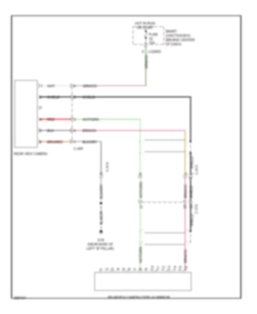
NAVIGATION Navigation Wiring Diagram (1 of 2) for Mazda Tribute i Sport 2011 List of elements for Navigation Wiring Diagram (1 of 2) for Mazda Tribute i Sport 2011: 25 (center of dash) 0920-201 0920-206 0922-202 Audio jack Audio unit C-248 Clock spring Computer data Fuse 25a Fuse 5a G17 Hot at all times Hot in start J-2280a J-2280b Lines system Media Seek+ Seek- Shield Smart junction box (behind center of dash) Steering wheel/ audio control switch Vol+ Vol- Navigation Wiring Diagram (2 of 2) for Mazda Tribute i Sport 2011 List of elements for Navigation Wiring Diagram (2 of 2) for Mazda Tribute i Sport 2011: 15 0920-406a 0920-406b Audio amplifier C-264 C-311 C-312 C-313 C-314 C-316 G17 (center of dash) Left front speaker Left rear speaker Right front speaker Right rear speaker Shield Rear View Camera Wiring Diagram for Mazda Tribute i Sport 2011 List of elements for Rear View Camera Wiring Diagram for Mazda Tribute i Sport 2011: 13 C-316 C-495 C-913 C-914 Fuse 10a G18 (near base of left "b" pillar) Hot in run or start J-2280d Rear view camera Rearview camera display mirror Red Shield Smart junction box (behind center of dash)
POWER DISTRIBUTION Power Distribution Wiring Diagram (1 of 2) for Mazda Tribute i Sport 2011 List of elements for Power Distribution Wiring Diagram (1 of 2) for Mazda Tribute i Sport 2011: 57 (left rear of vehicle chassis) 175a 2.5l 20a 3.0l Accessory delay relay Air conditioning system Anti-lock brakes system Anti-lock brakes, cruise control & exterior lights systems Battery Battery junction box (on left side of engine compt) C-210 C-3007 Circuit breaker 30a Computer data lines system Console power point Cooling fans system Defogger system Door locks & anti-theft systems Door locks, anti-theft, mirrors & power tops systems Electronic power steering system Engine controls system Exterior lights & defogger systems Exterior lights & engine controls systems Exterior lights system From a fuse 14 (diagram 1 of 2) From ignition switch (diagram 2 of 2) Fuse Fuse 10a Fuse 15a Fuse 20a Fuse 30a Fuse 40a Fuse 50a Fuse 7.5a Fusible link G23 Horns system J-2280a J-2280d J-2280g Micro computer Midi fusible link 125a Midi fusible link 80a Mirrors system Power tops system Power windows system Red Seats system Shift interlock system Smart junction box (behind center of dash) Starting/ charging & transmissions systems Starting/ charging system To fuse 18 (diagram 1 of 2) To fuse 7 (diagram 2 of 2) Transmissions system Wiper/ washer system Power Distribution Wiring Diagram (2 of 2) for Mazda Tribute i Sport 2011 List of elements for Power Distribution Wiring Diagram (2 of 2) for Mazda Tribute i Sport 2011: 42 Acc Air conditioning & wiper/washer systems Air conditioning system Anti-lock brakes system Anti-theft system C-211 Electronic power steering system Engine controls system Exterior lights system From b fuse 17 (diagram 1 of 2) Fuse 10a Fuse 15a Fuse 20a Fuse 30a Fuse 5a Fuse 7.5a G13 (lower right side of dash) Headlights system Ignition switch Instrument cluster system Interior lights system J-2280a J-2280b J-2280d J-2280e Key in ignition Key in ignition switch Lock solenoid Micro computer Navigation system Off Power point Run Shift interlock & power tops systems Smart junction box (behind center of dash) Sound systems Start Starting/ charging, engine controls & sounds systems To battery junction box (diagram 1 of 2) Transmissions system Wiper/ washer & seats systems Wiper/ washer system
POWER DOOR LOCKS Power Door Locks Wiring Diagram (1 of 2) for Mazda Tribute i Sport 2011 List of elements for Power Door Locks Wiring Diagram (1 of 2) for Mazda Tribute i Sport 2011: 27 All lock relay All unlock relay C-313 C-314 C-408 C-922 Door ajar Driver side front door lock unit Driver unlock relay Fet Fuse 15a Fuse 20a G18 (near base of left "b" pillar) G19 (base of left "b" pillar) G24 (left rear of vehicle chassis) Horn relay Horns system Hot at all times Hot w/ accessory delay relay energized J-2280b J-2280c J-2280d J-2280e Left rear door lock actuator Liftglass release relay Microcomputer Smart junction box (behind center of dash) Power Door Locks Wiring Diagram (2 of 2) for Mazda Tribute i Sport 2011 List of elements for Power Door Locks Wiring Diagram (2 of 2) for Mazda Tribute i Sport 2011: 23 C-311 C-312 C-314 C-408 C-410 Door ajar Driver side door lock switch G18 (near base of left "b" pillar) G19 (base of left "b" pillar) G23 (left rear of vehicle chassis) G24 (left rear of vehicle chassis) Left license plate lamp Liftgate ajar switch (on liftgate latch) Liftgate glass ajar switch (base of liftgate) Liftgate glass release switch Liftgate lock actuator Liftgate release switch Lock Passenger side door lock switch Passenger side front door lock unit Right license plate lamp Right rear door lock actuator Unlock
POWER MIRRORS Power Mirror Wiring Diagram for Mazda Tribute i Sport 2011 List of elements for Power Mirror Wiring Diagram for Mazda Tribute i Sport 2011: 15 C-312 C-314 Defogger system Down Driver side exterior rear view mirror Exterior rear view mirror switch Fuse 7.5a G24 (left rear of vehicle chassis) Hot at all times J-2280d Left Passenger side exterior rear view mirror Right Select Smart junction box (sjb) (behind center of dash)
POWER SEATS Heated Seats Wiring Diagram for Mazda Tribute i Sport 2011 List of elements for Heated Seats Wiring Diagram for Mazda Tribute i Sport 2011: 16 0740-101 C-215 C-339 C-340 Driver heated seat relay Driver side front heater seat element Fuse 10a Fuse 20a G19 (base of left "b" pillar) Hot at all times Hot in run or acc J-2280d Manual climate control module (center of dash) Passenger heated seat relay Passenger side front heater seat element Smart junction box (behind center of dash) Power Seat Wiring Diagram for Mazda Tribute i Sport 2011 List of elements for Power Seat Wiring Diagram for Mazda Tribute i Sport 2011: 16 Back Battery junction box (on left side of engine compt) C-210 C-339 Down Front Front up/down Fuse 30a Fwd Fwd/back G19 (base of left "b" pillar) Hot at all times Left power seat motor assembly Left power seat switch Rear Rear up/down
POWER TOP/SUNROOF Power Top/Sunroof Wiring Diagram for Mazda Tribute i Sport 2011 List of elements for Power Top/Sunroof Wiring Diagram for Mazda Tribute i Sport 2011: 25 (lower right side of dash) g13 Acc rly Accessory delay relay Auto Battery C-214 Close Common Floor shifter Fuse 15a Fuse 20a Fuse 30a G19 (base of left "b" pillar) Gnd Hot at all times Ign Ignition switch J-2280a J-2280d Micro- computer Open Park range Roof opening panel control module (front center of roof) Roof opening panel control switch Smart junction box (behind center of dash)
POWER WINDOWS Power Windows Wiring Diagram for Mazda Tribute i Sport 2011 List of elements for Power Windows Wiring Diagram for Mazda Tribute i Sport 2011: 33 0912-201a 0912-201b Accessory delay relay Auto dn Auto dn circuit Battery junction box (on left side of engine compt) C-311 C-312 C-313 C-314 Circuit breaker 30a Down relay Driver Front driver side power window motor (in left front door) Front passenger side power window motor (in right front door) G24 (left rear of vehicle chassis) Hot at all times J-2280g J2280d Left rear Left rear power window motor (in left rear door) Left rear window adjust switch Master window adjust switch Micro computer Midi fusible link 125a Pass Passenger side window adjust switch Right rear Right rear power window motor (in right rear door) Right rear window adjust switch Sensing resistor Smart junction box (behind center of dash) Window lockout
RADIO Radio Wiring Diagram, Base without Navigation for Mazda Tribute i Sport 2011 List of elements for Radio Wiring Diagram, Base without Navigation for Mazda Tribute i Sport 2011: 31 0920-201 0920-206 Audio jack Audio unit C-248 C-311 C-312 C-313 C-314 C-316 Clockspring Computer data lines system Fuse 20a Fuse 5a G17 (center of dash) Hot at all times Hot in start J-2280a J-2280b Left front speaker Left rear speaker Media Nca Right front speaker Right rear speaker Seek + Seek - Smart junction box (behind center of dash) Steering wheel/audio control switch Vol+ Vol- Radio Wiring Diagram, Premium without Navigation for Mazda Tribute i Sport 2011 List of elements for Radio Wiring Diagram, Premium without Navigation for Mazda Tribute i Sport 2011: 41 0920-201 0920-206 0920-207 Audio jack Audio unit C-248 C-263 C-311 C-312 C-313 C-314 C-316 Clockspring Computer data lines system Front control interface module (center of dash) Front display interface module Fuse 10a Fuse 20a Fuse 5a G14 (lower left side of dash) G17 (center of dash) G25 (right rear quarter panel) Hot at all times Hot in start J-2280a J-2280b J-2280d Left front speaker Left rear speaker Media Nca Right front speaker Right rear speaker Satellite radio receiver Seek + Seek - Smart junction box (behind center of dash) Steering wheel/audio control switch Subwoofer amplifier Vol+ Vol- Radio Wiring Diagram, with Navigation (1 of 2) for Mazda Tribute i Sport 2011 List of elements for Radio Wiring Diagram, with Navigation (1 of 2) for Mazda Tribute i Sport 2011: 25 (center of dash) 0920-201 0920-206 0922-202 Audio jack Audio unit C-248 Clock spring Computer data Fuse 25a Fuse 5a G17 Hot at all times Hot in start J-2280a J-2280b Lines system Media Seek+ Seek- Shield Smart junction box (behind center of dash) Steering wheel/ audio control switch Vol+ Vol- Radio Wiring Diagram, with Navigation (2 of 2) for Mazda Tribute i Sport 2011 List of elements for Radio Wiring Diagram, with Navigation (2 of 2) for Mazda Tribute i Sport 2011: 15 0920-406a 0920-406b Audio amplifier C-264 C-311 C-312 C-313 C-314 C-316 G17 (center of dash) Left front speaker Left rear speaker Right front speaker Right rear speaker Shield
SHIFT INTERLOCK Shift Interlock Wiring Diagram for Mazda Tribute i Sport 2011 List of elements for Shift Interlock Wiring Diagram for Mazda Tribute i Sport 2011: 22 Brake pedal position switch (on bracket, above brake pedal) C-215 Computer data lines system Fet Floor shifter Fuse 2 15a Fuse 27 20a Fuse 5 10a G13 (lower right side of dash) Hot at all times Ignition switch Interior lights system J-2280a J-2280b J-2280c J-2280d Key in ignition Lock Microcomputer Park range Shift lock solenoid Smart junction box (sjb) (behind center of dash)
STARTING/CHARGING Charging Wiring Diagram for Mazda Tribute i Sport 2011 List of elements for Charging Wiring Diagram for Mazda Tribute i Sport 2011: 26 (2.5l) (3.0l) 0140-275b 0410-175b 175a 2.5l 3.0l Battery Battery junction box (on left side of engine compt) C-140 Computer data lines system Fuse 15a Fuse 5a Fusible link G1 (3.0l: left rear of engine compt) (2.5l: left side of engine compt) G2 (right front of engine compt) Generator Hot in run or start Instrument cluster J-2280b O140-175b Power distribution system Powertrain control module (upper center of firewall) Red Smart junction box (behind center of dash) Starter motor Starting Wiring Diagram for Mazda Tribute i Sport 2011 List of elements for Starting Wiring Diagram for Mazda Tribute i Sport 2011: 30 (2.5l) (3.0l) Acc Battery Battery junction box (on left side of engine compt) C-139 C-211 Charging circuit Fuse 20a Fuse 30a G1 (3.0l: left rear of engine compt) (2.5l: left side of engine compt) G2 (right front of engine compt) Ignition switch J-2280a J-2280b J-2280g Logic Midi fusible link 125a O140-175b O140-275b Off One touch integrated start diode Power distribution system Powertrain control module (upper center of firewall) Red Run Smart junction box (sjb) (behind center of dash) Start Starter motor Starter relay
SUPPLEMENTAL RESTRAINTS Supplemental Restraints Wiring Diagram (1 of 2) for Mazda Tribute i Sport 2011 List of elements for Supplemental Restraints Wiring Diagram (1 of 2) for Mazda Tribute i Sport 2011: 31 0810-101 0810-102 0810-111 0810-112 C-210 C-339 C-340 Clock spring Computer data lines system Driver seat belt buckle switch Driver seat position sensor (under driver's seat bottom) Driver side air bag module Driver side impact sensor 1 (w/ side air curtain) (left "b" pillar) Fuse 10a Fuse 7.5a G21 (right front kick panel) Hot in run or start Inflator 1 Inflator 2 Instrument cluster J-2280b J-2280d Nca Passenger air bag deactivation indicator Passenger seat belt buckle switch Passenger side air bag module Passenger side impact sensor 2 (w/ side air curtain) (right "b" pillar) Restraints control module Right front impact sensor (front of engine compt) Shorting bar Smart junction box (behind center of dash) Supplemental Restraints Wiring Diagram (2 of 2) for Mazda Tribute i Sport 2011 List of elements for Supplemental Restraints Wiring Diagram (2 of 2) for Mazda Tribute i Sport 2011: 26 (below driver's front seat cushion) driver safety belt retractor pretensioner (right front kick panel) g21 Abs control module (left rear of engine compt) C-210 C-339 C-340 Computer Computer data lines system Data lines system Driver safety belt buckle pretensioner Driver side impact sensor 2 (w/ side air curtain) (left "b" pillar) G21 (right front kick panel) Inflator Left front impact sensor (front of engine compt) Left safety canopy (w/ side air curtain) Left side air bag module (w/ side air curtain) Nca Occupant classification sensor (ocs) (in passenger's seat bottom) Passenger safety belt buckle pretensioner Passenger safety belt retractor pretensioner Passenger side impact sensor 1 (w/ side air curtain) (right "b" pillar) Right safety canopy (w/ side air curtain) Right side air bag module (w/ side air curtain) Safety belt tension sensor (passenger's "b" pillar) Seat pressure sensor (in passenger seat bottom) Shorting bar
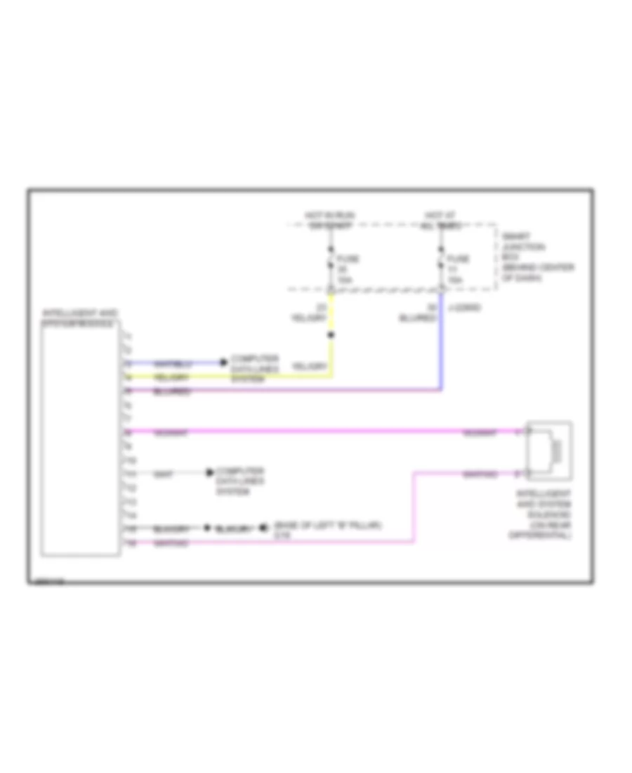
TRANSMISSION 4WD Wiring Diagram for Mazda Tribute i Sport 2011 List of elements for 4WD Wiring Diagram for Mazda Tribute i Sport 2011: 9 (base of left "b" pillar) g19 Computer data lines system Fuse 10a Hot at all times Hot in run or start Intelligent 4wd system module Intelligent 4wd system solenoid (on rear differential) J-2280d Smart junction box (behind center of dash) A/T Wiring Diagram for Mazda Tribute i Sport 2011 List of elements for A/T Wiring Diagram for Mazda Tribute i Sport 2011: 24 (2.5l) (3.0l) (on bracket, above brake pedal) brake pedal position switch 0140-131 0140-132 0140-175b 0140-175t 0140-231 0140-232 0140-275b 0140-275t Battery junction box (on left side of engine compt) C-212 Engine controls system Floor shifter Fuse 10a Fuse 15a G9 (rear of engine) Hot at all times Output shaft speed (oss) sensor (2.5l m/t) (on right rear of transmission, near left axle flange) Pcm power relay Powertrain control module (pcm) (upper center of firewall) Transmission Transmission control switch
TRUNK, TAILGATE, FUEL DOOR Liftgate Release Wiring Diagram for Mazda Tribute i Sport 2011 List of elements for Liftgate Release Wiring Diagram for Mazda Tribute i Sport 2011: 21 C-408 C-410 C-922 Fet Fuse 20a G18 (near base of left "b" pillar) G23 (left rear of vehicle chassis) G24 (left rear of vehicle chassis) Hot at all times J-2280c J-2280d Left license plate lamp Liftgate ajar switch (on liftgate latch) Liftgate glass ajar switch (base of liftgate) Liftgate glass release switch Liftgate lock actuator Liftgate release switch Liftglass release relay Microcomputer Right license plate lamp Smart junction box (behind center of dash)
WARNING SYSTEMS Warning Systems Wiring Diagram for Mazda Tribute i Sport 2011 List of elements for Warning Systems Wiring Diagram for Mazda Tribute i Sport 2011: 50 (base of left "b" pillar) g19 0810-102 Abs control module (left rear of engine compt) Auto 1 Brake fluid level switch (left rear of engine compartment) C-311 C-312 C-313 C-314 C-408 C-922 Computer data lines system Driver seat belt buckle switch Driver side front door lock unit Fuse 10a Fuse 20a Fuse 5a G11 (left front of engine compt) G13 (lower right side of dash) G15 (left side of dash) G18 (base of left "b" pillar) G18 (near base of left "b" pillar) G19 (base of left "b" pillar) G21 (right front kick panel) G24 (left rear of vehicle chassis) Hot at all times Hot in run or acc Hot in run or start Ignition switch Instrument cluster J-2280a J-2280b J-2280c J-2280d J-2280f Key in ignition switch Left rear door lock actuator Liftgate ajar switch (on liftgate latch) Liftgate glass ajar switch (base of liftgate) Low Main light switch Microcomputer Multi-function switch Off Park Passenger seat belt buckle switch Passenger side front door lock unit Restraints control module (rcm) Right rear door lock actuator Smart junction box (sjb) (behind center of dash)
WIPER/WASHER Front Wiper/Washer Wiring Diagram for Mazda Tribute i Sport 2011 List of elements for Front Wiper/Washer Wiring Diagram for Mazda Tribute i Sport 2011: 26 1) off 2) int1 3) int2 4) int3 5) int4 6) int5 7) low 8) high Battery junction box (on left side of engine compt) Blower motor relay C-212 Front wash Front washer relay Fuse 30a Fuse 5a G11 (left front of engine compt) G14 (lower left side of dash) G4 (right front of engine compt) Hall sensor Hi/lo speed relay Hot at all times Hot in run or acc J-2280e J-2280f Micro- computer Microcomputer Multi-function switch Park sense Rear wiper/ washer circuit Run/ park relay Run/park Smart junction box (behind center of dash) Windshield wiper motor (left rear of engine compt, under windshield) Rear Wiper/Washer Wiring Diagram for Mazda Tribute i Sport 2011 List of elements for Rear Wiper/Washer Wiring Diagram for Mazda Tribute i Sport 2011: 27 C-210 C-215 C-405 C-913 Front Fuse 19 30a Fuse 43 10a G14 (lower left side of dash) G20 (right kick panel) G23 (left rear of vehicle chassis) Hot at all times Hot in run or acc Int 1 Int 2 J-2280d Microcomputer Multi-function switch Off Rear wash Rear washer relay Rear wiper Rear wiper motor assembly (center of liftgate) Smart junction box (behind center of dash) Two-way washer pump motor (right front of engine compt) Up wiper relay Washer relay Windshield wiper motor (left rear of engine compt, under windshield)