Diagram sections — 29 (51 total)
AIR CONDITIONING ANTI-LOCK BRAKES ANTI-THEFT BODY COMPUTER COMPUTER DATA LINES COOLING FAN CRUISE CONTROL DEFOGGERS ENGINE PERFORMANCE EXTERIOR LIGHTS GROUND DISTRIBUTION HEADLIGHTS HORN INSTRUMENT CLUSTER INTERIOR LIGHTS NAVIGATION POWER DISTRIBUTION POWER DOOR LOCKS POWER MIRRORS POWER SEATS POWER TOP/SUNROOF POWER WINDOWS RADIO SHIFT INTERLOCKS STARTING/CHARGING SUPPLEMENTAL RESTRAINTS TRANSMISSION TRUNK, TAILGATE, FUEL DOOR WIPER/WASHER
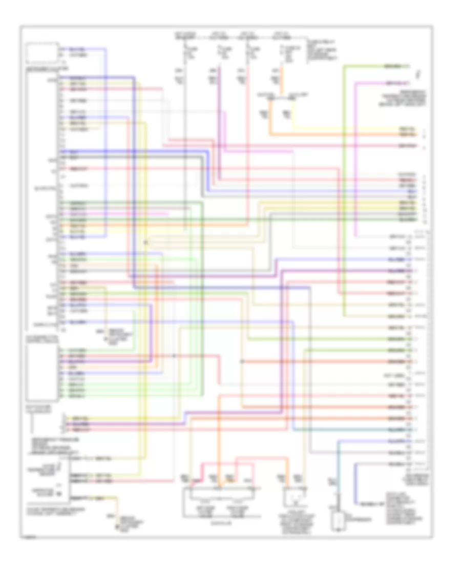
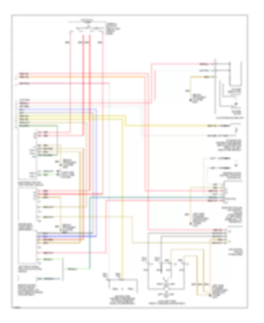
AIR CONDITIONING Automatic A/C Wiring Diagram (1 of 2) for Mercedes-Benz C280 1999 List of elements for Automatic A/C Wiring Diagram (1 of 2) for Mercedes-Benz C280 1999: 43 (behind instrument cluster) g202 (not used) 12v 15x 20b 29b 30a 38a A/c compressor A/c pushbutton control module Aspirator blower Auxiliary fan Blwr ctrl Cmpr cltch Coolant circulation pump (in lower right front of engine compartment, on frame rail) Data Data link connector (dtc readout) (partial) (in module box, on right rear corner of engine compartment) Diag Driver-side fuse & relay module box Duovalve Ed b Ed m Fr b Fuse & relay box (on left rear of engine compartment) Fuse 10a Fuse 15a Fuse 30a Fuse 38 60a (0r 30a) Hot at all times Hot in run or start In-car temperature sensor In-car temperature sensor (in dome light assembly) Instrument cluster Left-side water valve Nca Pnk Pump Refrigerant pressure sensor (on receiver-drier, behind left headlight) Refrigerant temperature sensor (on receiver-drier, behind left headlight) Right-side water valve Suction fan Sun Switchover valve block Automatic A/C Wiring Diagram (2 of 2) for Mercedes-Benz C280 1999 List of elements for Automatic A/C Wiring Diagram (2 of 2) for Mercedes-Benz C280 1999: 29 (behind instrument cluster) g202 (left side of engine compartment, near strut tower) g102 15x A/c system blower unit Air control module (if equipped) Auxiliary fans (front of engine compartment) B10 B11 B12 Blower motor Blower regulator Can h Can l Computer data lines system Driver side fuse & relay module box Electric cooling fan control module (if equipped) (in left front wheelwell, on frame rail) Electronic ignition lock control module Engine control module (me-sfi) (in module box, on right rear of engine compartment) Engine/climate control electric cooling fan Evaporator temperature sensor (above accelerator pedal, on left side of heater box) Heater core temperature sensor (in console behind radio, on heater box) Hot at all times Left auxiliary fan Left front signal pickup & activation module Nca Pwm ctrl Red Right auxiliary fan Terminal block x4 (below left side of dash)
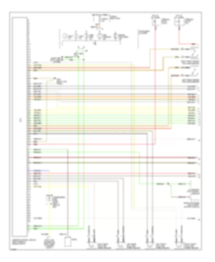
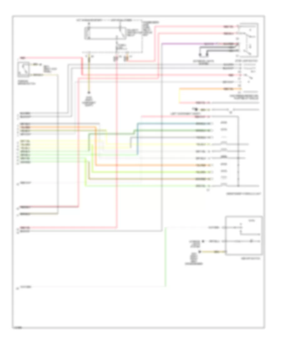
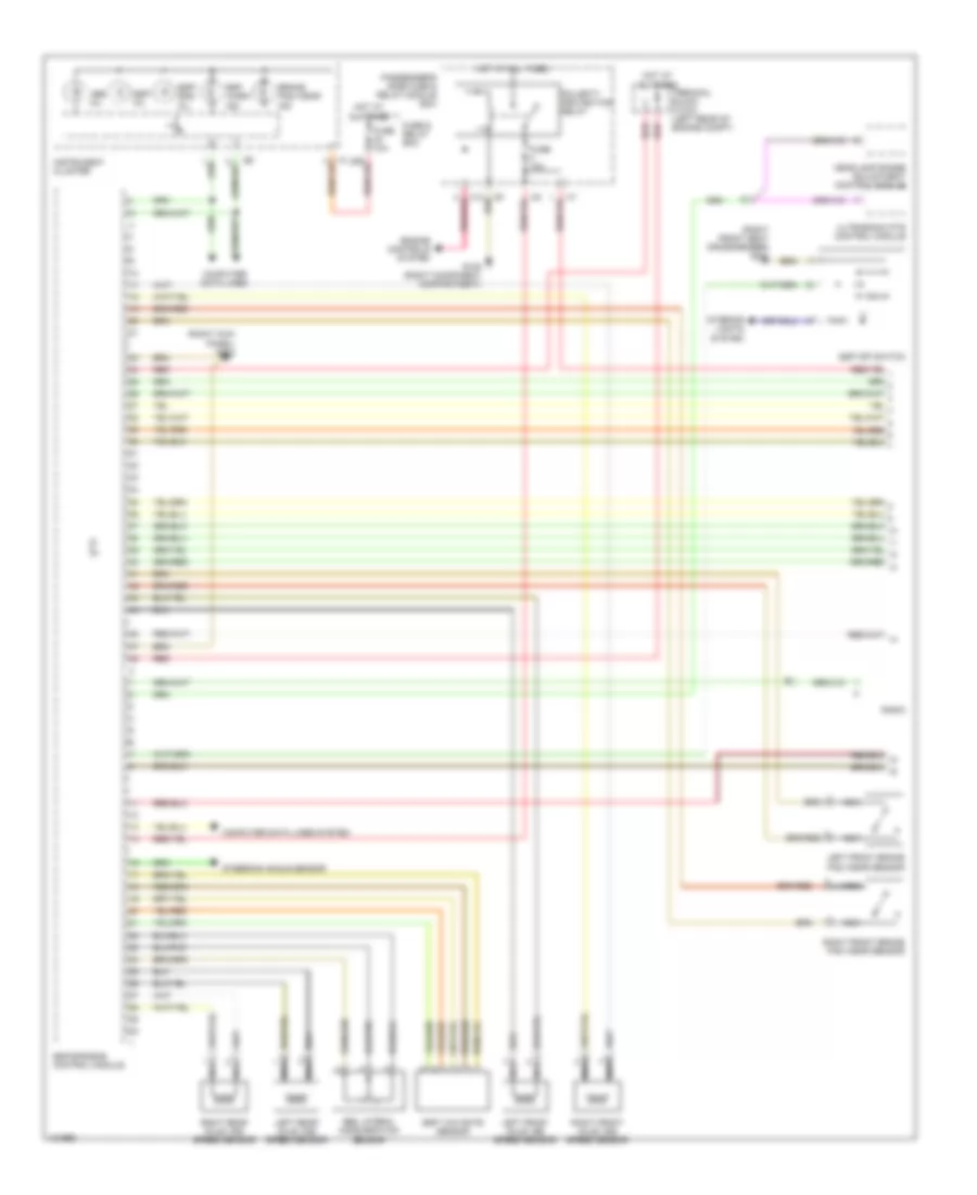
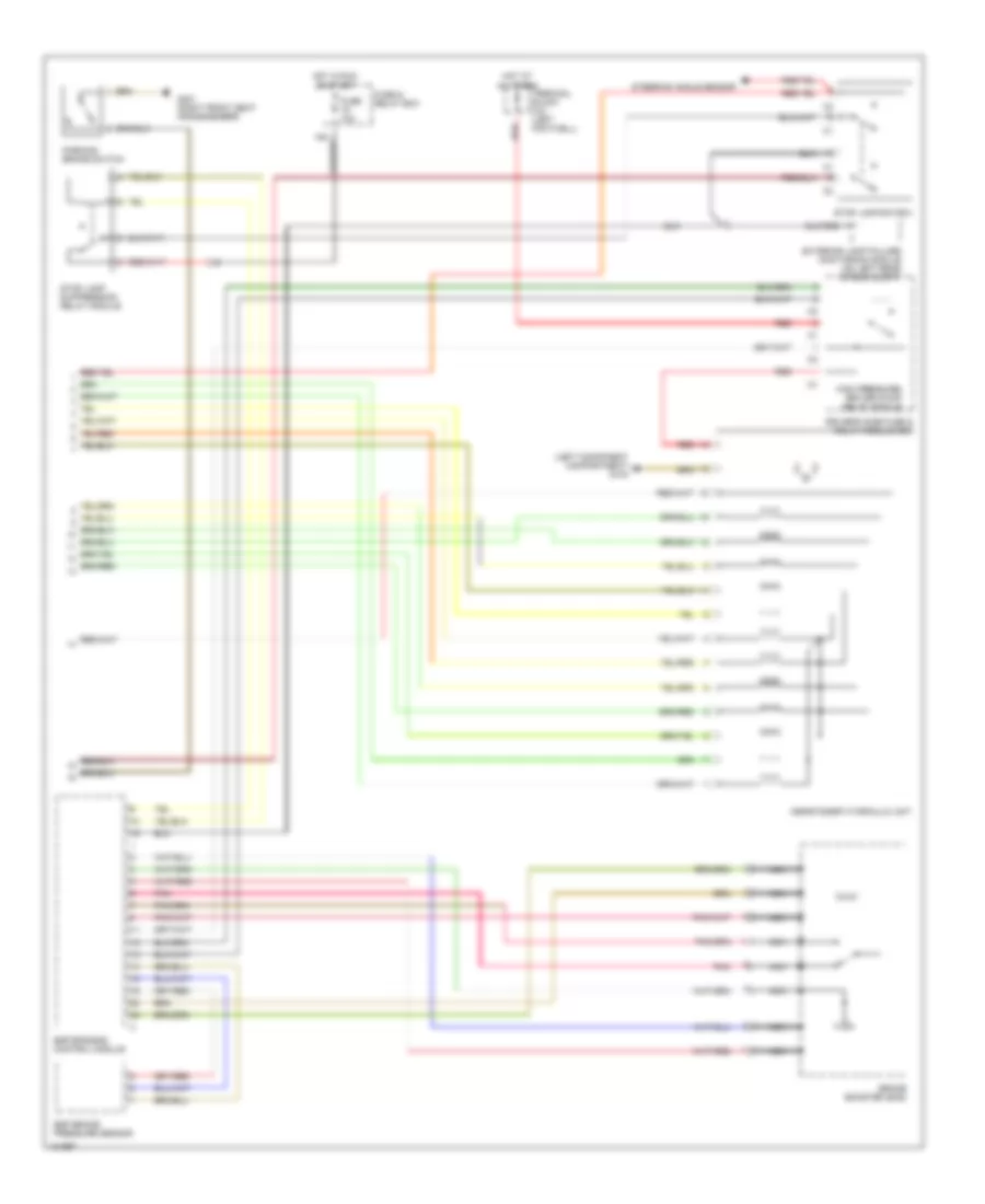
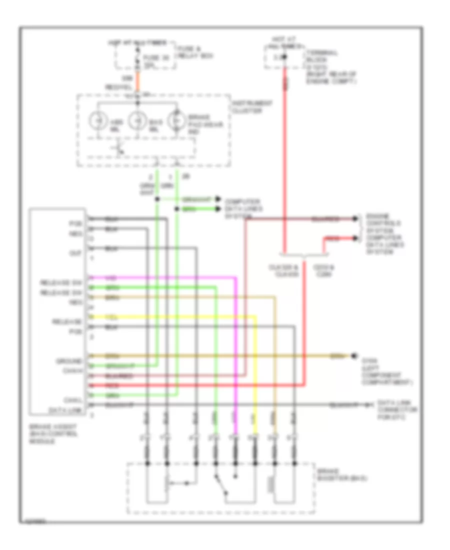
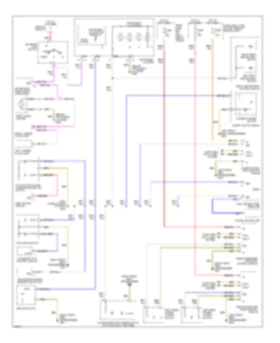
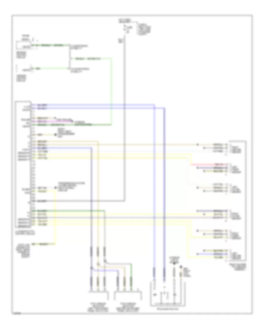
ANTI-LOCK BRAKES Anti-lock Brake Wiring Diagrams, with Acceleration Slip Regulation (1 of 2) for Mercedes-Benz C280 1999 List of elements for Anti-lock Brake Wiring Diagrams, with Acceleration Slip Regulation (1 of 2) for Mercedes-Benz C280 1999: 29 2.1 30b Abs mil Asr mil Asr warning ind Asr/ bas mil Asr/sps control module (right rear of engine compt) Brake pad wear ind Computer data lines system Data link connector (right rear of engine compt) Fuse & relay box Fuse 30 10a G203 (right kick panel) Headlamp range adjustment control module Hot at all times Instrument cluster Left front axle vss speed sensor Left front brake pad wear sensor Left rear axle vss speed sensor Nca Passenger's side fuse/ relay module box Radio Red Right front axle vss speed sensor Right front brake pad wear sensor Right rear axle vss speed sensor Terminal block (x12/3) Terminal block (x4) Ultrasonic pts control module Anti-lock Brake Wiring Diagrams, with Acceleration Slip Regulation (2 of 2) for Mercedes-Benz C280 1999 List of elements for Anti-lock Brake Wiring Diagrams, with Acceleration Slip Regulation (2 of 2) for Mercedes-Benz C280 1999: 20 (left component compt) (right front seat crossmember) Asr off switch Asr/ets/esp hydraulic unit Exterior lights system Fuse 2 10a G104 G105 (right component compt) G203 (right kick panel) G301 High pressure/return pump relay module Hot at all times Hot in run or start Interior lights system Nca Parking brake switch Passenger's side fuse/ relay module box Polarity protection relay Red Stop lamp switch Anti-lock Brake Wiring Diagrams, with Electronic Stability Program (1 of 2) for Mercedes-Benz C280 1999 List of elements for Anti-lock Brake Wiring Diagrams, with Electronic Stability Program (1 of 2) for Mercedes-Benz C280 1999: 37 (right front seat crossmember) g301 (right kick panel) g203 30b Abs lateral acceleration sensor Abs mil Brake pad wear ind Computer data lines Computer data lines system Engine controls system Esp mil Esp off switch Esp warn ind Esp yaw rate sensor Esp/ bas mil Esp/sps/bas control module Fuse & relay box Fuse 10a G105 (right component compartment) Headlamp range adjustment control module Hot at all times Instrument cluster Interior lights system Left front axle vss speed sensor Left front brake pad wear sensor Left rear axle vss speed sensor Nca Passenger's side fuse & relay module box Pnk/red Polarity protection relay Radio Red Right front axle vss speed sensor Right front brake pad wear sensor Right rear axle vss speed sensor Steering angle sensor Terminal block (x12/3) (left rear of engine compt) Ultrasonic pts control module Anti-lock Brake Wiring Diagrams, with Electronic Stability Program (2 of 2) for Mercedes-Benz C280 1999 List of elements for Anti-lock Brake Wiring Diagrams, with Electronic Stability Program (2 of 2) for Mercedes-Benz C280 1999: 21 (left component compartment) g104 Asr/ets/esp hydraulic unit Brake booster (bas) Driver's side fuse & relay module box Esp brake pressure sensor Esp/sps/bas control module Exterior lamp failure monitoring module (on left rear of eng compt) Fuse & relay box Fuse 10a G301 (right front seat crossmember) High pressure/ return pump relay module Hot at all times Hot in run or start Nca Parking brake switch Pnk Red Steering angle sensor Stop lamp suppression relay module Stop lamp switch Terminal block (x4) (left footwell) Brake Assist Wiring Diagram for Mercedes-Benz C280 1999 List of elements for Brake Assist Wiring Diagram for Mercedes-Benz C280 1999: 28 3.2 30b Abs mil Bas mil Brake assist (bas) control module Brake booster (bas) Brake pad wear ind C230 & c280 Can h Can l Clk320 & clk430 Computer data lines system Data link Data link connector for dtc Engine controls system, computer data lines system Fuse & relay box Fuse 30 10a G104 (left component compartment) Ground Hot at all times Instrument cluster Nca Out Pos Red Release Release sw Terminal block (x12/3) (right rear of engine compt)
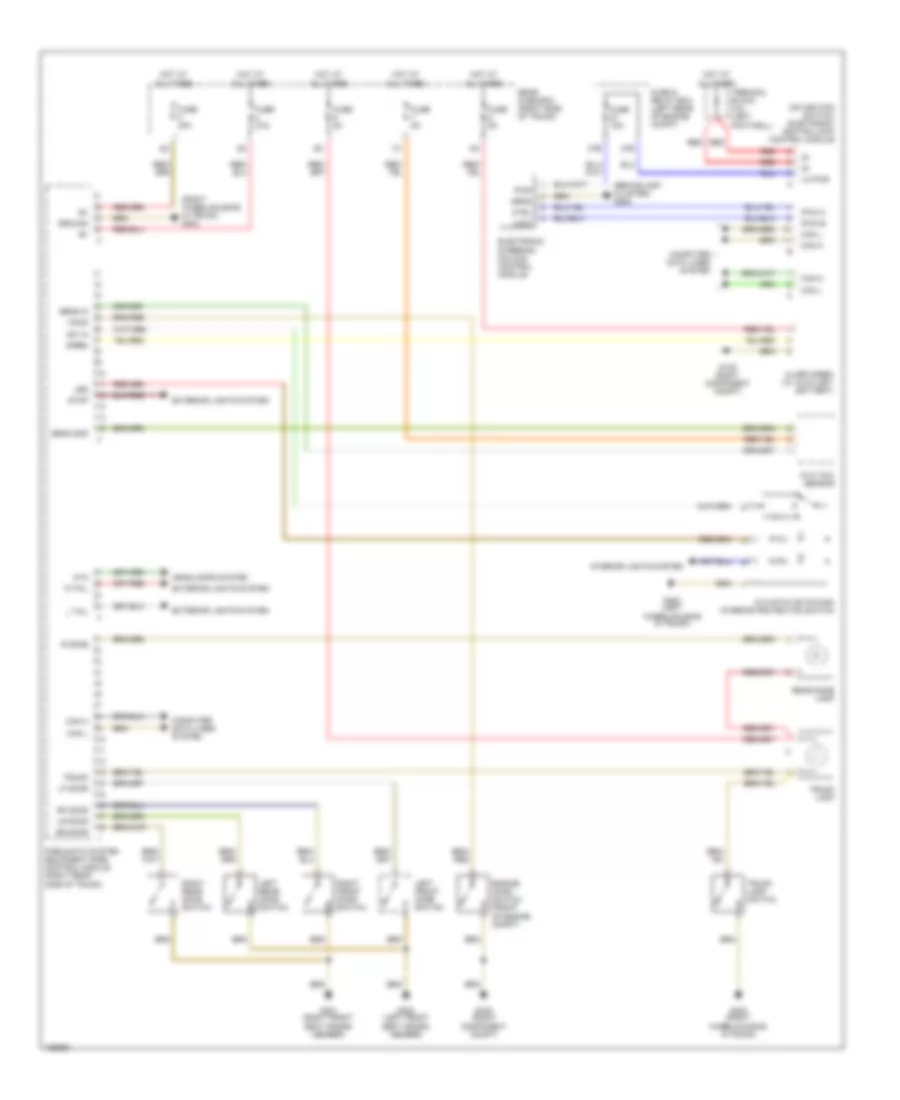
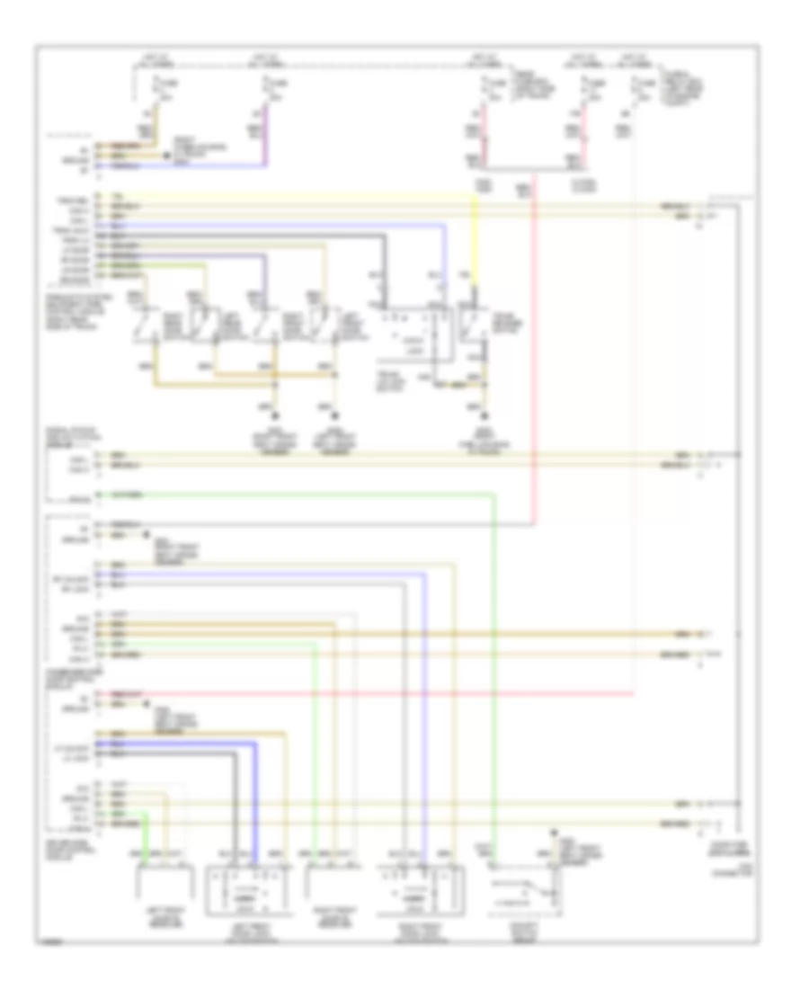
ANTI-THEFT Anti-theft Wiring Diagram for Mercedes-Benz C280 1999 List of elements for Anti-theft Wiring Diagram for Mercedes-Benz C280 1999: 61 (behind inst cluster) g202 (on ignition switch) electronic ignition lock control module (right wheelhousing, in trunk) g403 27b 27e Alarm siren (w/ auxiliary battery) Ata Ata status/towing/ interior protection switch Ata tow sensor Can h Can l Computer data lines system Ctrl Electronic steering column control module Engine hood switch (front of engine compt) Exterior lights system Fuse & relay box (left rear of engine compt) Fuse 15a Fuse 30a Fuse 40a Fuse 5a G105 (right component compt) G300 (left front seat cross- member) G301 (right front seat cross- member) G402 (left wheelhousing in trunk) G403 (right wheelhousing, in trunk) Ground Headlamps system Hood Hot at all times Interior lights system L tail Led Left front door switch Left rear door switch Lf door Lk pwr Lock Lr door Pneumatic system equipment (pse) control module (right rear side of trunk) Pwm a Pwm b Pwr R dome R tail Rear dome lamp Rear fuse box (right side of trunk) Red Rf door Right front door switch Right rear door switch Rr door Sens gnd Sens in Siren Stop Sw in Terminal block (x4) (left footwell) Trunk Trunk lamp Trunk lamp switch
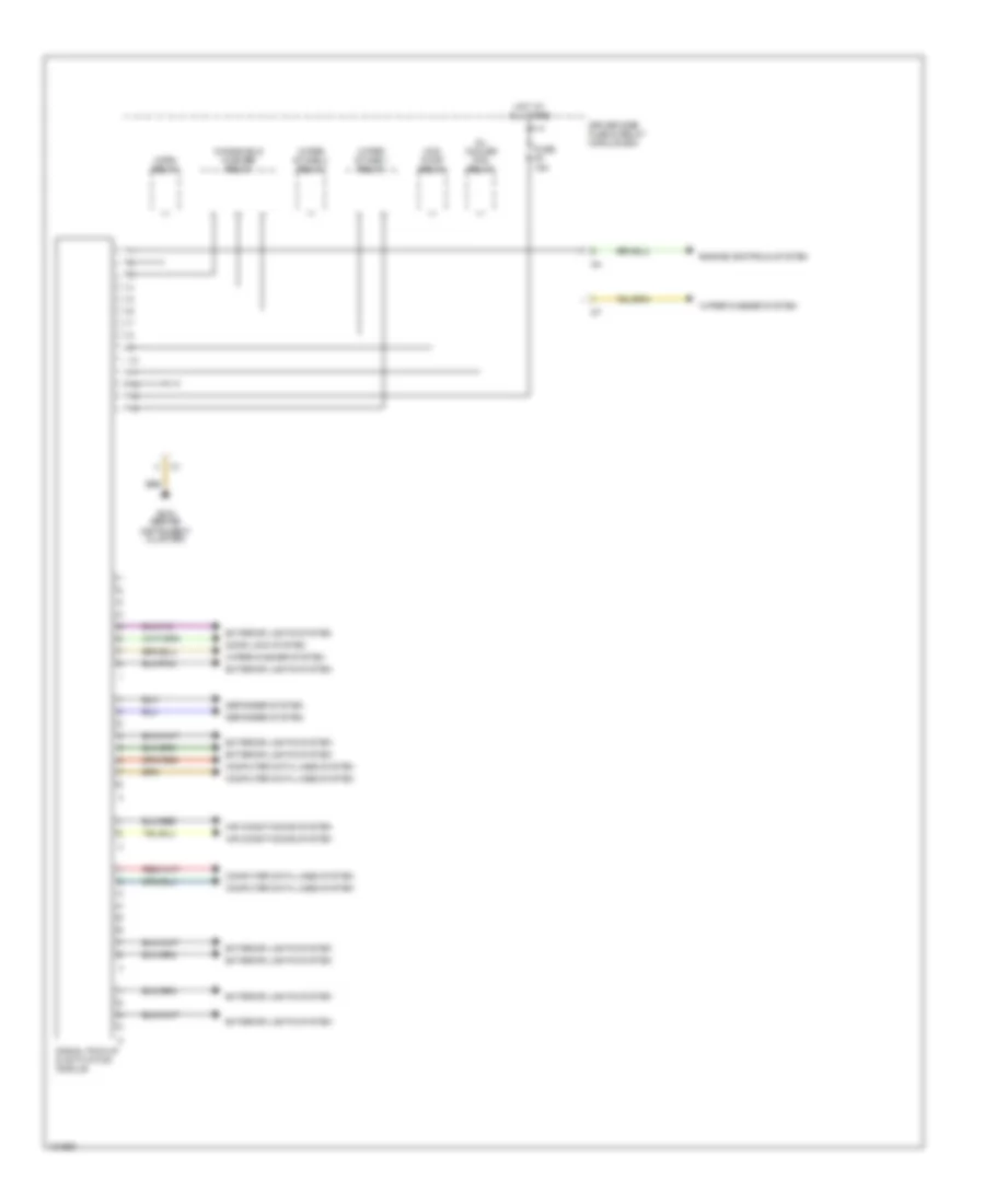
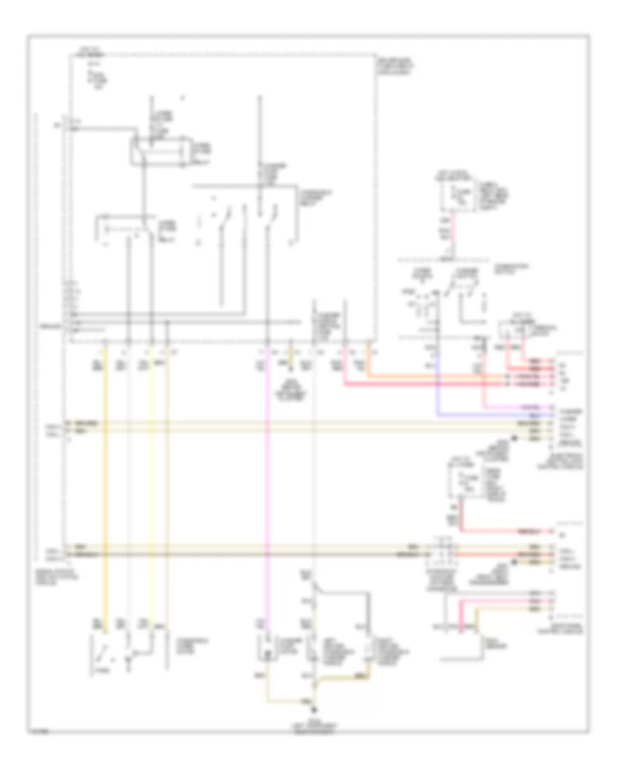
BODY COMPUTER Body Computer Wiring Diagrams for Mercedes-Benz C280 1999 List of elements for Body Computer Wiring Diagrams for Mercedes-Benz C280 1999: 18 Air conditioning system Computer data lines system Defogger system Door lock system Driver side fuse & relay module box Engine controls system Exterior lights system Fuse f5 15a G202 (behind instrument cluster) Hcs pump relay Horn relay Hot at all times Oil cooler fan relay Signal pick-up & activation module Windshield washer relay Wiper stage 1 relay Wiper stage 2 relay Wiper/washer system
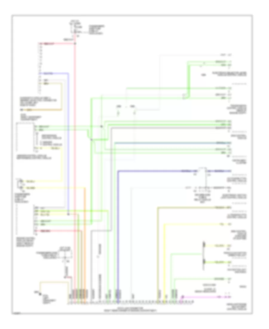
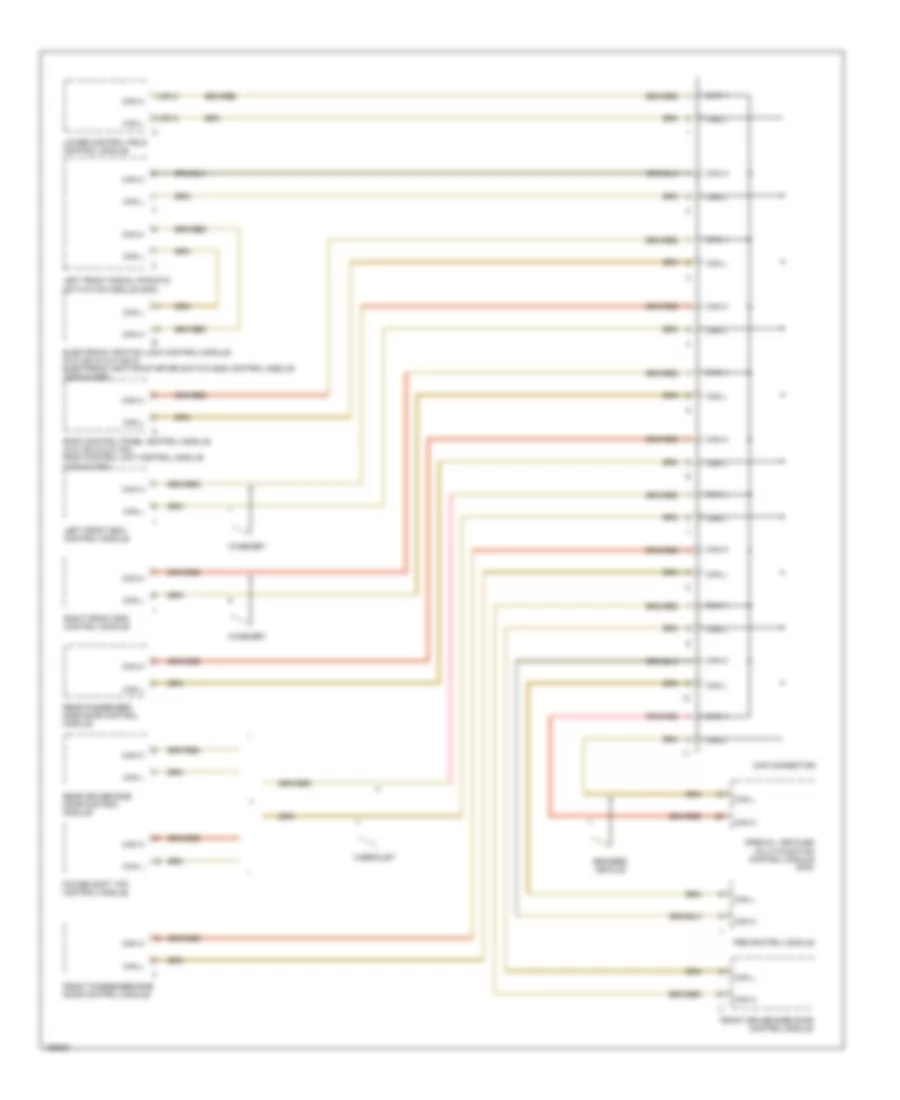
COMPUTER DATA LINES Data Link Connector Wiring Diagram for Mercedes-Benz C280 1999 List of elements for Data Link Connector Wiring Diagram for Mercedes-Benz C280 1999: 27 A/c pushbutton control module Asr/sps control module Asr/sps control module/ esp/sps/bas control module Bas control module C230 & c280 Clk320 w/ xenon headlamps Data link connector (right rear corner of engine compartment) Diagnostic module (obd ii) generic scan tool connector (on lower left side of dash) Driver's side fuse & relay module box Electronic ignition lock control module Electronic selector lever module control module Engine control module (me-sfi) (right rear of engine compt) Esp/sps/bas control module Fuse 7.5a G104 (left component compt) G105 (right component compartment) Headlamp range adjustment control module Hot at all times Hot in on or start Instrument cluster Navigation unit and radio Passenger's side fuse & relay module box Radio Radio & navigation operating unit Srs control module (forward of shifter) Transmission control module (rear of engine compt) Ultrasonic pts control module High/Low Bus Wiring Diagram for Mercedes-Benz C280 1999 List of elements for High/Low Bus Wiring Diagram for Mercedes-Benz C280 1999: 21 1 (or 4) 2 (or 3) Armored vehicle Cabriolet Can connector Can h Can l Electronic ignition lock control module (clk 320 & clk 430) & electronic ignition-starter switch (eis) control module (c230 & c280) Front driver-side door control module Front passenger-side door control module Left front esa control module Left front signal pickup & activation module (sam) Lower control field control module Power soft top control module Pse control module Rear driver-side door control module Rear passenger- side door control module Right front esa control module Roof control panel control module (clk 320 & clk 430) roof control unit control module (c230 & c280) Special vehicles multi-function control module (mfc) W/memory
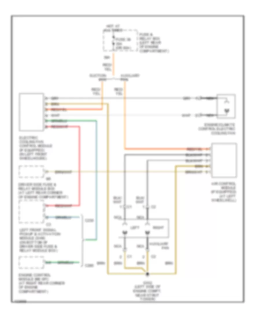
COOLING FAN Cooling Fan Wiring Diagram for Mercedes-Benz C280 1999 List of elements for Cooling Fan Wiring Diagram for Mercedes-Benz C280 1999: 18 38a Air control module (if equipped) (at left wheelwell) Auxiliary fan C230 C280 Driver side fuse & relay module box (at left rear corner of engine compartment) Electric cooling fan control module (if equipped) (in left front wheelhouse) Engine control module (me-sfi) (at right rear corner of engine compartment) Engine/climate control electric cooling fan Fuse & relay box (left rear of engine compartment) Fuse 38 30a (or 60a) G102 (left side of engine compt, near strut tower) Hot at all times Left Left front signal pickup & activation module (sam) (on bottom of driver side fuse & relay module box) Nca Right Suction fan
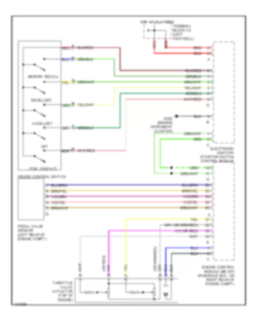
CRUISE CONTROL Cruise Control Wiring Diagram for Mercedes-Benz C280 1999 List of elements for Cruise Control Wiring Diagram for Mercedes-Benz C280 1999: 15 (or red) Accel/set Cruise control switch Ctrl contact Decel/set Electronic ignition- starter switch control module Engine control module (me-sfi) (in module box, on right rear of engine compt) G202 (behind intrument cluster) Hot at all times Memory recall Off Pedal value sensor (left rear of engine compt) Red Terminal block x4 (left footwell) Throttle valve actuator (top of engine)
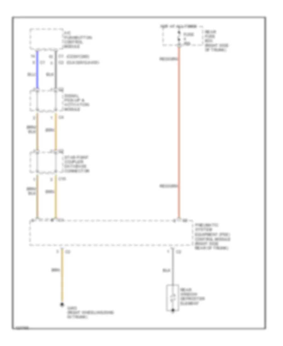
DEFOGGERS Defogger Wiring Diagram for Mercedes-Benz C280 1999 List of elements for Defogger Wiring Diagram for Mercedes-Benz C280 1999: 13 (c230/c280) (clk320/clk430) A/c pushbutton control module C10 Equipment (pse) control module (right side rear of trunk) Fuse 40a G403 (right wheelhousing in trunk) Hot at all times Pneumatic system Rear window defroster element Rear fuse box (right side of trunk) Signal pick-up & activation module Star point coupler database connector
ENGINE PERFORMANCE
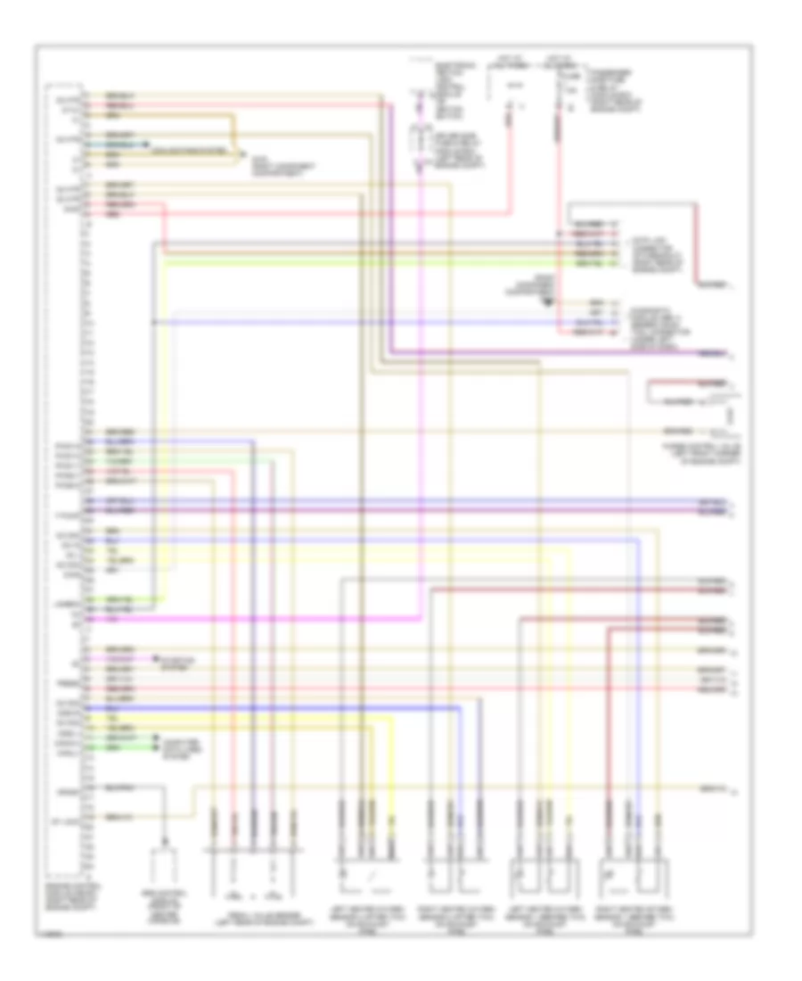
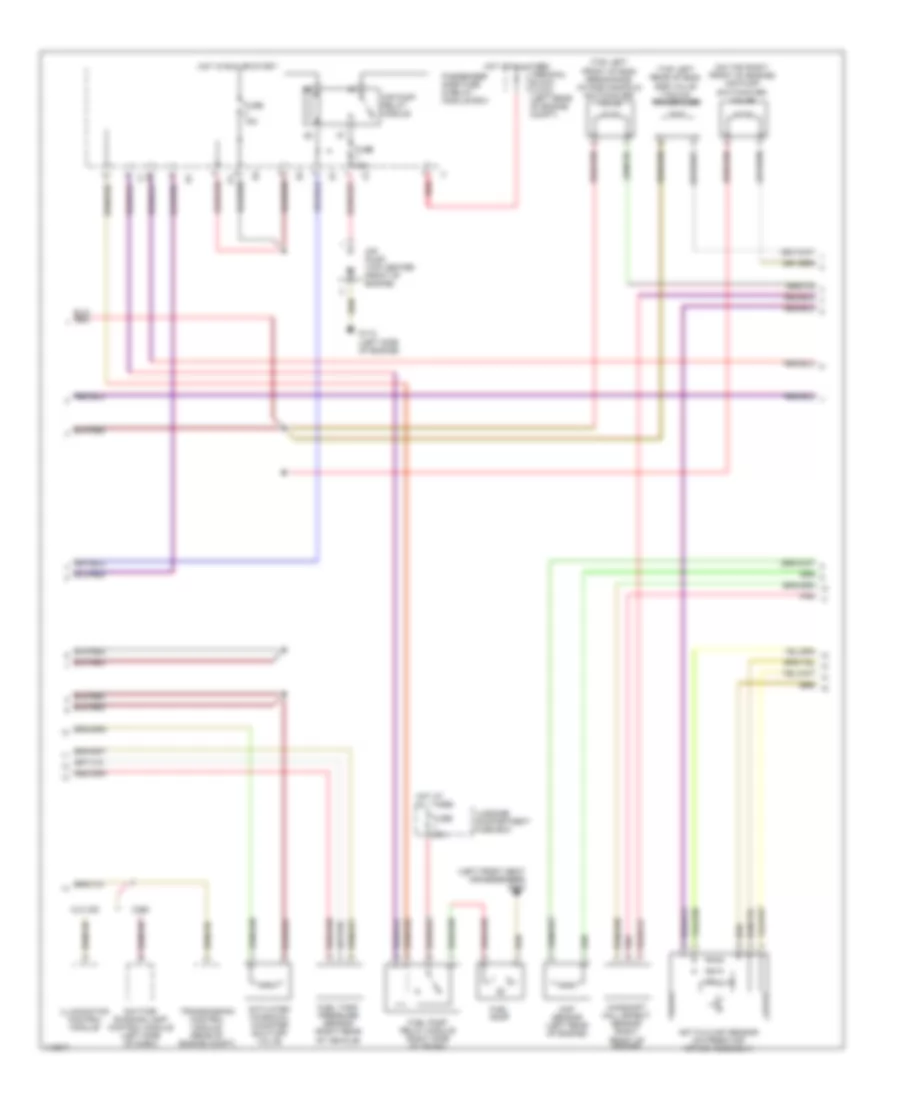
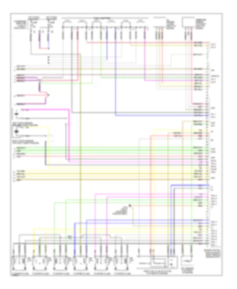
2.8L 2.8L, Engine Performance Wiring Diagrams (1 of 3) for Mercedes-Benz C280 1999 List of elements for 2.8L, Engine Performance Wiring Diagrams (1 of 3) for Mercedes-Benz C280 1999: 41 (right component compartment) g103 87 m1 Can(h)+ Can(l)- Computer data lines system Cooling fans system Crash Data link connector (dtc readout) (right rear of engine compt) Diag Diagnostic module (obd ii) generic scan tool connector (under left side of dash) Driver side fuse & relay module box (left rear of engine compt) Electronic ignition lock control module b (on ignition switch) Engine control module (me-sfi) (right rear of engine compt) F pump Fuse 7.5a G103 (right component compartment) Hot at all times Lambda Left heated oxygen sensor 1 (before twc) (on exhaust pipe) Left heated oxygen sensor 2 (after twc) (on exhaust pipe) O2 1 O2 com O2 htr O21 r O2s2 l O2s2 r Passenger side fuse & relay module box (right rear of engine compt) Pedal value sensor (left rear of engine compt) Press Purge control valve (left front corner of engine compt) Pwg0-2 Pwg1-0 Pwg1-1 Pwg1-2 Pwg2-1 Red Right heated oxygen sensor 1 (before twc) (on exhaust pipe) Right heated oxygen sensor 2 (after twc) (on exhaust pipe) Srs control module (front of center console) St lock Starting system 2.8L, Engine Performance Wiring Diagrams (2 of 3) for Mercedes-Benz C280 1999 List of elements for 2.8L, Engine Performance Wiring Diagrams (2 of 3) for Mercedes-Benz C280 1999: 29 (left front seat crossmember) g300 (on top right front of engine) air pump switchover valve (top left front of eng) resonance intake manifold switchover valve (top left rear of eng) egr valve vacuum transducer Activated charcoal canister shut-off valve Air pump (top center front of engine) Air pump relay module C280 Camshaft hall effect sensor (right front of engine) Ckp sensor (left rear of engine) Clk 320 Daytime running lamp control module (left side of dash) Fuel pump Fuel pump relay module (right side of trunk) Fuel tank pressure sensor (right rear of vehicle) Fuse 15a Fuse 25a Fuse 40a G112 (left side of engine) Hot at all times Hot film maf sensor (on fresh air intake assembly) Hot in run or start Illumination control module Luggage compartment fuse box Passenger side fuse & relay module box Pnk Red Terminal block (x12/3) (left rear of engine compt) Transmission control module (rear of engine compt) 2.8L, Engine Performance Wiring Diagrams (3 of 3) for Mercedes-Benz C280 1999 List of elements for 2.8L, Engine Performance Wiring Diagrams (3 of 3) for Mercedes-Benz C280 1999: 43 Air Ckp+ Ckp- Cmp Coil 1 Coil 2 Coil 3 Coil 4 Coil 5 Coil 6 Com Ect sensor (top front of engine) Engine control module (me-sfi) (right rear of engine compt) Etc Fuel injectors Fuse 15a Fuse 20a G103 (right component compartment) Hfm+ Hfm- Hot in run or start Ign coil Inj 1 Inj 2 Inj 3 Inj 4 Inj 5 Inj 6 Ks (l) Ks (r) Left knock sensor (top left side of engine) Manifld Map Nca Oil sensor (lower front of engine) Passenger side fuse & relay module box Pnk Pressure sensor (top right front of engine) Red Right knock sensor (top right side of engine) Shld Throttle valve actuator (top rear of engine) To spark plugs
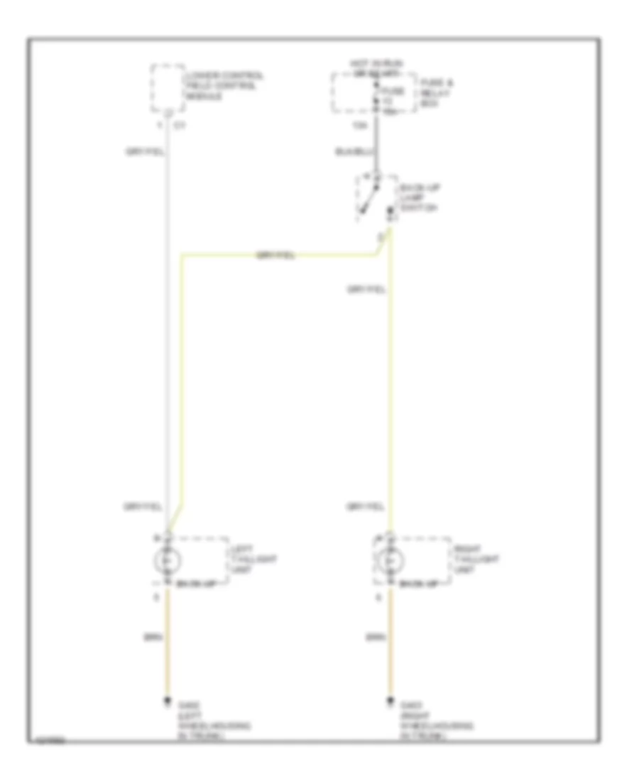
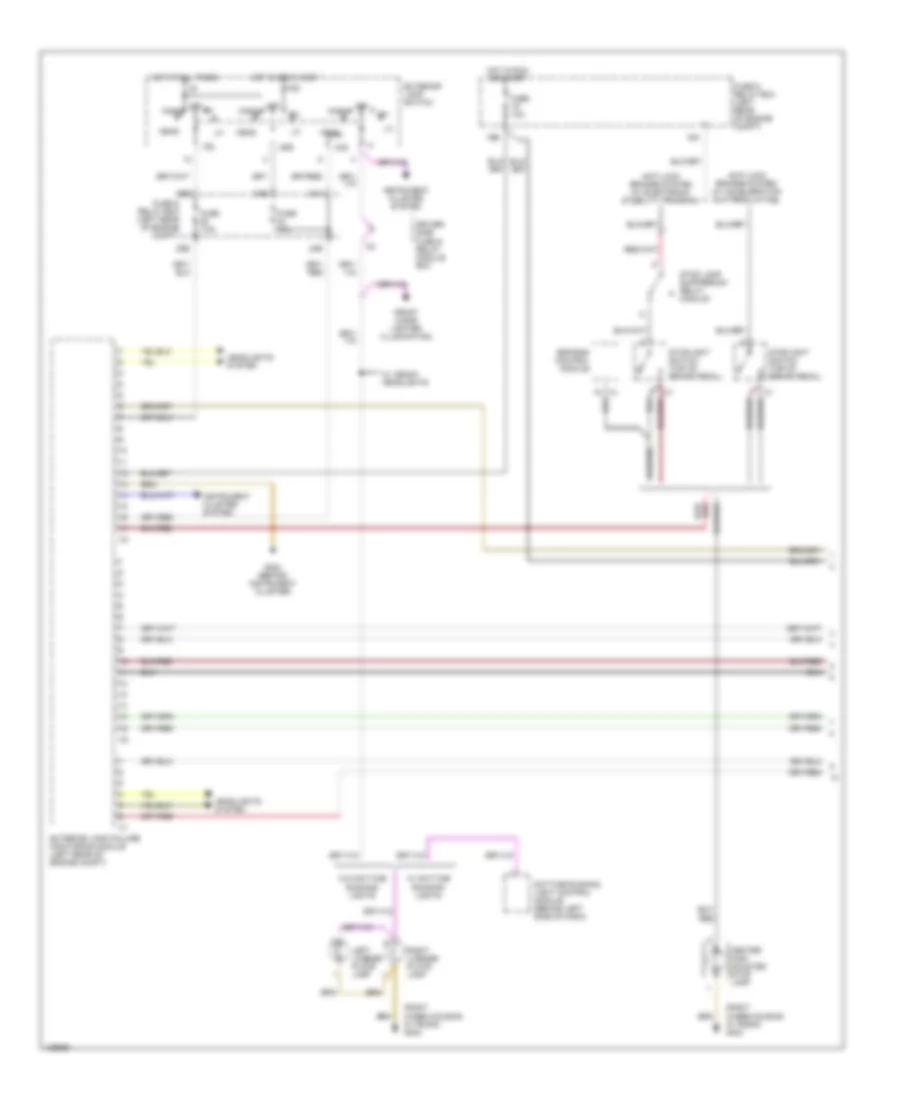
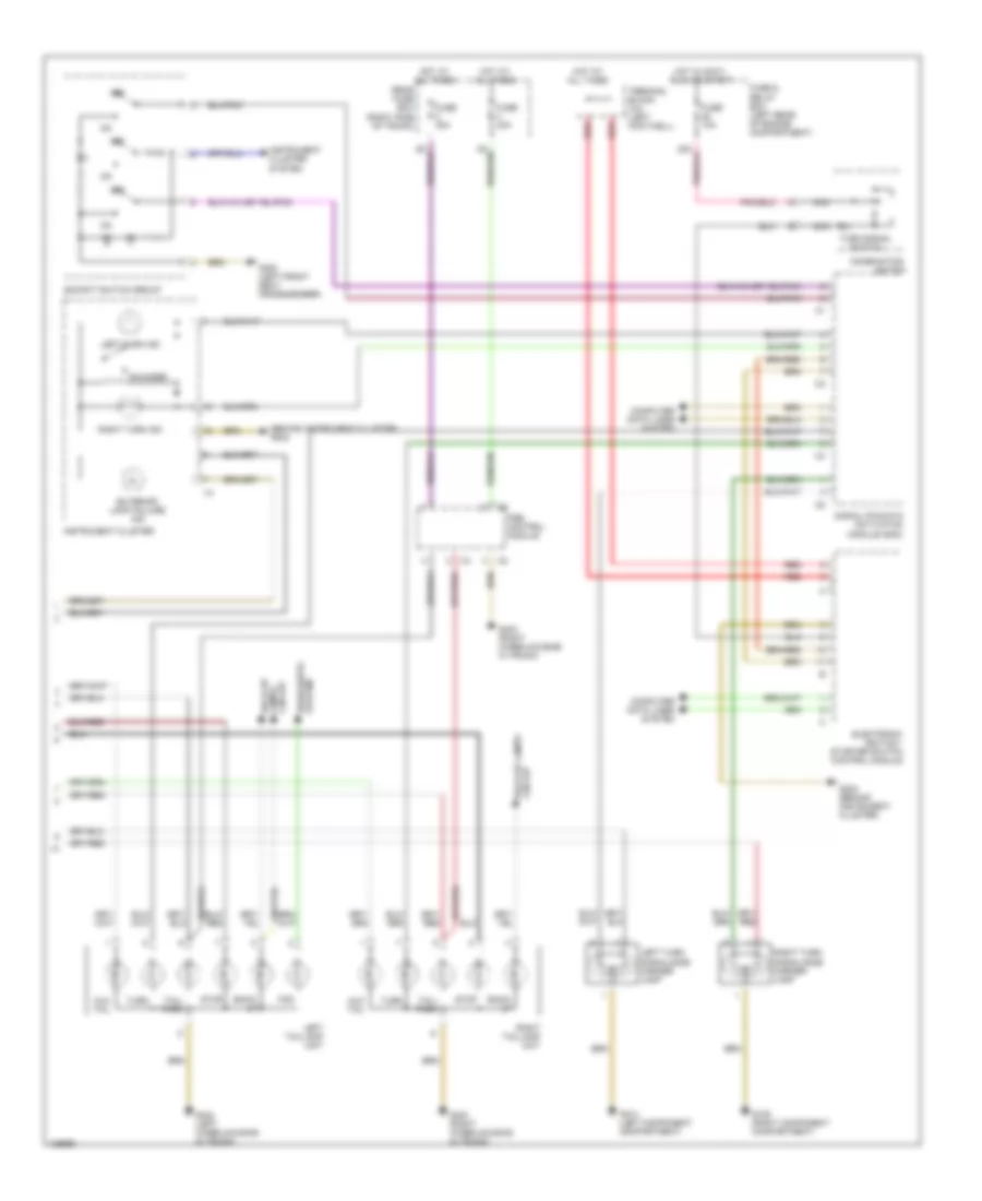
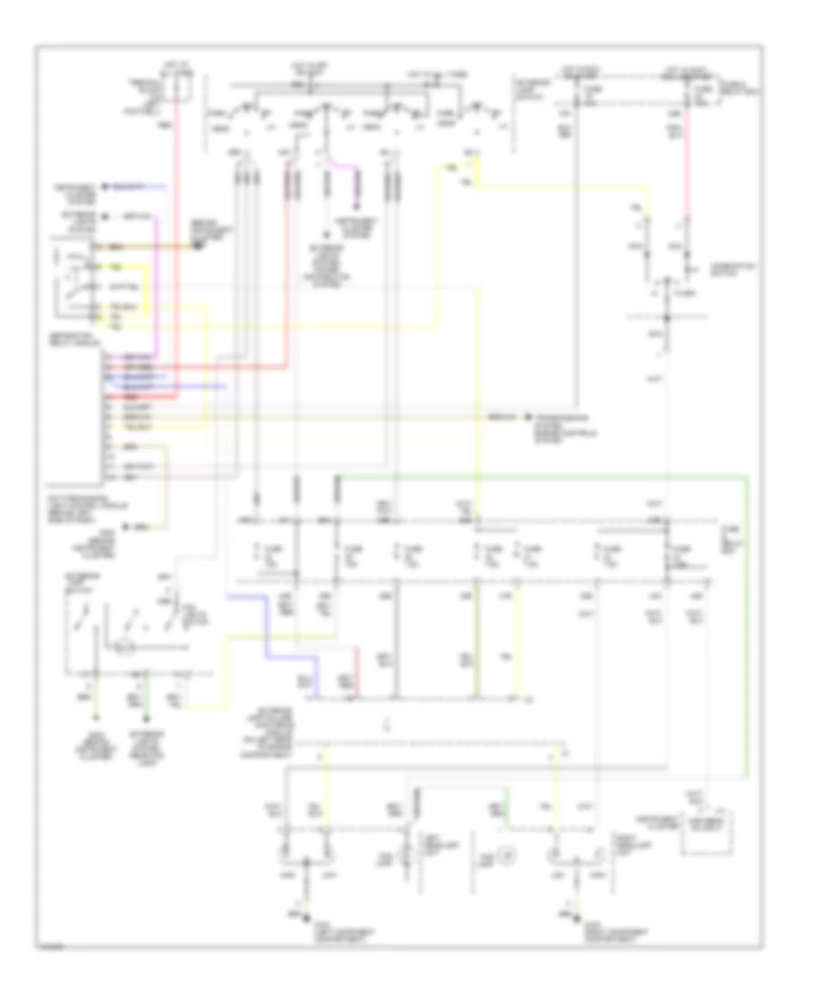
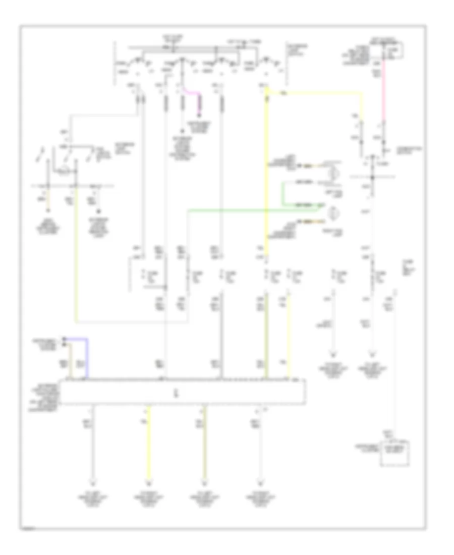
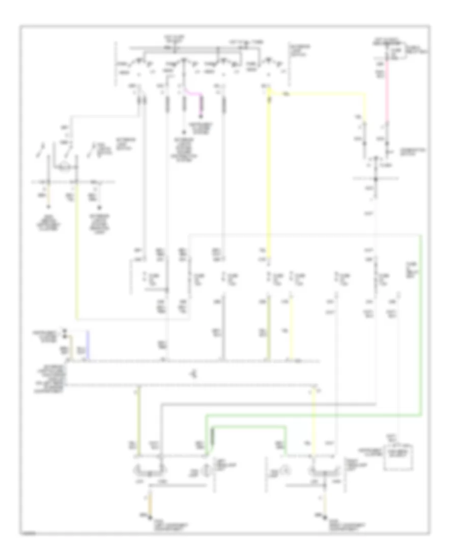
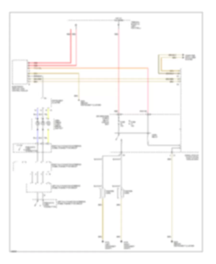
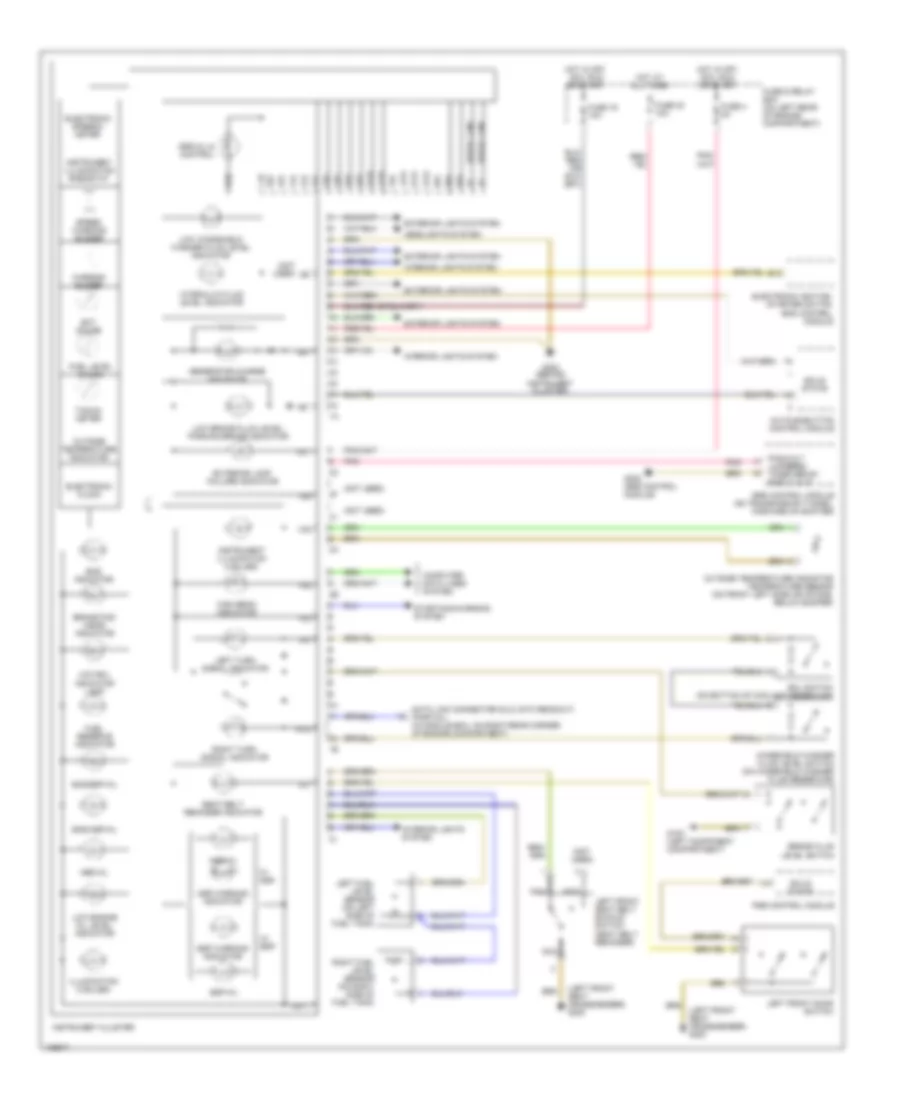
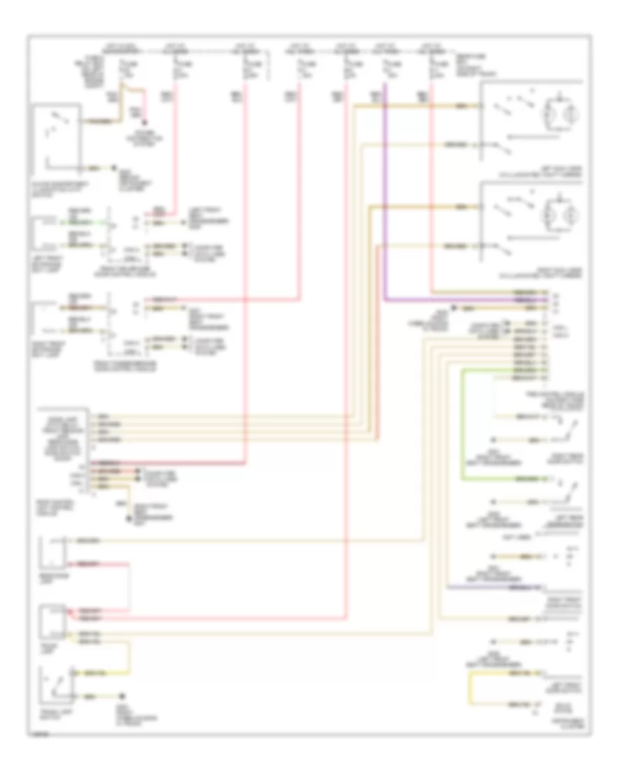
EXTERIOR LIGHTS Back-up Lamps Wiring Diagram for Mercedes-Benz C280 1999 List of elements for Back-up Lamps Wiring Diagram for Mercedes-Benz C280 1999: 11 13a Back-up Back-up lamp switch Fuse & relay box Fuse 15a G402 (left wheelhousing in trunk) G403 (right wheelhousing in trunk) Hot in run or start Left taillight unit Lower control field control module Right taillight unit Exterior Light Wiring Diagram (1 of 2) for Mercedes-Benz C280 1999 List of elements for Exterior Light Wiring Diagram (1 of 2) for Mercedes-Benz C280 1999: 42 (right wheelhousing in trunk) g403 19a 19b 24b 24c 24e 25b 25e 58l 58r Anti-lock brakes system (w/ acceleration slip regulation) Anti-lock brakes system (w/ electronic stability program) Center high mounted stop lamp Daytime running light control module (behind left side of dash) Driver- side fuse & relay module box Esp/bas control module Exterior lamp failure monitoring module (left rear of engine compt) Exterior lamp switch Front cigar lighter (illumination) Fuse & relay box (left rear of engine compt) Fuse 10a Fuse 15a Fuse 7.5a G202 (behind instrument cluster) Head Headlights system Hot at all times Hot in off & accy Hot in run or start Instrument cluster system K30 Left license plate lamp Off P30 Park Red Right license plate lamp Stop lamp suppresion relay module Stoplight switch (top of brake pedal) W/ daytime running lights W/ xenon headlights W/o daytime running lights Exterior Light Wiring Diagram (2 of 2) for Mercedes-Benz C280 1999 List of elements for Exterior Light Wiring Diagram (2 of 2) for Mercedes-Benz C280 1999: 46 (behind instrument cluster) g202 Aux tail Back- up Back-up lamps circuit Circuit back-up lamps Cockpit switch group Combination Computer data lines system Electronic ignition - starter switch control module Exterior lamp failure ind Fog Fuse & relay box (left rear of engine compartment) Fuse 10a Fuse 30a Fuse 40a G104 (left component compartment) G105 (right component compartment) G202 (behind instrument cluster) G300 (left front seat crossmember) G402 (left wheelhousing in trunk) G403 (right wheelhousing in trunk) Headlights system Hot at all times Hot in accy, run, or start Instrument cluster Instrument cluster system Left taillamp unit Left turn ind Left turn signal/side marker lamp Nca Off Pse control module R/l Rear fuse box (right side of trunk) Red Right taillamp unit Right turn ind Right turn signal/side marker lamp Signal pickup & activation module (sam) Sounder Stop Switch Tail/ park Terminal block (x4) (left footwell) Turn Turn signal switch
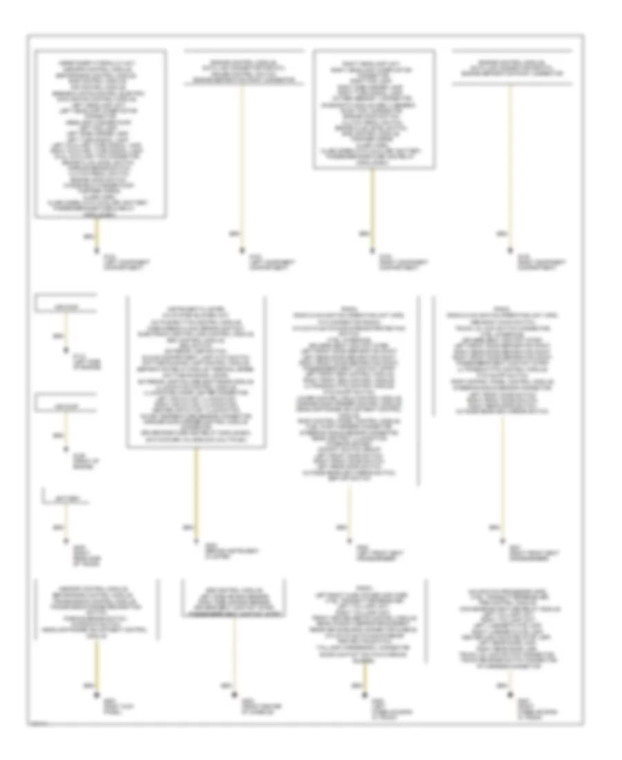
GROUND DISTRIBUTION Ground Distribution Wiring Diagram for Mercedes-Benz C280 1999 List of elements for Ground Distribution Wiring Diagram for Mercedes-Benz C280 1999: 92 (door contact switch/warning A/c pushbutton control module, A/c system blower unit, Air pump Alarm horn, Alarm siren with auxiliary battery, Asr snow chain switch, Asr/ets/esp hydraulic unit, Asr/sps control module, Ata connector (radio), Ata status/towing/interior Ata status/towing/interior protection switch, ctel interface, driver's seat contact strip, left front door separation point, left rear door separation point, right front door separation point, passenger's seat contact strip, left front esa control module, right front esa control module, ultrasonic pts control module, Bas control module, Bas control module, air control module, Battery Brake fluid level switch, Buzzer), Center high mounted stop lamp, Connector, Convenience feature relay module, Cooling fan control module, Ctel transmitter-receiver, Daytime running lamps), exterior lamp failure monitoring module, illumination control module, illuminated cigar lighter connector, left air outlet illumination, right air outlet illumination, center air outlet illumination, in-car temperature sensor connector, garage door opener control module connector, driver-side fuse and relay module box, Diagnostic module (obd ii) generic Dual auxiliary fan connector, Engine control module, data link connector for dtc, cruise control switch, engine separation point connector Engine control module, data link connector for dtc, engine separation point connector Engine hood switch, clutch pedal switch, Engine/climate control electric Esp/sps/bas control module, Esp/sps/bas control module, transmission control module, Fanfare horns, Fp harness connector Front heated seats control module, G104 (left component compartment) G105 (right component compartment) G112 (left side of engine) G125 (front of engine) G202 (behind instrument cluster) G203 (right kick panel) G300 (left front seat crossmember) G301 (right front seat crossmember) G302 (front center of console) G402 (left wheelhousing in trunk) G403 (right wheelhousing in trunk) G405 (right rear side of trunk) Headlamp range adjustment control Headlamp washer pump, Horn/airbag clock spring contact, electronic ignition lock control module, esc control module, esc switch, exterior lamp switch, glove compartment lamp with switch, daytime running lamp control module, Instrument cluster, Kickdown switch, Left auxiliary turn signal lamp, right auxiliary turn signal lamp, Left fog lamp, Left front door switch, right front door switch, right rear door switch, outside rearview mirror switch, Left headlamp unit, Left headlamp wiper motor Left license plate lamp, right license plate lamp, Left rear dome lamp, right rear dome lamp, Left side marker lamp, left turn signal lamp, Left taillamp unit, right taillamp unit, Left/right audio power amplifier, Module Module box Navigation processor (aps), ctel transmitter-receiver, Oxygen sensor 1 connector, Parking brake switch, Parking brake switch, clutch pedal switch, engine hood switch, Passenger-side fuse & relay Passenger-side fuse and relay Protection switch, Pse control module, Pts on/off switch, Pts on/off switch, lower control field control module, garage door opener control module, headlamp range adjustment control module, roof control panel control module, fuel pump harness connector, steering angle sensor connector, rear ashtray illumination, interior socket, cockpit switch group, left front door switch, right front door switch, left rear door switch, outside rearview mirror switch, esp off switch Radio & navigation operating unit (aps), Radio, Rear window defroster element, Receiver shielding connector sleeve, Right fog lamp, Right headlamp unit, Right headlamp wiper motor Right side marker lamp, right turn signal lamp, Roof control panel control module, steering angle sensor connector, Scan tool connector, Separation relay module (terminal 56/56b, Srs control module, left side air bag sensor, right side air bag sensor, driver's seat contact strip, passenger's seat contact strip Switch, Switchover valve block (multiplex) Taillamp harness/rcl connector Transmission range recognition Trunk lid lock switch connector, ctel interface, driver's seat contact strip, left front door separation point, right rear door separation point, right front door separation point, passenger's seat contact strip, ultrasonic pts control module, Trunk lid lock switch connector, trunk release switch connector, Windshield washer pump,
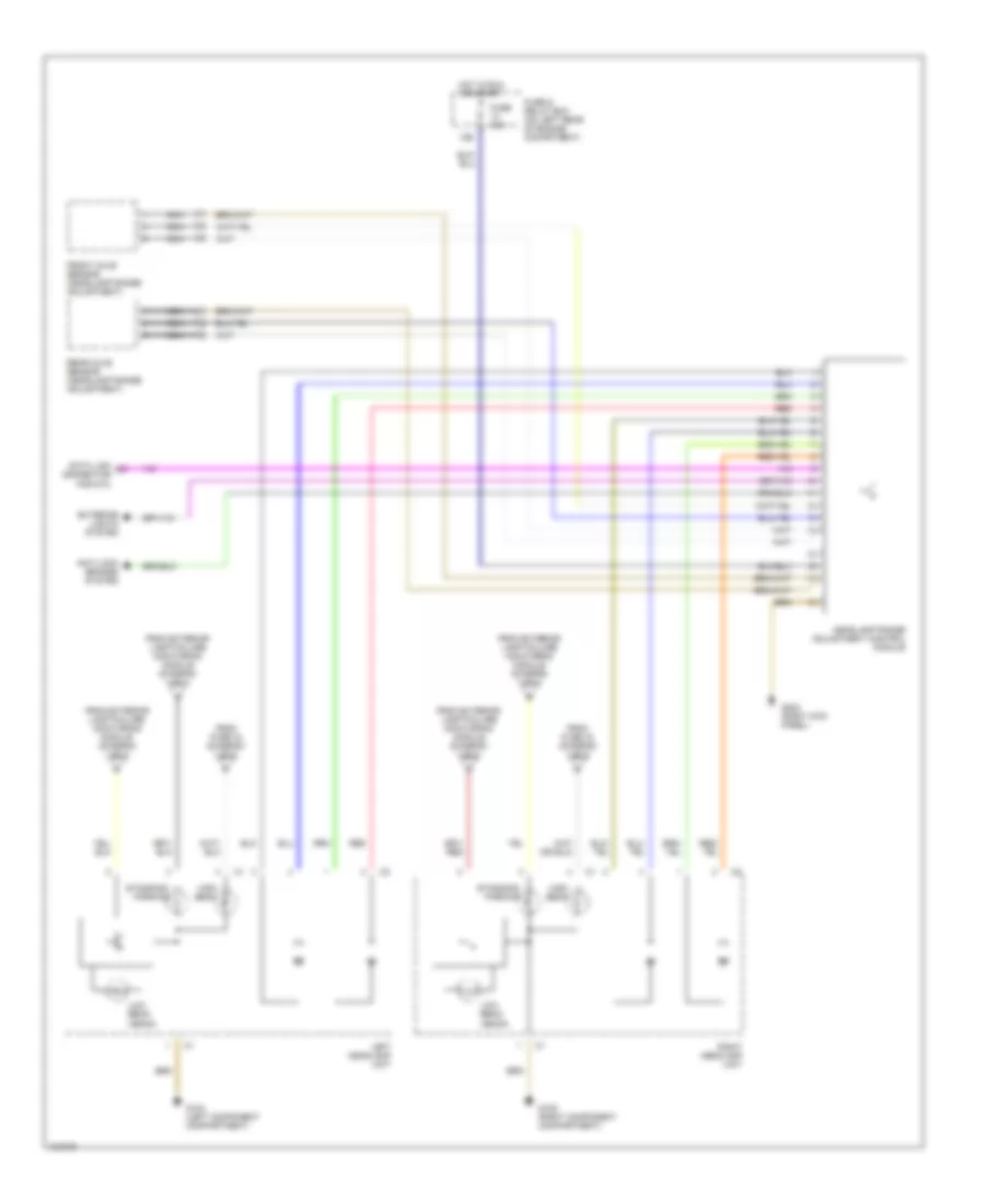
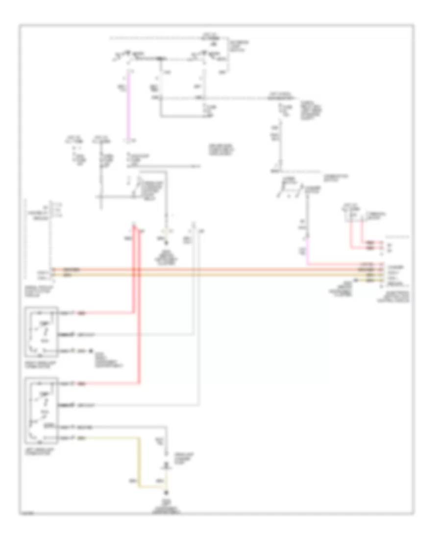
HEADLIGHTS Headlight Wiring Diagram, with DRL for Mercedes-Benz C280 1999 List of elements for Headlight Wiring Diagram, with DRL for Mercedes-Benz C280 1999: 63 (behind instrument cluster) g202 1/a 19a 22b 24b 24c 24e 25b 25e 31b 32b 32e 33b 34a 34b 34e 35a 35e 58l 58r Combination switch Daytime running light control module (behind left side of dash) Exterior lamp Exterior lamp failure Exterior lamp switch Exterior lights system Exterior lights system (rear fog lamp) Exterior lights system, power distribution system Flash Fog lamp Fog lights switch Fuse & relay box Fuse 10a Fuse 15a Fuse 7.5a G104 (left component compartment) G105 (right component compartment) G202 (behind instrument cluster) Head High High beam on input Hot at all times Hot in accy, run, or start Hot in off or accy Hot in run or start Instrument cluster Instrument cluster system K30 Left headlamp unit Low Module (on left rear of engine compartment) Monitoring Nca Nse Off P30 Park Red Right headlamp unit Separation relay module Switch Terminal block (x4) (left footwell) Transmissions system, engine controls system Headlight Wiring Diagram, with Xenon Lamps (1 of 2) for Mercedes-Benz C280 1999 List of elements for Headlight Wiring Diagram, with Xenon Lamps (1 of 2) for Mercedes-Benz C280 1999: 52 (left component compartment) g104 1/a 22b 24b 24c 24e 25b 25e 31b 31e 32b 33a 33e 34a 34b 35a 35e 58l 58r Combination switch Exterior lamp failure Exterior lamp switch Exterior lights system (rear fog lamp) Exterior lights system, power distribution system Flash Fog lights switch Fuse & relay box Fuse & relay box (on left rear of engine comartment) Fuse 10a Fuse 15a Fuse 7.5a G105 (right component compartment) G202 (behind instrument cluster) Head High beam on input Hot at all times Hot in accy, run, or start Hot in off or accy Instrument cluster Instrument cluster system K30 Left fog lamp Module (on left rear of engine compartment) Monitoring Nca Nse Off P30 Park Right fog lamp To left headlamp unit (diagram 2 0f 2) To right headlamp unit (diagram 2 0f 2) Headlight Wiring Diagram, with Xenon Lamps (2 of 2) for Mercedes-Benz C280 1999 List of elements for Headlight Wiring Diagram, with Xenon Lamps (2 of 2) for Mercedes-Benz C280 1999: 23 13b Anti-lock brakes system Data link connector for dtc Exterior lights system From exterior lamp failure monitoring module (diagram 1 0f 2) From fuse 33 (diagram 1 0f 2) From fuse 34 (diagram 1 0f 2) Front axle sensor (headlamp range adjustment) Fuse & relay box (on left rear of engine comartment) Fuse 15a G104 (left component compartment) G105 (right component compartment) G203 (right kick panel) Headlamp range adjustment control module High beam Hot in run or start Left headlamp unit Low beam xenon Nca Rear axle sensor (headlamp range adjustment) Red Right headlamp unit Standing/ parking Headlight Wiring Diagram, without Xenon Lamps for Mercedes-Benz C280 1999 List of elements for Headlight Wiring Diagram, without Xenon Lamps for Mercedes-Benz C280 1999: 52 1/a 22b 24b 24c 24e 25b 25e 31b 31e 32b 33a 33e 34a 34b 35a 35e 58l 58r Combination switch Exterior lamp failure Exterior lamp switch Exterior lights system (rear fog lamp) Exterior lights system, power distribution system Flash Fog lamp Fog lights switch Fuse & relay box Fuse 10a Fuse 15a Fuse 7.5a G104 (left component compartment) G105 (right component compartment) G202 (behind instrument cluster) Head High High beam on input Hot at all times Hot in accy, run, or start Hot in off or accy Instrument cluster Instrument cluster system K30 Left headlamp unit Low Module (on left rear of engine compartment) Monitoring Nca Nse Off P30 Park Right headlamp unit
HORN Horn Wiring Diagram for Mercedes-Benz C280 1999 List of elements for Horn Wiring Diagram for Mercedes-Benz C280 1999: 19 Computer data lines system Driver's side fuse & relay module box Electronic ignition lock control module Fanfare horn Fuse 10a Fuse 15a G104 (left component compt) G105 (right component compt) G202 (behind instrument cluster) Horn relay Horn/ airbag clock spring contact Hot at all times Instrument cluster Left multi-function steering wheel pushbutton group Pneumatic horn pushbutton Red Right multi-function steering wheel pushbutton group Signal pick-up & activation module (sam) Terminal block x4 (left footwell)
INSTRUMENT CLUSTER
INTERIOR LIGHTS Courtesy Lamps Wiring Diagram for Mercedes-Benz C280 1999 List of elements for Courtesy Lamps Wiring Diagram for Mercedes-Benz C280 1999: 39 (left front seat crossmember) g300 (not used) (right front seat crossmember) g301 Can h Can l Computer data lines system Dome lamp with delay/ front reading lamp, rear dome lamp switch, door switch on/off Front driver side door control module Front passenger side door control module Fuse & relay box (on left rear of engine compt) Fuse 15a Fuse 25a Fuse 30a Fuse 40a Fuse 5a G202 (behind instrument cluster) G300 (left front seat crossmember) G301 (right front seat crossmember) G403 (right wheelhousing in trunk) Glove compartment illumination with switch Hot at all times Hot in acc, run or start Instrument cluster Left front door switch Left front entrance/ exit lamp Left rear door switch Left sun visor (w/illuminated vanity mirror) Power distribution system Pse control module (on right side rear of trunk) Rear dome lamp Rear fuse box (on right side of trunk) Right front door switch Right front entrance/ exit lamp Right rear door switch Right sun visor (w/illuminated vanity mirror) Roof control unit control module Solid state Trunk lamp Trunk lamp switch Instrument Illumination Wiring Diagram for Mercedes-Benz C280 1999 List of elements for Instrument Illumination Wiring Diagram for Mercedes-Benz C280 1999: 53 (behind instrument cluster) g202 (left front seat crossmember) g300 (left wheelhousing in trunk) (right front seat crossmember) g301 2 (or 7) 58d 58k Ata status/towing/ interior protection switch Can h Can l Cockpit switch group Computer data lines system Ctel transmitter/ receiver Driver side fuse & relay module box Esp off switch Exterior lamp switch Front cigar lighter Front heated seat control module Fuse & relay box (on left rear of engine compt) Fuse 30a Fuse 7.5a G402 Hazard flasher switch Head Hot at all times Illum In dash controller Instrument cluster Instrument illumination Instrument illumination rheostat Led Left front heated seat switch Left license plate lamp Left rear power window switch Lower control field control module Nca Off Outside rearview mirror switch (with fold-in/out feature) Park Pse control module Pts on/off switch Radio Rear driver side door control module Rear fuse box (on right side of trunk) Rear passenger side door control module Red Right front heated seat switch Right license plate lamp Right rear power window switch Solid state Terminal block x4 Transmission range recognition switch Ultrasonic pts control module
NAVIGATION Parktronic Wiring Diagram for Mercedes-Benz C280 1999 List of elements for Parktronic Wiring Diagram for Mercedes-Benz C280 1999: 40 (for trailer) (right front seat crossmember) g301 58l Asr/sps control module Bosch Data link connector (right rear corner of engine compt) Diag Esp/bas control module F data Front bumper pts sensor assembly Fuse & relay box (left side of engine compt) Fuse 5a G901 (right kick panel) Hot in run or start Illum Interior lights system Left center sensor Left inner sensor Left outer sensor On/off Pts on/off switch Pts warning indicator (center instrument panel air outlet) Pts warning indicator (left instrument panel air outlet) Rf erk Right center sensor Right inner sensor Right outer sensor Sensor 1f Sensor 2f Sensor 3f Sensor 4f Sensor 5f Sensor 6f Teves Trailer Transmissions system (lower control field control module) Ultrasonic pts control module Vss rf W/ electronic stability W/o electronic stability
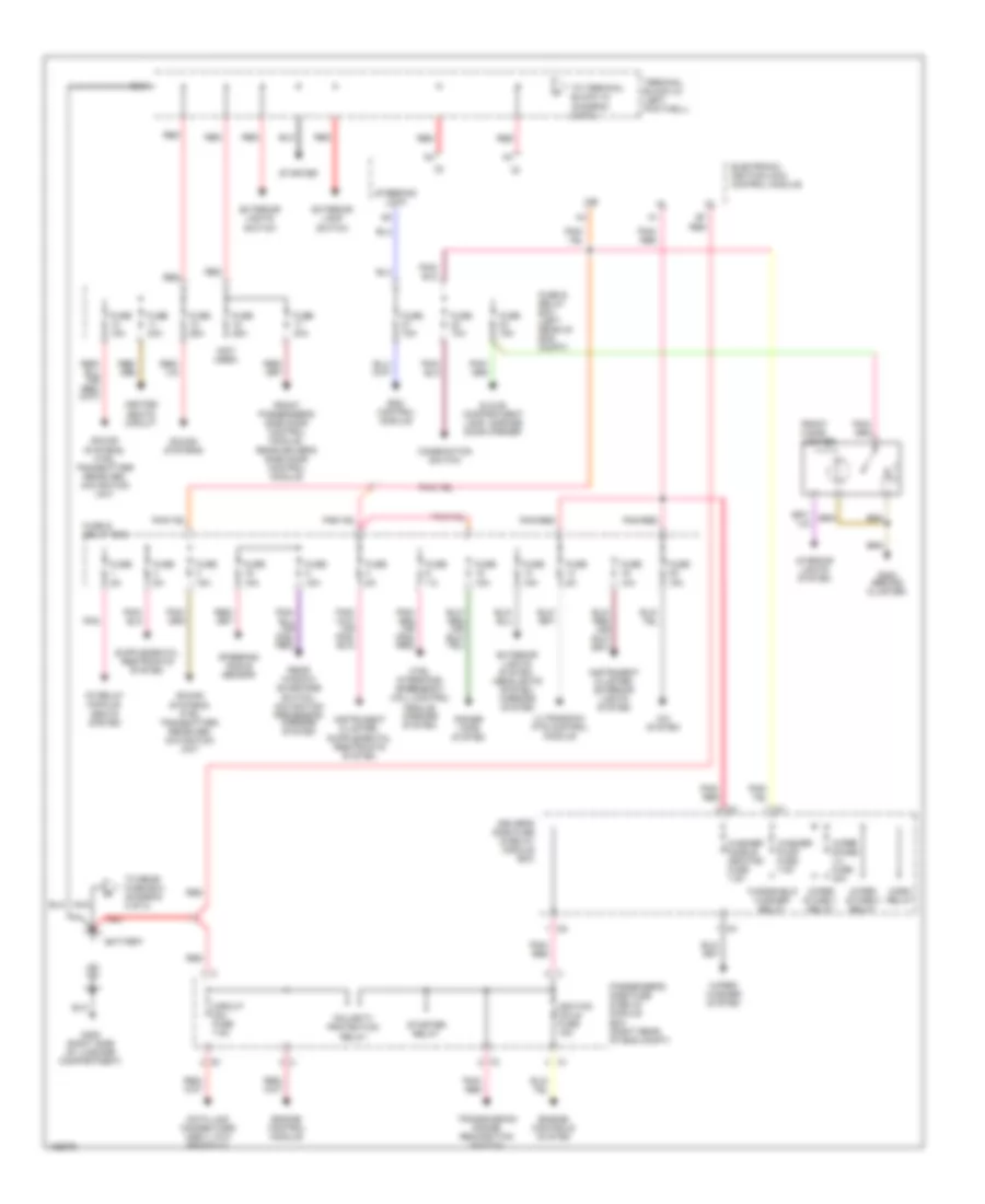
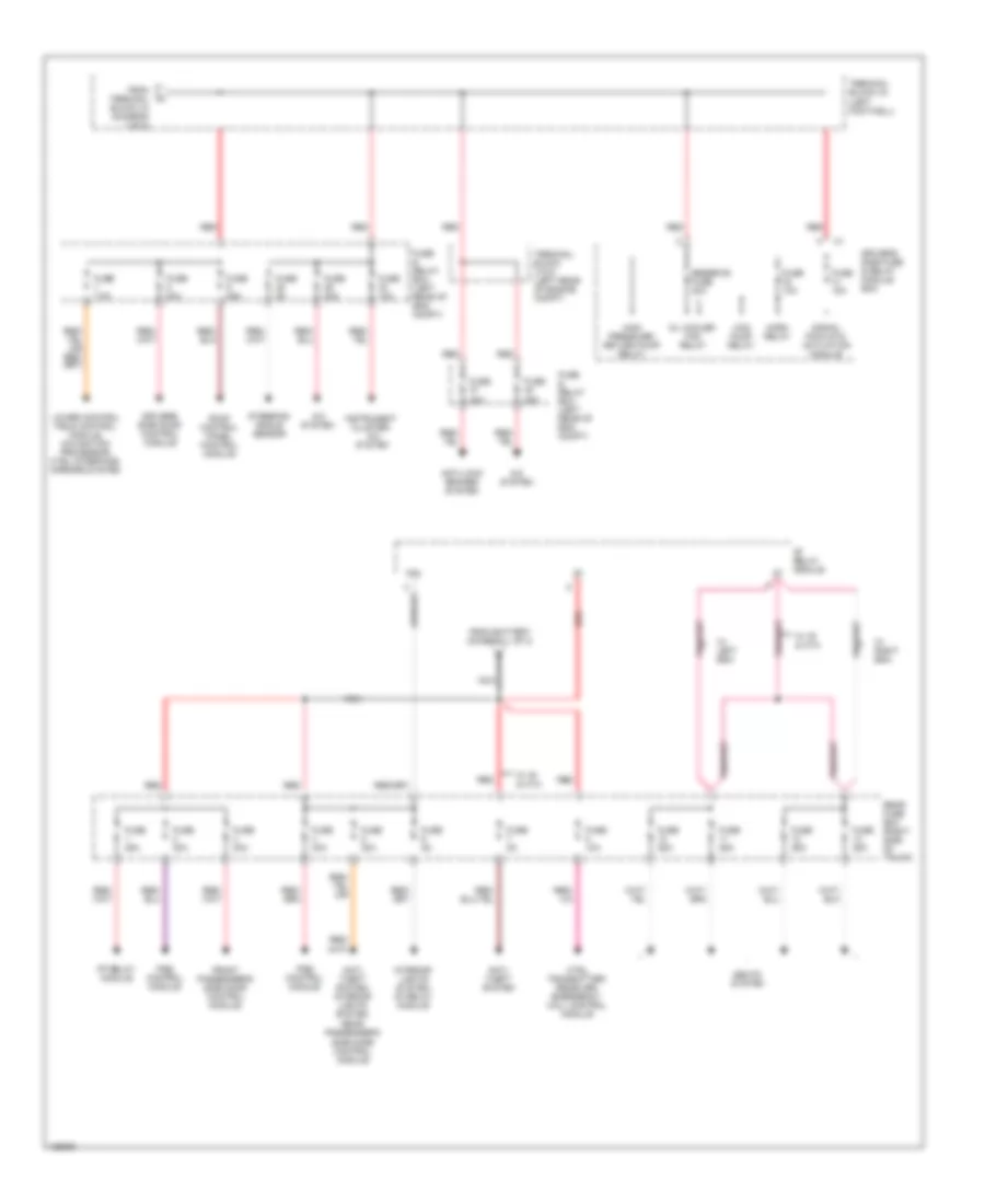
POWER DISTRIBUTION Power Distribution Wiring Diagram (1 of 2) for Mercedes-Benz C280 1999 List of elements for Power Distribution Wiring Diagram (1 of 2) for Mercedes-Benz C280 1999: 64 (not used) 15r A/c system Battery Cf relay module, seats system Circuit fuse 7.5a Combination switch Ctel interface, emergency call control module, mirrors system, Data link connectors (obd ii, dtc readout) Driver's side fuse & relay module box Electronic ignition lock control module Engine control module Engine controls system Esc control module Exterior lamp switch Exterior lights switch Exterior lights system, headlights system, mirrors system Front cigar lighter Front passenger's side door control module, rear driver's side door control module Fuse & relay box Fuse & relay box (left rear of eng compt) Fuse 10a Fuse 15a Fuse 20a Fuse 25a Fuse 2o 15a Fuse 30a Fuse 5a Fuse 7.5 G202 (behind cluster) G405 (right side of luggage compartment) Glove compartment lamp, garage door opener Heated seats circuit Horn relay Ignition coils fuse 15a Instrument cluster, exterior lights system Interior lights system Nca Passenger's side fuse & relay module box (right rear of eng compt) Pnk Pnk/ red Pnk/red Polarity protection relay Power tops system Rear window sunshade switch, navigation processor, mirrors system Red Sound systems Sound systems, ctel transmitter/ receiver, navigation unit Starter Starter relay Steering angle sensor Steering lock Terminal block x4 (left footwell) To rear fuse box (diagram 2 of 2) To terminal block x4 (diagram 2 of 2) Transmission range recognition switch Ultrasonic pts control module Washer nozzle heating fuse 7.5a Washer pump fuse 7.5a Windshield washer relay Wiper stage 1 relay Wiper stage 1-2 fuse 40a Wiper stage 2 relay Wiper/ washer system Power Distribution Wiring Diagram (2 of 2) for Mercedes-Benz C280 1999 List of elements for Power Distribution Wiring Diagram (2 of 2) for Mercedes-Benz C280 1999: 43 30a A/c system Anti- theft system Anti- theft system, interior lights system, Anti-lock brakes system Cf relay module Ctel transmitter- receiver, emergency call control module Driver's side door control module Driver's side fuse & relay module box Fp relay module From battery (diagram 1 of 2) From terminal block x4 (diagram 1 of 2) Front passenger's side door control module Fuse & relay box (left rear of eng compt) Fuse 10a Fuse 15a Fuse 25a Fuse 30a Fuse 40a Fuse 5a Fuse 7.5a Hcs pump relay High pressure/ return pump relay Horn relay Instrument cluster, a/c system Interior lights system, cf relay module Lower control field control module, navigation processor, ctel interface, mirrors system Nca Oil cooler fan relay Pse control module Rear fuse box (right side of trunk) Rear passenger's side door control module Red Reserve fuse 30a Roof control panel control module Seats system Signal pick-up & activation module Steering sngle sensor Terminal block x12/3 (left rear of engine compt) Terminal block x4 (left footwell) W/ ir & ata W/ left esa W/ right esa
POWER DOOR LOCKS Power Door Lock Wiring Diagram for Mercedes-Benz C280 1999 List of elements for Power Door Lock Wiring Diagram for Mercedes-Benz C280 1999: 49 (right wheelhousing, in trunk) g403 17b C230, c280 Can connector Can h Can l Clk320, clk430 Cockpit switch group Computer data lines Driver side door control module Fuse & relay box (left rear of engine compt) Fuse 30a Fuse 40a G300 (left front seat cross- member) G301 (right front seat cross- member) G403 (right whellhousing, in trunk) Ground Hot at all times Ir d Ir u+ Left front door ir receiver Left front door lock/ unlock switch Left front door switch Left rear door switch Lf door Lf lock Lf unlock Lock Lr door Nca Passenger side door control module Pneumatic system equipment (pse) control module (right rear side of trunk) Rear fuse box (right side of trunk) Rf door Rf lock Rf unlock Right front door ir receiver Right front door lock/ unlock switch Right front door switch Right rear door switch Rr door Signal pickup and activation module Sw in Trnk lk Trnk rel Trnk unlk Trunk lid lock switch Trunk release switch Unlk
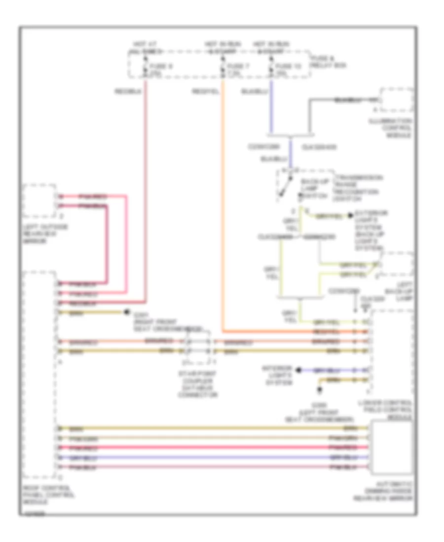
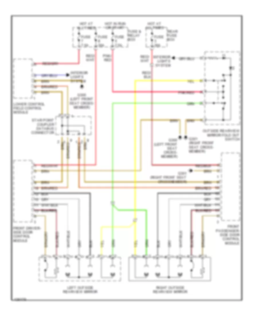
POWER MIRRORS Automatic Day/Night Mirror Wiring Diagram for Mercedes-Benz C280 1999 List of elements for Automatic Day/Night Mirror Wiring Diagram for Mercedes-Benz C280 1999: 23 Automatic dimming inside rearview mirror Back-up lamp switch C230/c280 Clk320/ Clk320/430 Exterior lights system (back-up lights system) Fuse & relay box Fuse 13 15a Fuse 7 7.5a Fuse 9 25a G300 (left front seat crossmember) G301 (right front seat crossmember) Hot at all times Hot in run & start Illumination control module Interior lights system Left back-up lamp Left outside rearview mirror Lower control field control module Pnk/red Roof control panel control module Star point coupler databus connector Transmission range recognition switch Power Mirrors Wiring Diagram for Mercedes-Benz C280 1999 List of elements for Power Mirrors Wiring Diagram for Mercedes-Benz C280 1999: 19 Front driver- side door control module Front passenger- side door control module Fuse & relay box Fuse 30a Fuse 7.5a G300 (left front seat cross- member) G301 (right front seat cross- member) G301 (right front seat crossmember) Hot at all times Hot in run or start Interior lights system Left outside rearview mirror Lower control field control module Outside rearview mirror fold out switch Pnk/ red Pnk/red Rear fuse box Right outside rearview mirror Star point coupler databus connector
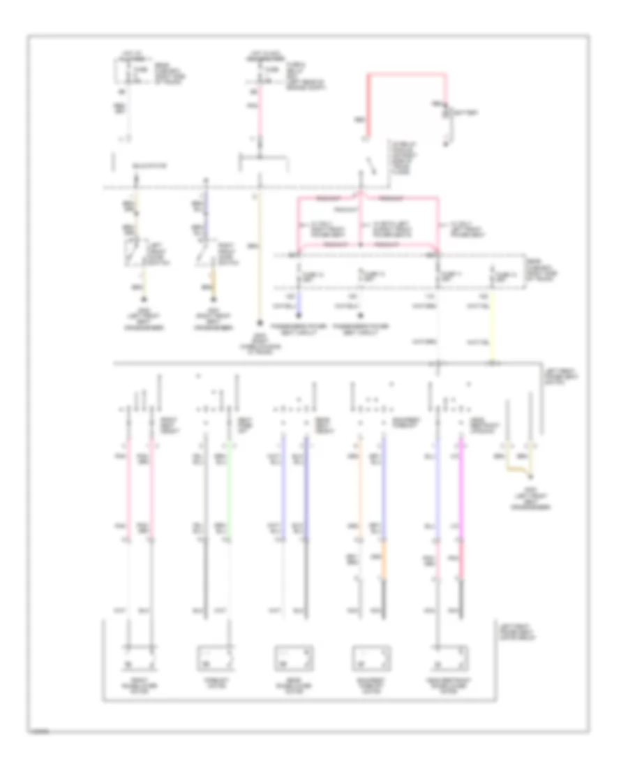
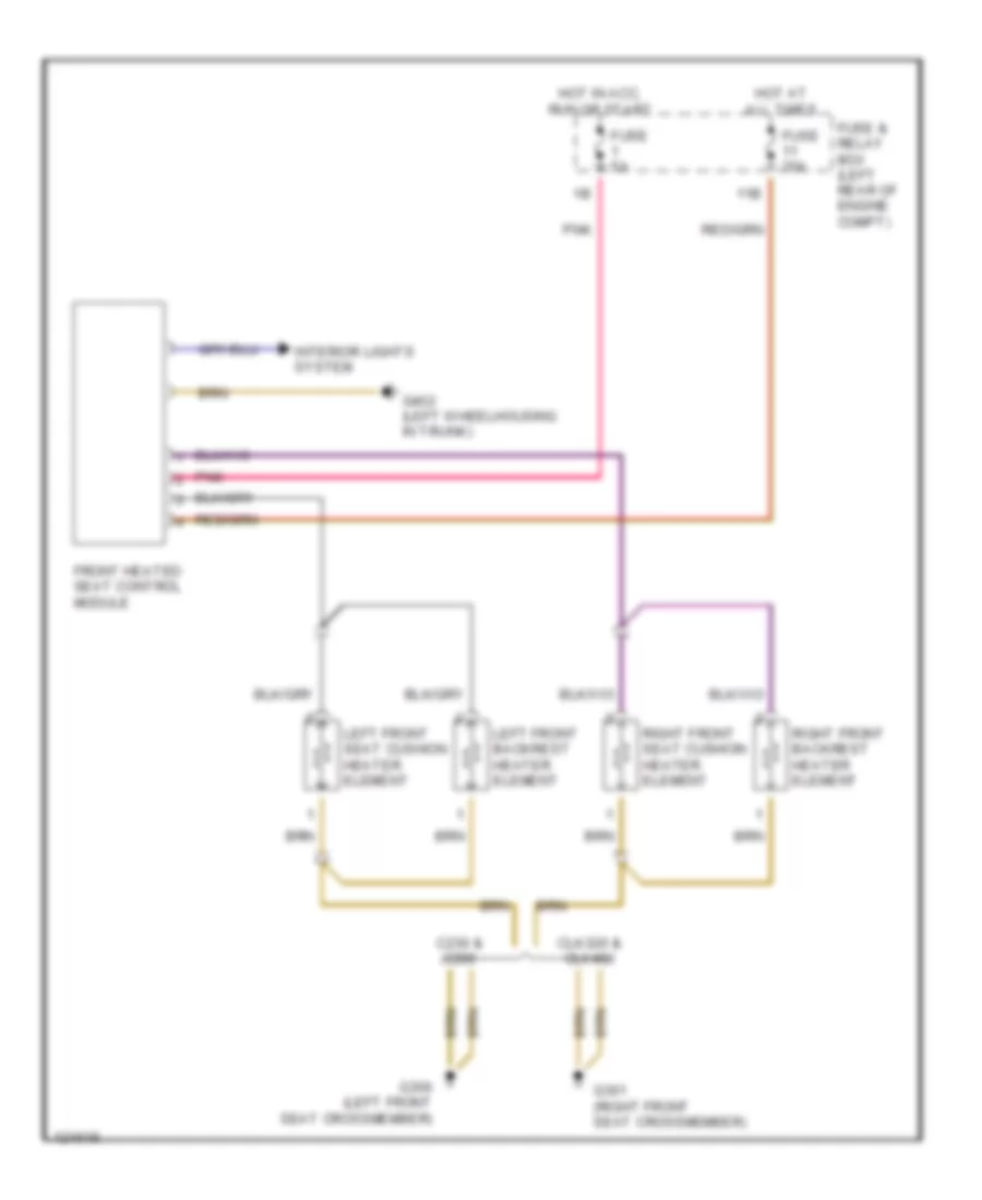
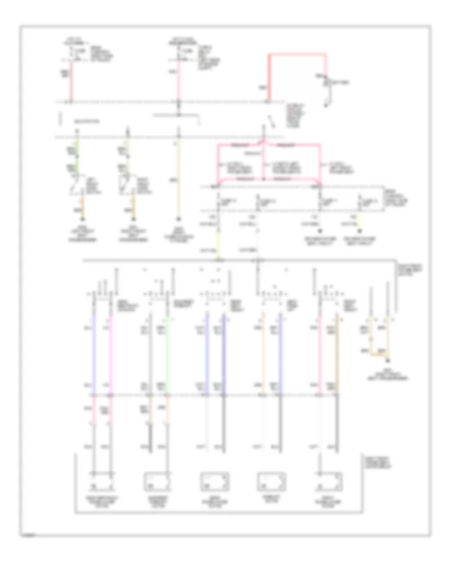
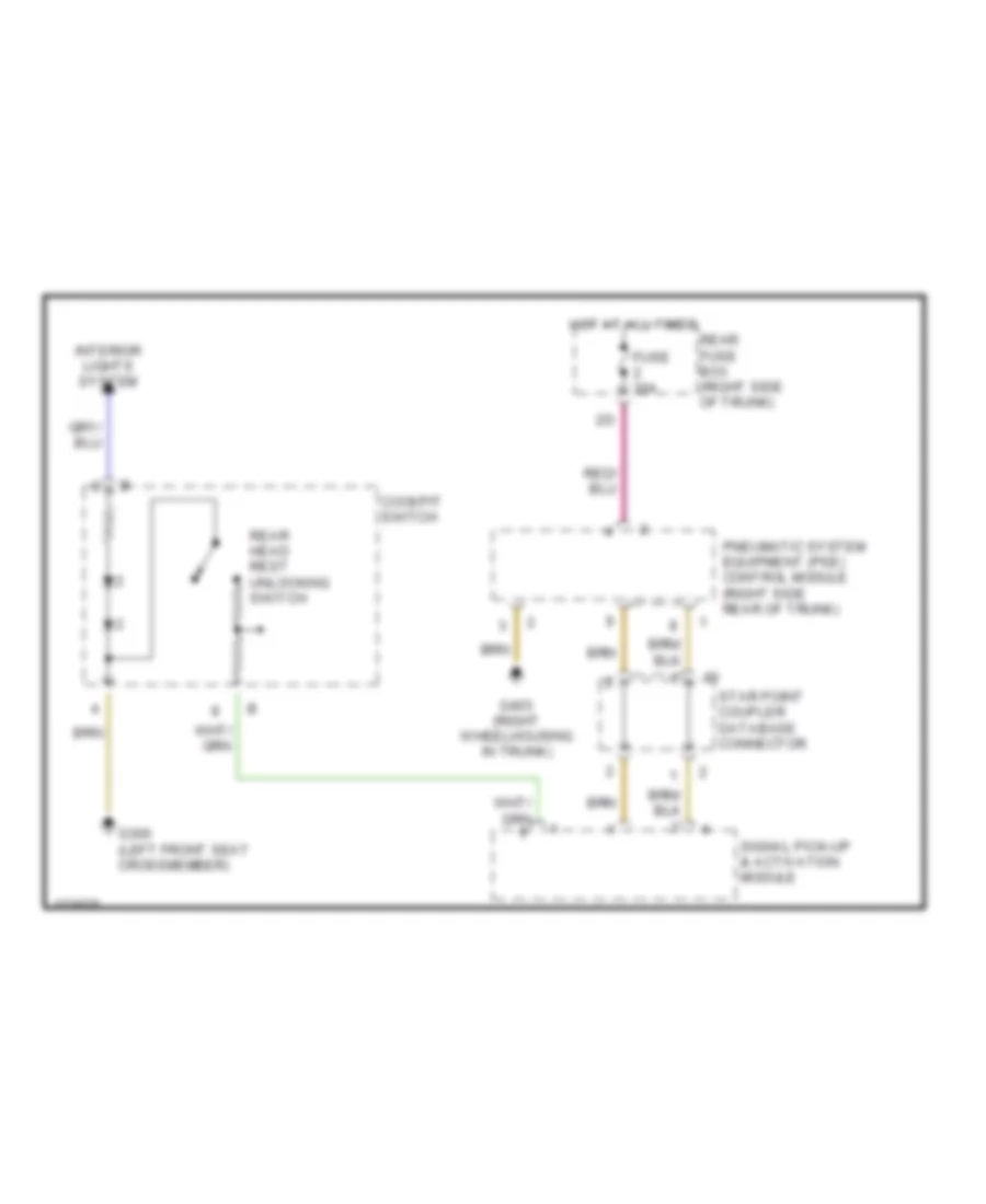
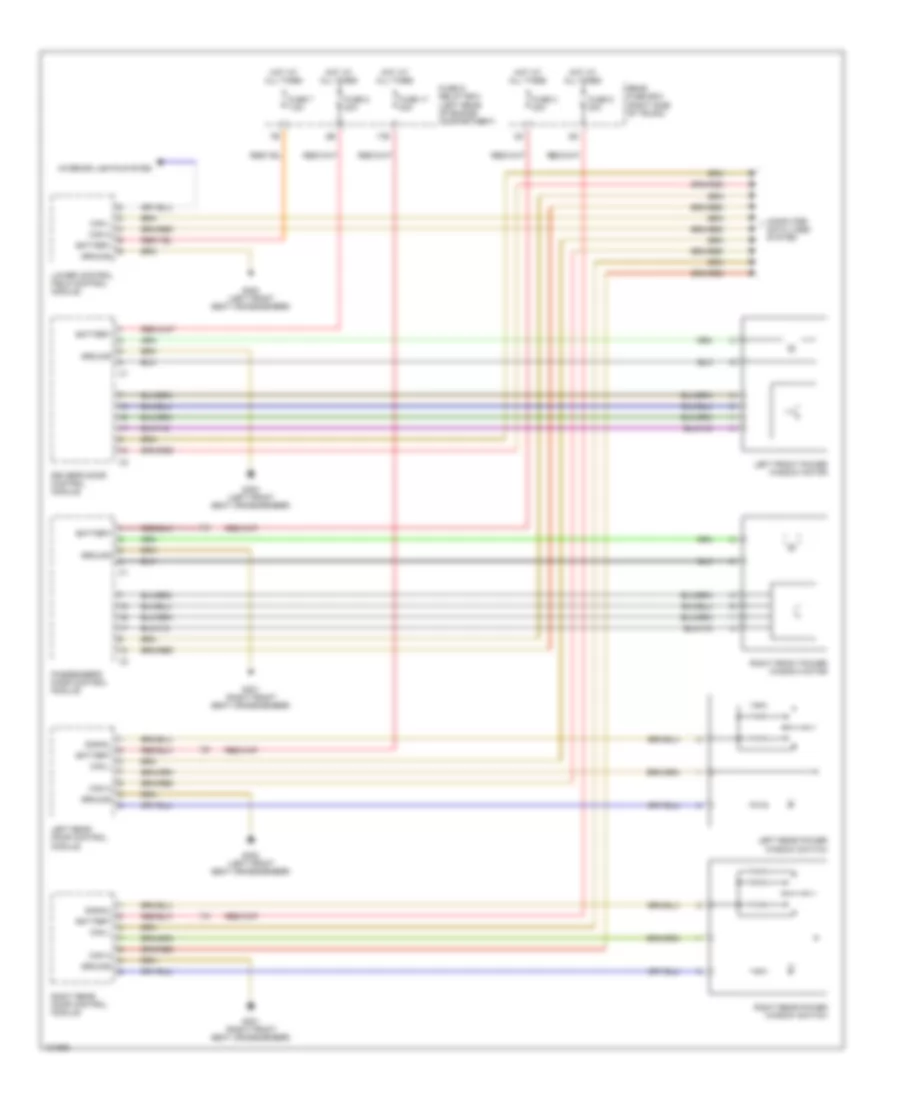
POWER SEATS Driver Power Seat Wiring Diagram for Mercedes-Benz C280 1999 List of elements for Driver Power Seat Wiring Diagram for Mercedes-Benz C280 1999: 41 10d 10e 11d 12d 13d Backrest fore/aft Backrest fore/aft motor Battery Cf relay module (on right side of trunk floor) Fore/aft motor Front raise/lower motor Front seat height Fuse & relay box (left rear of engine compt) Fuse 10 25a Fuse 11 25a Fuse 12 25a Fuse 13 25a Fuse 5a G300 (left front seat crossmember) G301 (right front seat crossmember) G403 (right wheelhousing in trunk) Head restraint raise/lower motor Head restraint up/down Hot at all times Hot in acc, run or start Left front door switch Left front power seat motor group Left front power seat switch Nca Passenger's power seat circuit Pnk Rear fuse box (right side of trunk) Rear raise/lower motor Rear seat height Red Right front door switch Seat fore/ aft Solid state W/ both left & right front power seats W/ only left front power seat W/ only right front power seat Heated Seats Wiring Diagram for Mercedes-Benz C280 1999 List of elements for Heated Seats Wiring Diagram for Mercedes-Benz C280 1999: 18 11b C230 & c280 Clk320 & clk480 Front heated seat control module Fuse & relay box (left rear of engine compt) Fuse 20a Fuse 5a G300 (left front seat crossmember) G301 (right front seat crossmember) G402 (left wheelhousing in trunk) Hot at all times Hot in acc, run or start Interior lights system Left front backrest heater element Left front seat cushion heater element Pnk Right front backrest heater element Right front seat cushion heater element Passenger's Power Seat Wiring Diagram for Mercedes-Benz C280 1999 List of elements for Passenger's Power Seat Wiring Diagram for Mercedes-Benz C280 1999: 43 (right side of trunk) 10d 10e 11d 12d 13d Backrest fore/aft Backrest fore/aft motor Battery Cf relay module (on right side of trunk floor) Driver's power seat circuit Fore/aft motor Front raise/lower motor Front seat height Fuse & relay box (left rear of engine compt) Fuse 10 25a Fuse 11 25a Fuse 12 25a Fuse 13 25a Fuse 5a G300 (left front seat crossmember) G301 (right front seat crossmember) G403 (right wheelhousing in trunk) Head restraint raise/lower motor Head restraint up/down Hot at all times Hot in acc, run or start Left front door switch Nca Pnk Rear fuse box Rear fuse box (right side of trunk) Rear raise/lower motor Rear seat height Red Right front door switch Right front power seat motor group Right front power seat switch Seat fore/ aft Solid state W/ both left & right front power seats W/ only left front power seat W/ only right front power seat Rear Head Restraint Wiring Diagram for Mercedes-Benz C280 1999 List of elements for Rear Head Restraint Wiring Diagram for Mercedes-Benz C280 1999: 11 Cockpit switch Fuse 30a G300 (left front seat crossmember) G403 (right wheelhousing in trunk) Hot at all times Interior lights system Pneumatic system equipment (pse) control module (right side rear of trunk) Rear fuse box (right side of trunk) Rear head rest unlocking switch Signal pick-up & activation module Star point coupler database connector
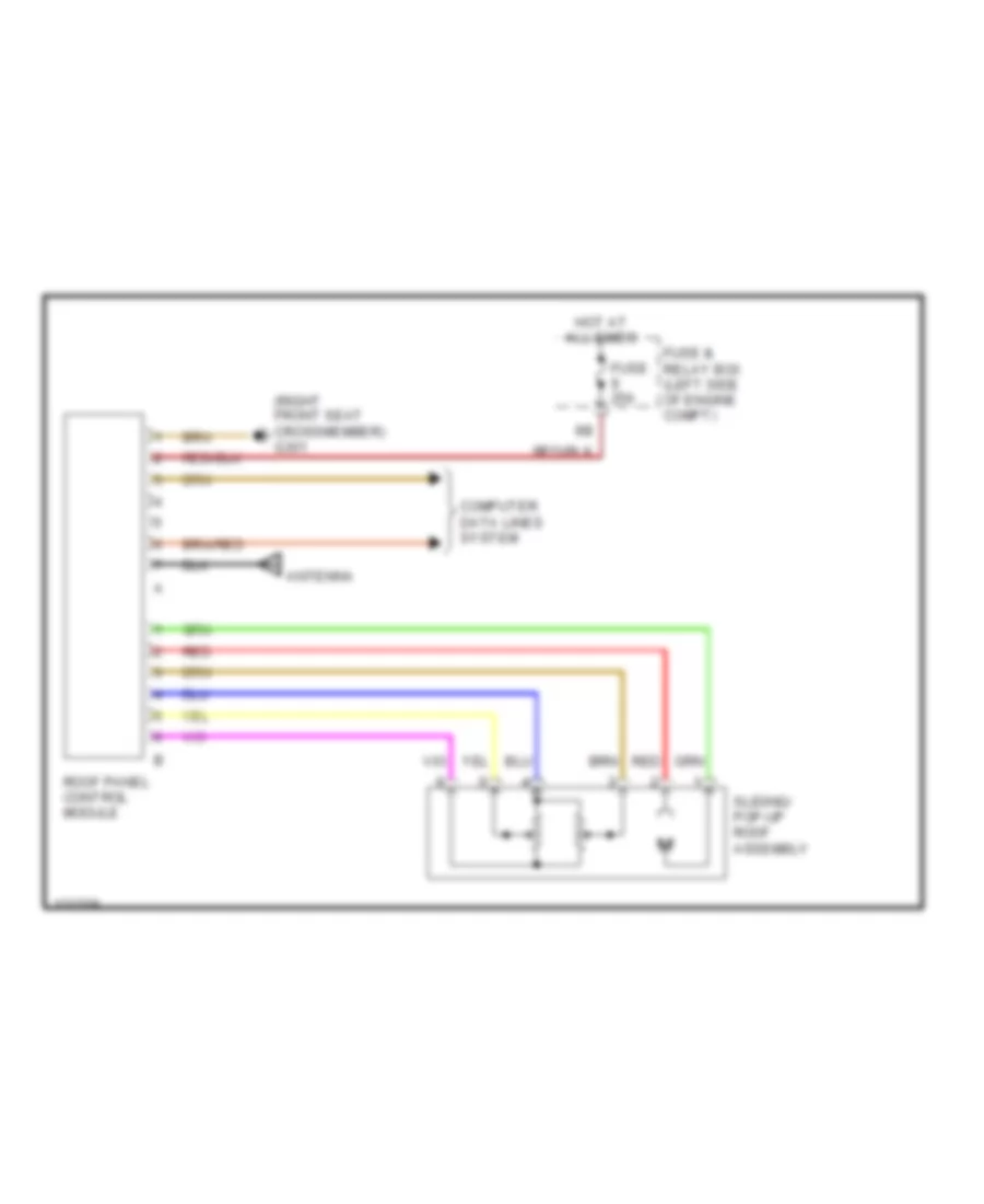
POWER TOP/SUNROOF Power Top/Sunroof Wiring Diagrams for Mercedes-Benz C280 1999 List of elements for Power Top/Sunroof Wiring Diagrams for Mercedes-Benz C280 1999: 9 (right front seat crossmember) g301 Antenna Computer data lines system Fuse & relay box (left side of engine compt) Fuse 25a Hot at all times Red Roof panel control module Sliding/ pop-up roof assembly
POWER WINDOWS Power Window Wiring Diagram for Mercedes-Benz C280 1999 List of elements for Power Window Wiring Diagram for Mercedes-Benz C280 1999: 27 17b Battery Can h Can l Computer data lines system Driver's door control module Fuse & relay box (left rear of engine compartment) Fuse 17 30a Fuse 3 30a Fuse 5 30a Fuse 7 7.5a Fuse 8 30a G300 (left front seat crossmember) G301 (right front seat crossmember) Ground Hot at all times Interior lights system Left front power window motor Left rear door control module Left rear power window switch Lower control field control module Passenger's door control module Rear fuse box (right side of trunk) Right front power window motor Right rear door control module Right rear power window switch Signal
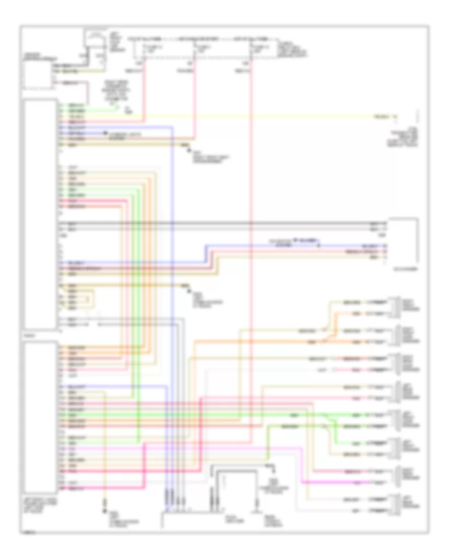
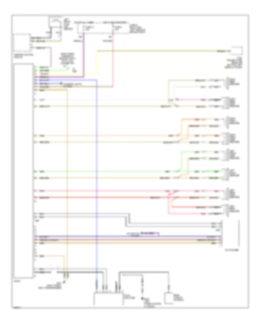
RADIO Radio Wiring Diagrams, with Amplifier for Mercedes-Benz C280 1999 List of elements for Radio Wiring Diagrams, with Amplifier for Mercedes-Benz C280 1999: 33 (right rear corner of engine compt) data link connector 10b 12b Asr/sps control module Cd changer Ctel transmitter- receiver (in bottom left rear of trunk) D2b Fm/am amplifier Fuse & relay box (left rear of engine compt) Fuse 10 15a Fuse 12 25a Fuse 3 15a G301 (right front seat crossmember) G402 (left wheelhousing in trunk) Hot at all times Hot in run or start Interior lights system Left front axle vss sensor Left front door speaker Left front speaker Left rear door speaker Left rear speaker Left/right audio power amplifier (left side of trunk) Navigation system Nca Pnk Radio Rear window antenna Right front door speaker Right front speaker Right rear door speaker Right rear speaker W/ d2b Radio Wiring Diagrams, without Amplifier for Mercedes-Benz C280 1999 List of elements for Radio Wiring Diagrams, without Amplifier for Mercedes-Benz C280 1999: 30 (right rear corner of engine compt) data link connector 10b Asr/sps control module Cd changer Ctel transmitter- receiver (bottom left rear of trunk) D2b Fm/am amplifier Fuse & relay box (left rear of engine compt) Fuse 10 15a Fuse 3 15a G301 (right front seat crossmember) G402 (left wheelhousing in trunk) Hot at all times Hot in run or start Interior lights system Left front axle vss sensor Left front door speaker Left front speaker Left rear door speaker Left rear speaker Navigation system Nca Pnk Radio Rear window antenna Right front door speaker Right front speaker Right rear door speaker Right rear speaker W/ d2b
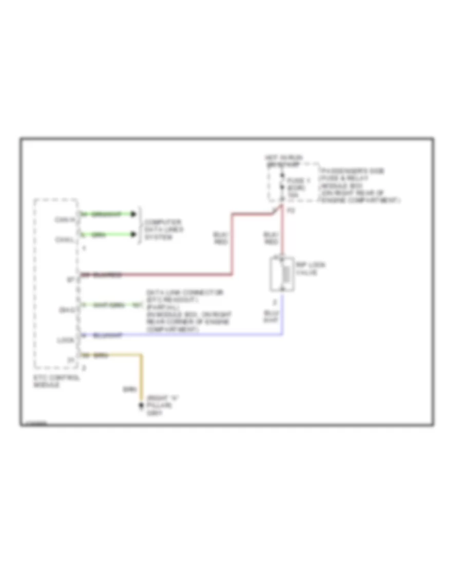
SHIFT INTERLOCKS Shift Interlock Wiring Diagram for Mercedes-Benz C280 1999 List of elements for Shift Interlock Wiring Diagram for Mercedes-Benz C280 1999: 12 (right "a" pillar) g901 Can h Can l Computer data lines system Data link connector (dtc readout) (partial) (in module box, on right rear corner of engine compartment) Diag Etc control module Fuse 1 (edr) 10a Hot in run or start Lock Passenger's side fuse & relay module box (on right rear of engine compartment) R/p lock valve
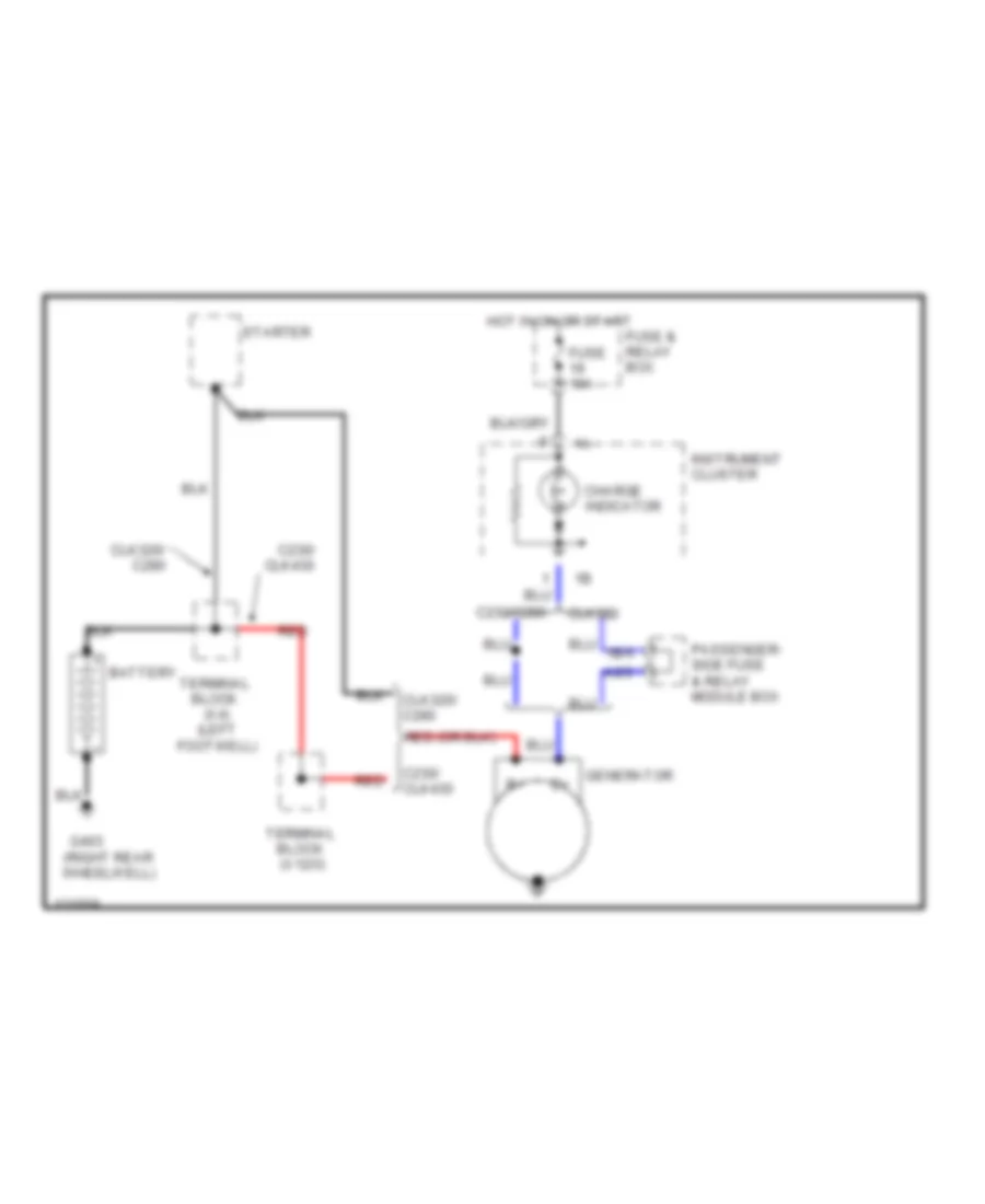
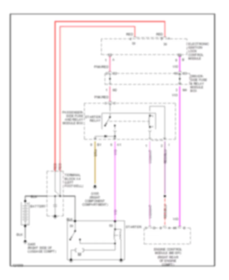
STARTING/CHARGING Charging Wiring Diagram for Mercedes-Benz C280 1999 List of elements for Charging Wiring Diagram for Mercedes-Benz C280 1999: 19 (right rear wheelwell) A2/3 Battery C230/ clk430 C230/c280 Charge indicator Clk320 Clk320/ c280 Fuse & relay box Fuse 10a G403 Generator Hot in on or start Instrument cluster Passenger- side fuse & relay module box Red Starter Terminal block (x12/3) Terminal block (x4) (left footwell) Starting Wiring Diagram for Mercedes-Benz C280 1999 List of elements for Starting Wiring Diagram for Mercedes-Benz C280 1999: 13 (right rear of engine compt) Battery Driver- side fuse & relay module box Electronic ignition lock control module Engine control module (me-sfi) G105 (right component compartment) G405 (right side of luggage compt) Passenger- side fuse and relay module box Pnk/red Red Starter Starter relay Terminal block x4 (left footwell)
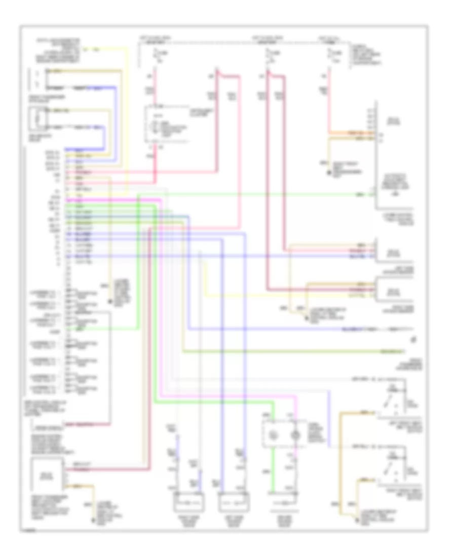
SUPPLEMENTAL RESTRAINTS Supplemental Restraint Wiring Diagram for Mercedes-Benz C280 1999 List of elements for Supplemental Restraint Wiring Diagram for Mercedes-Benz C280 1999: 53 (in module box, on right rear corner of engine compartment) (lower center of dash, at srs control module) g302 (right front seat crossmember) g301 15r Ab, d+ Ab, d- Ab, p+ Ab, p- Acsr Automatic child seat recognition warning lamp Cra out Crash signal D16 Data link connector (dtc readout) (partial) Diag Driver air bag squib Driver etr squib Engine control module (me-sfi) (in module box, on right rear of engine compartment) Etr, d+ Etr, d- Etr, p+ Etr, p- Front passenger air bag squib Front passenger etr squib Front passenger seat occupied recognition w/automatic child seat recognition (ascr) Fuse & relay box (on left rear of engine compartment) Fuse 5a Fuse 7.5a Horn/ air bag clock spring contact Hot at all times Hot in acc, run or start Instrument cluster Jumpered to pins 1 & 2 Jumpered to pins 10 & 11 Jumpered to pins 13 & 14 Jumpered to pins 16 & 17 Jumpered to pins 18 & 19 Jumpered to pins 3 & 4 Jumpered to pins 6 & 7 Left front seat belt buckle switch Left side air bag sensor Left side air bag squib Lower control field control module Nca Ohms Pnk Right front seat belt buckle switch Right side air bag sensor Right side air bag squib Shorting bar Solid state Srs control module (on transmission tunnel, forward of shifter) Srs malfunction indicator lamp
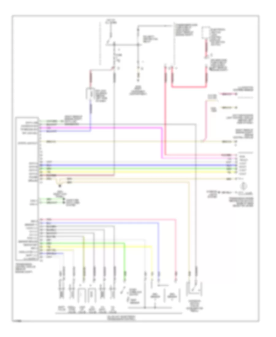
TRANSMISSION A/T Wiring Diagram for Mercedes-Benz C280 1999 List of elements for A/T Wiring Diagram for Mercedes-Benz C280 1999: 63 (right rear of engine compt) data link connector (right rear of engine compt) engine control module 1-2/ 4-5 valve 1-2/4-5 vlv 2-3 shift valve 2-3 vlv 3-4 shift valve 3-4 vlv A out B out C out C2 driver's side fuse & relay module box (left rear of engine compt) C230, c280 Can (+) Can (-) Clk 320 clk 430 Computer data lines system D out Data a Data b Data c Data d Data line Daytime running light control module (behind left side of dash) Electronic ignition lock control module (on ignition switch) Fuse 10a G105 (right component compartment) G203 (right kick panel) Ground Hot at all times Illum Illumination control module Interior lights system Kickdown sw Kickdown switch (top of accelerator pedal) Lock up valve Modul- ator valve Modulator vlv Passenger's side fuse & relay module box (right rear of engine compt) Pnk Pnk/red Polarity protection relay Power Pwm vlv Pwr R/p lock sol R/p lock solenoid (behind left side of dash) Rpm 2 Rpm 3 Rpm sensor Sensor ground Sensor v+ Shift valve Shift vlv Start interlock switch Strtr lock-out Temp sensor Temp/start Tr out Tr recogn sw Transmission control module (rear of engine compt) Transmission range recognition switch (base of gear selector lever) Valve unit (electronic transmission control)
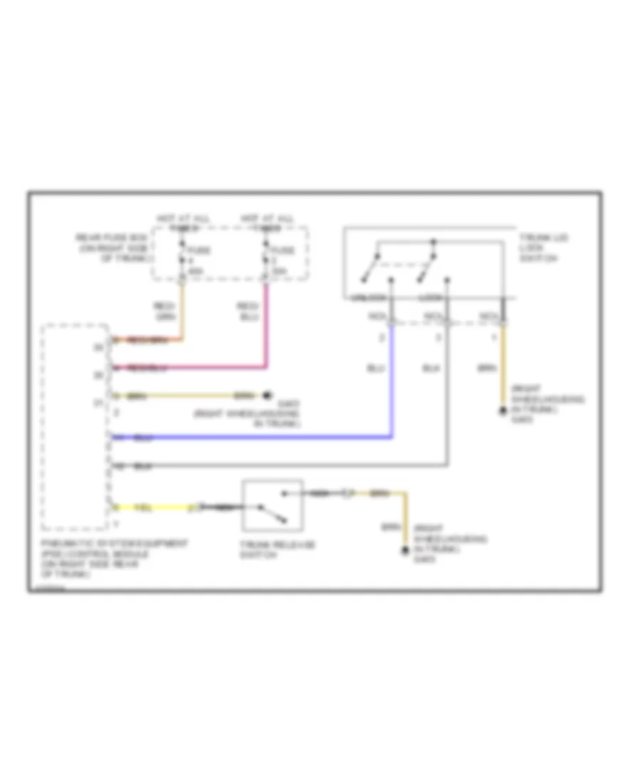
TRUNK, TAILGATE, FUEL DOOR Trunk, Tailgate, Fuel Door Wiring Diagrams for Mercedes-Benz C280 1999 List of elements for Trunk, Tailgate, Fuel Door Wiring Diagrams for Mercedes-Benz C280 1999: 12 (right wheelhousing in trunk) g403 Fuse 30a Fuse 40a G403 (right wheelhousing in trunk) Hot at all times Lock Nca Pneumatic system equipment (pse) control module (on right side rear of trunk) Rear fuse box (on right side of trunk) Trunk lid lock switch Trunk release switch Unlock
WIPER/WASHER Front Wiper/Washer Wiring Diagram for Mercedes-Benz C280 1999 List of elements for Front Wiper/Washer Wiring Diagram for Mercedes-Benz C280 1999: 44 15r 22b Can h Can l Combination switch Driver side fuse & relay module box Electronic ignition lock control module Fuse & relay box (left rear of engine compt) Fuse 10a Fuse 25a G104 (left component compartment) G202 (behind instrument cluster) G301 (right front seat crossmember) Ground Hot at all times Hot in run, acc or start Int Left heated windshield washer nozzle Nca Off Park Pnk Pnk/ red Pnk/red Rain sensor Rear fuse box (right side of trunk) Red Right heated windshield washer nozzle Roof panel control module Sam fuse 15a Signal pickup and activation module Star-point coupler databus connector Terminal block Washer Washer nozzle heating fuse 7.5a Washer pump fuse 7.5a Washer pump motor Washer switch Windshield washer relay Windshield wiper motor Wiper Wiper stage 1-2 fuse 40a Wiper stage relay Wiper switch Headlamp Wiper/Washer Wiring Diagram for Mercedes-Benz C280 1999 List of elements for Headlamp Wiper/Washer Wiring Diagram for Mercedes-Benz C280 1999: 40 22b 24b 24e 58r Can h Can l Combination switch Component compartment) Driver side fuse & relay module box Electronic ignition lock control module Exterior lamp switch Fuse & relay box (left rear of engine compt) Fuse 10a G104 (left G105 (right component compartment) G202 (behind instrument cluster) Ground Hcs pump fuse 10a Hcs relay Head Headlamp cleaning system pump relay Headlamp washer pump Horn fuse 10a Hot at all times Hot in run, acc or start K30 Left headlamp wiper motor Nca Off Park Red Right headlamp wiper motor Run Sam fuse 15a Signal pick-up & activation module Terminal block Wash Washer Washer switch Wiper switch