Diagram sections — 32 (59 total)
AIR CONDITIONING ANTI-LOCK BRAKES ANTI-THEFT COMPUTER DATA LINES COOLING FAN CRUISE CONTROL DEFOGGERS ELECTRONIC POWER STEERING ELECTRONIC SUSPENSION ENGINE PERFORMANCE EXTERIOR LIGHTS GROUND DISTRIBUTION HEADLIGHTS HORN INSTRUMENT CLUSTER INTERIOR LIGHTS MEMORY SYSTEMS PASSIVE RESTRAINTS POWER ANTENNA POWER DISTRIBUTION POWER DOOR LOCKS POWER MIRRORS POWER SEATS POWER TOP/SUNROOF POWER WINDOWS RADIO STARTING/CHARGING SUPPLEMENTAL RESTRAINTS TRANSMISSION TRUNK, TAILGATE, FUEL DOOR WARNING SYSTEMS WIPER/WASHER
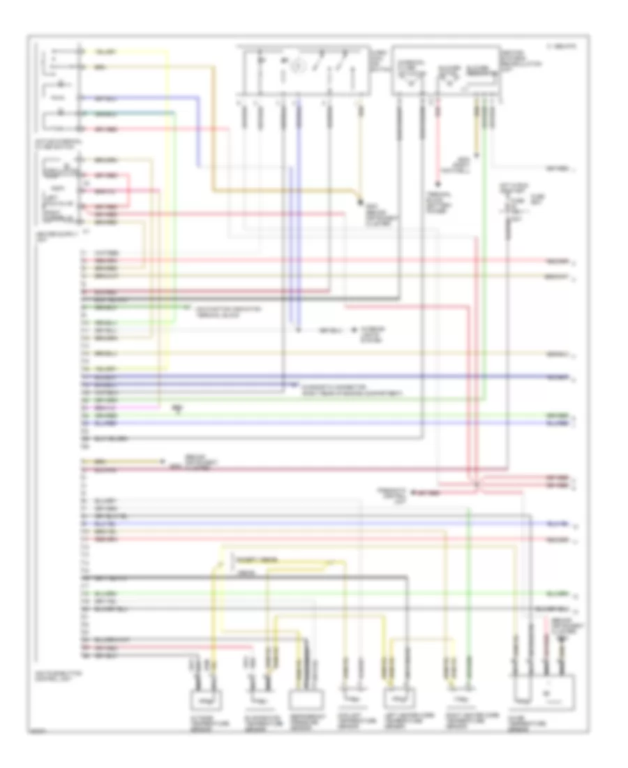
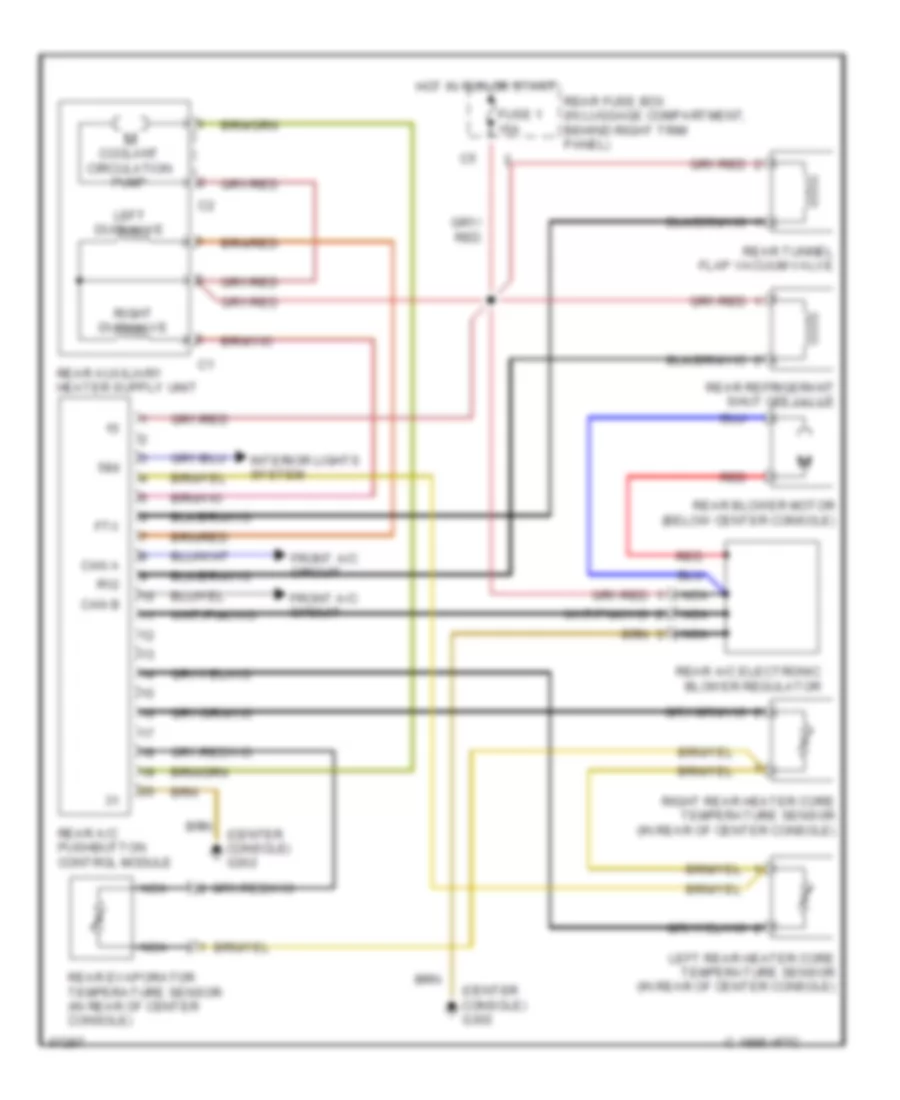
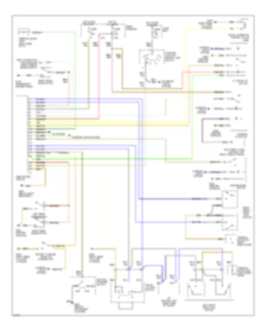
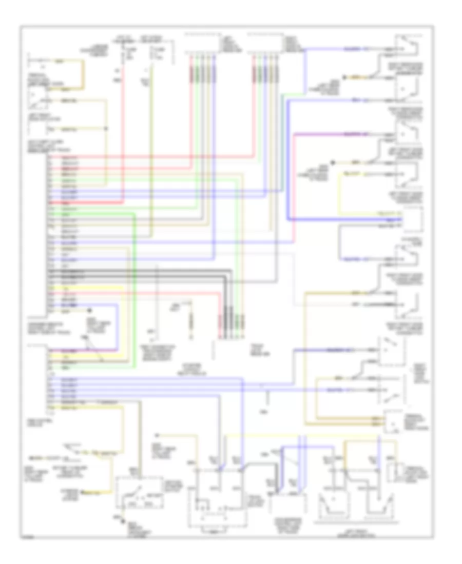
AIR CONDITIONING A/C Wiring Diagram (1 of 2) for Mercedes-Benz S320 1994 List of elements for A/C Wiring Diagram (1 of 2) for Mercedes-Benz S320 1994: 35 (behind instrument cluster) 1995-98 Acc pushbutton control unit Active charcoal filter switch Blower motor Blower regulator C 1995 vftc Charcoal filter actuator Circulation pump Coolant temperature sensor Diagnostic connector (right rear of engine compartment) Evaporator temperature sensor Except 1995-96 Fuse 10a Fuse box G202 G202 (behind instrument cluster) G203 (right footwell) Heating systems recirculation unit Hot in run or start In-car temperature sensor Interior lights system Left duovalve Left heater core temperature sensor Malfunction indication terminal block Nca Outside temperature sensor Pneumatic control unit Red Refrigerant pressure sensor Right duovalve Right heater core temperature sensor S600 Terminal block (battery power) Warm/ cool air switch A/C Wiring Diagram (2 of 2) for Mercedes-Benz S320 1994 List of elements for A/C Wiring Diagram (2 of 2) for Mercedes-Benz S320 1994: 27 (not used) 1995-98 A/c compressor Auxiliary coolant pump control relay (in fuse/relay box) Auxiliary fan preresistor 2nd stage Auxiliary fan relay, stage 1 & 2 (in fuse/relay box) Base module (in module box in right rear of engine compartment) C 1995 vftc Compres- sor clutch Diesel Diode matrix (right footwell) Electronic accelerator/ cruise control/ idle speed control unit Except 1995-98 Fuse 15a Fuse 30a Fuse box G106 (at left headlamp unit) Gasoline Hot at all times Hot in run Left auxiliary fan Maxi-fuse box Nca Right auxiliary fan Rpm sensor S600 Switchover valve unit Rear A/C Wiring Diagram for Mercedes-Benz S320 1994 List of elements for Rear A/C Wiring Diagram for Mercedes-Benz S320 1994: 25 (center console) g302 58d C 1995 vftc Can a Can b Coolant circulation pump Front a/c circuit Ftx Fuse 1 15a Hot in run or start Interior lights system Left duovalve Left rear heater core temperature sensor (in rear of center console) Nca R12 Rear a/c electronic blower regulator Rear a/c pushbutton control module Rear blower motor (below center console) Rear evaporator temperature sensor (in rear of center console) Rear fuse box (in luggage compartment, behind right trim panel) Rear refrigerant shut off valve Rear tunnel flap vacuum valve Red Right duovalve Right rear heater core temperature sensor (in rear of center console)
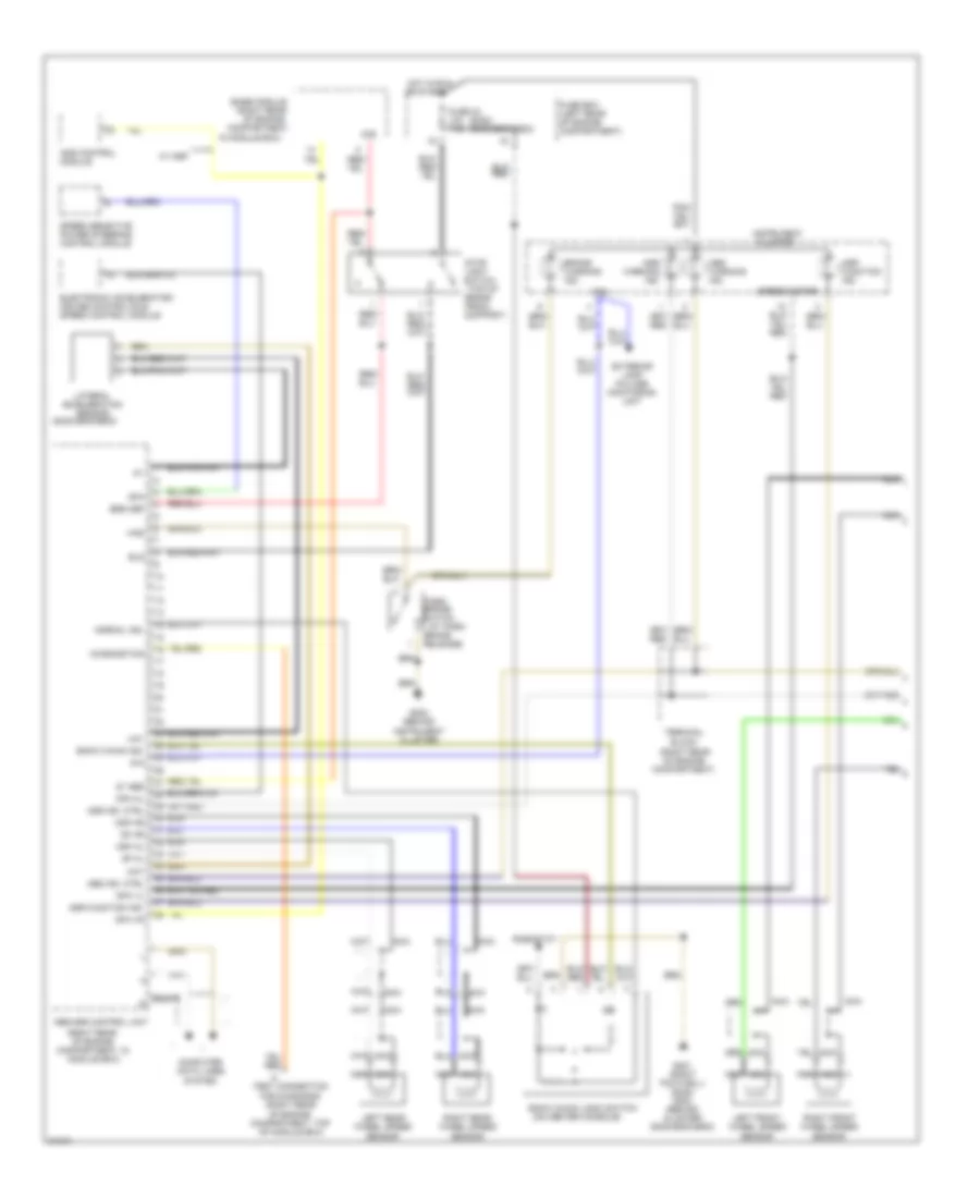
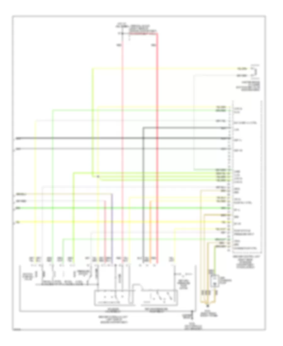
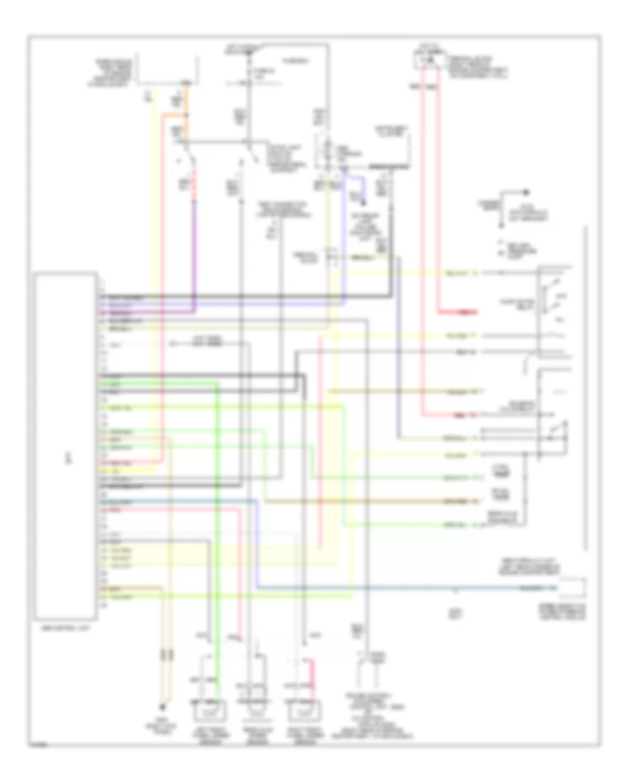
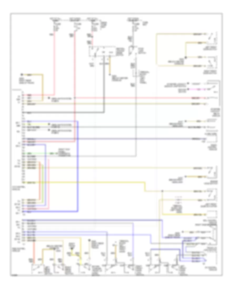
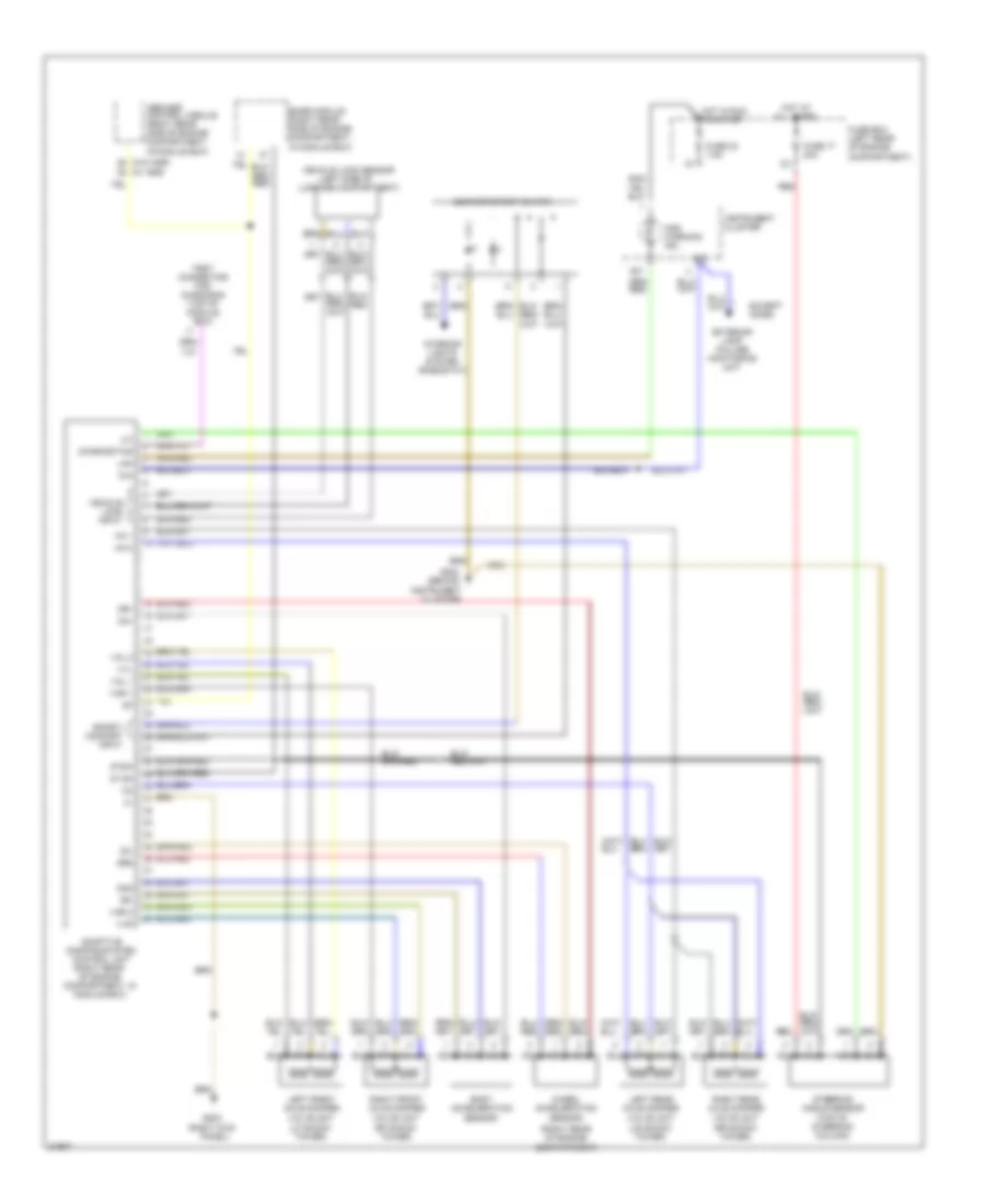
ANTI-LOCK BRAKES Anti-lock Brake Wiring Diagrams, with Acceleration Slip Regulation (1 of 2) for Mercedes-Benz S320 1994 List of elements for Anti-lock Brake Wiring Diagrams, with Acceleration Slip Regulation (1 of 2) for Mercedes-Benz S320 1994: 73 (at park (on center console) (right rear (right rear of engine compartment) (right rear of engine compartment, in module box) (right rear of engine compartment, top of module box) (s320) (s420/s500/s600) (s420/s500/s600) 61e 87 abs 87e Abs ind. ctrl Abs warning ind. Abs/asr control unit Acceleration Ads control module Asr Asr function ind. Asr ind. ctrl Base module Bls Brake Brake pedal Brake warning ind. Brs oef Cluster Compartment, Computer data lines system Df hl Df hr Dfa Dfa hl Dfa vl Dfa vr Diagnostics Electronic accelerator/ cruise control/idle speed control module Exterior lamp failure monitoring unit Fuse 23 10a 7.5a Fuse box (left rear of engine compartment) G201 (right footwell) (s320) g202 (behind cluster) (s420/s500/s600) G202 (behind instrument cluster) Has Hot in run In module box) Ind. Instrument Lateral Left front wheel speed sensor Left rear wheel speed sensor May Mdf hl Mdf hr Nca Normal ind. Of engine Or start Park brake switch Release) Rheostat Right front wheel speed sensor Right rear wheel speed sensor Sensor Snow chain ind. Snow chain logic switch Speed sensitive power steering control module Speedometer Stop light switch (top of Support) Terminal block Test connection for diagnosis Uay W/ asr Warning Anti-lock Brake Wiring Diagrams, with Acceleration Slip Regulation (2 of 2) for Mercedes-Benz S320 1994 List of elements for Anti-lock Brake Wiring Diagrams, with Acceleration Slip Regulation (2 of 2) for Mercedes-Benz S320 1994: 47 (left side of engine compartment) (on hydraulic unit bracket) (right front shock tower) (right rear of engine compartment, in module box) 1.5k ohm 8.2 ohm Abs/asr control unit Abs/asr hydraulic unit Asr charging pump Charge pump ctrl Copper braid Df vl Df vr G100 G103 Grd Hl(a) Hot at all times Hr(a) Lf sol valve Lr sol valve Master brake cylinder switchover valve (s420/s500/s600) Mdf vl Mdf vr Nca Pressure input Pressure switch Pump relay Pump rly ctrl Pump status Red Return/ pressure pump motor Return/pressure Rf sol valve Rr sol valve Solenoid Sw/ over vlv ctrl Switch- over sol valve Terminal block (right rear of engine compartment, on component wall) Uhbz Uvr (a) Uvs (a) Valve relay Vl(a) Vr (a) Vr(a) Vvr Anti-lock Brake Wiring Diagrams, without Acceleration Slip Regulation or Traction Control for Mercedes-Benz S320 1994 List of elements for Anti-lock Brake Wiring Diagrams, without Acceleration Slip Regulation or Traction Control for Mercedes-Benz S320 1994: 57 (left rear corner of engine compartment) (on hydraulic unit bracket) (right kick (right rear (right rear of (right rear of engine compartment, in module box) (s320) (s350) (s350) (s320) 61e 87e Abs control unit Abs hydraulic unit Abs warning ind. Base module Braid Cc control Cluster Compartment, Control unit Copper Cruise control/ Engine compartment, on component wall) Exterior lamp failure monitoring unit Fuse 23 10a Fuse box G116 G203 Hot at all times Hot in run Idle speed In module box) Instrument Left front wheel speed sensor Lf sol valve Module Nca Of engine Or start Panel) Pnk Pressure m Pump Pump motor relay Rear axle sol valve Rear axle speed sensor Red Return/ Rf sol valve Right front wheel speed sensor S320 only Solenoid valve relay Speed sensitive power steering control module Speedometer Stop light switch (top of brake pedal support) Terminal block Test connection for diagnosis (top of module box)
ANTI-THEFT Anti-theft Wiring Diagram for Mercedes-Benz S320 1994 List of elements for Anti-theft Wiring Diagram for Mercedes-Benz S320 1994: 55 (behind right headlamp) (below center console) (right kick panel) diagnostic connector (right rear side of trunk) 56b 58l 58r Alarm horn Ata control module Central locking inside switch Cf control module Df hd Df-hd Engine hood switch Fuse 20a 32/2 Fuse 25a Fuse 7.5a Fuse box G107 G302 G302 (below center console) G405 G405 (right rear side of trunk) Headlights system (fuse 12) Headlights system (fuse 8) Headlights system (fuse 9) Hot at all times Hot in run or start Ignition switch Ircl control module (right side of trunk) Left front door actuator Left front door lock switch Left front door switch Left rear door switch Nca Pse control module Radio control module Rear fuse box Red Right front door lock switch Right front door switch Right rear door switch Right trunk lamp Rotary tumbler/ trunk lid micro- switch Sn 1 Sn 2 Sn1 Starter lock-out relay module Starter lockout/ backup lamp switch Stop lamp switch Terminal block x21/1 (left kick panel) Terminal block x8/6 (left front door) Terminal block x8/7 (right front door) Trunk lid lock switch X42
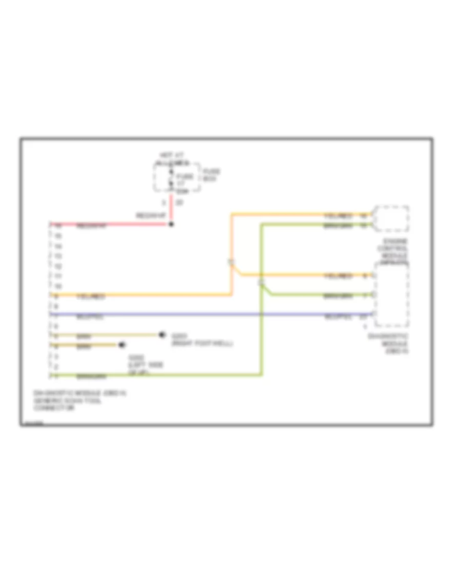
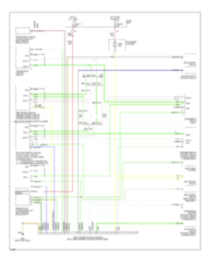
COMPUTER DATA LINES Diagnostic Socket Wiring Diagram for Mercedes-Benz S320 1994 List of elements for Diagnostic Socket Wiring Diagram for Mercedes-Benz S320 1994: 8 Diagnostic module (obd ii) Diagnostic module (obd ii) generic scan tool connector Engine control module (hfm-sfi) Fuse 20a Fuse box G202 (left side of i/p) G203 (right footwell) Hot at all times Test Connector Wiring Diagram for Mercedes-Benz S320 1994 List of elements for Test Connector Wiring Diagram for Mercedes-Benz S320 1994: 36 (1994) (1995-96) (in module box, on right rear of engine compt) A/c pushbutton control module Abs control module/ abs/asr control module/ asr/sps control module/ ets/sps control module Ads control module (in module box, on right rear of engine compt) Ata control module (on right side of luggage compt) Base module (in module box, on right rear of engine compt) Can Can h+ Can l- Cc/isc control module Convenience feature control module (on right side of luggage compt) Diagnogstic module (obd ii) Ea/cc/isc control module/ Engine control module (hfm-sfi) Fuse 15 15a Fuse 17 20a Fuse box G203 (right footwell) Hot at all times Hot in run or start Infrared remote control module (on right side of luggage compt) Instrument cluster Nca Pse control module (right side of rear seat) See system diagram for pin number Sps control module Srs control module Srs ind Test connector for diagnosis (right rear corner of engine compartment) Transmission control module W/ asr W/ electronic accelerator W/o asr W/o electronic accelerator
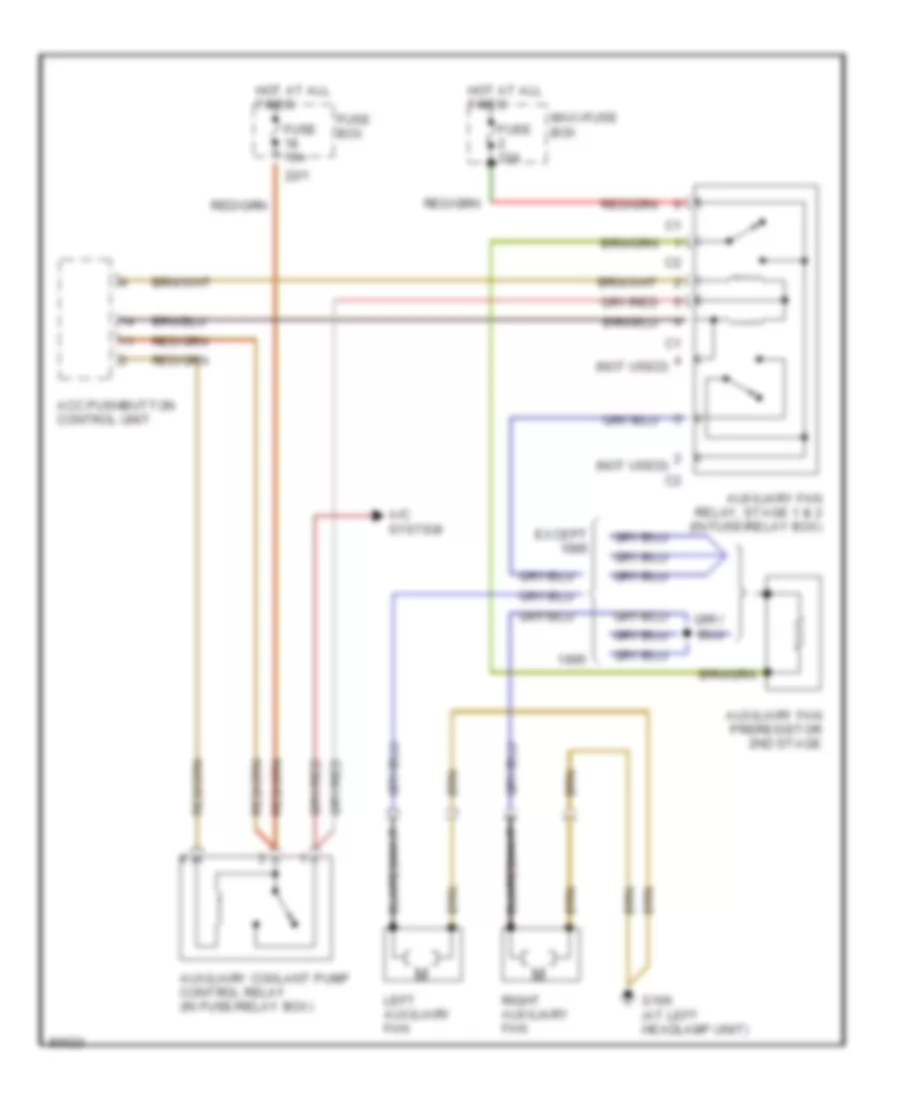
COOLING FAN Cooling Fan Wiring Diagram for Mercedes-Benz S320 1994 List of elements for Cooling Fan Wiring Diagram for Mercedes-Benz S320 1994: 16 (not used) 22/1 A/c system Acc pushbutton control unit Auxiliary coolant pump control relay (in fuse/relay box) Auxiliary fan preresistor 2nd stage Auxiliary fan relay, stage 1 & 2 (in fuse/relay box) Except Fuse 15a Fuse 30a Fuse box G106 (at left headlamp unit) Hot at all times Left auxiliary fan Maxi-fuse box Right auxiliary fan
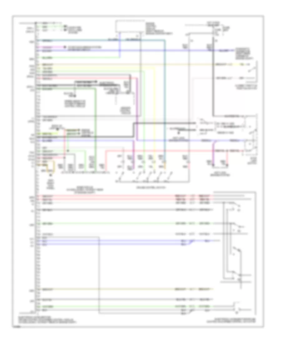
CRUISE CONTROL Cruise/Idle Speed Control Wiring Diagram for Mercedes-Benz S320 1994 List of elements for Cruise/Idle Speed Control Wiring Diagram for Mercedes-Benz S320 1994: 36 (in module box, on right rear of engine compt) cruise control/ idle speed control module (right kick panel) g203 (right rear corner of engine compt) diagnostic connector 87ug 87z Abs control module Aus Base module (right rear of engine compt) Can h+ Can l- Computer data lines system Cruise control switch Cruise control/ idle speed control module (in module box, on right rear of engine compt) Cruise control/idle speed control actuator Df aha Engine control module (right rear of engine compt) Fuse 10a Fuse box Hot film maf sensor Hot in run or start Instrument cluster Ipa Ipdk Ksk Llk Lsk Nca Red S+b S-b Speed meter Ssa Starting circuit Stop lamp switch Tna Usk Electronic Accelerator/Cruise/Idle Speed Control Wiring Diagram for Mercedes-Benz S320 1994 List of elements for Electronic Accelerator/Cruise/Idle Speed Control Wiring Diagram for Mercedes-Benz S320 1994: 46 (1994) (1995-96) 1995-96 w/ ads 87ug 87z Anti-lock brakes system Asr/sps control module Back up lamp switch Base module (in module box, on right rear of engine compt) Bls Can h+ Can l- Closed throttle position switch Computer data lines system Cruise control switch Dfahl Dfavl Diagnostic connector (right rear corner of engine compt) Electronic accelerator/ cruise control/idle speed control module (in module box, on right rear of engine compt) Electronic accelerator/cruise control/idle speed control actuator Electronic speedometer Engine control module (right rear of engine compartment) Engine controls system Ex 1995 w/ ads Fuse 10a Fuse box G203 (right kick panel) Hot in run or start Ips Ksk Lsk M1+ M1- Msk Nca Pks Red S+b S-b Speed sensitive power steering control module Sps Ssa Starting/charging system (starting circuit) Stop lamp switch Tna Upks Usk
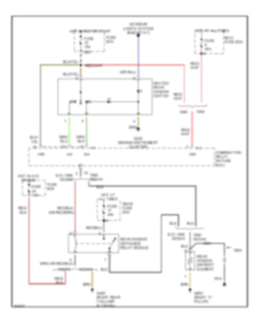
DEFOGGERS Defogger Wiring Diagram for Mercedes-Benz S320 1994 List of elements for Defogger Wiring Diagram for Mercedes-Benz S320 1994: 25 15r 20/2 30h Combination relay (in fuse box) Coupe Exc 1995 sedan Fuse 15a Fuse 40a Fuse 7.5a Fuse box G202 (behind instrument cluster) G405 (right rear taillamp, in trunk) G905 (right "c" pillar) Heated rear window switch Hot at all times Hot in acc or run Hot in run or start Interior lights system (rheostat) Maxi fuse box Nca Off Rear fuse box Rear window defogger relay module Rear window defrost element Sedan
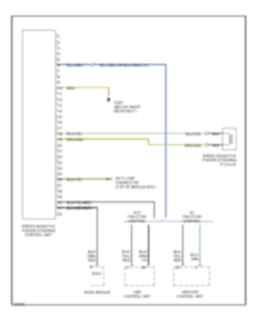
ELECTRONIC POWER STEERING Electronic Power Steering Wiring Diagram for Mercedes-Benz S320 1994 List of elements for Electronic Power Steering Wiring Diagram for Mercedes-Benz S320 1994: 11 87sa Abs control unit Abs/asr control unit Base module Data link connector (top of module box) G303 (below right rear seat) Nca Speed sensitive power steering control unit Speed sensitive power steering p-valve W/ traction control W/o traction control
ELECTRONIC SUSPENSION Electronic Suspension Wiring Diagram for Mercedes-Benz S320 1994 List of elements for Electronic Suspension Wiring Diagram for Mercedes-Benz S320 1994: 64 (behind (left side of (lf shock tower) (lr shock tower) (rf shock tower) (right kick (right rear of engine compartment) (rr shock tower) (top of steering column) (w/ asr) (w/o asr) 4d1 61e 87 sa 87isa Abs/asr control module (right rear side of engine compartment, in module box) Adaptive damping system control unit (right rear of engine compartment, in module box) Ads warning ind. Base module (right rear side of engine compartment, in module box) Body acceleration sensor Cluster) Comfort/sport switch Diagnostics Except 300sd Exterior lamp failure monitoring unit Fuse 17 20a Fuse 23 7.5a Fuse box (left rear of engine compartment) G202 G203 Ha 1 Ha 2 Hot at all times Hot in run or start Instrument Instrument cluster Interior lights system (rheostat) Lam Left front axle damper valve unit Left rear axle damper valve unit Luggage compartment) Nca Panel) Red Right front axle damper valve unit Right rear axle damper valve unit Sport/ comfort input Steering angle sensor Test connector for diagnosis (top of module box) Val 1 Val 2 Var 1 Var 2 Vehicle load input Vehicle load sensor Vvl Vvr Wheel acceleration sensor Za+ Za- Zas Zr+ Zr- Zrs
ENGINE PERFORMANCE
3.2L 3.2L, Engine Performance Wiring Diagrams (1 of 2) for Mercedes-Benz S320 1994 List of elements for 3.2L, Engine Performance Wiring Diagrams (1 of 2) for Mercedes-Benz S320 1994: 52 (behind instrument cluster) (right 5-speed Abs control unit Abs/ asr control unit Accy Automatic Base module (gm) Block Camshaft position sensor Coil wire Control unit Control valve Crankshaft position sensor Distributor Ezl/akr ignition control unit Fuel pump Fuel pumps relay Fuse 30a Fuse 7.5a Fuse box G100 (left front wheel well) G201 kick panel) G206 G310 (right rear seat) Hot at all times Ignition switch Instrument cluster system Kick- down valve Kickdown switch/ transmission mode Knock sensor 1 (right) Knock sensor 2 (left) Lh control unit Lock Nca Rear fuse box Red Reference resister Run S shield Selector lever position switch Shield Spark plugs Speed sensitive power steering Start Starting system (starter) Terminal Transmission control unit Transmission overload protection switch Valve block W/ asr W/o asr 3.2L, Engine Performance Wiring Diagrams (2 of 2) for Mercedes-Benz S320 1994 List of elements for 3.2L, Engine Performance Wiring Diagrams (2 of 2) for Mercedes-Benz S320 1994: 43 (right kick panel) g201 Actuator Air Air mass sensor Air pump injection switchover Camshaft Clutch Coolant Diagnostic socket Egr Electro- magnetic injection air pump Fuel injectors Fuse 17 20a Fuse 24 7.5a Fuse box G100 (left front wheelwell) G101 (near right head- lamp) G110 (left front of engine) Heated oxygen sensor Hot at all times Hot in run or start Injection Intake air Lh control unit Nca No.1 No.2 No.3 No.4 No.5 No.6 Purge Relay Sensor Shield Solenoid/ switchover Solid state Switchover Tdc sensor Temperature Timing Upshift delay Valve
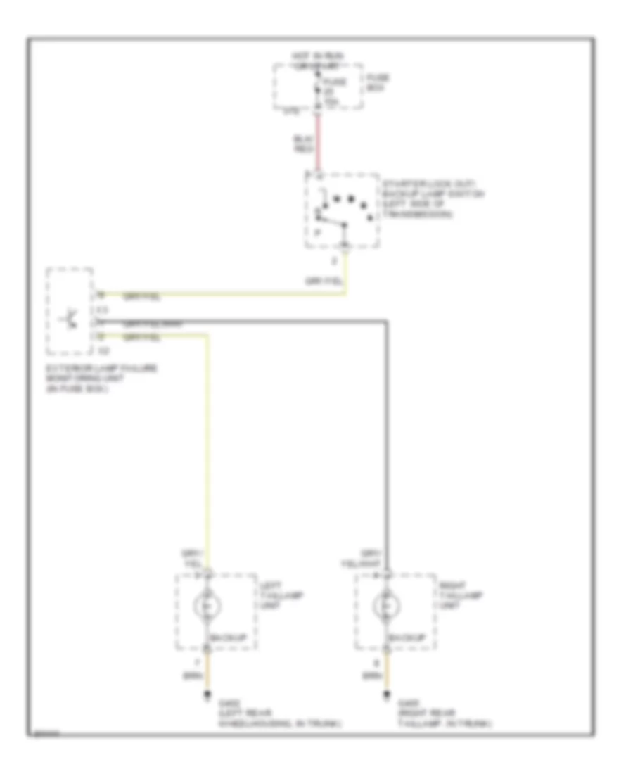
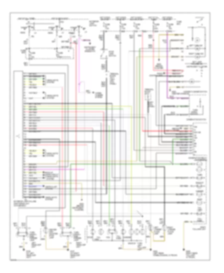
EXTERIOR LIGHTS Back-up Lamps Wiring Diagram for Mercedes-Benz S320 1994 List of elements for Back-up Lamps Wiring Diagram for Mercedes-Benz S320 1994: 11 37/2 Backup Exterior lamp failure monitoring unit (in fuse box) Fuse 15a Fuse box G402 (left rear wheelhousing, in trunk) G405 (right rear taillamp, in trunk) Hot in run or start Left taillamp unit Right taillamp unit Starter lock out/ backup lamp switch (left side of transmission) Exterior Lamps Wiring Diagram for Mercedes-Benz S320 1994 List of elements for Exterior Lamps Wiring Diagram for Mercedes-Benz S320 1994: 71 (1994) (behind inst cluster) g202 15c 22/2 22/3 36/2 37/2 58l 58r A10 A14 B13 Back-up lamps circuit Backup Center high mounted stop lamp Combination relay (in fuse box) Combination switch Ext lamp Exterior lamp failure monitoring unit (in fuse box) Exterior lamp switch Failure ind Fog Fuse 15a Fuse 20a Fuse 7.5a Fuse 7.5a 5/1 Fuse box G106 (at left headlamp unit) G107 (at right headlamp unit) G202 (behind cluster) G202 (behind instrument cluster) G302 (center console) G402 (left rear wheelhousing, in trunk) G405 (right rear taillamp, in trunk) Hazard flasher switch Head Headlights system Hot at all times Hot in accy, run or start Hot in off & accy Hot in run or start Instr clust system Instrument cluster Instrument cluster (rheostat) K30 K30 wb Left headlamp unit Left license plate lamp Left turn ind Marker Off P30 Park Radio control unit Red Right headlamp unit Right license plate lamp Right taillamp unit Right turn ind Stop Stop lamp switch Tail Tail (1994) Tail/ park Terminal block x21/1 (left kick panel) Terminal block x4/17 Turn Turn left taillamp unit Turn signal switch Turn signal/ side marker lamp Wiper/ washer system
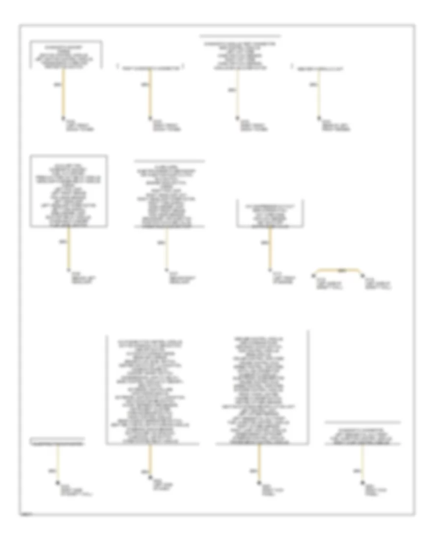
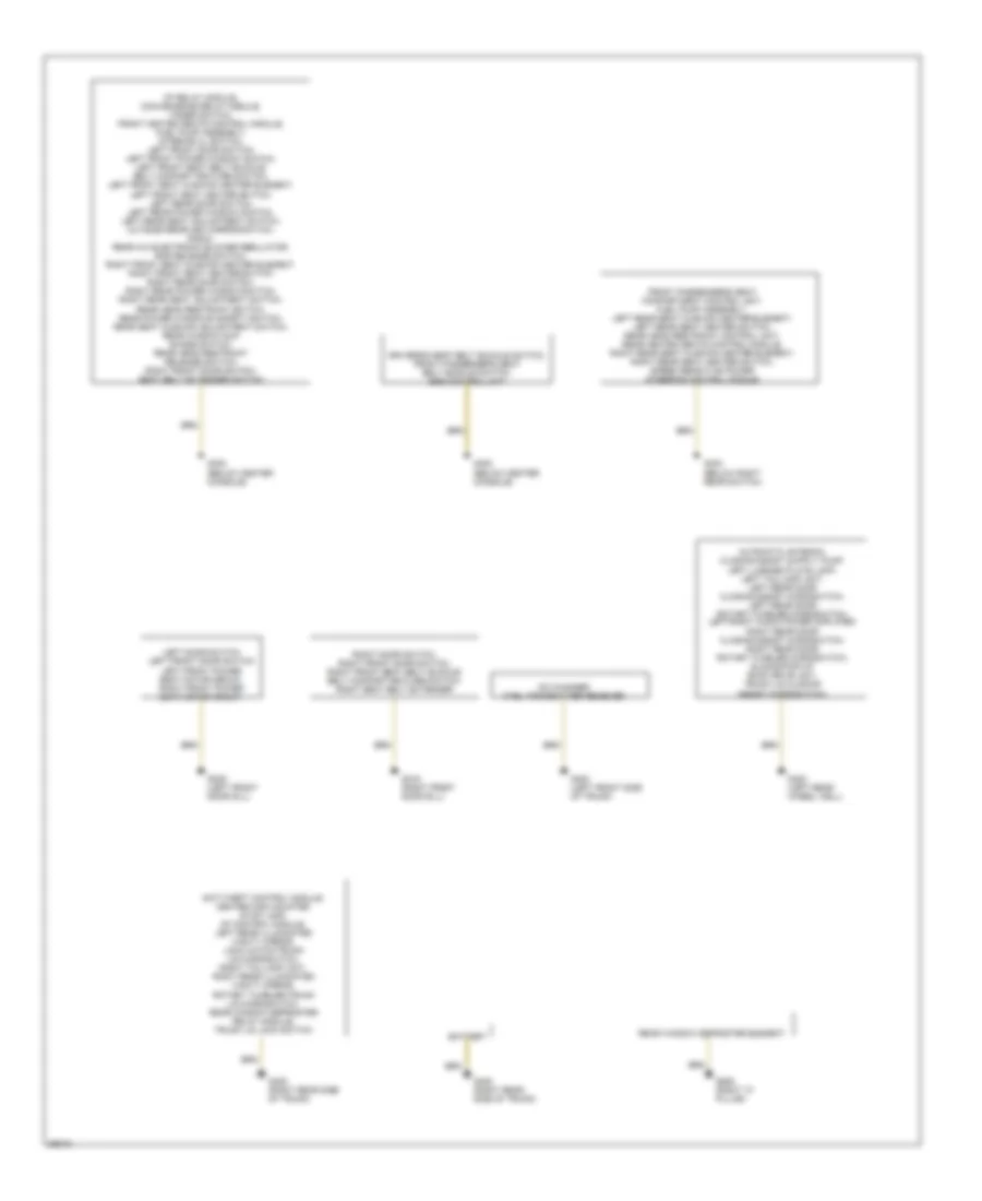
GROUND DISTRIBUTION Ground Distribution Wiring Diagram (1 of 2) for Mercedes-Benz S320 1994 List of elements for Ground Distribution Wiring Diagram (1 of 2) for Mercedes-Benz S320 1994: 21 A/c compressor cut-out/ egr microswitch, hot wire mass air flow sensor, key shut-off switchover valve A/c pushbutton control module, active charcoal filter switch, asr off switch, automatic dimming inside rearview mirror, brake fluid level switch, center air outlet illumination, combination relay, comfort sport switch, dome/reading lamp (w/ delay), emsc control module (w/ memory), esc switch, exterior lamp failure monitoring module, exterior lamp switch illumination, ignition/starter switch, in-car temperature sensor, instrument cluster, parking brake switch, radio control module, rear window defroster switch, seat belt/keys/lights warning module, steering angle sensor, switchover valve block, warm/cool air switch, wiper system relay module Abs/asr control module, asr charging pump, asr snow chain switch, ads control module, base module, cruise control amplifier, cruise control/idle speed control amplifier, data link connector, diagnostic module i, electronic accelerator/ cruise control/idle speed control amplifier, ets/sps control module, front cigar lighter, hazard flasher switch, heated oxygen sensor, heating systems recirculation unit, left control unit, left oxygen sensor, left sequential multiport fuel injection control module, right oxygen sensor, right lh-sfi control module, speed sensitive power steering control module, transmission control module Abs/asr hydraulic unit Alarm horn, electro-magnetic secondary air injection pump clutch, elc switch, engine hood switch, horns, right fog lamp, right headlamp unit right headlamp wiper motor, right turn signal/ side marker lamp, right front brake pad wear sensor, secondary air injection pump switch-over valve, windshield washer pump Auxiliary fan, diagnostic socket, fuel cut-off/key preglow time-limit relay module, headlamp washer relay module, horns, left fog lamp, left front brake pad wear sensor, left headlamp, left headlamp wiper motor, left turn signal/ side marker lamp, shut-off relay module, windshield washer fluid level switch Diagnostic connector, left sequential multiport fuel injection control module, right lh-sfi control module Diagnostic module test connector, eds control module, left hot wire mass air flow sensor, right hot wire mass air flow sensor, module box blower motor Diagnostic socket horns, ignition control module, left ignition control module, transmission overload protection switch Electrolytic capacitor G102 (left front shock tower) G103 (right front shock tower) G104 (rear of left front fender) G106 (behind left headlamp) G107 (behind right headlamp) G110 (left front of engine) G116 (left side of safety wall) G123 (right side of safety wall) G202 (left side of dash) G203 (right kick panel) Right diagnostic connector Ground Distribution Wiring Diagram (2 of 2) for Mercedes-Benz S320 1994 List of elements for Ground Distribution Wiring Diagram (2 of 2) for Mercedes-Benz S320 1994: 17 Anti-theft control module, center high mounted stop lamp, cf control module, left rear illuminated vanity mirror, lock catch/trunk lid microswitch, right taillamp unit, right rear illuminated vanity mirror, rotary tumbler/trunk lid microswitch, rear window defroster relay module, trunk lid lock switch Battery Cd changer ctel transmitter receiver Cf relay module, convenience relay module, fader switch, front heated seats control module, fuel pump assembly, interior cl switch, left front door switch, left front power window switch, left front seat belt buckle/ belt comfort feature switch, left front seat cushion heater element, left front seat heater switch, left rear door switch, left rear power window switch, left rear seat adjustment switch, outside rearview mirror switch, radio, rear a/c electronic blower regulator, rhr release switch, right front seat cushion heater element, right front seat heater switch right rear door switch, right rear power window switch, right rear seat adjustment switch, rear head restraint switch, rear power windows safety switch, rear seat cushion adjustment switch, rear window sun shade switch, rear head restraint release switch, right front door switch, seat belt extender switch Drivers's seat belt buckle switch, front passenger's seat belt buckle switch, srs control unit Front passenger's seat compartment control unit, fuel pump assembly, left rear seat cushion heater element, left rear seat heater switch, rear head restraint control unit, rear heated seats control module, right rear seat cushion heater element, right rear seat heater switch, speed sensitive power steering control module G302 (below center console) G303 (below right rear switch) G309 (left front door sill) G316 (right front door sill) G400 (left front side of trunk) G402 (left rear wheel well) G405 (right rear side of trunk) G905 (right "c" pillar) Left door switch left front door switch left front power seat motor group, right front power seat motor group, Rear window defroster element Right door switch, right front door switch, right front seat belt buckle/ belt comfort feature switch, right seat belt extender
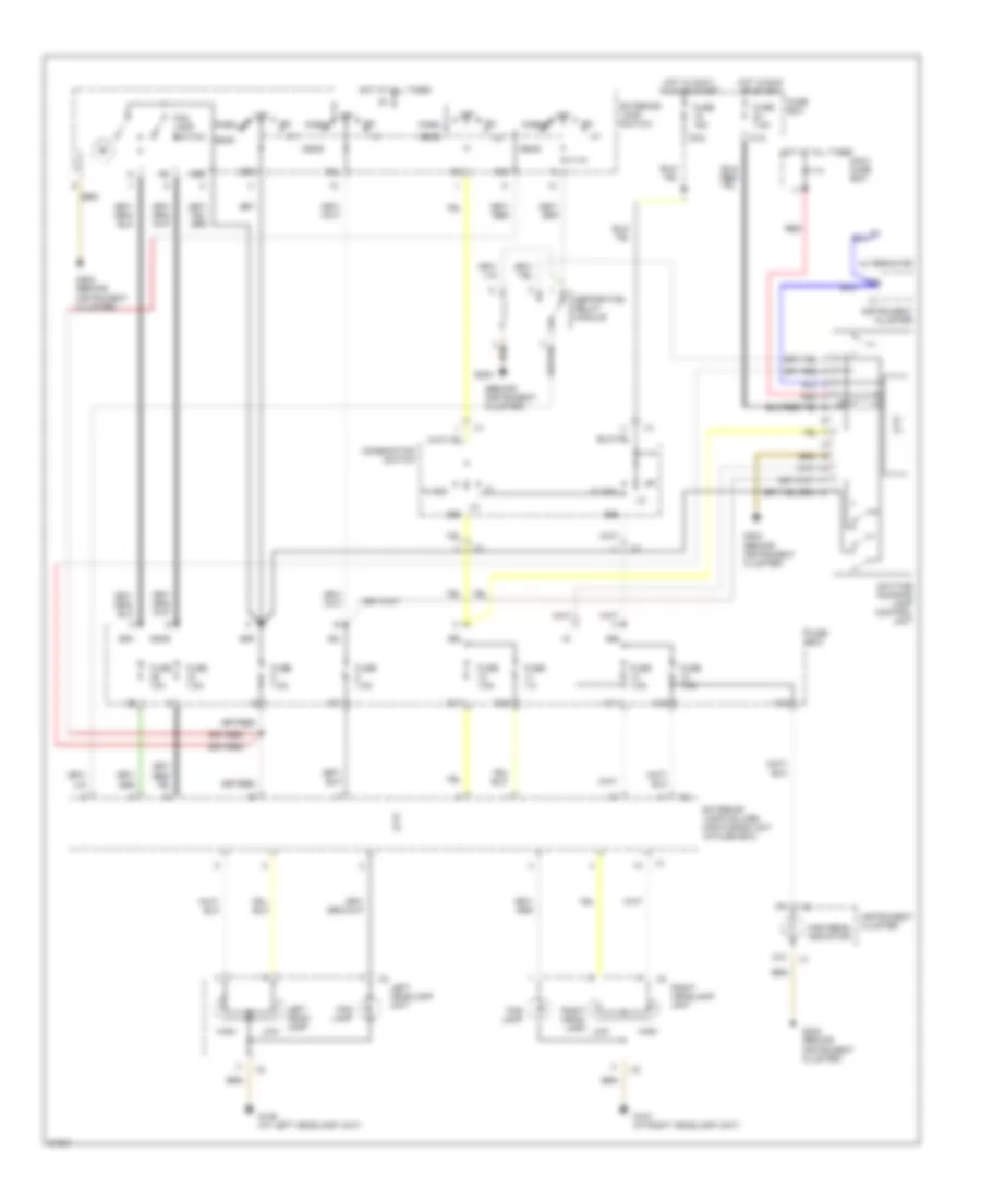
HEADLIGHTS Headlamps Wiring Diagram, with DRL for Mercedes-Benz S320 1994 List of elements for Headlamps Wiring Diagram, with DRL for Mercedes-Benz S320 1994: 53 (behind instrument cluster) 12/1 12/2 14/1 14/2 14/3 20/2 31/2 5/1 56a 56b 58l 58n 58ns 58r A10 A15 Alternator Combination switch Daytime running lamp control unit Exterior lamp failure monitoring unit (in fuse box) Exterior lamp switch Flash Fog lamp Fog lamp switch Fuse 10a Fuse 15a Fuse 7.5 Fuse 7.5a Fuse box G106 (at left headlamp unit) G107 (at right headlamp unit) G200 G202 (behind instrument cluster) Head High High beam indicator Hot at all times Hot in accy, run or start Hot in run or start Instrument cluster K30 Left head- lamp Left headlamp unit Low Maxi- fuse box Nse Off Park Red Right head- lamp Right headlamp unit Separation relay module Headlamps Wiring Diagram, without DRL for Mercedes-Benz S320 1994 List of elements for Headlamps Wiring Diagram, without DRL for Mercedes-Benz S320 1994: 42 12/1 12/2 14/1 14/2 14/3 20/2 5/1 56a 56b 58l 58n 58ns 58r A10 Combination switch Exterior lamp failure monitoring unit (in fuse box) Exterior lamp switch Flash Fog lamp Fog lamp switch Fuse 10a Fuse 15a Fuse 7.5 Fuse 7.5a Fuse box G106 (at left headlamp unit) G107 (at right headlamp unit) G202 (behind instrument cluster) Head High High beam indicator Hot at all times Hot in accy, run or start Instrument cluster Left head- lamp Left headlamp unit Low Nse Off Park Right head- lamp Right headlamp unit
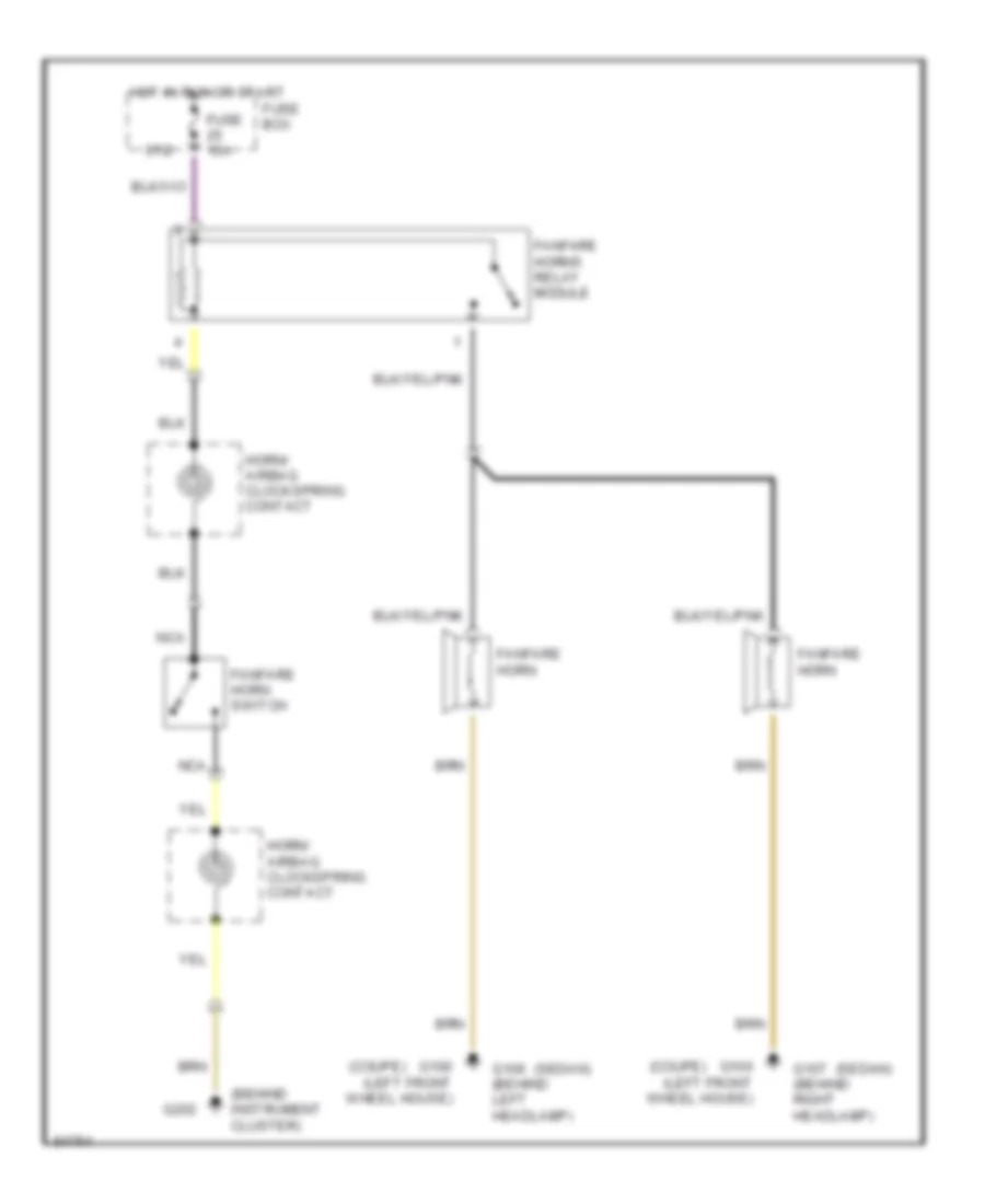
HORN Horn Wiring Diagram for Mercedes-Benz S320 1994 List of elements for Horn Wiring Diagram for Mercedes-Benz S320 1994: 16 (behind instrument cluster) (coupe) (sedan) 37/2 Fanfare horn Fanfare horn switch Fanfare horns relay module Fuse 15a Fuse box G100 (left front wheel house) G106 (behind left headlamp) G107 (behind right headlamp) G202 Horn/ airbag clockspring contact Hot in run or start Nca
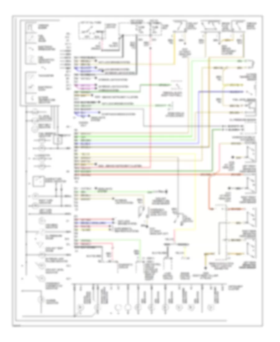
INSTRUMENT CLUSTER Instrument Cluster Wiring Diagram for Mercedes-Benz S320 1994 List of elements for Instrument Cluster Wiring Diagram for Mercedes-Benz S320 1994: 94 (ads i) (ads ii) (behind instrument cluster) 22/3 36/2 A10 A11 A12 A13 A14 A15 Acc Ads control module (in module box, right rear of engine compt) Anti-lock brakes system Audible turn signal indicator B10 B11 B12 B13 B14 B15 Base module (in module box) Brake fluid level switch Brake pad wear indicator Canada only Charge indicator Check engine indicator Combination relay (in fuse box) Coolant level indicator Coolant level switch Coolant temp gauge Coolant temperature gauge sensor D10 Diagnostic module Electronic clock Electronic speedometer Engine control module Exterior lamp failure indicator Exterior lights system Fuel consumption indicator Fuel level gauge Fuel level sensor Fuel reserve indicator Fuse 20a Fuse 7.5a Fuse box G106 (at left headlamp unit) G107 (at right headlamp unit) G202 G202 (behind instrument cluster) G405 (right rear taillamp, in trunk) Headlights system High beam indicator Hot at all times Hot in run or start Ignition switch Illumination Indicator & park brake brake fluid Indicator abs Indicator ads Indicator asr Indicator asr warning Indicator srs Instrument cluster Interior lights system Left front brake pad wear sensor Left rear brake pad brake pad wear sensor wear sensor Left turn indicator Lh-sfi control module Off Oil level indicator Oil level switch Oil pressure gauge Oil pressure sensor Outside temperature indicator Outside temperature sensor Parking brake switch Rear axle multiple circuit junction connector Rheostat Right front brake pad wear sensor Right rear brake pad wear sensor Right turn indicator Run S320 S420/s500 Seat belt indicator Start Starting/charging system Tachometer Terminal block (right footwell) Warning buzzer Warning system Windshield washer fluid indicator Windshield washer fluid level switch
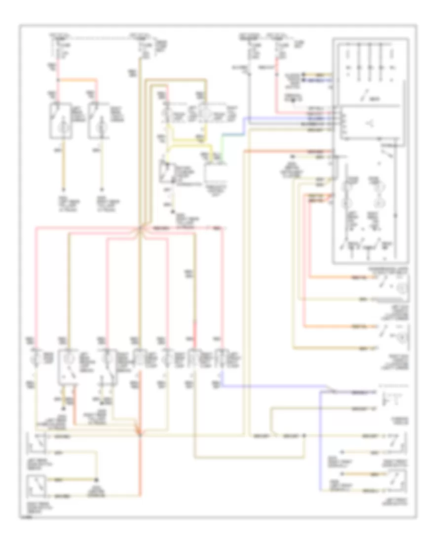
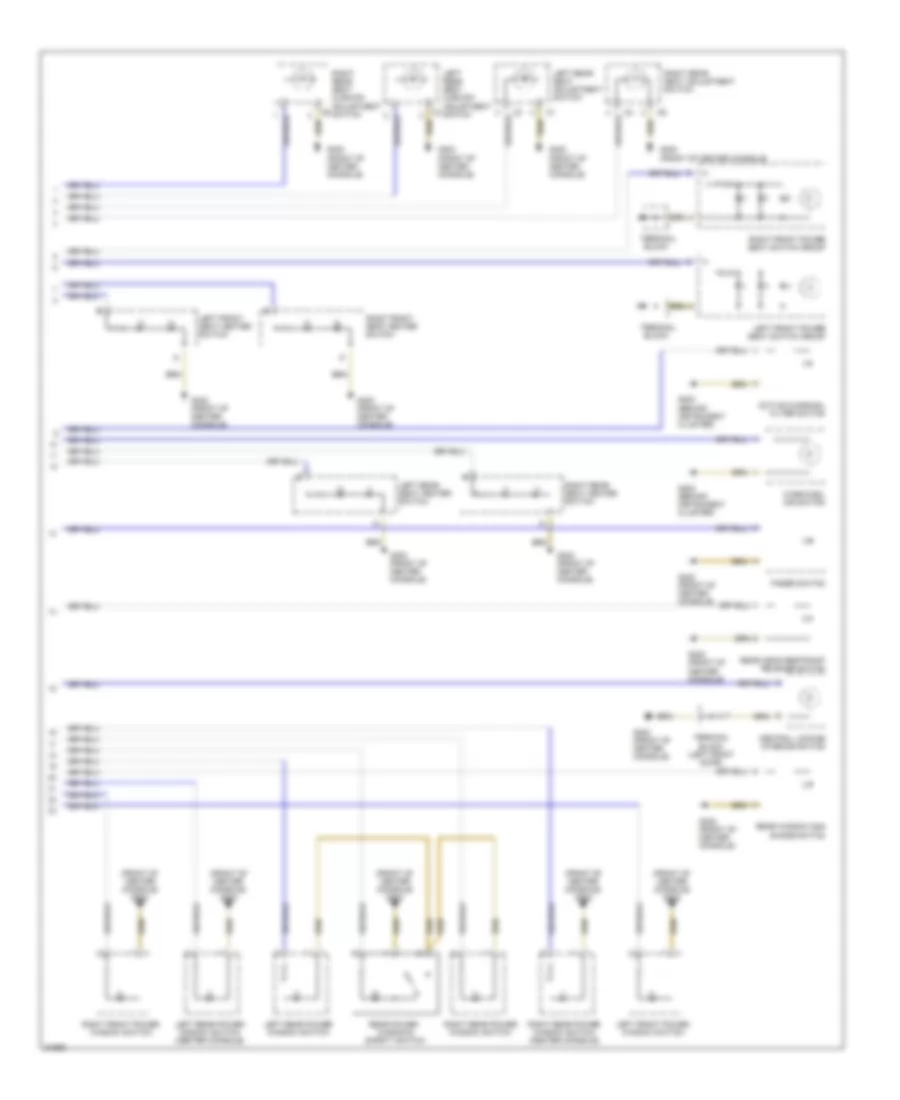
INTERIOR LIGHTS Courtesy Lamps Wiring Diagram for Mercedes-Benz S320 1994 List of elements for Courtesy Lamps Wiring Diagram for Mercedes-Benz S320 1994: 46 Dome Dome lamp Dome/reading lamps w/ shut off delay Door Fuse 20a 22/3 Fuse 20a 32/2 Fuse 7.5a Fuse 7.5a 36/2 Fuse box G202 (behind instrument cluster) G302 (center console) G309 (left front door sill) G316 (right front door sill) G402 (left rear wheelhousing, in trunk) G404 (left rear taillamp, in trunk) G405 (right rear taillamp, in trunk) Hot at all times Hot in run or start Left front door switch Left front exit lamp Left read- ing lamp Left rear door switch (sedan) Left rear exit lamp Left rear reading lamp (sedan) Left rear vanity mirror Left sun visor w/ illuminated vanity mirror Left tail- lamp unit Pneumatic control unit Read- ing Rear dome lamp Rear fuse box Red Right front door switch Right front exit lamp Right read- ing lamp Right rear door switch (sedan) Right rear exit lamp Right rear reading lamp (sedan) Right rear vanity mirror Right sun visor w/ illuminated vanity mirror Right tail- lamp unit Rotary tumbler/ trunk lid microswitch Sliding/ popup roof switch Terminal block x6 Trunk lamp Warning module Instrument Illumination Wiring Diagram (1 of 2) for Mercedes-Benz S320 1994 List of elements for Instrument Illumination Wiring Diagram (1 of 2) for Mercedes-Benz S320 1994: 44 (behind (behind instrument cluster) g202 (behind right rear seat) g303 (front of center console) (front of center console) g302 58r A/c pushbutton control module Air distribution switch Center air outlet controls Cluster) g202 Comfort/ sport switch Dome lamp w/ shut- off & reading lamp Exterior lamp switch Exterior lights system Front cigar lighter w/ ashtray illumination Fuse 7.5a Fuse box G202 (behind instrument cluster) G302 G302 (center console) G302 (front of center console) Glove compartment lock Head Hot at all times Hot in off & accy Instrument Instrument cluster K30 Left rear cigar lighter (sedan) Nca Off Outside rearview mirror switch P30 Park Radio Rear air outlet Rear cigar lighter (coupe) Rear window defroster switch Rheostat Right rear cigar lighter (sedan) Seat belt extender switch Terminal block x6 (left side of dash) Transmission selector lever Warning module Instrument Illumination Wiring Diagram (2 of 2) for Mercedes-Benz S320 1994 List of elements for Instrument Illumination Wiring Diagram (2 of 2) for Mercedes-Benz S320 1994: 30 (front of center console) g302 Active charcoal filter switch Block Central locking interior switch Fader switch G202 (behind instrument cluster) G302 (front of center console) G302 (front of center console) Left front power seat switch group Left front power window switch Left front seat heater switch Left rear power window switch Left rear power window switch (center console) Left rear seat adjustment switch Left rear seat cushion adjustment c3 switch Left rear seat heater switch Rear head restraint release switch Rear power windows safety switch Rear window sun shade switch Right front power seat switch group Right front power window switch Right front seat heater switch Right rear power window switch Right rear power window switch (center console) Right rear seat cushion adjustment c6 switch Right rear seat adjustment switch Right rear seat heater switch Terminal Terminal block (left front door) Warm/cool air switch
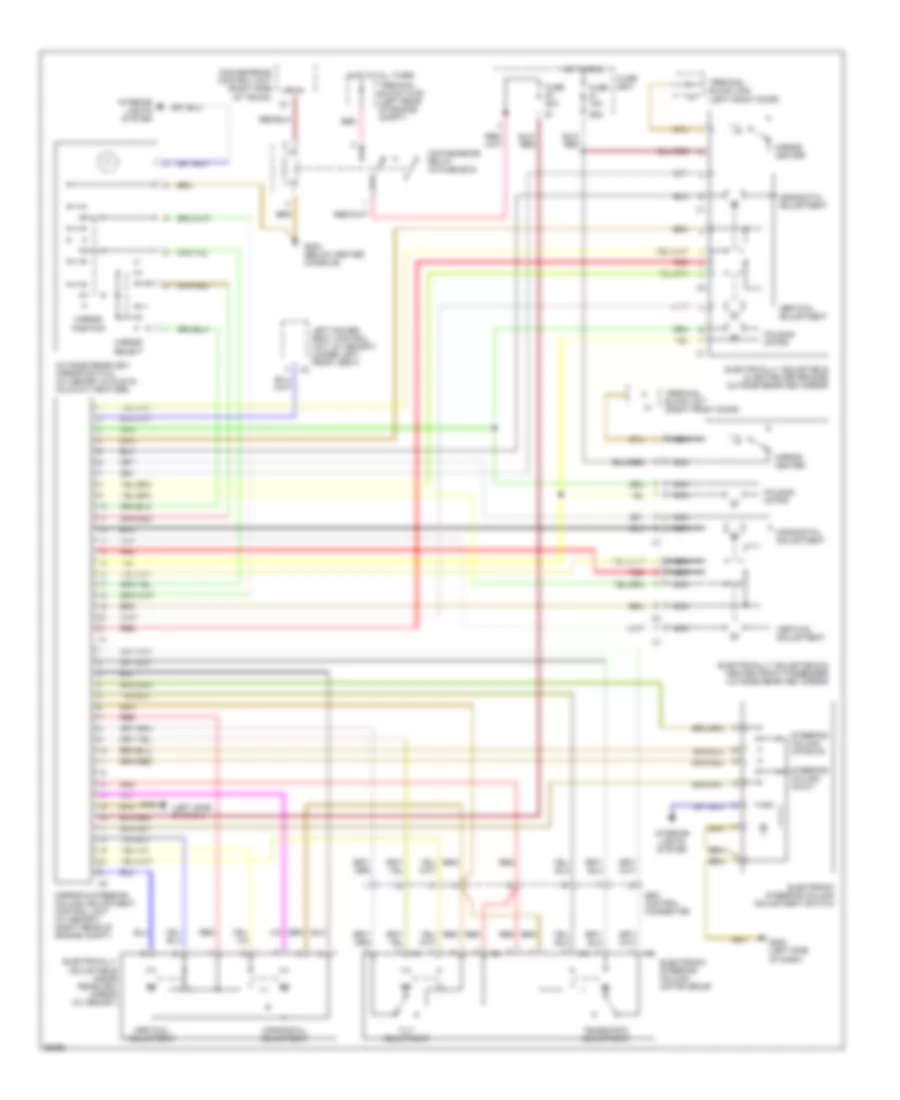
MEMORY SYSTEMS Memory Mirrors & Telescopic Steering Wiring Diagram for Mercedes-Benz S320 1994 List of elements for Memory Mirrors & Telescopic Steering Wiring Diagram for Mercedes-Benz S320 1994: 39 (left side of dash) 15r/30 29/2 Bll/red Convenience control unit (right side of trunk) Convenience relay (in fuse box) Electrically adjustable & heated driver-side outside rearview mirror Electrically adjustable & heated front passenger outside rearview mirror Electrically adjustable inside rearview mirror (w/ memory) Electronic steering column adjustment switch Electronic steering column motor group Esc control connector Folding motor Fuse 15a Fuse 20a Fuse box G202 G202 (left side of dash) G302 (below center console) Horizontal adjustment Hot at all times Hot in run Interior lights system Left power seat control unit (w/ memory) (under left front seat) Mirror & steering column adjustment control unit (w/ memory) (right rear of engine compt) Mirror heater Mirror position Mirror select Nca Outside rearview mirror switch (w/ memory & fold-in/ fold-out feature) Red Steering column in/out Steering column up/down Telescopic adjustment Terminal block x4/20 (left rear of engine compt) Terminal block x8/6 (left front door) Terminal block x8/7 (right front door) Tilt adjustment Vertical adjustment Memory Seat Wiring Diagram for Mercedes-Benz S320 1994 List of elements for Memory Seat Wiring Diagram for Mercedes-Benz S320 1994: 37 * ** * left front ** right front (left front door sill) (right front door sill) * ** 15r/30 65/1 68/2 78/1 82/2 78/2 82/1 Backrest Convenience control unit (right side of trunk) Convenience relay (in fuse box) Fuse * ** 30a Fuse 20a Fuse box G302 (below center console) G309 * ** G316 Head restraint up/down Hot at all times Interior lights system Left front only Left or right front door plug connector Left or right front power seat motor group with memory Left or right front power seat switch Left or right front seat memory control unit (under seat) Memory Mirror and steering column adjust control unit (right side of i/p) Pnk Position Red Seat cushion height Seat forward/ backward Seat fwd/back Seat height front Seat height rear Terminal block x4/20 (left rear of engine compt) V * **
PASSIVE RESTRAINTS Seat Belt Extender Wiring Diagram for Mercedes-Benz S320 1994 List of elements for Seat Belt Extender Wiring Diagram for Mercedes-Benz S320 1994: 31 (front of console) g302 74/2 Combination relay (in fuse box) Fuse 20a Fuse 7.5a Fuse box G302 (front of console) G309 (left front door sill) G316 (right front door sill) Hot at all times Hot in acc, run or start Interior lights Left door switch Left front seat belt adjustment solenoid Left front seat belt buckle switch Left rear seat belt adjustment solenoid Left rear seat belt buckle switch Left seat belt extender Nca Pnk Rear fuse box Right door switch Right front seat belt adjustment solenoid Right front seat belt buckle switch Right rear seat belt adjustment solenoid Right rear seat belt buckle switch Right seat belt extender Seat belt extender switch Seat belt extender system control module (behind right rear seat) Warning system Warning systems
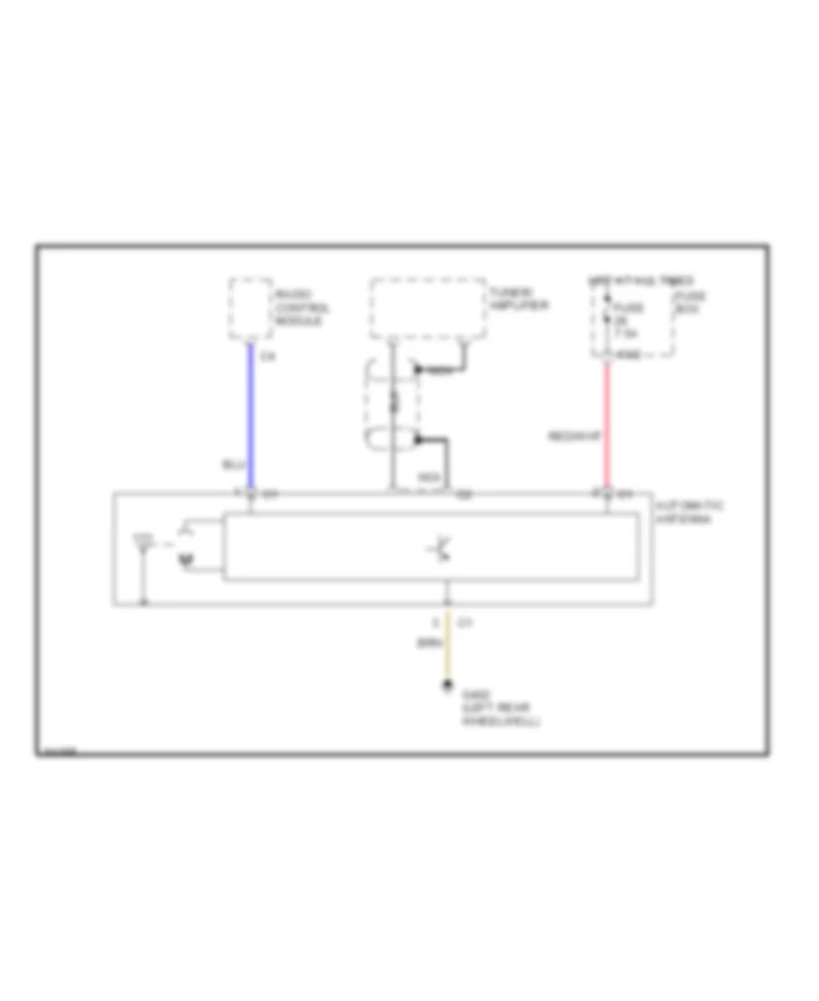
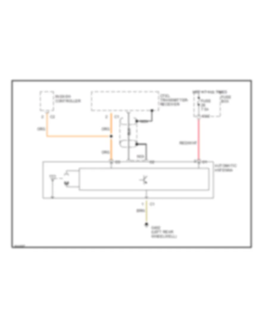
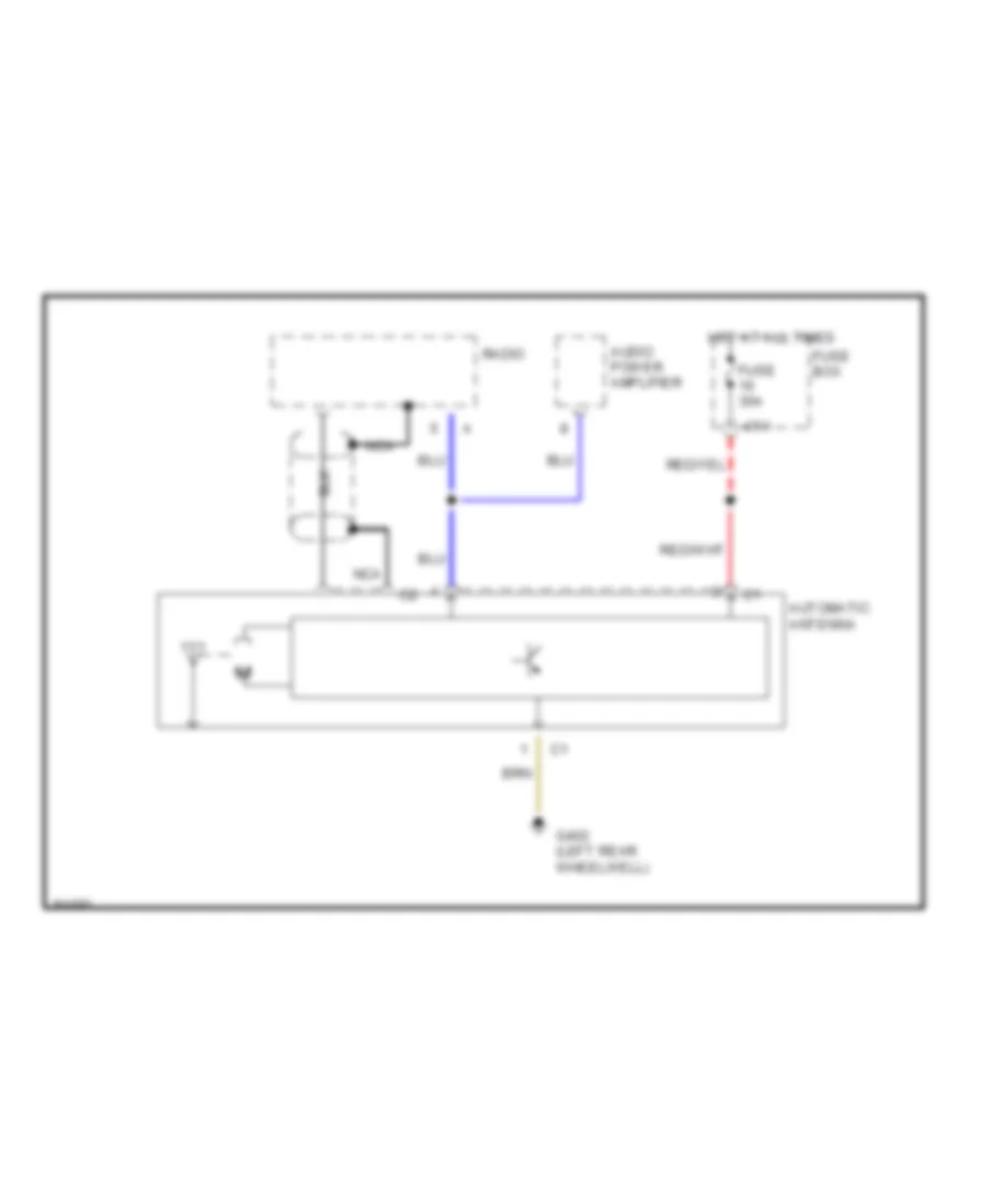
POWER ANTENNA Power Antenna Wiring Diagram, with Bose Audio for Mercedes-Benz S320 1994 List of elements for Power Antenna Wiring Diagram, with Bose Audio for Mercedes-Benz S320 1994: 9 63/2 Automatic antenna Fuse 7.5a Fuse box G402 (left rear wheelwell) Hot at all times Nca Radio control module Tuner/ amplifier Power Antenna Wiring Diagram, with Cellular Telephone for Mercedes-Benz S320 1994 List of elements for Power Antenna Wiring Diagram, with Cellular Telephone for Mercedes-Benz S320 1994: 9 63/2 Automatic antenna Ctel transmitter- receiver Fuse 7.5a Fuse box G402 (left rear wheelwell) Hot at all times In-dash controller Nca Power Antenna Wiring Diagram, without Cellular Telephone or Bose Audio for Mercedes-Benz S320 1994 List of elements for Power Antenna Wiring Diagram, without Cellular Telephone or Bose Audio for Mercedes-Benz S320 1994: 9 47/1 Audio power amplifier Automatic antenna Fuse 30a Fuse box G402 (left rear wheelwell) Hot at all times Nca Radio
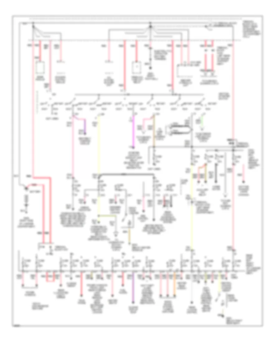
POWER DISTRIBUTION Power Distribution Wiring Diagram (1 of 2) for Mercedes-Benz S320 1994 List of elements for Power Distribution Wiring Diagram (1 of 2) for Mercedes-Benz S320 1994: 104 (battery harness) (canada) (left (left rear (left rear of engine (not used) (right front (right rear (w/ asr) (w/o asr) *30a-w/ convenience feature 15c 15r 15x 15z 17/1 17/2 20/1 20/2 30z 32/1 32/2 7.5a 71/2 74/1 74/2 A/c system blower unit Abs/asr hydraulic unit Accy Airbag indicator Anti- theft alarm system, infrared remote control, rear heated seats Anti-theft alarm system, infrared remote control, rear head restraints Auxiliary fan relay Base module Battery Central locking, closing assist Closing assist Combination relay, front heated seats, rear heated seats, seat belt comfort feature, seat belt warning module Compart- Compartment) Compartment, on component Daytime running lamps Electrolytic capacitor Ets/sps control module Footwell) Front cigar lighter Fuel pumps Fuse Fuse 10a Fuse 15a Fuse 20a Fuse 25a Fuse 25a * Fuse 30a Fuse 40a Fuse 7.5a Fuse box G203 (right G302 (below center console) G303 (below right rear seat) G405 (right side Heated rear window Heated seats Heated seats, defogger, relay module, seat belt extender Ignition/ starter switch Infrared central locking Maxi- fuse box Ment) Nca Of engine Of engine compart- Of luggage Off Power windows Power windows, trunk lamp, rear interior lamp, rear reading lamp, rear entrance/ exit lamp, central locking Preglow time-limit relay Radio sound system: tuner & amplifier Rear cigar lighter Rear climate control Rear fuse box Rear illuminated vanity mirror Rear of engine Rear window sunshield, convenience system Red Red red Red/ red Run Seatbelt warning module Sliding/ pop-up roof Srs control unit Start Starter lock-out/ back-up lamp relay selector lever position recognition Tele- phone Terminal block x/4 Terminal block x4/10 Terminal block x4/20 Terminal block x4/5 To combination switch (diagram 2 of 2) To exterior lamp switch (diagram 2 of 2) To fuse box (diagram 2 of 2) To terminal block (diagram 2 of 2) Wall) Wiper motor Wiper relay, washer pump, combination relay, rear window defogger switch Power Distribution Wiring Diagram (2 of 2) for Mercedes-Benz S320 1994 List of elements for Power Distribution Wiring Diagram (2 of 2) for Mercedes-Benz S320 1994: 131 (bridge) (canada) (not used) (right rear 12/1 12/2 14/1 14/2 14/3 15r/30 22/1 22/2 22/3 24/3 28/1 28/2 28/3 29/2 3/1 31/2 36/1 36/2 37/1 37/2 5/1 5/2 56a 56b 58l 58n 58ns 58r 63/2 65/1 68/2 69/1 69/2 7/3 78/1 78/2 82/1 82/2 9/1 Air conditioning, auxiliary coolant pump control relay module Alternator Ata control unit Automatic climate control, a/c compressor, base module kickdown switch Base module Base module, purge control valve, instrument cluster, exterior lamp failure monitoring module, interior lights, electromagnetic air injection pump clutch, stop lamp switch, seat belt warning module, daytime running lights, engine controls Combination switch Compartment) Compartment, on component Convenience relay Daytime running lamps Electronic antenna Engine controls Exterior lamp switch Flash -to- pass Fog lamp switch From fuse 15 (diagram 1 of 2) From ignition/ starter switch (diagram 1 of 2) From ignition/starter switch (diagram 1 of 2) From maxi-fuse box (diagram 1 of 2) From terminal block a (diagram 1 of 2) From terminal block x4/10 (diagram 1 of 2) Front fog lamps Front heated seats Fuse 10a Fuse 11 7.5a Fuse 12 7.5a Fuse 13 7.5a Fuse 14 7.5a Fuse 17 20a Fuse 18 15a Fuse 19 7.5a Fuse 20 10a Fuse 21 15a Fuse 23 7.5a Fuse 24 7.5a Fuse 25 15a Fuse 27 25a Fuse 28 7.5a Fuse 29 20a Fuse 30 20a Fuse 31 30a Fuse 32 30a Fuse 33 20a Fuse 36 10a Fuse 37 30a Fuse 38 30a Fuse 40 30a Fuse 41 30a Fuse 7 10a Fuse 7.5a Fuse 8 7.5a Fuse 9 7.5a Fuse box Fuse box (left rear of engine Head Headlamp cleaning system Heated windshield washer nozzles, power/heated mirrors, transmission oil cooler Ignition coil Ignition shut-off relay, radio, steering angle sensor, generic scan tool connector, instrument cluster, make-up mirror illumination, turn signal/ hazard flasher switch Injectors, instrument cluster, cruise control switch, glow/starter switch, stop lamp switch, center high mounted stop lamp Instrument cluster K30 Left front power seat Left high beam headlamp, high beam indicator Left low beam headlamp Left standing lamp, left taillamp, left side-marker lamps Left/right seat memory, driver memory steering column adjust Nca Nse Of engine Off P30 Park Rear fog lamps Rear power bench seat w/ passenger seat adjustment or left rear power seat w/ front passenger seat adjustment Rear power seat, trunk lamp, right rear head restraint Red Right front power seat Right high beam headlamp Right low beam headlamp Right standing lamp, right taillamp, right side marker lamps, license plate illumination, engine speed increase diode matrix Standing Starter Terminal block x4/10 Turn signal/hazard warning flasher relay, fan relay module, starter lock-out/ backup lamp switch, shift valve/solenoid valve Wall) Warning buzzer, exterior lamp failure monitoring unit
POWER DOOR LOCKS Central Locking Wiring Diagram for Mercedes-Benz S320 1994 List of elements for Central Locking Wiring Diagram for Mercedes-Benz S320 1994: 45 (right side of engine compt) 32/1 32/2 37/1 A/c system Acc Anti-theft alarm control unit (right side of trunk) B16 B20 Cf control unit (right side of trunk) Cl trunk lid switch Exterior lights system Fuse 15a Fuse 20a Fuse box G202 (behind instrument cluster) G302 (center console) G303 (below right rear seat) G316 (inside right rocker panel) G405 (right rear taillamp, in trunk) Hot at all times Hot in run or start Ignition/ starter switch Interior cl switch Interior lights system Left front door lock switch Left rear door switch Nca Off Pse control module Rear fuse box Rhr release switch Right front door lock switch Right front door switch Right rear door switch Rotary tumbler/ trunk lid microswitch Run Start Starter lock-out/ backup lamp switch Terminal block x46/5 (right side of i/p) Terminal block x8/6 (left front door) Terminal block x8/7 (right front door) Test connection for diagnosis Trunk lid lock switch Trunk lid remote control valve (1995) Infrared Central Locking Wiring Diagram for Mercedes-Benz S320 1994 List of elements for Infrared Central Locking Wiring Diagram for Mercedes-Benz S320 1994: 41 Acc Anti-theft alarm control unit (right side of trunk) B16 B20 Convenience control unit (right side of trunk) Fuse 25a Fuse 7.5a G202 (behind instrument cluster) G402 (left rear wheelhousing, in trunk) G405 (right rear taillamp, in trunk) Hot at all times Hot in run or start Ignition/ starter switch Infrared remote control unit (right side of trunk) Interior lights system Left front door actuator Left front door closing assist microswitch Left front door ir receiver Left front door lock switch Left front door rotary tumbler microswitch Luggage compartment fuse box Nca Off Only Pse control module Red Right front door closing assist microswitch Right front door ir receiver Right front door lock switch Right front door rotary tumbler microswitch Right rear door closing assist microswitch Right rear door rotary tumbler microswitch Rotary tumbler/ trunk lid microswitch Run Start Starter lock-out relay module Terminal block x8/6 (left front door) Terminal block x8/7 (right front door) Test connection for diagnosis (right side of engine compt) Trunk lid ir receiver Trunk lid lock switch Remote/Central Locking Wiring Diagram for Mercedes-Benz S320 1994 List of elements for Remote/Central Locking Wiring Diagram for Mercedes-Benz S320 1994: 41 Acc Anti-theft alarm control unit (right side of trunk) B16 B20 Convenience control unit (right side of trunk) Fuse 25a Fuse 7.5a G202 (behind instrument cluster) G402 (left rear wheelhousing, in trunk) G405 (right rear taillamp, in trunk) Hot at all times Hot in run or start Ignition/ starter switch Infrared remote control unit (right side of trunk) Interior lights system Left front door actuator Left front door closing assist microswitch Left front door ir receiver Left front door lock switch Left front door rotary tumbler microswitch Luggage compartment fuse box Nca Off Only Pse control module Red Right front door closing assist microswitch Right front door ir receiver Right front door lock switch Right front door rotary tumbler microswitch Right rear door closing assist microswitch Right rear door rotary tumbler microswitch Rotary tumbler/ trunk lid microswitch Run Start Starter lock-out relay module Terminal block x8/6 (left front door) Terminal block x8/7 (right front door) Test connection for diagnosis (right side of engine compt) Trunk lid ir receiver Trunk lid lock switch
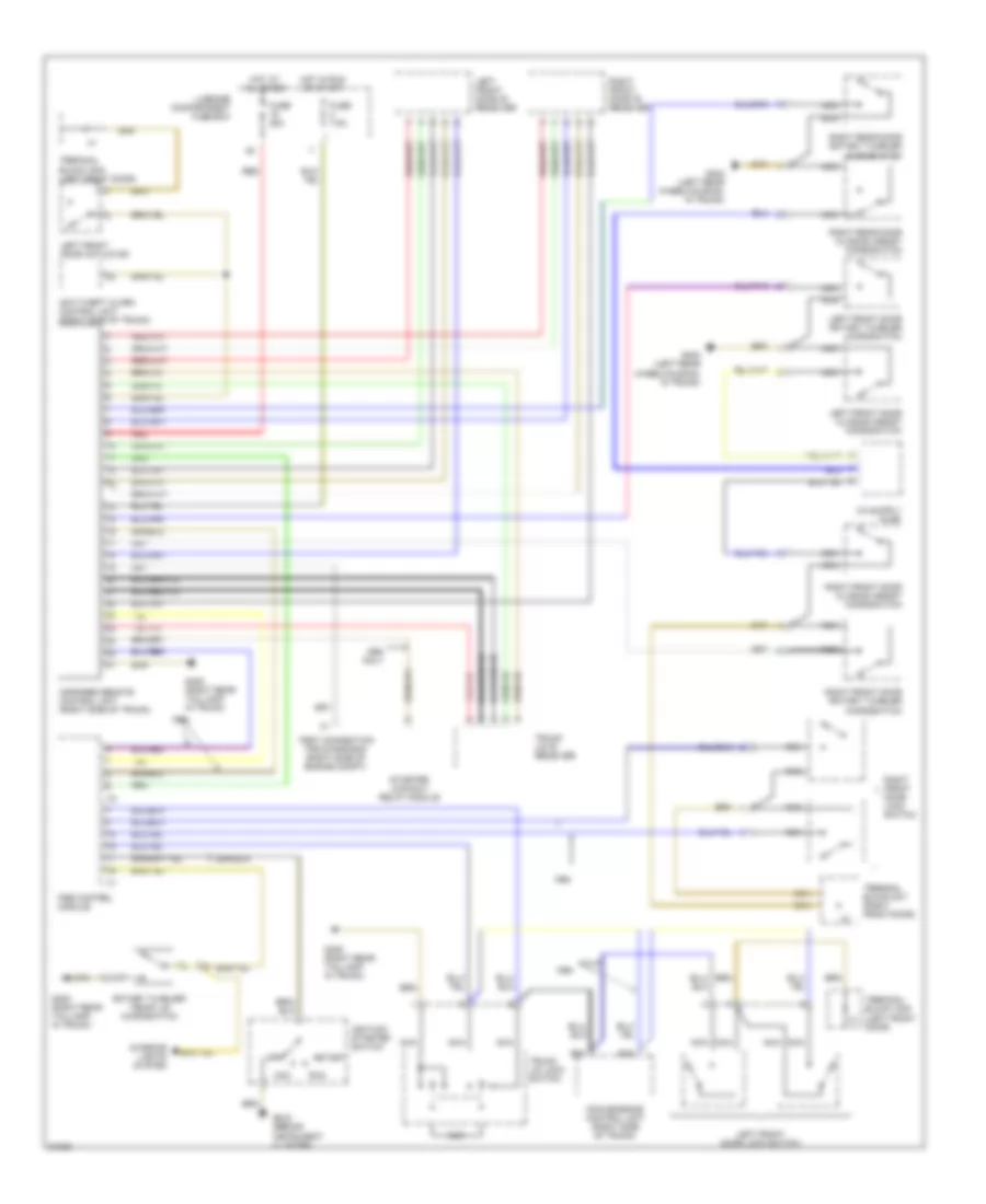
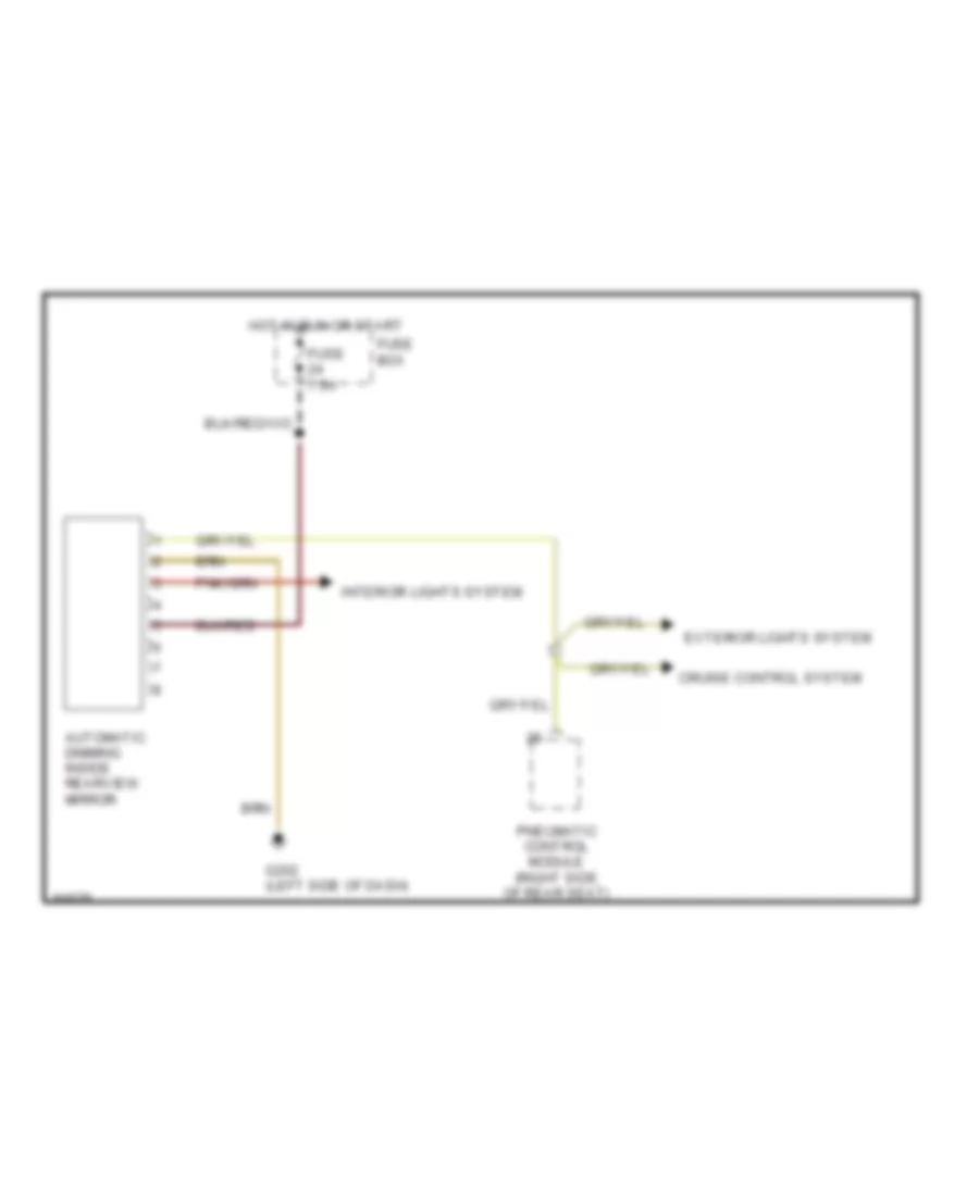
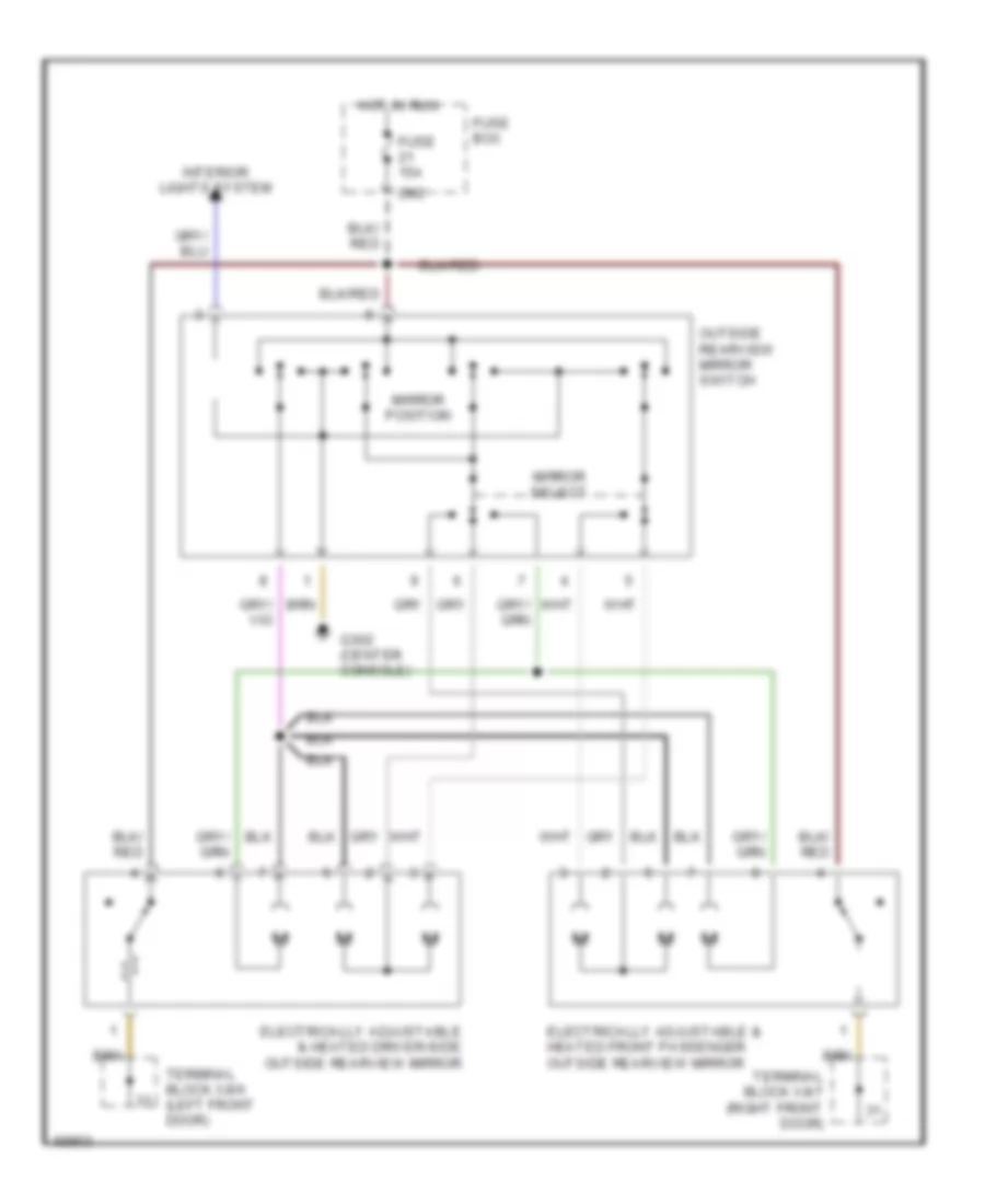
POWER MIRRORS Automatic Day/Night Mirror Wiring Diagram for Mercedes-Benz S320 1994 List of elements for Automatic Day/Night Mirror Wiring Diagram for Mercedes-Benz S320 1994: 9 Automatic dimming inside rearview mirror Cruise control system Exterior lights system Fuse 7.5a Fuse box G202 (left side of dash) Hot in run or start Interior lights system Pneumatic control module (right side of rear seat) Power Mirror Wiring Diagram for Mercedes-Benz S320 1994 List of elements for Power Mirror Wiring Diagram for Mercedes-Benz S320 1994: 13 29/2 Electrically adjustable & heated driver-side outside rearview mirror Electrically adjustable & heated front passenger outside rearview mirror Fuse 15a Fuse box G302 (center console) Hot in run Interior lights system Mirror position Mirror select Outside rearview mirror switch Terminal block x8/6 (left front door) Terminal block x8/7 (right front door)
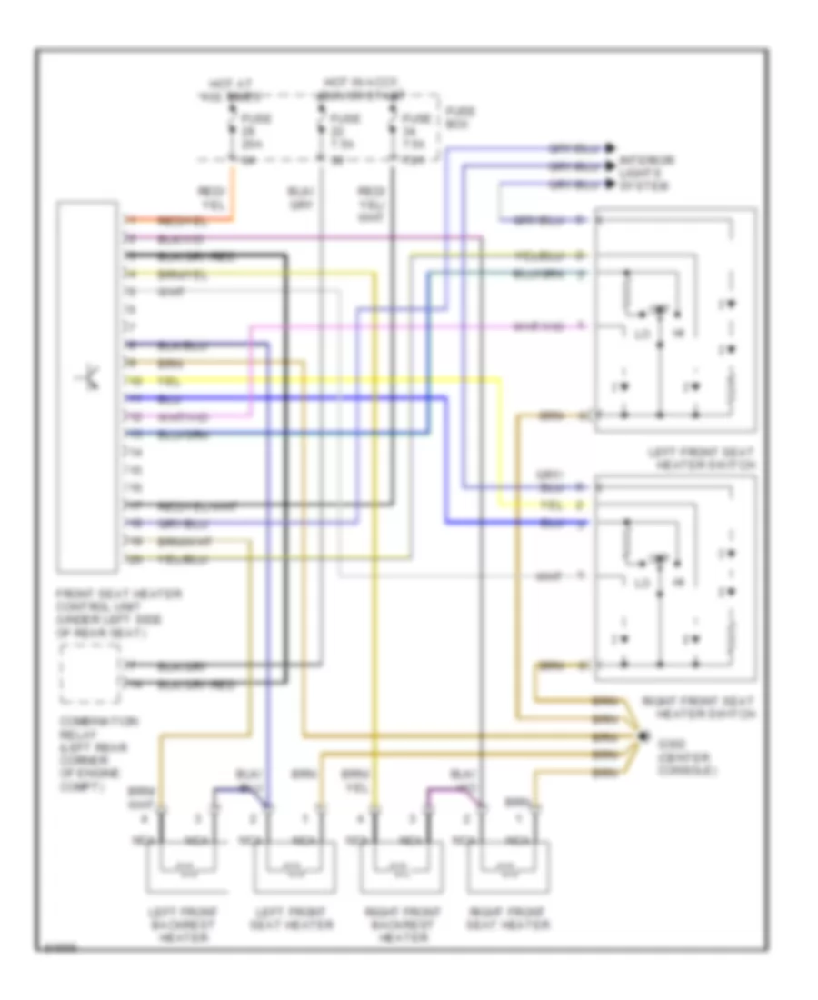
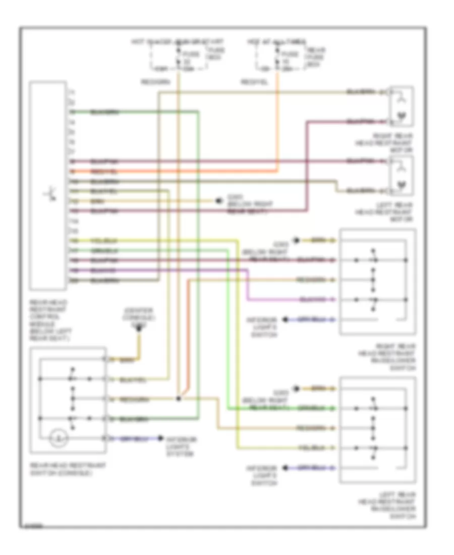
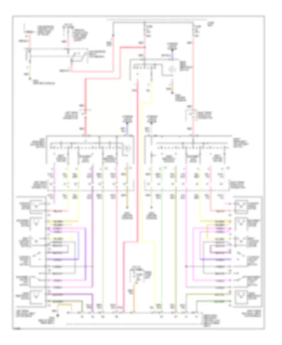
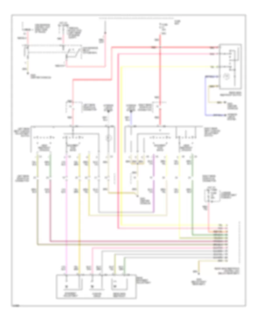
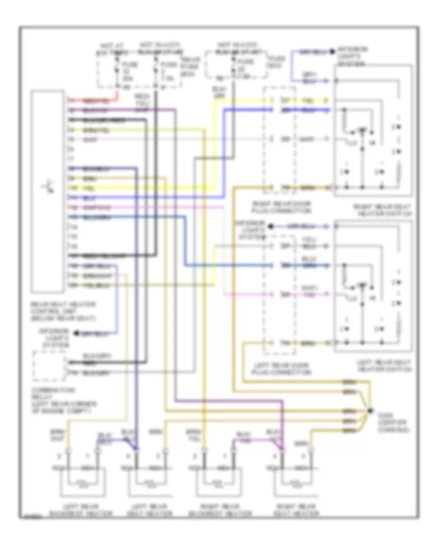
POWER SEATS Front Seat Heater Wiring Diagram for Mercedes-Benz S320 1994 List of elements for Front Seat Heater Wiring Diagram for Mercedes-Benz S320 1994: 18 73/1 Combination relay (left rear corner of engine compt) Front seat heater control unit (under left side of rear seat) Fuse 20a Fuse 7.5a Fuse box G302 (center console) Hot at all times Hot in accy, run or start Interior lights system Left front backrest heater Left front seat heater Left front seat heater switch Nca Off Right front backrest heater Right front seat heater Right front seat heater switch Rear Head Restraint Wiring Diagram, Coupe for Mercedes-Benz S320 1994 List of elements for Rear Head Restraint Wiring Diagram, Coupe for Mercedes-Benz S320 1994: 17 (center console) g302 69/1 Fuse 25a Fuse 30a Fuse box G303 (below right rear seat) Hot at all times Hot in accy, run or start Interior lights switch Interior lights system Left rear head restraint motor Left rear head restraint raise/lower switch Rear fuse box Rear head restraint control module (below left rear seat) Rear head restraint switch (console) Right rear head restraint motor Right rear head restraint raise/lower switch Rear Power Seat Wiring Diagram, with Four Place Seating for Mercedes-Benz S320 1994 List of elements for Rear Power Seat Wiring Diagram, with Four Place Seating for Mercedes-Benz S320 1994: 44 15r/30 69/1 69/2 Adjust Adjust motor Angle motor Backrest Backrest adjust limit switch Backrest adjust motor Backrest fwd/ bkwd Convenience control unit (right side of trunk) Convenience relay (in fuse box) Cushion Cushion adjust limit switch Cushion angle motor Fuse 25a Fuse 30a Fuse box G302 (center console) G303 (below right rear seat) Head Head restraint motor Head restraint up/down Hot at all times Interior lights system Left rear door plug connection Left rear individual seat motor group Left rear seat adjustment switch Limit Motor Pnk Rear fuse box Rear head restraint control unit (below rear seat) Rear head restraint switch Red Restraint Right rear door plug connection Right rear individual seat motor group Right rear seat adjustment switch Seat Seat cushion adjust motor Seat cushion incline Switch Terminal block x4/20 (left rear of engine compt) Rear Power Seat Wiring Diagram, with Rear Bench Seat for Mercedes-Benz S320 1994 List of elements for Rear Power Seat Wiring Diagram, with Rear Bench Seat for Mercedes-Benz S320 1994: 29 15r/30 69/2 Backrest adjustment Backrest fwd/ bkwd Convenience control unit (right side of trunk) Convenience relay (in fuse box) Cushion angle Fuse 25a Fuse 30a Fuse box G302 (center console) G303 (below right rear seat) Head restraint up/down Hot at all times Interior lights system Left rear door plug connection Left rear door plug connector Left rear seat cushion adjustment switch Luggage compartment fuse box Pnk Rear backrest adjustment Rear head restraint Rear head restraint control unit (below rear seat) Rear head restraint switch Red Right rear door plug connection Right rear door plug connector Right rear seat cushion adjustment switch Terminal block x4/20 (left rear of engine compt) Rear Seat Heater Wiring Diagram for Mercedes-Benz S320 1994 List of elements for Rear Seat Heater Wiring Diagram for Mercedes-Benz S320 1994: 20 Combination relay (left rear corner of engine compt) Fuse 20a Fuse 7.5a Fuse box G302 (center console) Hot at all times Hot in accy, run or start Interior lights system Left rear backrest heater Left rear door plug connection Left rear seat heater Left rear seat heater switch Nca Off Rear fuse box Rear seat heater control unit (below rear seat) Right rear backrest heater Right rear door plug connection Right rear seat heater Right rear seat heater switch
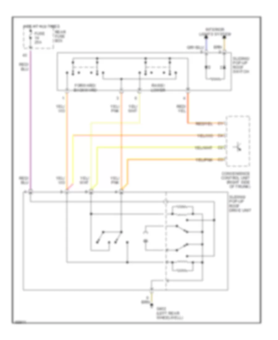
POWER TOP/SUNROOF Power Top/Sunroof Wiring Diagrams for Mercedes-Benz S320 1994 List of elements for Power Top/Sunroof Wiring Diagrams for Mercedes-Benz S320 1994: 10 Convenience control unit (right side of trunk) Forward/ backward Fuse 25a G402 (left rear wheelwell) Hot at all times Interior lights system Raise/ lower Rear fuse box Sliding/ pop-up roof drive unit Sliding/ pop-up roof switch
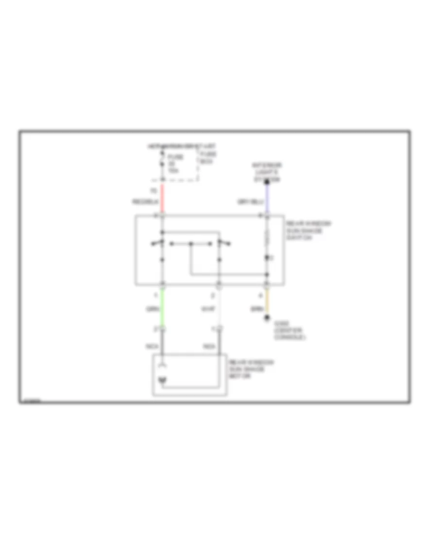
POWER WINDOWS Power Windows Wiring Diagram for Mercedes-Benz S320 1994 List of elements for Power Windows Wiring Diagram for Mercedes-Benz S320 1994: 48 A10 A11 A12 A13 A15 A16 A18 A19 A20 A21 B10 B11 B12 B13 B15 B17 B18 B21 Center console rear power windows safety switch Convenience control unit (right side of trunk) Data link connector (right rear corner of eng compt) Dn to Dn to limit Front center console left front power window switch Front center console left rear power window switch Front center console right rear power window switch Fuse 15a Fuse 20a Fuse 25a Fuse box G302 (center console) G405 (right rear tail- lamp, in trunk) Hot at all times Hot in acc, run & start Interior lights system Left front door switch Left front power window motor Left rear power window motor Left rear power window switch Limit Rear fuse box Right front door switch Right front power window motor Right front power window switch Right rear power window motor Right rear power window switch Up to Up to limit Rear Window Sun Shade Wiring Diagram for Mercedes-Benz S320 1994 List of elements for Rear Window Sun Shade Wiring Diagram for Mercedes-Benz S320 1994: 8 Fuse 15a Fuse box G302 (center console) Hot in run or start Interior lights system Nca Rear window sun shade motor Rear window sun shade switch
RADIO Radio Wiring Diagrams for Mercedes-Benz S320 1994 List of elements for Radio Wiring Diagrams for Mercedes-Benz S320 1994: 35 (1996-99) (1994-95) 1995-99 1996-99 Am rear window antenna amplifier Antenna Asr/sps control module or esp/sps/control module (right rear of engine compt) Center fill tweeter speaker Combination relay module Ctel transmitter/ receiver Fm bumper antenna amplifier Fuse 16 30a Fuse 22 7.5a Fuse box G302 (below center console) G402 (left rear wheelhouse) Hot at all times Hot in run or start Interior lights system Left front axle vss sensor Left front door speaker (coupe) Left front door speaker group Left rear door speaker (other) Left rear speaker group Left/right audio power amplifier (left side of trunk) Nca Power antenna system Radio Rear fuse box Right front door speaker (coupe) Right front door speaker group Right rear door speaker (other) Right rear speaker group Terminal block x46/5 W/ power antenna W/o power antenna
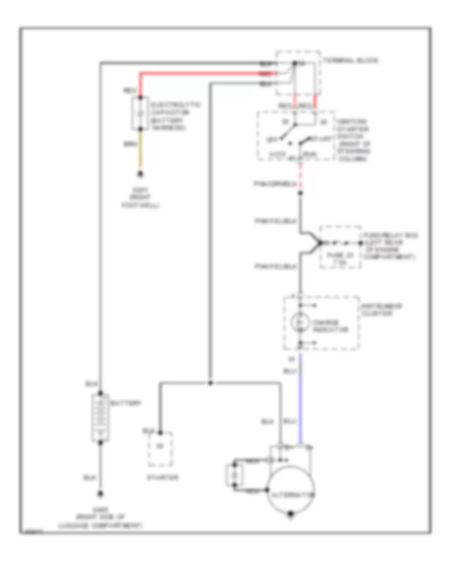
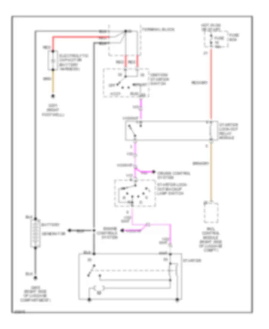
STARTING/CHARGING Charging Wiring Diagram for Mercedes-Benz S320 1994 List of elements for Charging Wiring Diagram for Mercedes-Benz S320 1994: 24 (battery harness) (left rear of engine (right of steering column) Accy Alternator Battery Charge indicator Compartment) Electrolytic capacitor Footwell) Fuse 23 7.5a Fuse/relay box G201 (right G405 (right side of Ignition/ starter switch Instrument cluster Luggage compartment) Nca Off Red Run Start Starter Terminal block Starting Wiring Diagram for Mercedes-Benz S320 1994 List of elements for Starting Wiring Diagram for Mercedes-Benz S320 1994: 23 (battery harness) Accy Battery Cruise control system Electrolytic capacitor Engine controls system Footwell) Fuse 10a Fuse box G201 (right G405 (right side of luggage compartment) Generator Hot in on or start Ignition/ starter switch Ircl control module (right side of luggage compt) Off Red Run Start Starter Starter lock- out/backup lamp switch Starter lock-out relay module Terminal block
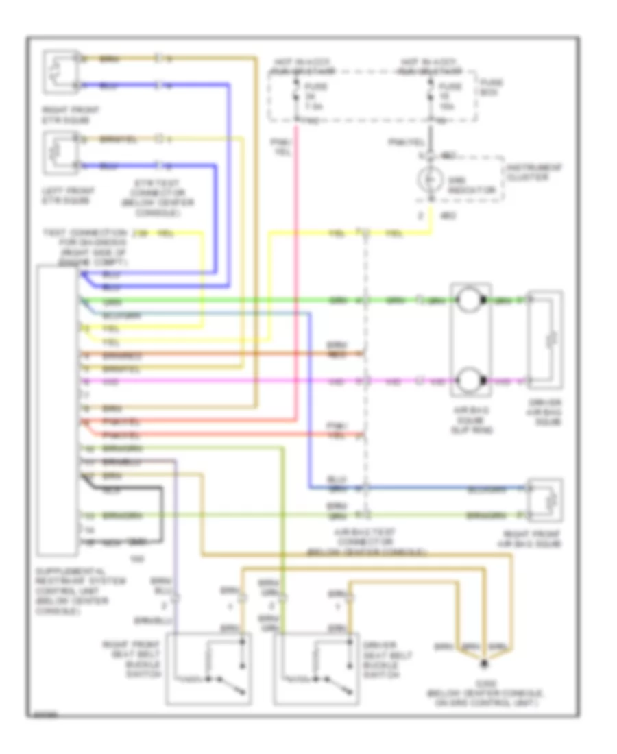
SUPPLEMENTAL RESTRAINTS Supplemental Restraint Wiring Diagram for Mercedes-Benz S320 1994 List of elements for Supplemental Restraint Wiring Diagram for Mercedes-Benz S320 1994: 21 4b2 71/2 Air bag squib slip ring Air bag test connector (below center console) Driver air bag squib Driver seat belt buckle switch Etr test connector (below center console) Fuse 15a Fuse 7.5a Fuse box G302 (below center console, on srs control unit) Hot in accy, run or start Instrument cluster Left front etr squib Nca Ohm Right front air bag squib Right front etr squib Right front seat belt buckle switch Srs indicator Test connection for diagnosis (right side of engine compt)
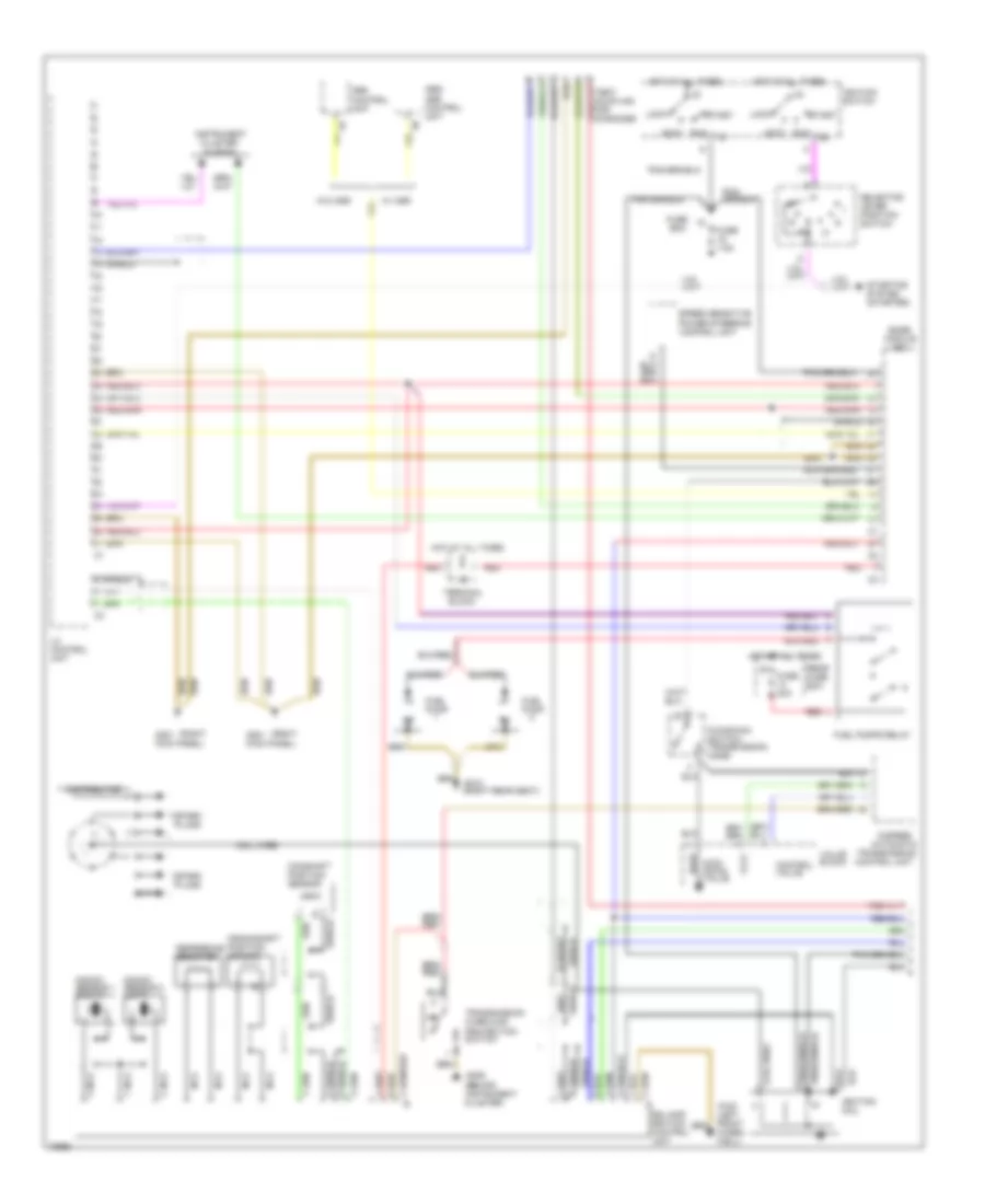
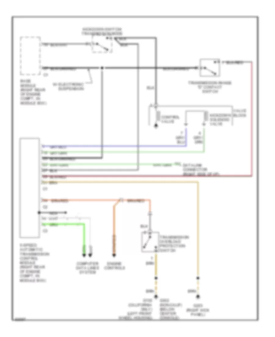
TRANSMISSION Transmission Wiring Diagram for Mercedes-Benz S320 1994 List of elements for Transmission Wiring Diagram for Mercedes-Benz S320 1994: 16 5-speed automatic transmission control module (right rear of engine compt, in module box) Base module (right rear of engine compt, in module box) Computer data lines system Control valve Datalink connector (right sdie of i/p) Engine controls G102 (california only) (left front wheel housing) G203 (right kick panel) G302 (non-calif) (below center console) Kickdown solenoid valve Kickdown switch/ transmission mode Nca Transmission overload protection switch Transmission range "d" contact switch Valve block W/ electronic suspension
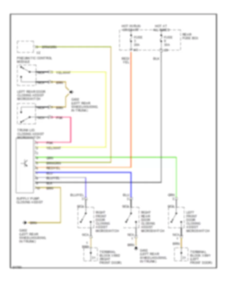
TRUNK, TAILGATE, FUEL DOOR Door Closing Assist Wiring Diagram for Mercedes-Benz S320 1994 List of elements for Door Closing Assist Wiring Diagram for Mercedes-Benz S320 1994: 17 4/3 Fuse 20a Fuse 30a G402 (left rear wheelhousing, in trunk) Hot at all times Hot in run or start Left front door closing assist microswitch Left rear door closing assist microswitch Nca Pneumatic control module Pnk Rear fuse box Right front door closing assist microswitch Right rear door closing assist microswitch Terminal block x99/1 (left front door) Terminal block x99/2 (right front door) Trunk lid closing assist microswitch
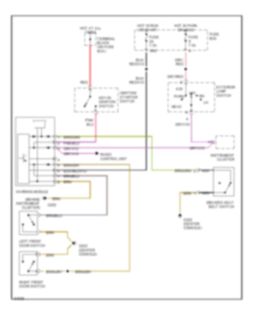
WARNING SYSTEMS Warning System Wiring Diagrams for Mercedes-Benz S320 1994 List of elements for Warning System Wiring Diagrams for Mercedes-Benz S320 1994: 25 (behind instrument cluster) 36/2 Driver's seat belt switch Exterior lamp switch Fuse 7.5a Fuse box G202 G302 (center console) Head Hot at all times Hot in park or head Hot in run or start Ignition/ starter switch Instrument cluster K30 Key-in iginition switch Left front door switch Nca Off Park Radio control unit Red Right front door switch Terminal block (on fuse box) Warning module
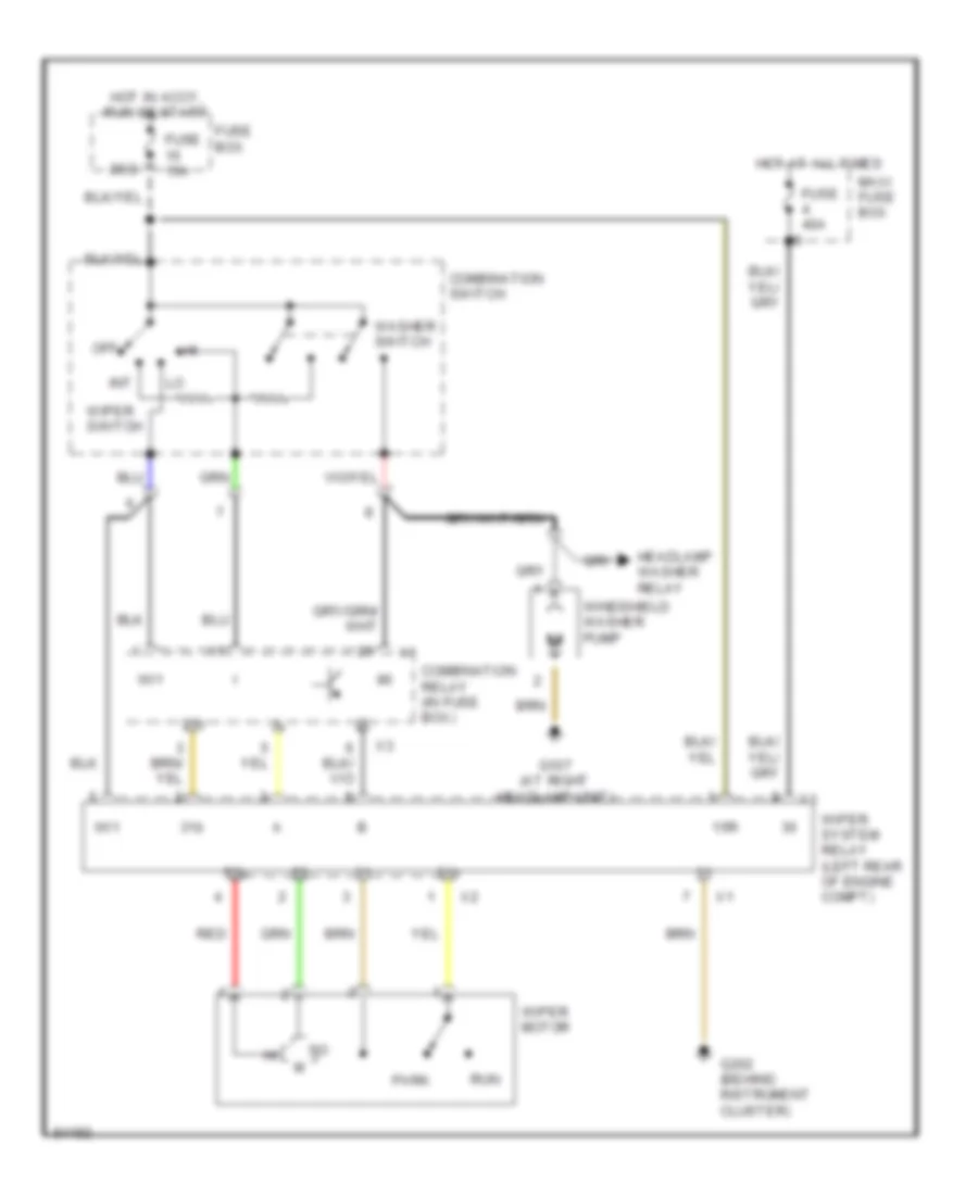
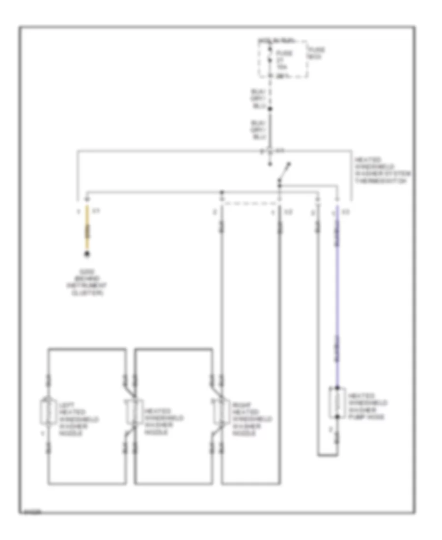
WIPER/WASHER Front Wiper/Washer Wiring Diagram for Mercedes-Benz S320 1994 List of elements for Front Wiper/Washer Wiring Diagram for Mercedes-Benz S320 1994: 26 15r 20/2 31b 53b Combination relay (in fuse box) Combination switch Fuse 15a Fuse 40a Fuse box G107 (at right headlamp unit) G202 (behind instrument cluster) Headlamp washer relay Hot at all times Hot in accy, run or start Int Maxi fuse box Off Park Red Run Washer switch Wi1 Windshield washer pump Wiper motor Wiper switch Wiper system relay (left rear of engine compt) Headlamp Wiper/Washer Wiring Diagram for Mercedes-Benz S320 1994 List of elements for Headlamp Wiper/Washer Wiring Diagram for Mercedes-Benz S320 1994: 24 (at left headlamp unit) 20/2 Combination relay Combination switch Fuse 15a Fuse box G106 G106 (at left headlamp unit) G107 (at right headlamp unit) Head Head- lamp washer relay (in fuse box) Headlamp washer pump Hot at all times Hot in accy, run or start Left headlamp wiper motor Light switch Off Park Red Right headlamp wiper motor Run Wash Washer switch Windshield washer pump Heated Windshield Washer Wiring Diagram for Mercedes-Benz S320 1994 List of elements for Heated Windshield Washer Wiring Diagram for Mercedes-Benz S320 1994: 10 28/1 Fuse 15a Fuse box G202 (behind instrument cluster) Heated windshield washer nozzle Heated windshield washer pump hose Heated windshield washer system thermoswitch Hot in run Left heated windshield washer nozzle Right heated windshield washer nozzle