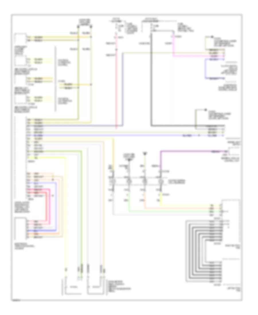
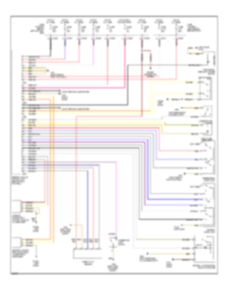
AIR CONDITIONING
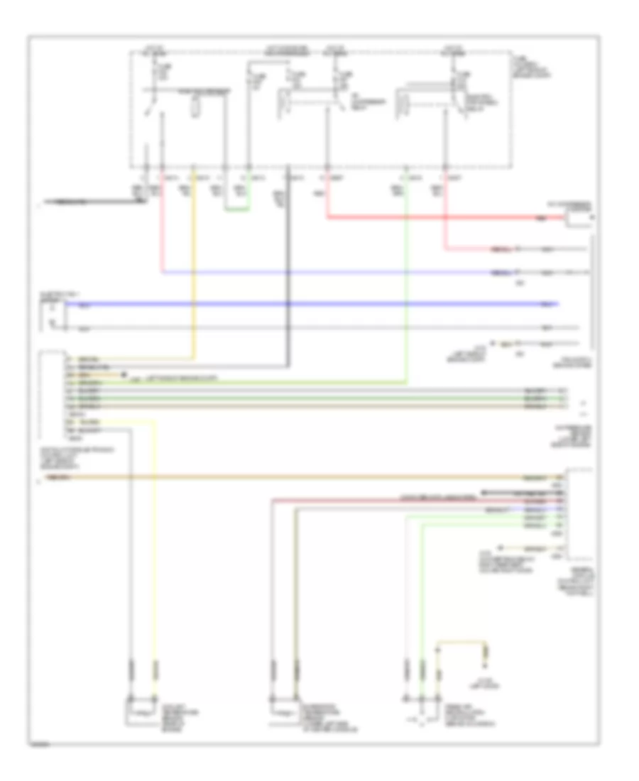
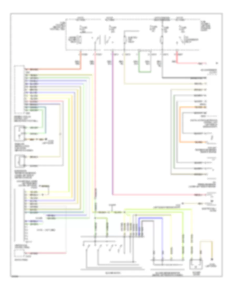
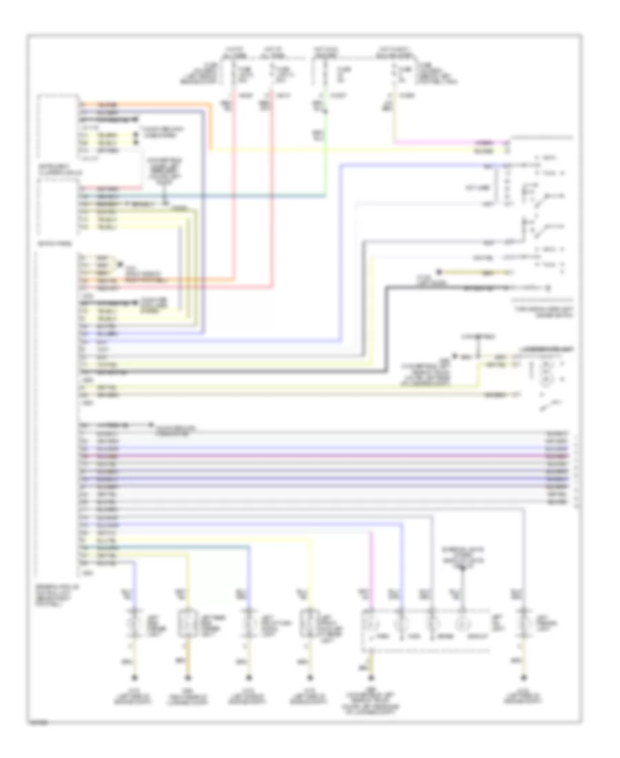
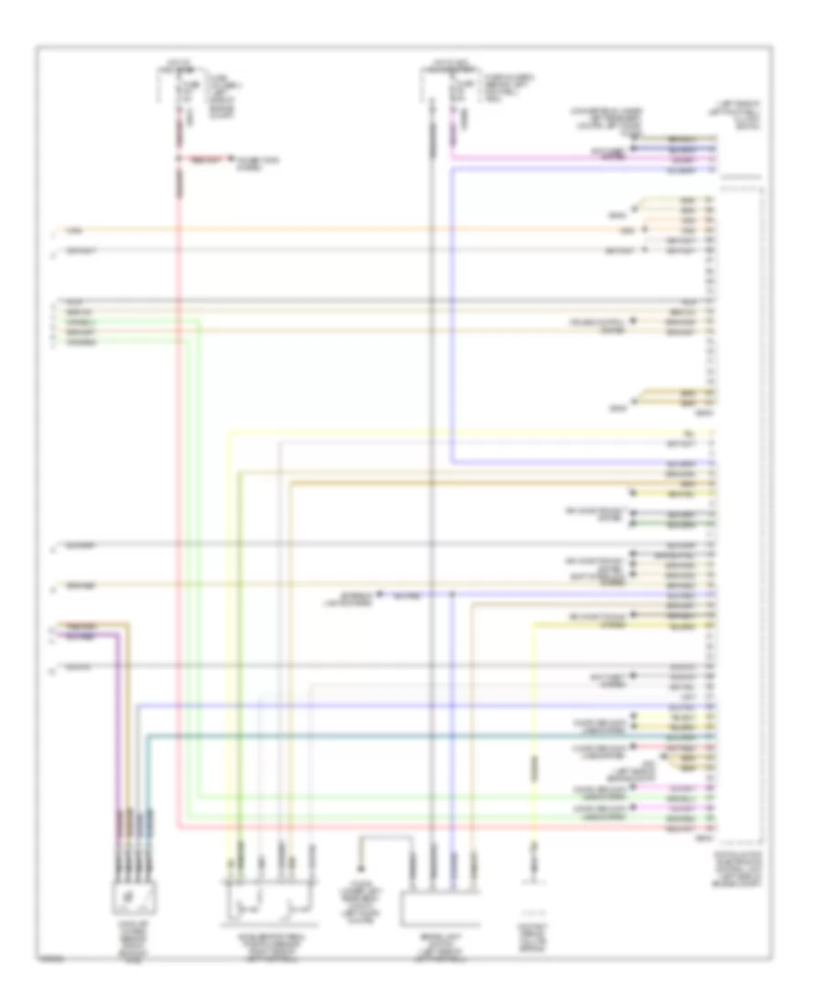
Automatic A/C Wiring Diagram, with Dual Stage Cooling Fans (1 of 2) for MINI Cooper S 2007

List of elements for Automatic A/C Wiring Diagram, with Dual Stage Cooling Fans (1 of 2) for MINI Cooper S 2007:
- (left door)
- Air distribution motor (center console)
- Air stratification flap motor (under right side of dash center console)
- Blower motor
- Blower output stage (center of dash)
- Computer data lines system
- Fuse f30 5a
- Fuse f31 30a
- Fuse f41 5a
- Fuse holder 2 (behind left footwell trim)
- Heat exchanger sensor (behind center of dash)
- Heater blower relay
- Heating & a/c control module
- Hot at all times
- Hot in accy, run and start
- Hot in on or start
- Interior temperature sensor
- Nca
- Power steering control module fan
- Red
- Solar sensor (top of dash)
- Steering control module fan relay (left side of left footwell)
- Switch panel
- X10201
- X10205
- X10207
- X1108
- X1108 (left door)
- X13230 (under left rear seat) (convertible) (left door) (coupe)
- X1879
- X610
- X6454
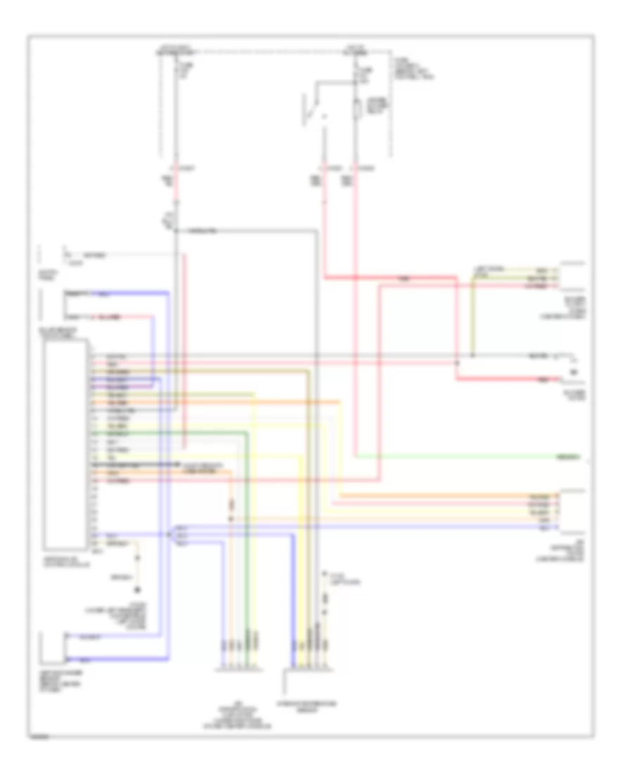
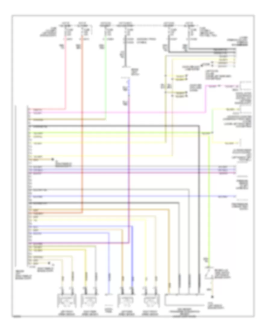
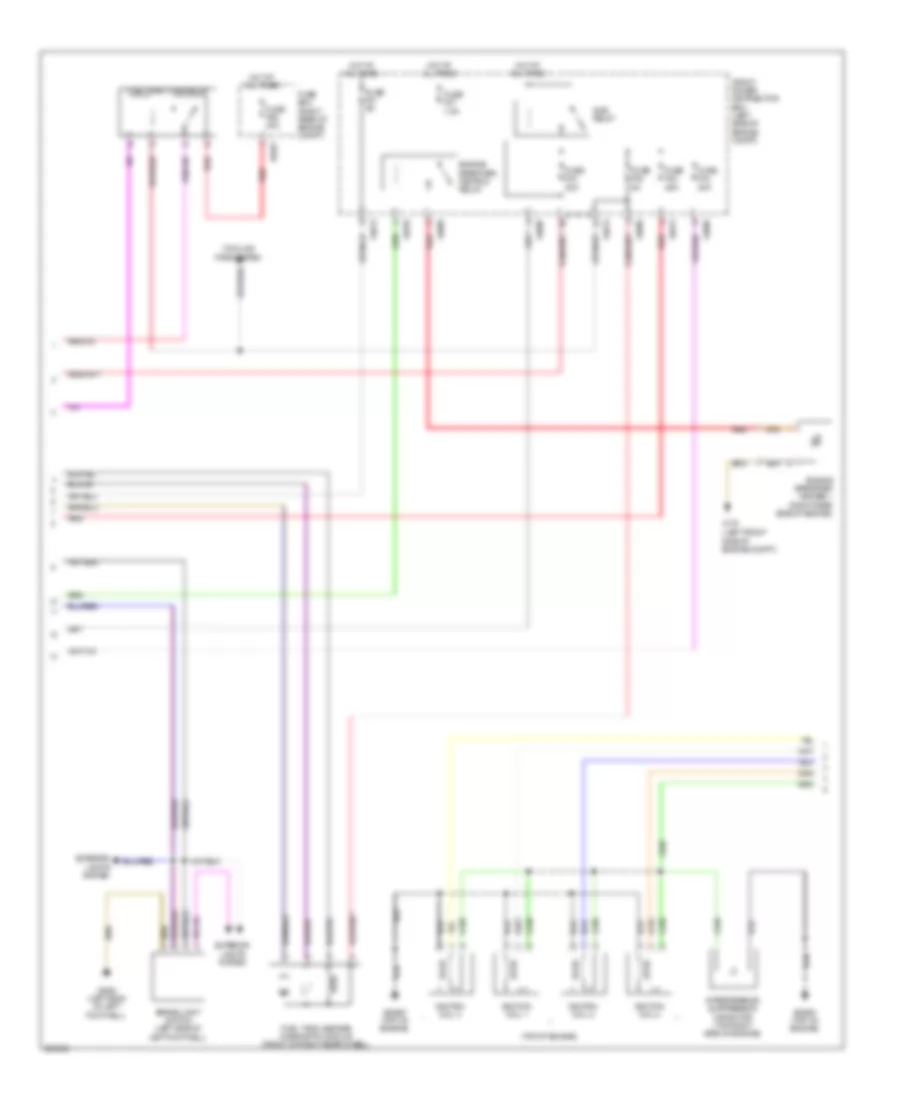
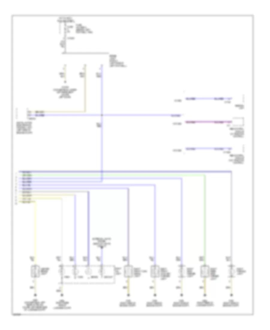
Automatic A/C Wiring Diagram, with Dual Stage Cooling Fans (2 of 2) for MINI Cooper S 2007
List of elements for Automatic A/C Wiring Diagram, with Dual Stage Cooling Fans (2 of 2) for MINI Cooper S 2007:
- (left side of engine compt)
- A/c compressor clutch
- A/c compressor relay
- A/c pressure sensor (lower left side of engine)
- Computer data lines system
- Coolant temperature sensor (rear of engine)
- Digital motor electronics control unit (left side of engine compt)
- Electric fan 1 motor
- Electric fan relay
- Electric fan stage 2 relay
- Evaporator temperature sensor (under left side of center console)
- Fan switch second stage
- Fresh air/ recirculation flap motor (behind glove box)
- Fuse f03 15a
- Fuse f05 5a
- Fuse f07 30a
- Fuse f08 30a
- Fuse fl9 50a
- Fuse holder 3 (left side of engine compt)
- General module control unit (behind right footwell)
- Hot at all times
- Hot w/ dme main relay energized
- Nca
- Red
- X1108 (left door)
- X167
- X175 (left side of engine compt)
- X179 (convertible: below right rear seat) (coupe: right door)
- X253
- X254
- X255
- X4007
- X4010
- X4013
- X4014
- X53
- X6000
- X60004
- X8687
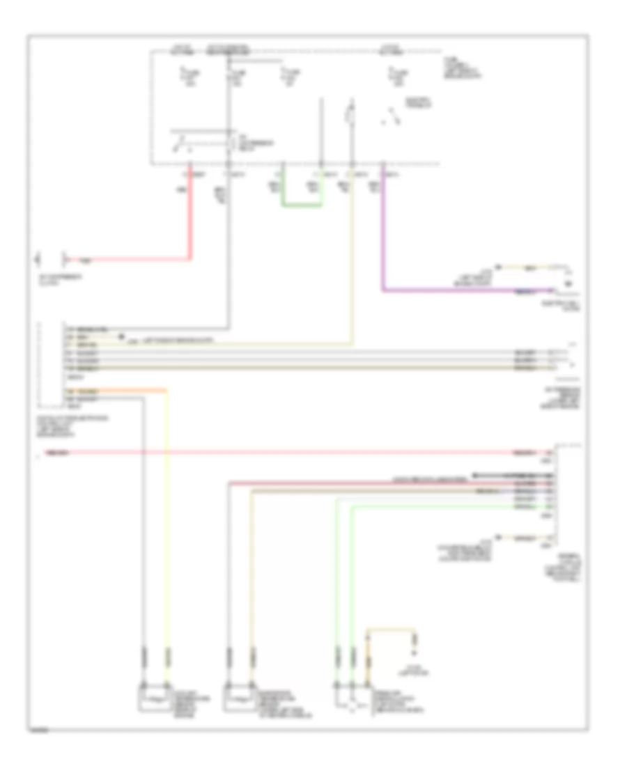
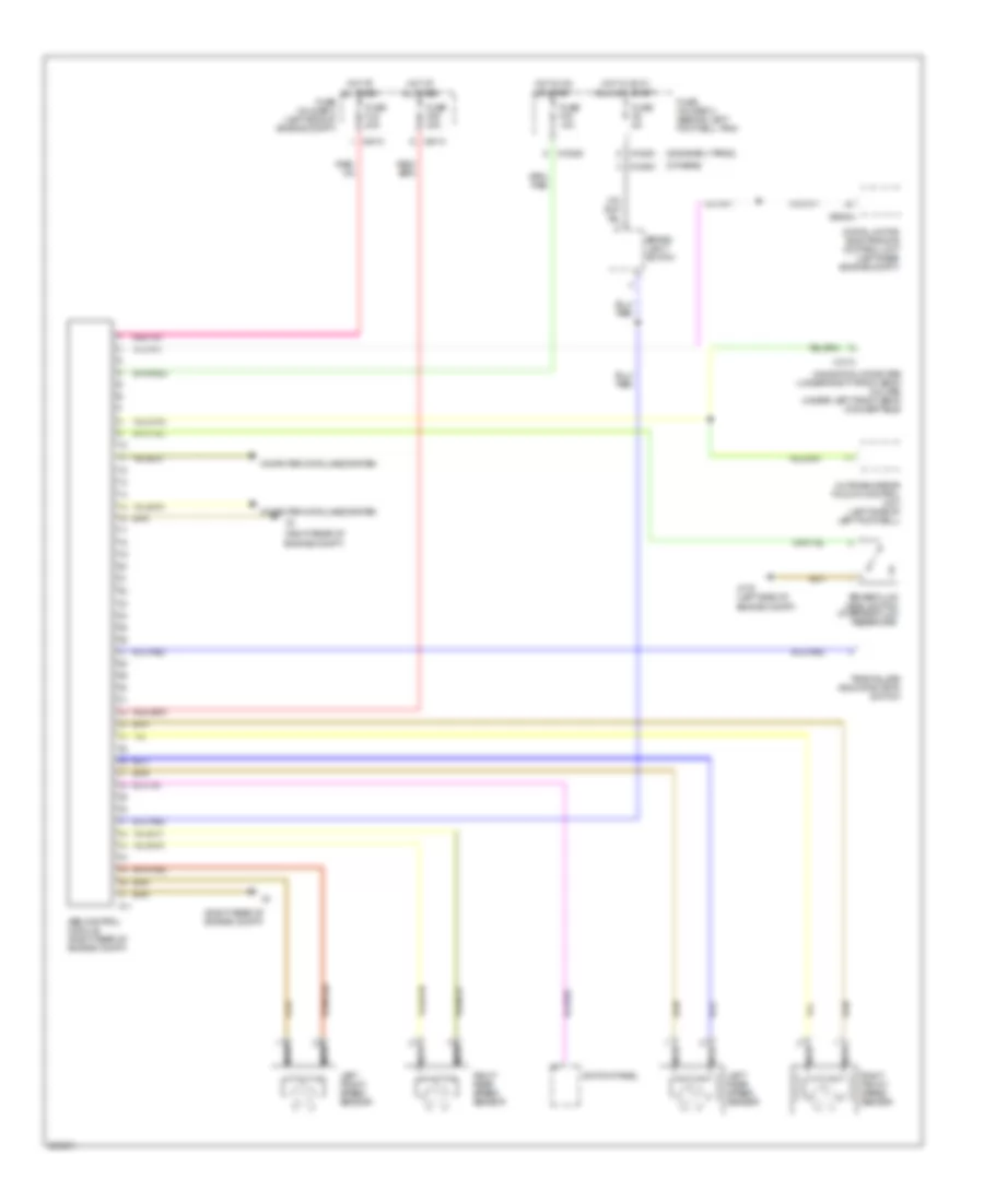
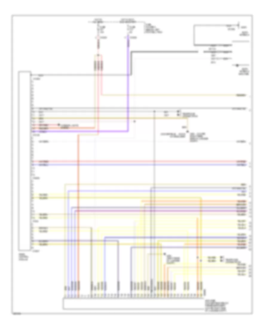
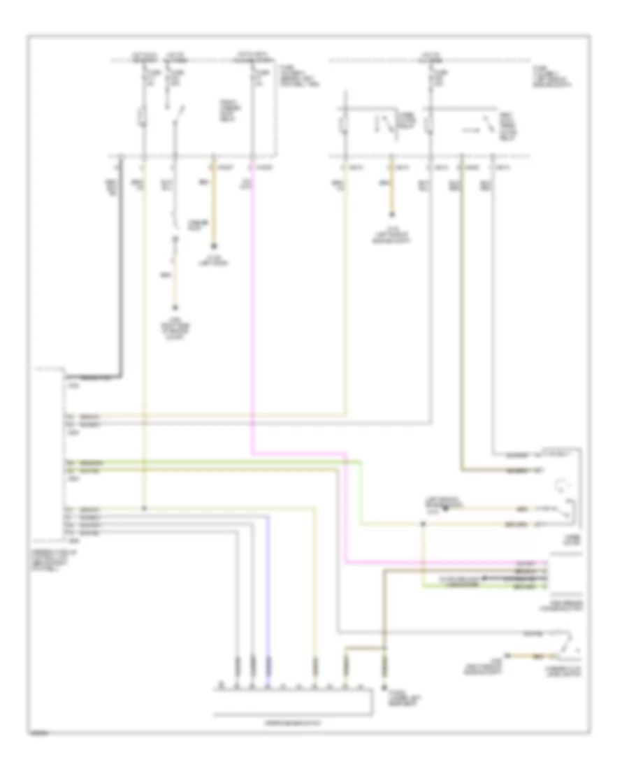
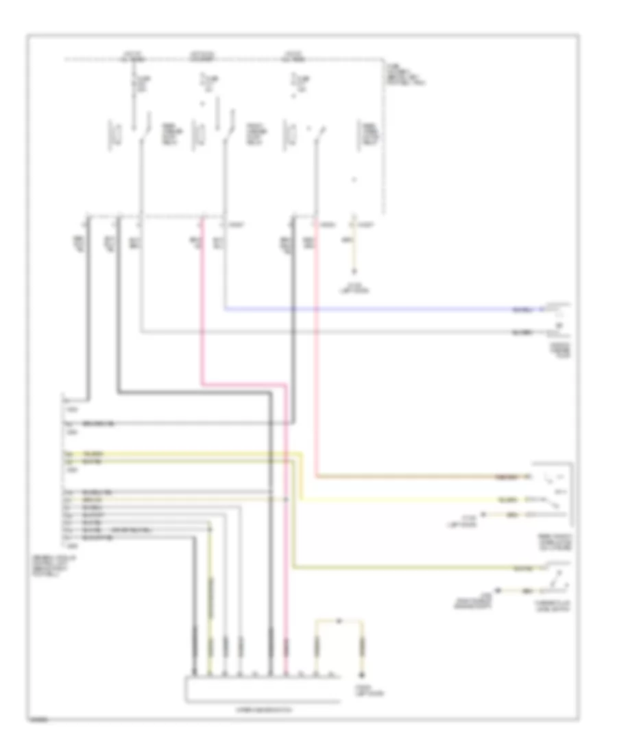
Automatic A/C Wiring Diagram, with Single Stage Cooling Fans (1 of 2) for MINI Cooper S 2007
List of elements for Automatic A/C Wiring Diagram, with Single Stage Cooling Fans (1 of 2) for MINI Cooper S 2007:
- (left door) x1108
- Air distribution motor (center console)
- Air stratification flap motor (under right side of dash center console)
- Blower motor
- Blower output stage (center of dash)
- Computer data lines system
- Fuse f30 5a
- Fuse f31 30a
- Fuse holder 2 (behind left footwell trim)
- Heat exchanger sensor (behind center of dash)
- Heater blower relay
- Heating & a/c control module
- Hot at all times
- Hot in accy, run and start
- Interior temperature sensor
- Nca
- Red
- Solar sensor (top of dash)
- Switch panel
- X10201
- X10205
- X10207
- X1108 (left door)
- X13230 (under left rear seat) (convertible) (left door) (coupe)
- X1879
- X610
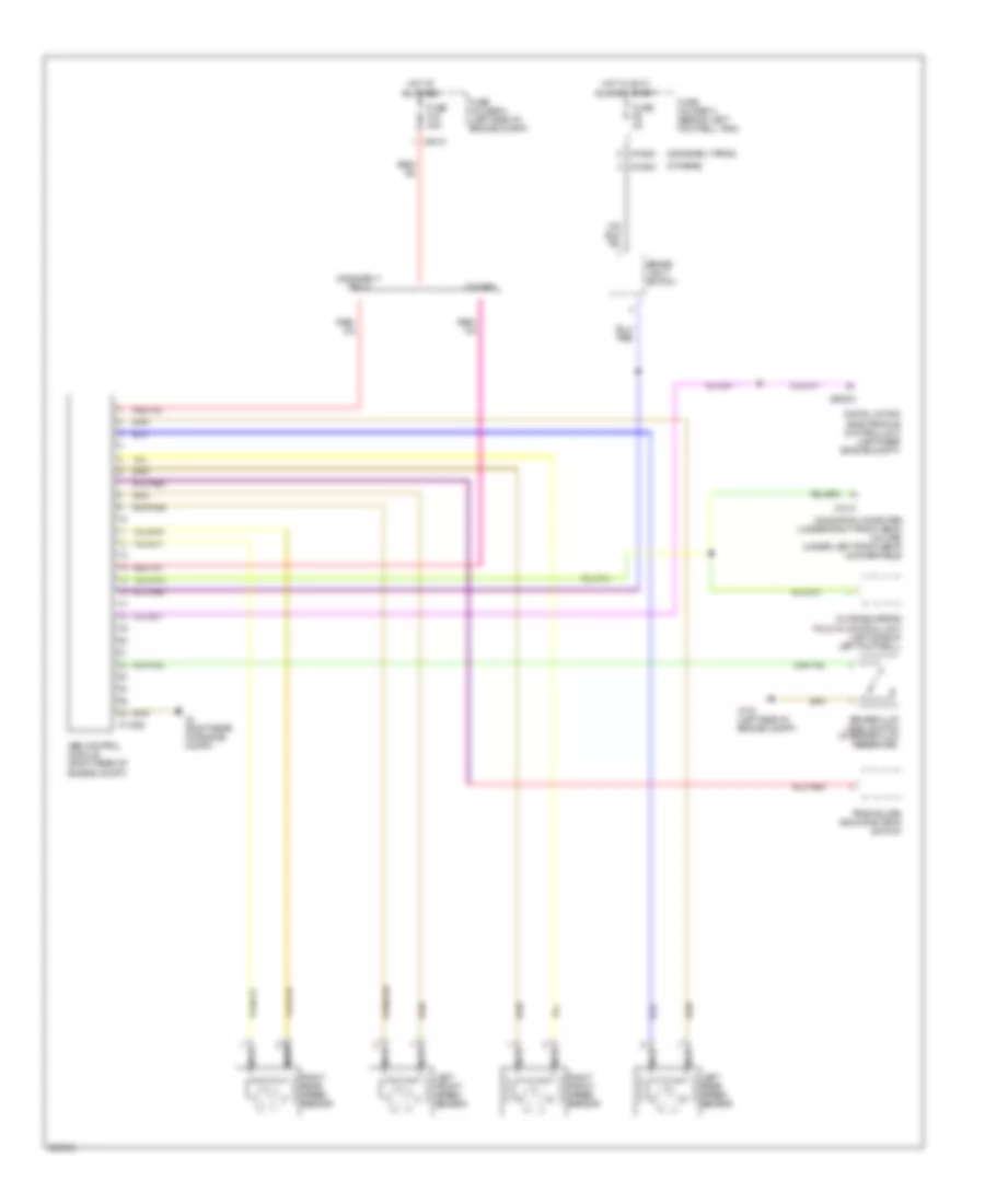
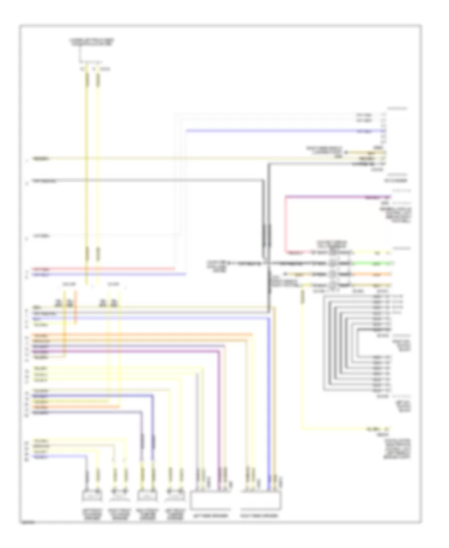
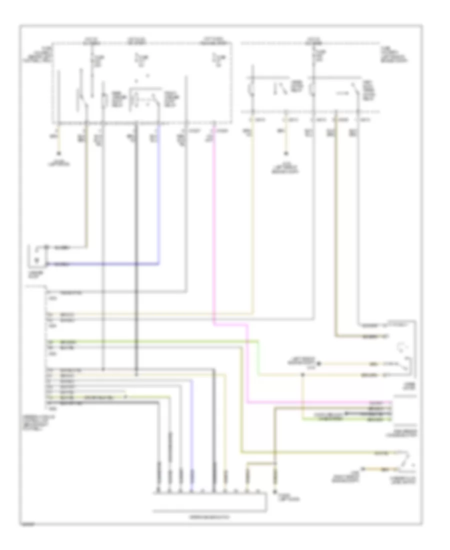
Automatic A/C Wiring Diagram, with Single Stage Cooling Fans (2 of 2) for MINI Cooper S 2007
List of elements for Automatic A/C Wiring Diagram, with Single Stage Cooling Fans (2 of 2) for MINI Cooper S 2007:
- (left side of engine compt)
- A/c compressor clutch
- A/c compressor relay
- A/c pressure sensor (lower left side of engine)
- Computer data lines system
- Coolant temperature sensor (rear of engine)
- Digital motor electronics control unit (left side of engine compt)
- Electric fan 1 motor
- Electric fan relay
- Evaporator temperature sensor (under left side of center console)
- Fresh air/ recirculation flap motor (behind glove box)
- Fuse f03 15a
- Fuse f05 5a
- Fuse f07 30a
- Fuse f08 20a
- Fuse holder 3 (left side of engine compt)
- General module control unit (behind right footwell)
- Hot at all times
- Hot w/ dme main relay energized
- Red
- X1108 (left door)
- X167
- X175 (left side of engine compt)
- X179 (convertible: below right rear seat) (coupe: right door)
- X253
- X254
- X255
- X4010
- X4013
- X4014
- X6000
- X60004
- X8687
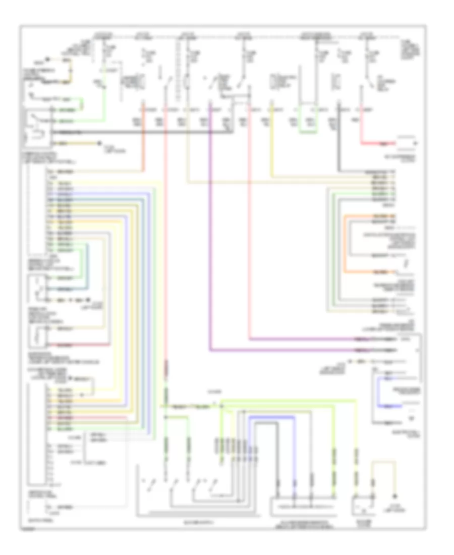
Manual A/C Wiring Diagram, with Dual Stage Cooling Fans for MINI Cooper S 2007
List of elements for Manual A/C Wiring Diagram, with Dual Stage Cooling Fans for MINI Cooper S 2007:
- (convertible: under left rear seat) (coupe: left door) x13230
- (left door)
- (not used)
- (or red)
- A/c compres- sor relay
- A/c compressor clutch
- A/c pressure sensor (lower left side of engine)
- Blower motor
- Blower series resistor (below left side of glove box)
- Blower switch
- Coolant temperature sensor (rear of engine)
- Digital motor electronics control unit (left side of engine compt)
- Elec- tric fan stage relay
- Electric fan 1 motor
- Electric fan relay
- Evaporator temperature sensor (under left side of center console)
- Fresh air/ recirculation flap motor (behind glove box)
- Fuse f03 15a
- Fuse f05 5a
- Fuse f07 30a
- Fuse f08 30a
- Fuse f31 30a
- Fuse f41 5a
- Fuse fl9 50a
- Fuse holder 2 (behind left footwell trim)
- Fuse holder 3 (left side of engine compt)
- General module control unit (behind right footwell)
- Heater blower relay
- Heating & a/c control panel
- Hot at all times
- Hot in on or start
- Hot w/ dme main relay energized
- Nca
- Power steering control module fan
- Red
- Second stage fan switch
- Steering control module fan relay (left side of left footwell)
- Switch panel
- W/ ihkr
- W/ ihs
- X01117
- X10201
- X10205
- X10207
- X1108
- X1108 (left door)
- X175 (left side of engine comp)
- X1879
- X253
- X255
- X4007
- X4010
- X4013
- X4014
- X53
- X6000
- X60004
- X6454
- X8687
Manual A/C Wiring Diagram, with Single Stage Cooling Fans for MINI Cooper S 2007
List of elements for Manual A/C Wiring Diagram, with Single Stage Cooling Fans for MINI Cooper S 2007:
- (convertible: under left rear seat) (coupe: left door) x13230
- (left door)
- (not used)
- (or red)
- A/c compressor clutch
- A/c compressor relay
- A/c pressure sensor (lower left side of engine)
- Blower motor
- Blower series resistor (behind left side of glove box)
- Blower switch
- Coolant temperature sensor (rear of engine)
- Digital motor electronics control unit (left side of engine compt)
- Electric fan 1 motor
- Electric fan relay
- Evaporator temperature sensor (under left side of center console)
- Fresh air/ recirculation flap motor (behind glove box)
- Fuse f03 15a
- Fuse f05 5a
- Fuse f07 30a
- Fuse f08 20a
- Fuse f31 30a
- Fuse holder 2 (behind left footwell trim)
- Fuse holder 3 (left side of engine compt)
- General module control unit (behind right footwell)
- Heater blower relay
- Heating & a/c control panel
- Hot at all times
- Hot w/ dme main relay energized
- Red
- Switch panel
- W/ ihkr
- W/ ihs
- X01117
- X10201
- X10205
- X1108
- X1108 (left door)
- X175 (left side of engine compt)
- X1879
- X253
- X255
- X4010
- X4013
- X4014
- X6000
- X60004
- X8687
ANTI-LOCK BRAKES
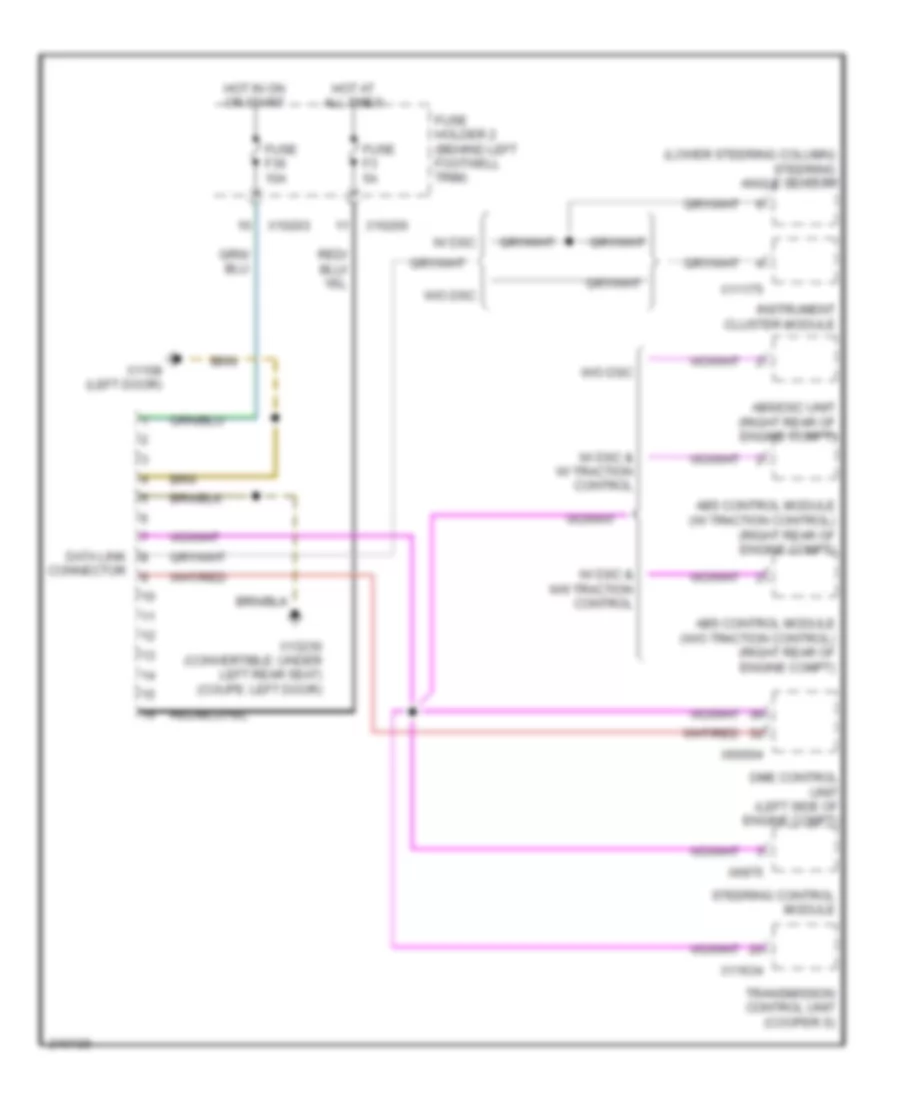
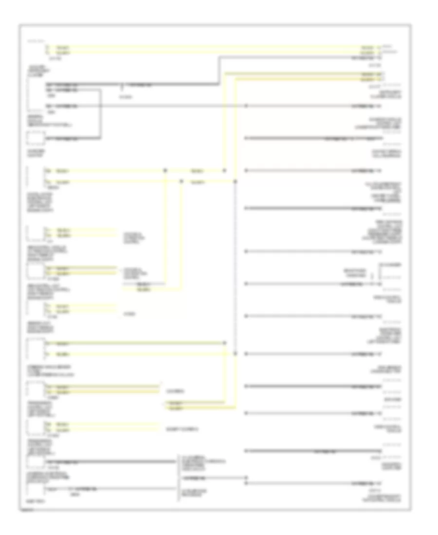
Anti-lock Brakes Wiring Diagram, with Dynamic Stability Control for MINI Cooper S 2007
List of elements for Anti-lock Brakes Wiring Diagram, with Dynamic Stability Control for MINI Cooper S 2007:
- (2006 early prod)
- (left door) (coupe) (under left rear seat) (convertible)
- (lower steering column) steering angle sensor
- (others)
- (right rear of engine compt)
- Abs/dsc unit (right rear of engine compt)
- Brake fluid level switch (left side of engine compt)
- Brake light switch
- Computer data lines system
- Digital motor electronics control unit (left rear engine compt)
- Dsc sensor (transverse acceleration sensor) (under lever cover)
- Fuse f06 30a
- Fuse f2 5a
- Fuse f33 10a
- Fuse f40 5a
- Fuse f6 5a
- Fuse fl6 40a
- Fuse holder 2 (behind left footwell trim)
- Fuse holder 3 (left side of engine compt)
- Hot at all times
- Hot in accy, run and start
- Hot in on or start
- Left front speed sensor
- Left rear speed sensor
- Navigation computer (under right front seat) (coupe) (under left front seat) (convertible)
- Nca
- Outside mirror fold-in control unit (left side of left footwell)
- Pressure sensor (in left water box)
- Right front speed sensor
- Right rear speed sensor
- Switch panel
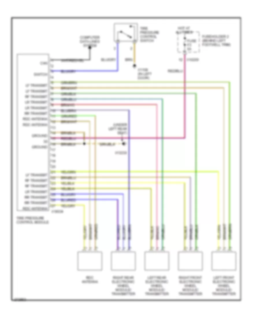
- Tire pressure warning (rdm) switch
- X10200
- X10205
- X10207
- X1313
- X13230
- X1746
- X175 (left side of engine compt)
- X4 (right rear of engine compt)
- X4010
- X4013
- X6004
Anti-lock Brakes Wiring Diagram, with Traction Control & without Dynamic Stability Control for MINI Cooper S 2007
List of elements for Anti-lock Brakes Wiring Diagram, with Traction Control & without Dynamic Stability Control for MINI Cooper S 2007:
- (2006 early prod)
- (others)
- (right rear of engine compt)
- Abs control module (right rear of engine compt)
- Brake fluid level switch (in brake fluid reservoir)
- Brake light switch
- Computer data lines system
- Digital motor electronics control unit (left rear engine compt)
- Fuse f06 30a
- Fuse f33 10a
- Fuse f6 5a
- Fuse fl6 40a
- Fuse holder 2 (behind left footwell trim)
- Fuse holder 3 (left side of engine compt)
- Hot at all times
- Hot in accy, run and start
- Hot in on or start
- Left front speed sensor
- Left rear speed sensor
- Navigation computer (under right front seat) (coupe) (under left front seat) (convertible)
- Nca
- Outside mirror fold-in control unit (left side of left footwell)
- Right front speed sensor
- Right rear speed sensor
- Switch panel
- Tire failure indicator (rpa) switch
- X10200
- X10205
- X11
- X1313
- X175 (left side of engine compt)
- X4010
- X4013
- X60004
Anti-lock Brakes Wiring Diagram, without Traction Control & without Dynamic Stability Control for MINI Cooper S 2007
List of elements for Anti-lock Brakes Wiring Diagram, without Traction Control & without Dynamic Stability Control for MINI Cooper S 2007:
- (2006 early prod)
- (others)
- 2006 early prod
- Abs control module (right rear of engine compt)
- Brake fluid level switch (in brake fluid reservoir)
- Brake light switch
- Digital motor electronics control unit (left rear engine compt)
- Fuse f6 5a
- Fuse fl6 40a
- Fuse holder 2 (behind left footwell trim)
- Fuse holder 3 (left side of engine compt)
- Hot at all times
- Hot in accy, run and start
- Left front speed sensor
- Left rear speed sensor
- Navigation computer (under right front seat) (coupe) (under left front seat) (convertible)
- Nca
- Others
- Outside mirror fold-in control unit (left side of left footwell)
- Right front speed sensor
- Right rear speed sensor
- Tire failure indicator (rpa) switch
- X10200
- X11525
- X1313
- X175 (left side of engine compt)
- X4 (right rear of engine compt.)
- X4010
- X60004
ANTI-THEFT
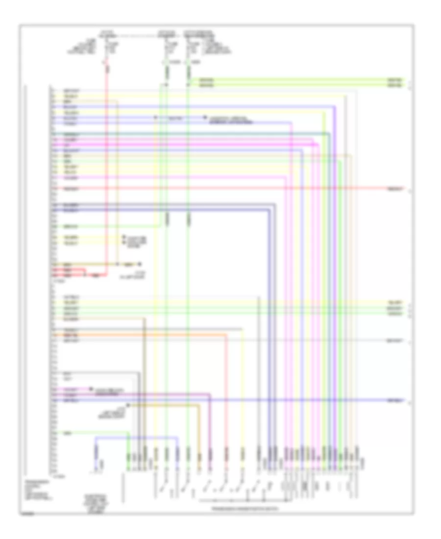
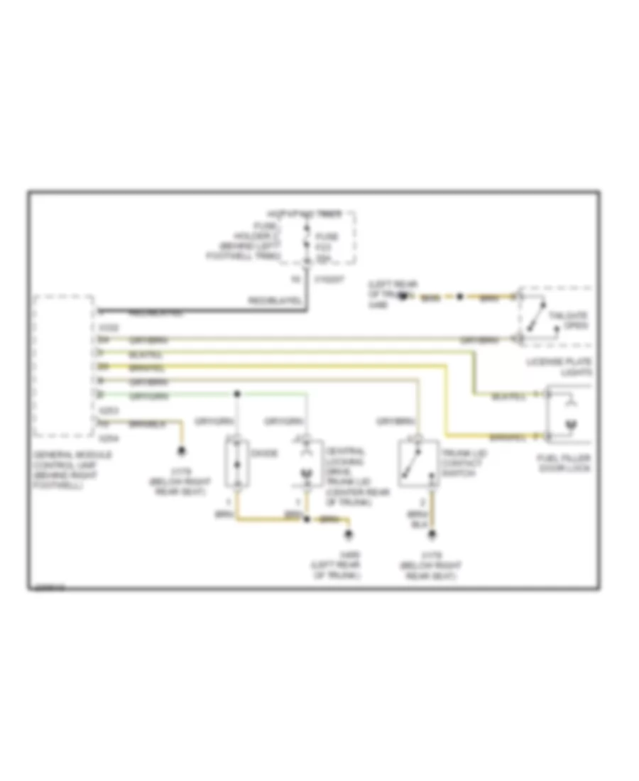
Anti-theft Wiring Diagram, Convertible for MINI Cooper S 2007
List of elements for Anti-theft Wiring Diagram, Convertible for MINI Cooper S 2007:
- (left door) x1108
- (left rear of trunk)
- (right side of engine compt)
- Central locking drive, trunk lid/tailgate (center rear of trunk)
- Computer data lines system
- Diode
- Driver's door lock
- Driver's door microwave sensor
- Fuel filler door lock
- Fuse f1 30a
- Fuse f14 10a
- Fuse f19 30a
- Fuse f23 20a
- Fuse f24 5a
- Fuse f4 5a
- Fuse f7 5a
- Fuse fl 12 50a
- Fuse fl 8 50a
- Fuse holder 2 (behind left footwell trim)
- Fuse holder 3 (left side of engine compt)
- General module control unit (behind right footwell)
- Hot at all times
- Hot in accy, run and start
- License plate lights
- Not used
- Passenger's door lock
- Passenger's door microwave sensor
- Rear left microwave sensor
- Rear right microwave sensor
- Red
- Siren w/ tilt alarm sensor
- Switch panel
- Theft ind
- Trunk lid contact switch
- Turn signal/ headlight dimmer switch
- Underhood light switch
- X10200
- X10201
- X10202
- X10206
- X10207
- X1108 (left door)
- X13230 (under left rear seat)
- X151 (right side of right footwell)
- X165
- X165 (right side of engine compt)
- X179 (below right rear seat)
- X253
- X254
- X255
- X332
- X4009
- X4010
- X490
- X490 (left rear of trunk)
- X494 (right rear side of luggage compt)
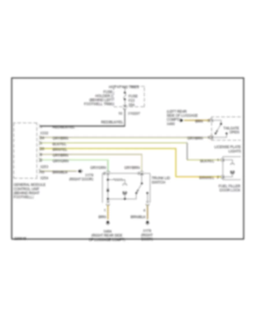
Anti-theft Wiring Diagram, Except Convertible for MINI Cooper S 2007
List of elements for Anti-theft Wiring Diagram, Except Convertible for MINI Cooper S 2007:
- (left door) x1108
- (left rear side of luggage compt)
- (not used)
- (right side of engine compt)
- Central locking drive, trunk lid/tailgate
- Central locking remote control (under front headliner)
- Computer data lines system
- Driver's door lock
- Fuel filler door lock
- Fuse f1 30a
- Fuse f14 10a
- Fuse f19 30a
- Fuse f23 20a
- Fuse f24 5a
- Fuse f4 5a
- Fuse f7 5a
- Fuse fl 12 50a
- Fuse fl 8 50a
- Fuse holder 2 (behind left footwell trim)
- Fuse holder 3 (left side of engine compt)
- General module control unit (behind right footwell)
- Hot at all times
- Hot in accy, run and start
- Interior protection 1 control module (in headliner)
- License plate lights
- Passenger's door lock
- Power distribution system
- Red
- Siren w/ tilt sensor
- Switch panel
- Theft ind
- Turn signal/ headlight dimmer switch
- Underhood light switch
- X10200
- X10201
- X10202
- X10206
- X10207
- X1108 (left door)
- X13230 (left door)
- X151 (right side of right footwell)
- X165
- X165 (right side of engine compt)
- X179 (right door)
- X253
- X254
- X255
- X332
- X4009
- X4010
- X490
- X494 (right rear side of luggage compt)
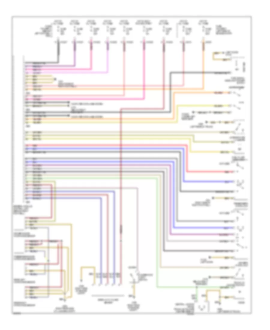
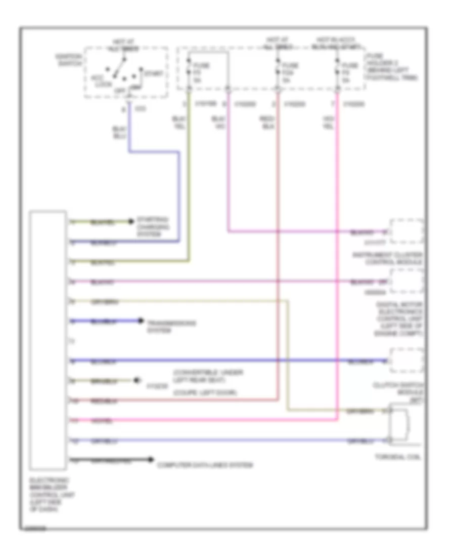
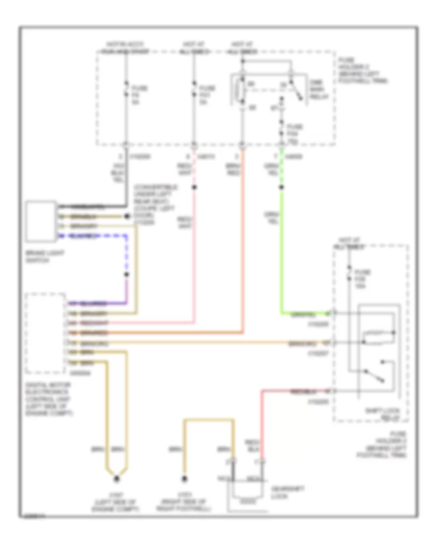
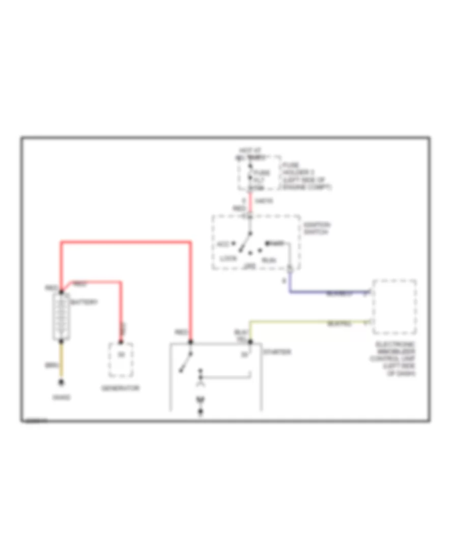
Immobilizer Wiring Diagram for MINI Cooper S 2007
List of elements for Immobilizer Wiring Diagram for MINI Cooper S 2007:
- (convertible: under left rear seat)
- (coupe: left door)
- Acc lock
- Clutch switch module (m/t)
- Computer data lines system
- Digital motor electronics control unit (left side of engine compt)
- Electronic immobilizer control unit (left side of dash)
- Fuse f24 5a
- Fuse f5 5a
- Fuse f6 5a
- Fuse holder 2 (behind left footwell trim)
- Hot at all times
- Hot in accy, run and start
- Ignition switch
- Instrument cluster control module
- Off
- Start
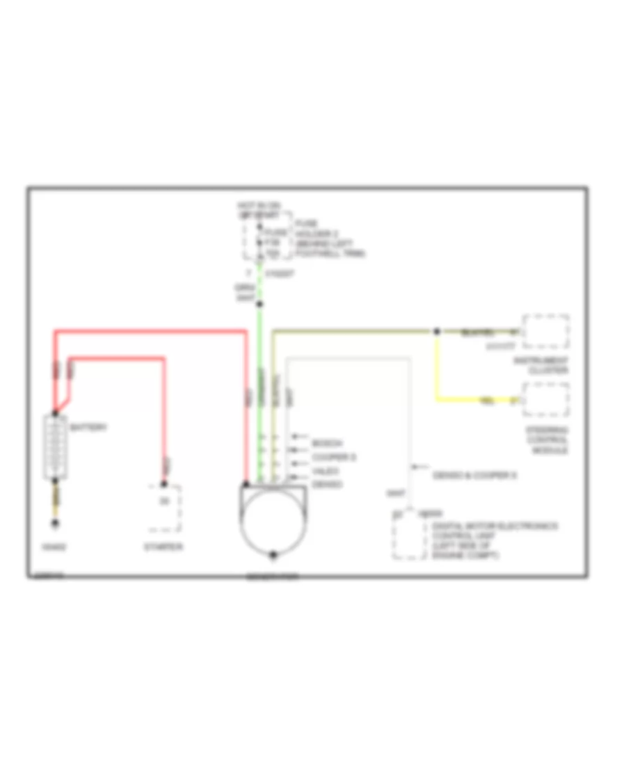
- Starting/ charging system
- Toroidal coil
- Transmissions system
- X10199
- X10200
- X11177
- X13230
- X33
- X60004
BODY CONTROL MODULES
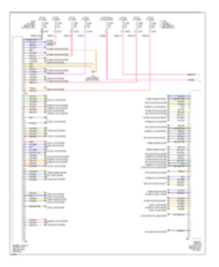
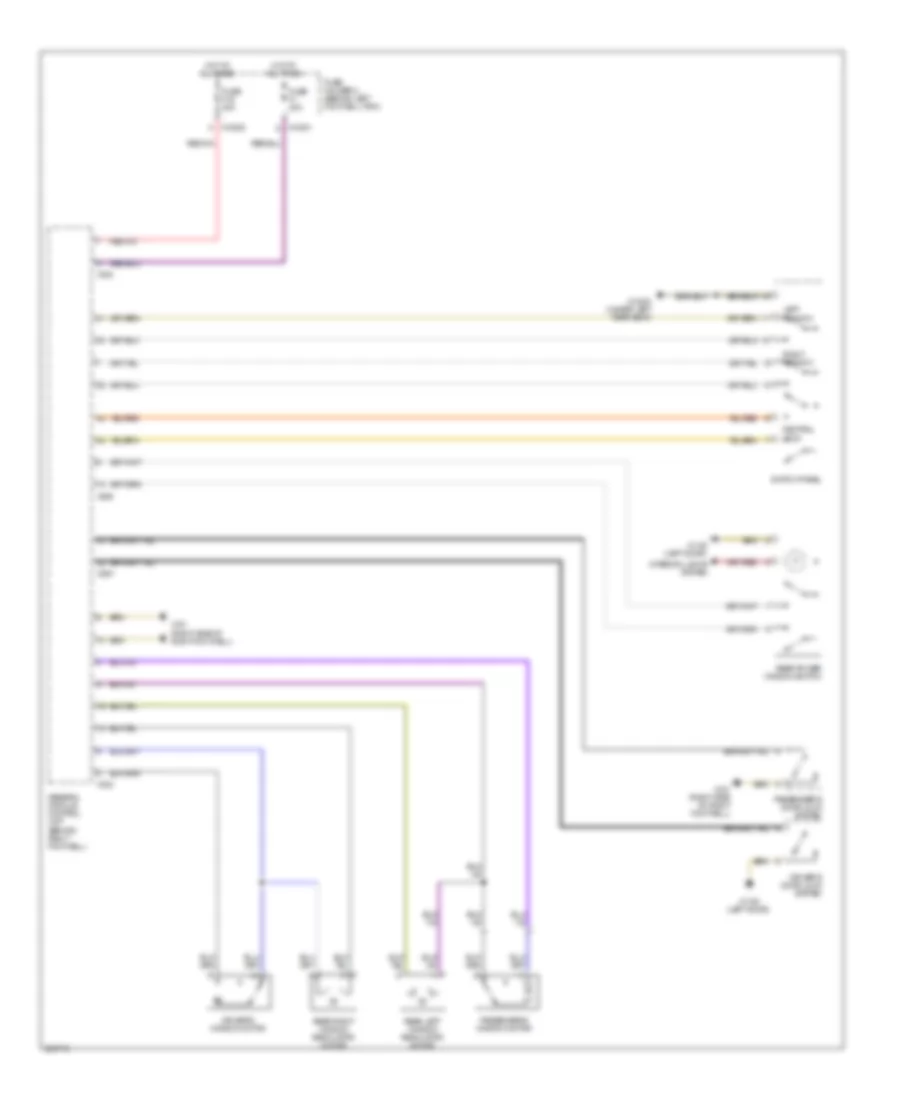
Body Control Modules Wiring Diagram (1 of 2) for MINI Cooper S 2007
List of elements for Body Control Modules Wiring Diagram (1 of 2) for MINI Cooper S 2007:
- Air conditioning system
- Anti-theft system
- Computer data lines system
- Cruise control system
- Door locks system
- Exterior lights system
- Fuse f1 30a
- Fuse f14 10a
- Fuse f19 30a
- Fuse f4 5a
- Fuse f7 5a
- Fuse fl 12 50a
- Fuse fl 8 50a
- Fuse holder 2 (behind left footwell trim)
- Fuse holder 3 (left side of engine compt)
- Fuse f32 20a
- General module control unit (behind right footwell)
- Headlights system
- Hot at all times
- Hot in accy, run and start
- Interior lights system
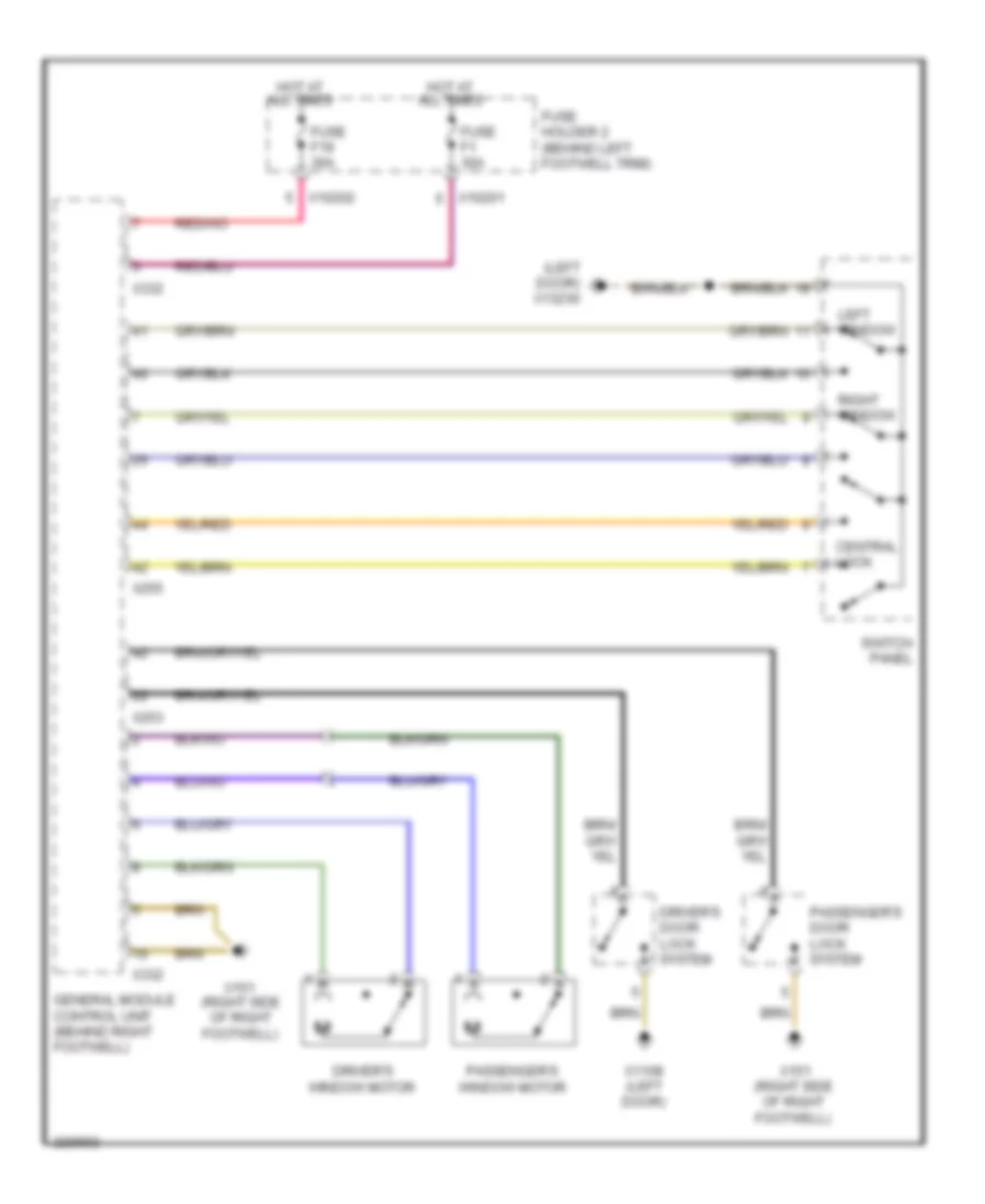
- Power windows system
- Power windows systems
- Red
- Wiper/washer system
- X10201
- X10202
- X10206
- X10207
- X151 (right side of right footwell)
- X253
- X255
- X332
- X4009
- X4010
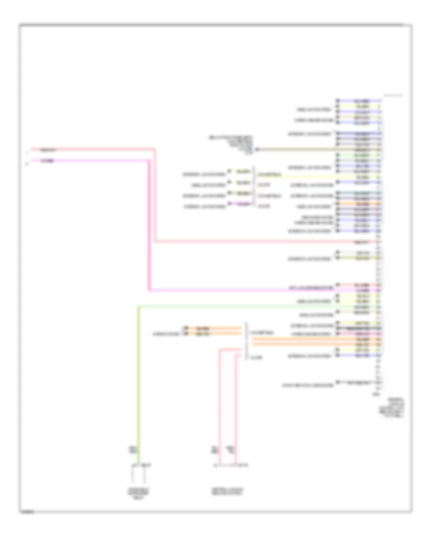
Body Control Modules Wiring Diagram (2 of 2) for MINI Cooper S 2007
List of elements for Body Control Modules Wiring Diagram (2 of 2) for MINI Cooper S 2007:
- (below right rear seat) (convertible) (right door) (coupe) x179
- Anti-lock brakes system
- Central locking remote control
- Computer data lines system
- Convertible
- Coupe
- Defogger system
- Exterior lights system
- General module control unit (behind right footwell)
- Headlights system
- Interior lights system
- Mirror system
- Windshield defroster relay
- Wiper/washer system
- X1143
- X254
- X3148
COMPUTER DATA LINES
Data Link Connector Wiring Diagram for MINI Cooper S 2007
List of elements for Data Link Connector Wiring Diagram for MINI Cooper S 2007:
- (lower steering column) steering angle sensor
- Abs control module (w/ traction control) (right rear of engine compt)
- Abs control module (w/o traction control) (right rear of engine compt)
- Abs/dsc unit (right rear of engine compt)
- Connector
- Data link
- Dme control unit (left side of engine compt)
- Fuse f3 5a
- Fuse f36 10a
- Fuse holder 2 (behind left footwell trim)
- Hot at all times
- Hot in on or start
- Instrument cluster module
- Steering control module
- Transmission control unit (cooper s)
- W/ dsc
- W/ dsc & w/ traction control
- W/ dsc & w/0 traction control
- W/o dsc
- X10200
- X10203
- X1108 (left door)
- X11175
- X11634
- X13230 (convertible: under left rear seat) (coupe: left door)
- X60004
- X6975
High/Low Bus Wiring Diagram for MINI Cooper S 2007
List of elements for High/Low Bus Wiring Diagram for MINI Cooper S 2007:
- Abs control module (w/ traction control) (right rear of engine compt)
- Abs control unit (w/o traction control) (right rear of engine compt)
- Abs/dsc unit (right rear of engine compt)
- Amplifier
- Auxiliary
- Boost radio
- Cd changer
- Cluster
- Contact spring (volute spring)
- Convertible soft top control module
- Cooper s
- Digital motor electronics control unit (left side of engine compt)
- Eject box
- Electronic immobilizer control unit (left side of dash)
- Except cooper s
- General module (behind right footwell)
- Instrument
- Instrument cluster module
- Multiple restraint system control unit (center tunnel, under carpet)
- Navigation computer
- Nca
- On-board monitor
- Park distance control unit (convt: right rear passenger compt) (coupe: right rear of luggage compt)
- Radio control module
- Rain sensor (windshield top)
- Steering angle sensor (w/ dsc) (lower steering column)
- Sunroof module control unit (under front headliner)
- Transmission control unit (left side of left footwell)
- Universal electronic charging & hands-free module (ulf)
- Video control module
- W/ dsc
- W/ ihka
- W/ telephone provisions
- W/ universal electronic charging & hands-free module (ulf)
- W/o dsc & w/ traction control
- W/o dsc & w/o traction control
- Wave radio
- X11
- X11175
- X11176
- X11177
- X11525
- X11633
- X1312
- X14133
- X1746
- X18114
- X19561
- X254
- X255
- X4545
- X60004
COOLING FAN
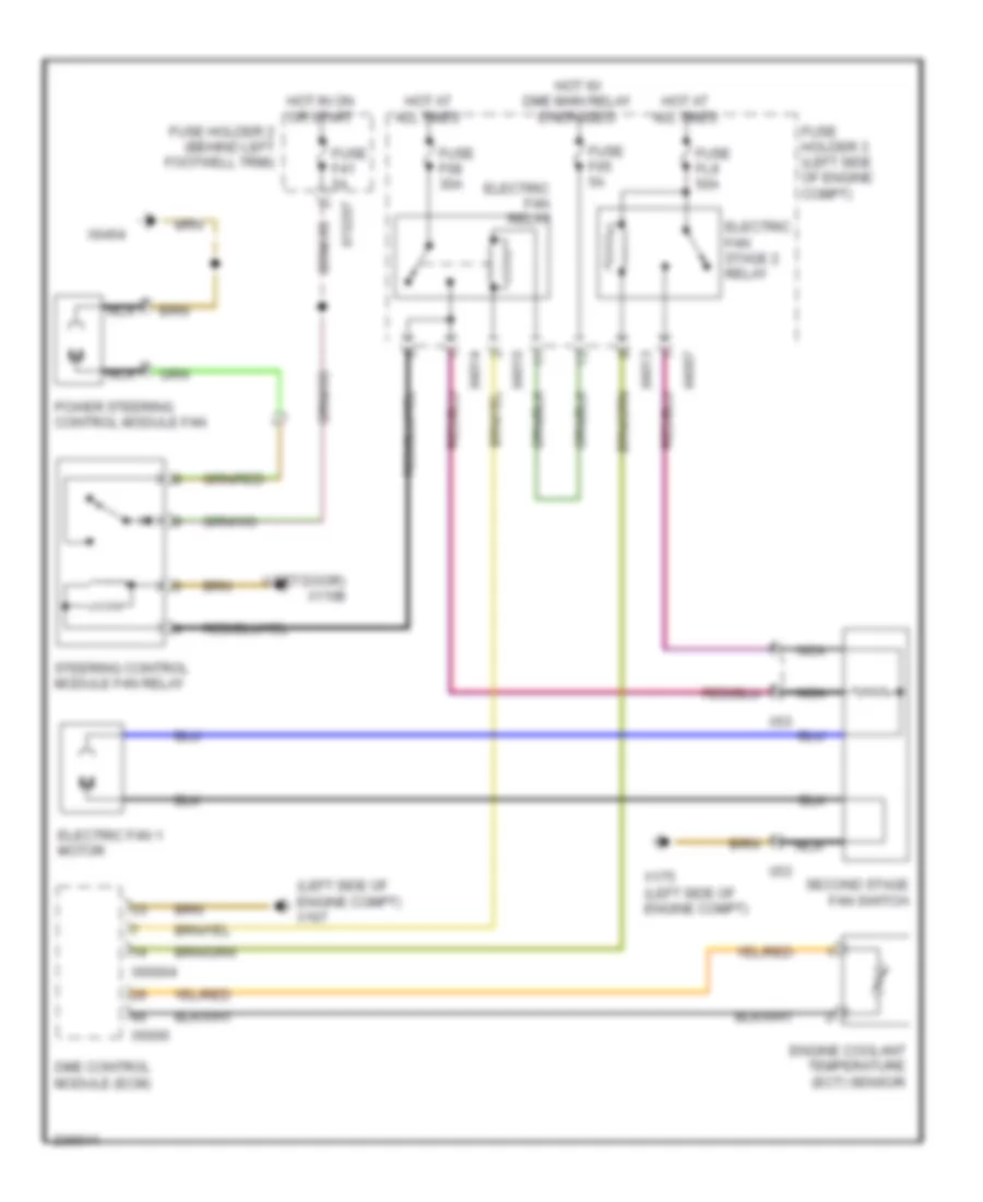
Cooling Fan Wiring Diagram, Dual Stage for MINI Cooper S 2007
List of elements for Cooling Fan Wiring Diagram, Dual Stage for MINI Cooper S 2007:
- (left door) x1108
- (left side of engine compt) x167
- Dme control module (ecm)
- Electric fan 1 motor
- Electric fan relay
- Electric fan stage 2 relay
- Engine coolant temperature (ect) sensor
- Fuse f05 5a
- Fuse f08 30a
- Fuse f41 5a
- Fuse fl9 50a
- Fuse holder 2 (behind left footwell trim)
- Fuse holder 3 (left side of engine compt)
- Hot at all times
- Hot in on or start
- Hot w/ dme main relay energized
- Nca
- Power steering control module fan
- Second stage fan switch
- Steering control module fan relay
- X10207
- X175 (left side of engine compt)
- X4007
- X4010
- X4013
- X4014
- X53
- X6000
- X60004
- X6454
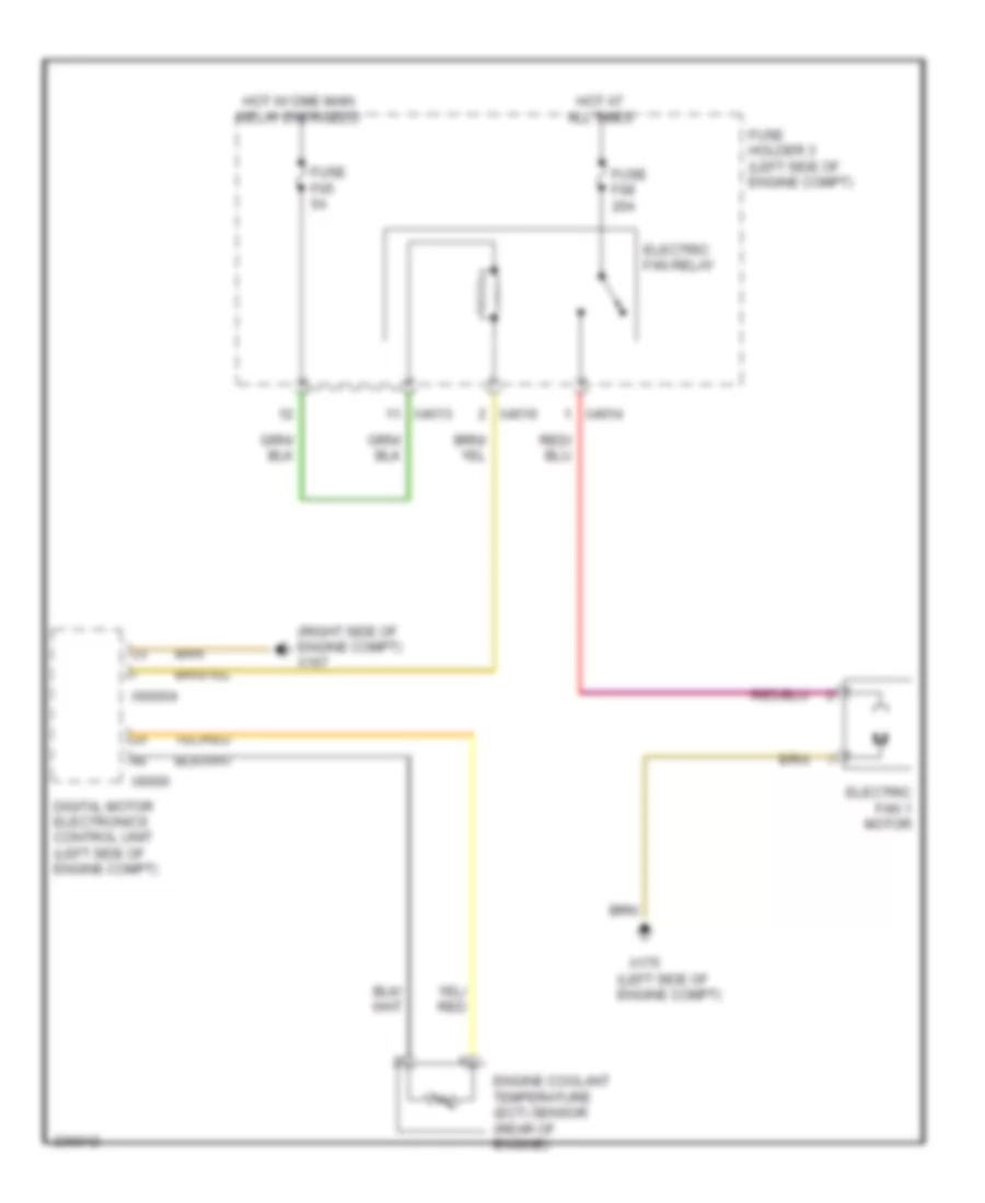
Cooling Fan Wiring Diagram, Single Stage for MINI Cooper S 2007
List of elements for Cooling Fan Wiring Diagram, Single Stage for MINI Cooper S 2007:
- (left side of engine compt)
- (right side of engine compt) x167
- Digital motor electronics control unit (left side of engine compt)
- Electric fan 1 motor
- Electric fan relay
- Engine coolant temperature (ect) sensor (rear of engine)
- Fuse f05 5a
- Fuse f08 20a
- Fuse holder 3 (left side of engine compt)
- Hot at all times
- Hot w/ dme main relay energized
- X175
- X4010
- X4013
- X4014
- X6000
- X60004
CRUISE CONTROL
Cruise Control Wiring Diagram for MINI Cooper S 2007
List of elements for Cruise Control Wiring Diagram for MINI Cooper S 2007:
- Abs control module (right rear of engine compt)
- Abs/dsc unit (right rear of engine compt)
- Accelerator pedal position sensor (below accelerator pedal)
- Brake light switch
- Clutch switch module (left side of left footwell)
- Computer data lines system
- Contact spring (volute spring)
- Digital motor electronics control unit (left side of engine compt)
- Electronic immobilizer (ews) control module
- Electronic throttle control housing
- Fuse 5a
- Fuse holder 2 (behind left footwell trim)
- Fuse holder 3 (left side of engine compt)
- General module control unit
- Hot at all times
- Hot in accy, run and start
- Instrument cluster control module
- Left button pad
- Nca
- Red
- Right button pad
- W/ dsc
- W/o dsc & w/ traction control
- W/o dsc & w/o traction control
- X01000
- X01001
- X01002
- X01003
- X10195
- X10200
- X11
- X11525
- X13230 (convertible: under left rear seat) (coupe: left door)
- X151
- X1746
- X255
- X4013
- X6000
- X60004
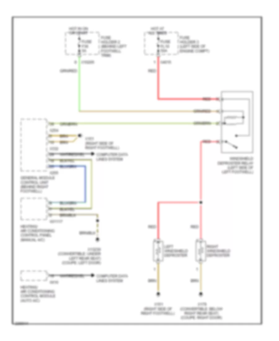
DEFOGGERS
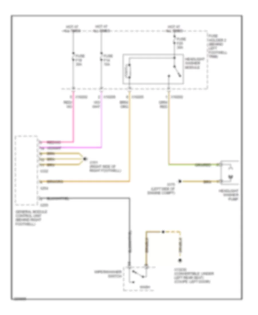
Heated Windshield Wiring Diagram for MINI Cooper S 2007
List of elements for Heated Windshield Wiring Diagram for MINI Cooper S 2007:
- Computer data lines system
- Fuse f36 5a
- Fuse fl10 50a
- Fuse holder 2 (behind left footwell trim)
- Fuse holder 3 (left side of engine compt)
- General module control unit (behind right footwell)
- Heating/ air conditioning control module (auto a/c)
- Heating/ air conditioning control panel (manual a/c)
- Hot at all times
- Hot in on or start
- Left windshield defroster
- Red
- Right windshield defroster
- Windshield defroster relay (left side of left footwell)
- X01117
- X10205
- X13230 (convertible: under left rear seat) (coupe: left door)
- X151 (right side of right footwell)
- X179 (convertible: below right rear seat) (coupe: right door)
- X254
- X255
- X332
- X4015
- X610
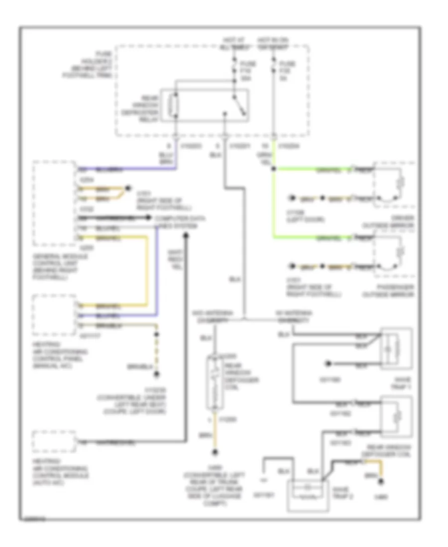
Rear Defogger & Heated Mirrors Wiring Diagram for MINI Cooper S 2007
List of elements for Rear Defogger & Heated Mirrors Wiring Diagram for MINI Cooper S 2007:
- Computer data lines system
- Driver outside mirror
- Fuse f16 30a
- Fuse f35 5a
- Fuse holder 2 (behind left footwell trim)
- General module control unit (behind right footwell)
- Heating/ air conditioning control module (auto a/c)
- Heating/ air conditioning control panel (manual a/c)
- Hot at all times
- Hot in on or start
- Nca
- Passenger outside mirror
- Rear window defogger coil
- Rear window defroster relay
- W/ antenna diversity
- W/o antenna diversity
- Wave trap 1
- Wave trap 2
- X01117
- X01180
- X01181
- X01182
- X01183
- X10201
- X10203
- X10204
- X1108 (left door)
- X1265
- X1266
- X13230 (convertible: under left rear seat) (coupe: left door)
- X151 (right side of right footwell)
- X254
- X255
- X332
- X490
- X490 (convertible: left rear of trunk coupe: left rear side of luggage compt)
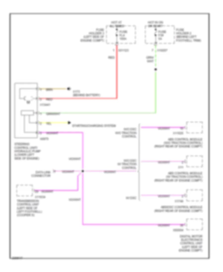
ELECTRONIC POWER STEERING
Electronic Power Steering Wiring Diagram for MINI Cooper S 2007
List of elements for Electronic Power Steering Wiring Diagram for MINI Cooper S 2007:
- Abs control module (w/ traction control) (right rear of engine compt)
- Abs control module (w/o traction control) (right rear of engine compt)
- Abs/dsc control module (right rear of engine compt)
- Data link connector
- Digital motor electronics control unit (left side of engine compt)
- Fuse f39 5a
- Fuse fl4 100a
- Fuse holder 2 (behind left footwell trim)
- Fuse holder 3 (left side of engine compt)
- Hot at all times
- Hot in on or start
- Red
- Starting/charging system
- Steering control unit/ hydraulic pump (lower left side of engine)
- Transmission control unit (left side of left footwell) (cooper s)
- W/ dsc
- W/o dsc w/ traction control
- W/o dsc w/o traction control
- X01123
- X10207
- X11
- X11525
- X11634
- X13441
- X173 (behind battery)
- X1746
- X60004
- X6975
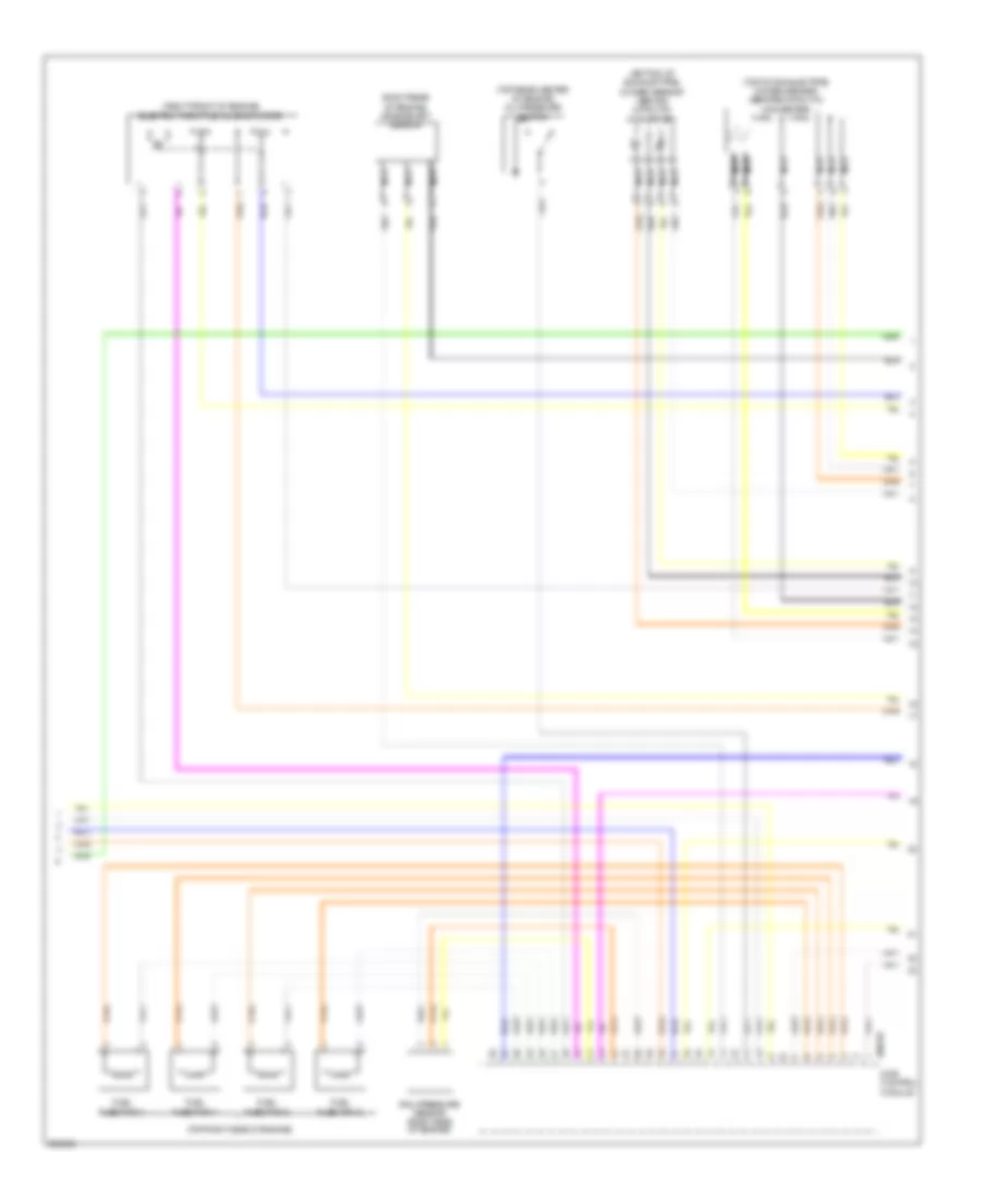
ENGINE PERFORMANCE
1.6L
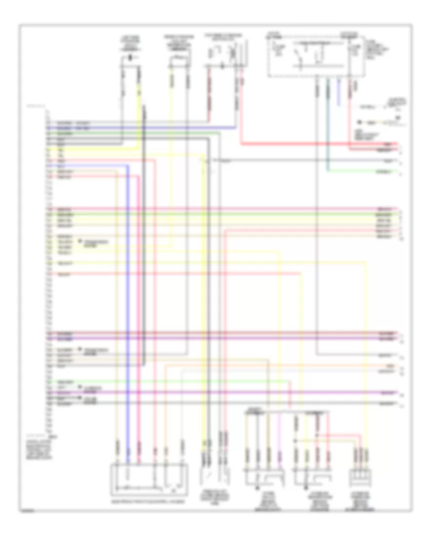
1.6L, Engine Performance Wiring Diagram (1 of 3) for MINI Cooper S 2007
List of elements for 1.6L, Engine Performance Wiring Diagram (1 of 3) for MINI Cooper S 2007:
- (left side of engine) knock sensor
- (rear of engine) coolant temperature sensor
- (top rear of engine) ignition coil
- Charging system
- Cooper s
- Cruise system
- Digital motor electronics control unit (left side of engine compt)
- Electric fuel pump
- Electronic throttle control housing
- Except cooper s
- Fuel pump relay
- Fuse f34 10a
- Fuse f37 20a
- Fuse holder 2 (behind left footwell trim)
- Hot at all times
- Hot in on or start
- Intake air pressure sensor (before supercharger)
- Intake air temperature sensor (left side of engine)
- Intake vacuum sensor (front of engine compt)
- Nca
- Precatalyst oxygen sensor (front exhaust pipe)
- Red
- Transmission system
- X10204
- X490 (below right rear seat)
- X6000
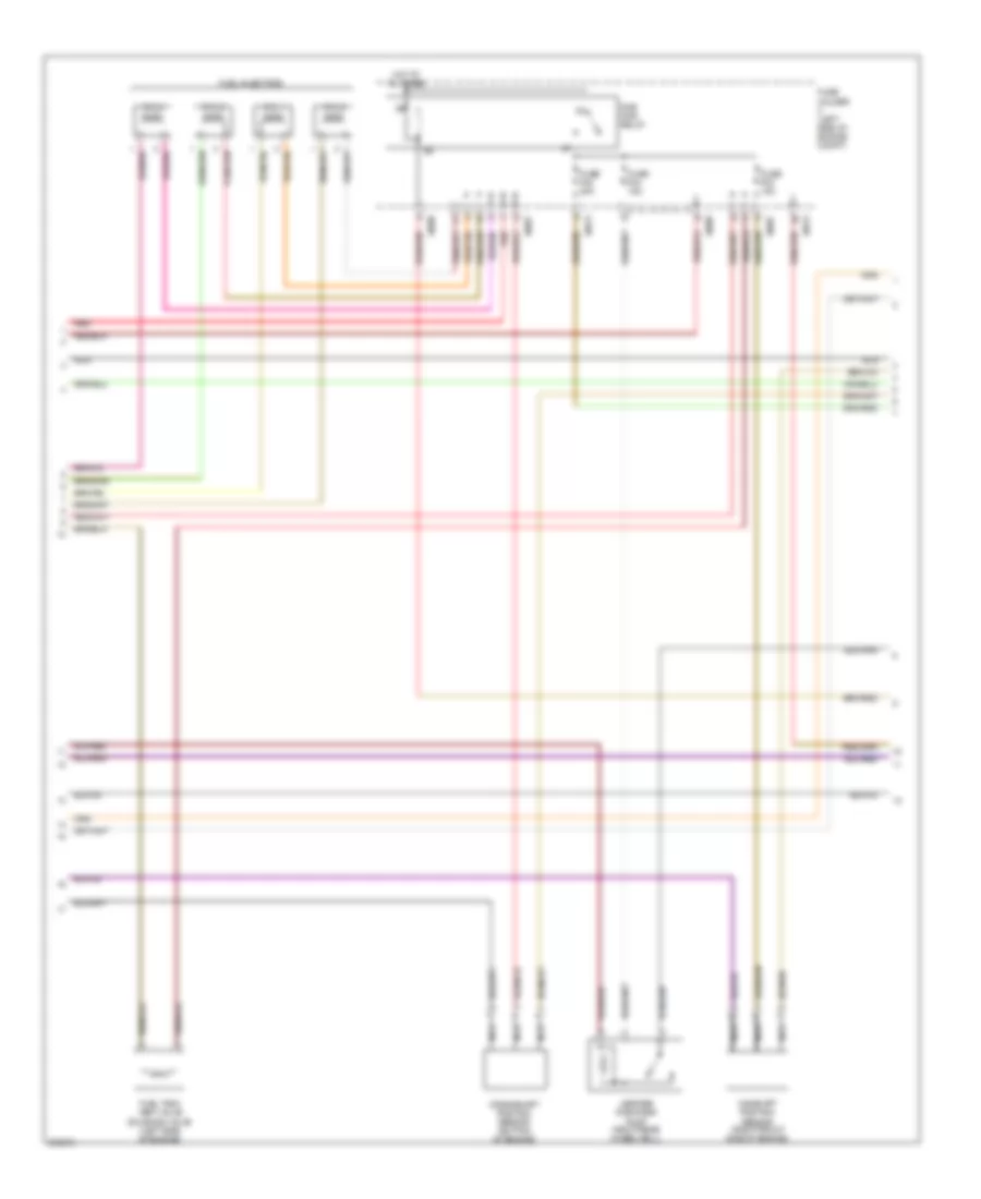
1.6L, Engine Performance Wiring Diagram (2 of 3) for MINI Cooper S 2007
List of elements for 1.6L, Engine Performance Wiring Diagram (2 of 3) for MINI Cooper S 2007:
- Camshaft position sensor (right front side of engine)
- Crankshaft position sensor (bottom of engine)
- Cyl 1
- Cyl 2
- Cyl 3
- Cyl 4
- Dme main relay
- Fuel injectors
- Fuel tank vent valve solenoid valve (left side of engine)
- Fuse f02 20a
- Fuse f03 15a
- Fuse f04 15a
- Fuse holder (left side of engine compt)
- Hot at all times
- Leakage diagnosis pump (right rear wheelwell)
- Nca
- Red
- X4009
- X4013
- X8687
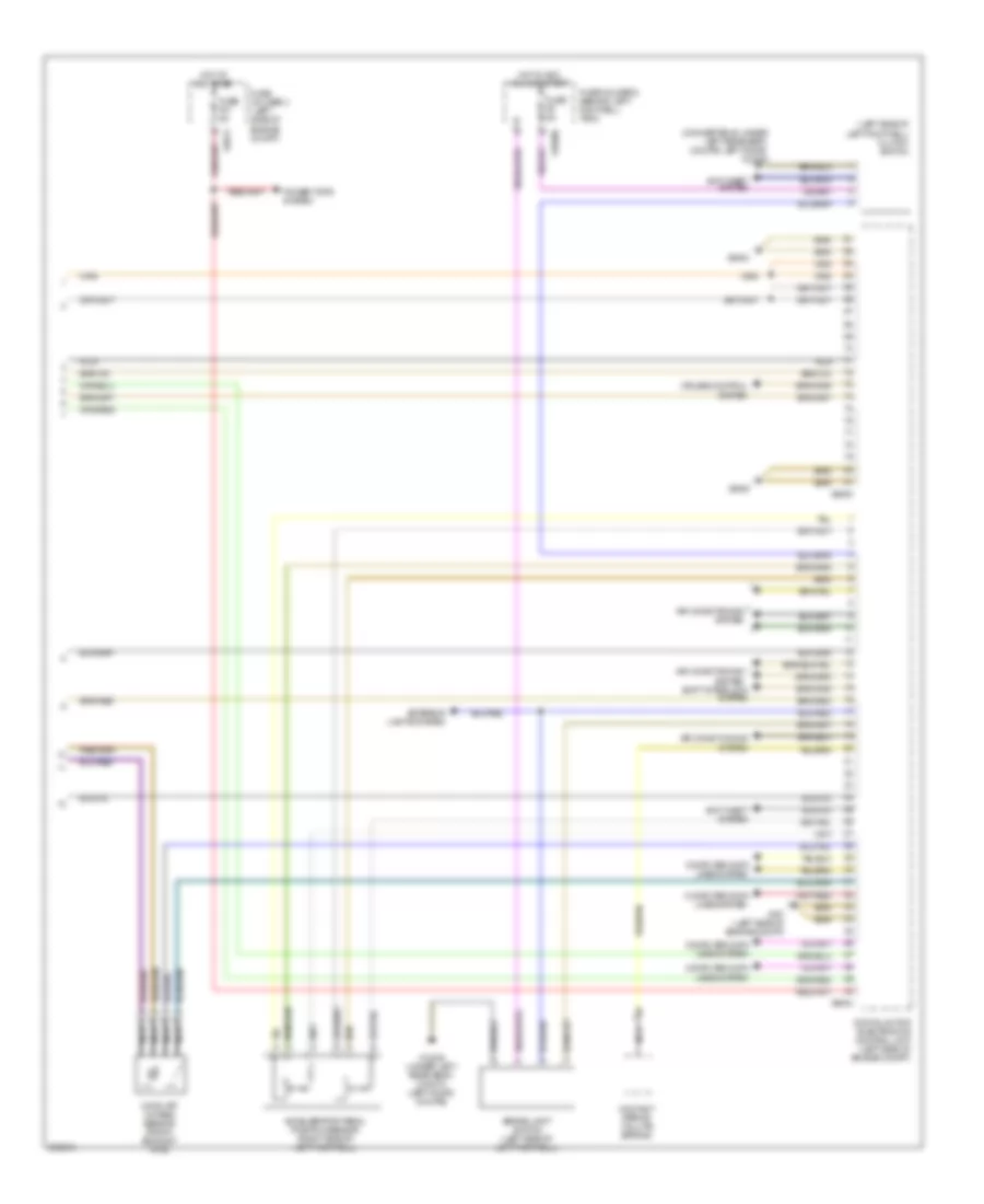
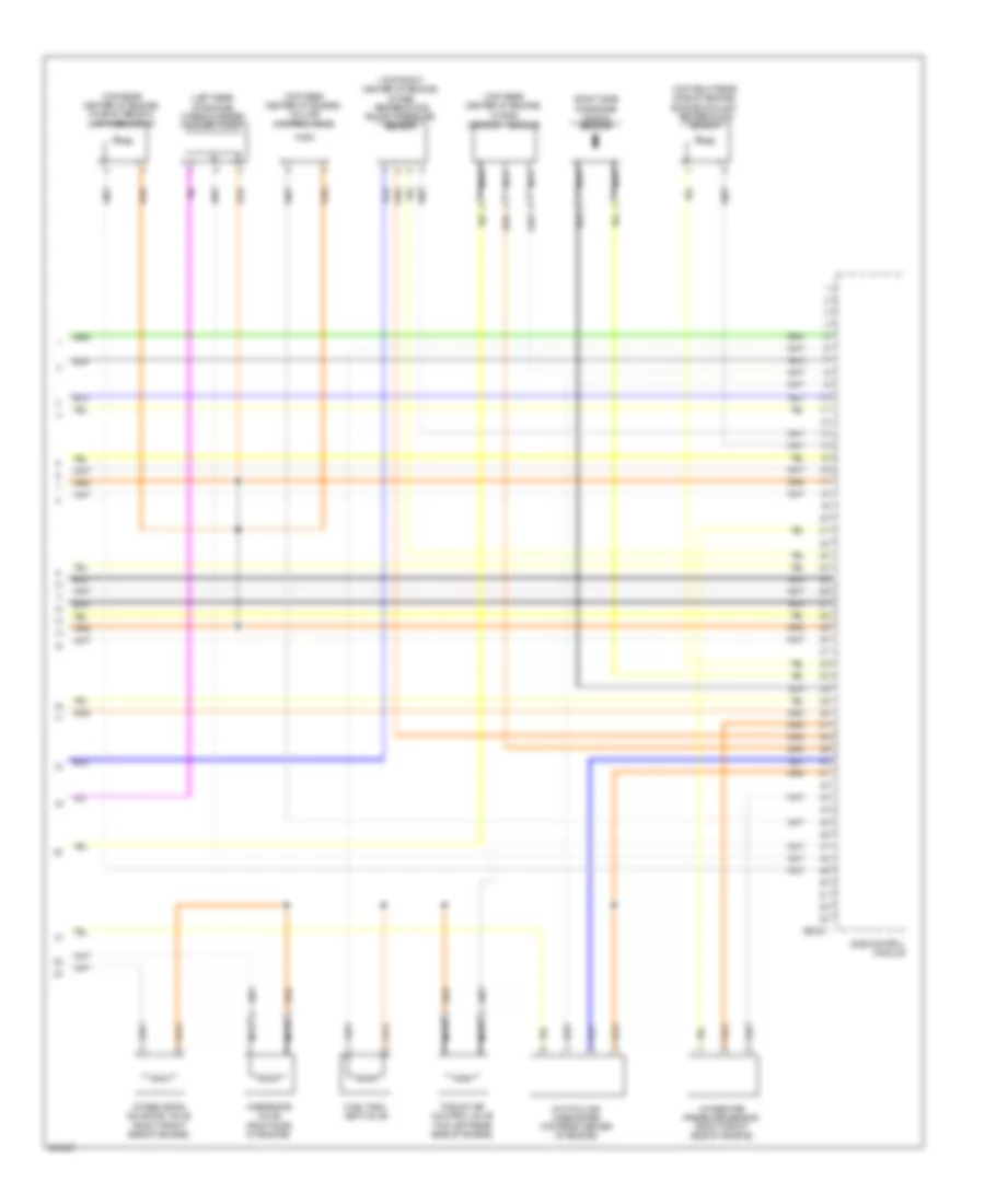
1.6L, Engine Performance Wiring Diagram (3 of 3) for MINI Cooper S 2007
List of elements for 1.6L, Engine Performance Wiring Diagram (3 of 3) for MINI Cooper S 2007:
- (convertible: under left rear seat) (coupe: left door) x13230
- (left side of left footwell) clutch switch
- Accelerator pedal position sensor (right side of left footwell)
- Air conditioning system
- Anti-theft system
- Brake light switch (left side of left footwell)
- Catalyst oxygen sensor (front exhaust pipe)
- Computer data lines system
- Contact spring (volute spring)
- Cruise control system
- Digital motor electronics control unit (left side of engine compt)
- Exterior lights system
- Fuse f01 5a
- Fuse f6 5a
- Fuse holder 2 (behind left footwell trim)
- Fuse holder 3 (left side of engine compt)
- Hot at all times
- Hot in acc, run or start
- Nca
- Power tops system
- Shift interlock system
- X10200
- X13230 (under left rear seat) (convt) (left door) (coupe)
- X167 (left side of engine compt)
- X4013
- X6000
- X6004
- X6454
1.6L TURBO
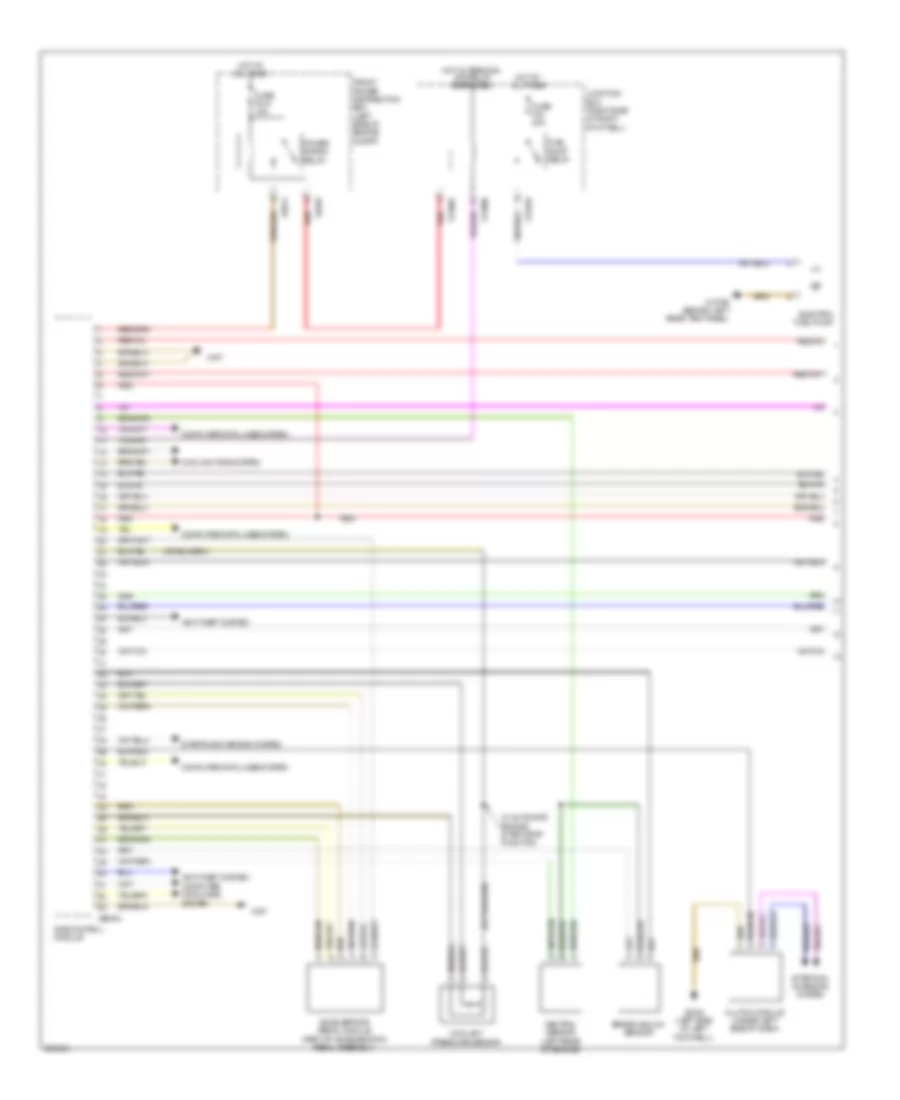
1.6L Turbo, Engine Performance Wiring Diagram (1 of 4) for MINI Cooper S 2007
List of elements for 1.6L Turbo, Engine Performance Wiring Diagram (1 of 4) for MINI Cooper S 2007:
- Accelerator pedal module (part of acceleration pedal assembly)
- Anti-theft system
- Brake vacuum sensor
- Clutch module (under left side of dash)
- Computer data lines system
- Coolant pressure sensor
- Cooling fans system
- Dme control module
- Electric fuel pump
- Front power distribution box (left side of engine compt)
- Fuel pump relay
- Fuse f010 15a
- Fuse f43 20a
- Hot at all times
- Hot w/ terminal 30g relay energized
- Junction box (right side of right footwell)
- Neutral sensor (left rear of engine)
- Power saving relay
- Red
- Starting/ charging system
- Starting/charging system
- W/ automatic engine start-stop function
- X11002
- X11008
- X11010
- X13795 (behind left rear trim panel)
- X167
- X2042 (left side of left footwell)
- X4010
- X4014
- X60004
1.6L Turbo, Engine Performance Wiring Diagram (2 of 4) for MINI Cooper S 2007
List of elements for 1.6L Turbo, Engine Performance Wiring Diagram (2 of 4) for MINI Cooper S 2007:
- (left front side of engine compt)
- (top of engine)
- Brake light switch (left side of left footwell)
- Cooling fans system
- Dme relay
- Engine breather heater 1 (right rear side of engine)
- Engine breather heating relay
- Exterior lights system
- Front power distribution box (left side of engine compt)
- Fuel injectors relay
- Fuel tank leakage diagnostic module (front of right rear wheel)
- Fuse box (right rear of engine compt)
- Fuse f01 5a
- Fuse f02 25a
- Fuse f03 20a
- Fuse f04 20a
- Fuse f05 5a
- Fuse f07 7.5a
- Fuse f68 40a
- Hot at all times
- Ignition coil 1
- Ignition coil 2
- Ignition coil 3
- Ignition coil 4
- Interference suppression capacitor (top right side of engine)
- Red
- X175
- X2042 (left side of left footwell)
- X4009
- X4010
- X4013
- X6401
- X64561 (top of engine)
1.6L Turbo, Engine Performance Wiring Diagram (3 of 4) for MINI Cooper S 2007
List of elements for 1.6L Turbo, Engine Performance Wiring Diagram (3 of 4) for MINI Cooper S 2007:
- (bottom of exhaust pipe) oxygen sensor (behind catalytic converter)
- (right front of engine) electric throttle valve actuator
- (right rear of engine) crankshaft sensor
- (top of exhaust pipe) oxygen sensor (before catalytic converter)
- (top rear center of engine) oil pressure switch
- (top right side of engine)
- Dme control module
- Fuel injection 1
- Fuel injection 2
- Fuel injection 3
- Fuel injection 4
- Nca
- Rail pressure sensor (right side of engine)
- X60232
1.6L Turbo, Engine Performance Wiring Diagram (4 of 4) for MINI Cooper S 2007
List of elements for 1.6L Turbo, Engine Performance Wiring Diagram (4 of 4) for MINI Cooper S 2007:
- (left rear of engine) turbocharger coolant pump
- (right side of engine) knock sensor
- (top front center of engine) intake temperature boost pressure sensor
- (top rear center of engine)
- (top rear center of engine) characteristic map thermostat
- (top rear center of engine) volume control valve
- (top right rear side of engine) engine coolant temperature sensor
- Dme control module
- Fuel tank vent valve
- Hot-film air mass meter (top rear center of engine)
- Intake camshaft sensor
- Intake pipe pressure sensor (right front side of engine)
- Intake vanos solenoid valve (right front side of engine)
- Nca
- Thrust air control valve (top left rear side of engine)
- Wastegate valve (right side of engine)
- X60231
EXTERIOR LIGHTS
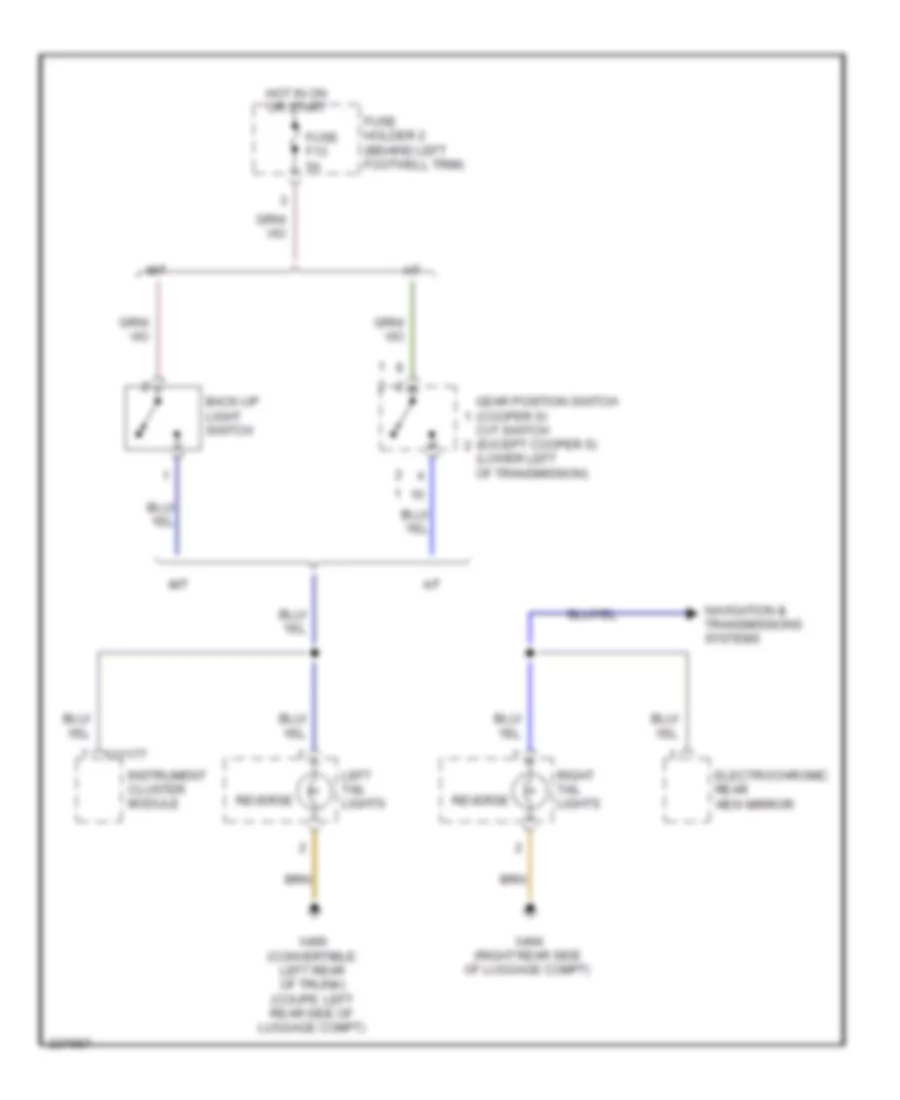
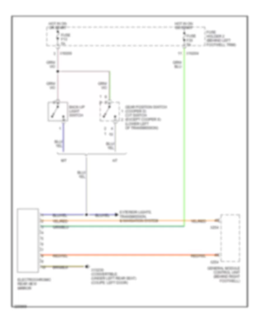
Back-up Lamps Wiring Diagram for MINI Cooper S 2007
List of elements for Back-up Lamps Wiring Diagram for MINI Cooper S 2007:
- (lower left of transmission)
- A/t
- Back-up light switch
- Cvt switch (except cooper s)
- Electrochromic rear view mirror
- Fuse f13 5a
- Fuse holder 2 (behind left footwell trim)
- Gear position switch (cooper s)
- Hot in on or start
- Instrument cluster module
- Left tail lights
- M/t
- Navigation & transmissions systems
- Reverse
- Right tail lights
- X11177
- X490 (convertible: left rear of trunk) (coupe: left rear side of luggage compt)
- X494 (right rear side of luggage compt)
Exterior Lamps Wiring Diagram (1 of 2) for MINI Cooper S 2007
List of elements for Exterior Lamps Wiring Diagram (1 of 2) for MINI Cooper S 2007:
- (convertible: under left rear seat) (coupe: left door)
- (right rear of luggage compt)
- Backup
- Brake
- Computer data lines system
- Convertible
- Exterior lights system (back-up lights circuit)
- Fuse 5a
- Fuse holder 2 (behind left footwell trim)
- Fuse holder 3 (left side of engine compt)
- Fuse link 12 50a
- Fuse link 8 50a
- General module control unit (behind right footwell)
- Hot at all times
- Hot in accy, run and start
- Hot in on or start
- Instrument cluster module
- Left front auxiliary flasher light
- Left front turn signal light
- Left parking light
- Left rear side marker light
- Left side marker light
- Left tail light
- License plate light
- Not used
- Park
- Switch panel
- Turn
- Turn signal/headlight dimmer switch
- X10200
- X10207
- X1108 (left door)
- X11175
- X11177
- X13230
- X151 (right side of right footwell)
- X175 (left side of engine compt)
- X253
- X254
- X255
- X332
- X4009
- X4010
- X490 (convertible: left rear of trunk coupe: left rear of luggage compt)
- X490 (convertible: left rear of trunk coupe: left rear side of luggage compt)
- X494
Exterior Lamps Wiring Diagram (2 of 2) for MINI Cooper S 2007
List of elements for Exterior Lamps Wiring Diagram (2 of 2) for MINI Cooper S 2007:
- Abs control module (w/ traction control)
- Abs control module (w/o traction control)
- Abs/dsc unit
- Backup
- Brake
- Brake light switch (left side of left footwell)
- Center brake light
- Digital motor electronics control unit (left side of engine compt)
- Exterior lights system (back-up lights circuit)
- Fuse 5a
- Fuse holder 2 (behind left footwell trim)
- Hot in accy, run and start
- Park
- Right front auxiliary flasher light
- Right front turn signal light
- Right parking light
- Right rear side marker light
- Right side marker light
- Right tail light
- Turn
- W/ dsc
- W/o dsc
- X10200
- X11
- X11525
- X13230 (convertible: under left rear seat coupe: left door)
- X165 (right side of engine compt)
- X1746
- X490 (convertible: left rear of trunk coupe: left rear side of luggage compt)
- X494 (right rear of luggage compt)
- X494 (right rear side of luggage compt)
- X60004
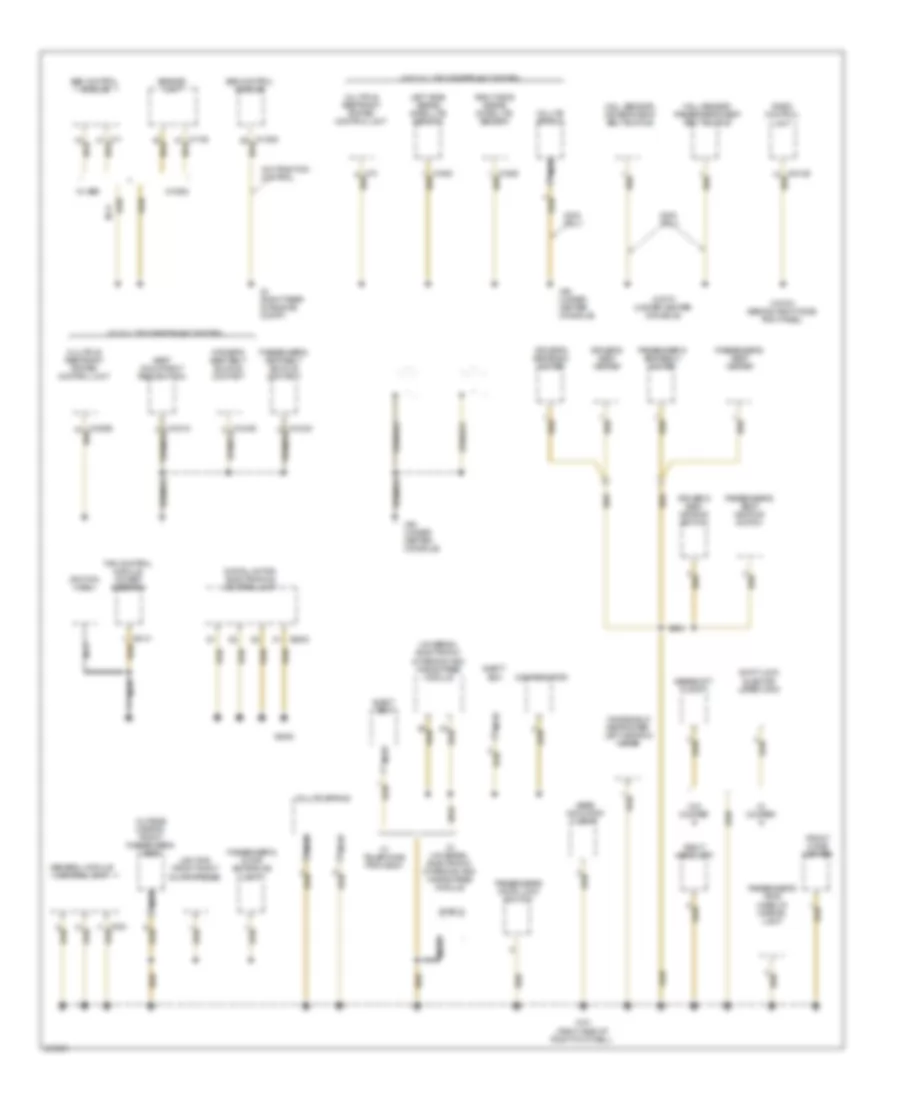
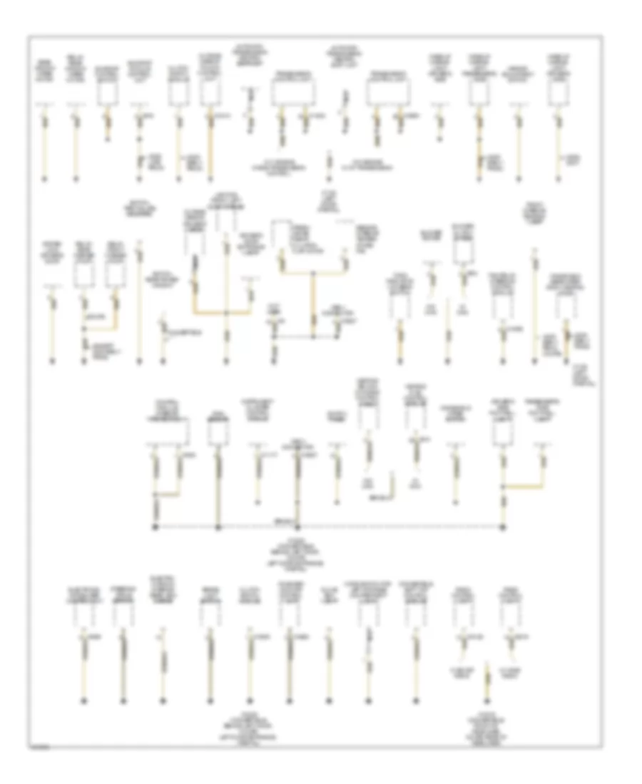
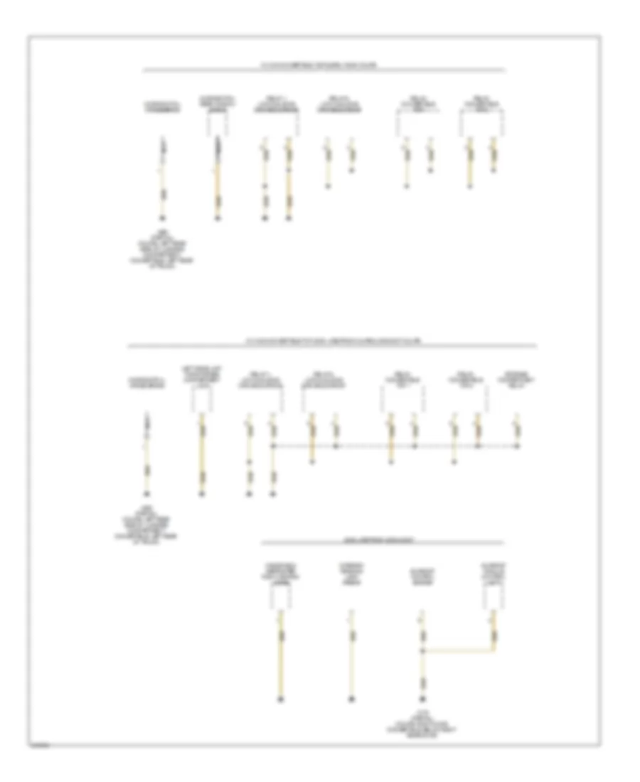
GROUND DISTRIBUTION
Ground Distribution Wiring Diagram (1 of 4) for MINI Cooper S 2007
List of elements for Ground Distribution Wiring Diagram (1 of 4) for MINI Cooper S 2007:
- (w/ multiple restraint system)
- (w/o multiple restraint system)
- Abs control module
- Abs/dsc unit
- Compensator
- Digital motor electronics control unit
- Driver's seat belt buckle contact
- Driver's seat heater
- Driver's seat heating switch
- Driver's seatback heater
- Eject box
- Fan control module, power steering
- Front cigar lighter
- Gear indicator light
- Gearshift lock
- General module control unit
- Hall sensor, driver's seat belt buckle
- Hall sensor, passenger's seat belt buckle
- Ignition coil
- Left side airbag satellite sensor
- Lighting, front right door opener
- Multiple restraint system control unit
- Nca
- Only
- Outside mirror, front passenger's side
- Passenger's door entrance light
- Passenger's seat belt buckle contact
- Passenger's seat heater
- Passenger's seat heating switch
- Passenger's seatback heater
- Passenger's side make-up mirror light
- Passengers door lock switch
- Radio control unit
- Right headlight
- Right side airbag satellite sensor
- Seat occupancy recognition
- Shield
- Shift lock elector level lock
- Universal electronic charging and hands-free module
- Volute spring
- W/ abs
- W/ cooper s
- W/ dsc
- W/ telephone provision
- W/ universal electronic charging and hands-free module
- W/o cooper s
- W/o traction control
- Windshield defroster, left heating zone
- X151 (right side of right footwell)
- X18170 (under center console)
- X18723 (behind right side trim panel)
- X4 (right rear of engine compt)
- X46 (under center console)
- X6000
- X6454
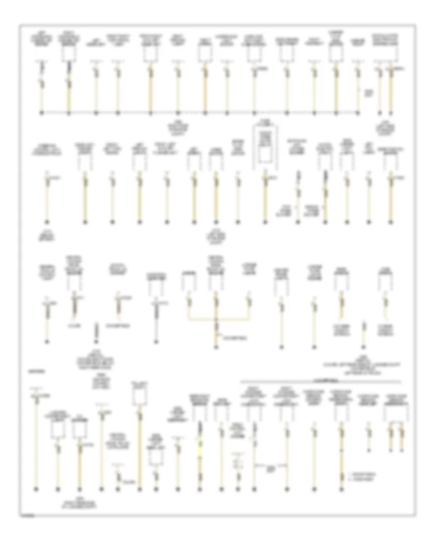
Ground Distribution Wiring Diagram (2 of 4) for MINI Cooper S 2007
List of elements for Ground Distribution Wiring Diagram (2 of 4) for MINI Cooper S 2007:
- 2006,
- Amplifier
- Boost radio
- Brake fluid level switch
- Cd changer
- Center brake light
- Central locking drive, trunk lid/ tailgate
- Central locking drive, trunk lid/tailgate
- Compt)
- Convertible
- Coupe
- Digital motor electronics control unit
- Diode
- Front left auxiliary flasher unit
- Front left turn signal
- Front right auxiliary flash unit
- Front right turn signal lamp
- Fuse holder iii
- Gear position switch
- General module control unit
- Headlight washer pump
- Horn for anti-theft alarm system
- Left fog light
- Left headlight
- Left horn
- Left parking light
- Left windshield washer jet heater
- License plate lights
- License plate lights (coupe)
- Luggage compartment light
- Microwave sensor, driver's door
- Microwave sensor, passenger's door
- Microwave sensor, rear left
- Microwave sensor, rear right
- Motor, electric fan i
- Navigation computer
- Nca
- On/off wiper motor relay
- Park distance control unit (pdc)
- Radio control unit (coupe)
- Rear fog light
- Rear right brake pad sensor
- Rear window
- Right fog right
- Right horn
- Right parking light
- Right storage compartment lock driver's unit
- Right storage compartment lock microswitch
- Right windshield washer jet heater
- Side marker light, left
- Side marker light, rear left
- Side marker light, rear right
- Side marker light, right
- Single- stage blower
- Steering control unit/ hydraulic pump
- Switch, trunk lid contact
- Switching unit, 2-stage blower
- Taillight, right
- Two- stage blower
- Underhood light switch
- W/ rear window antenna
- W/o rear window antenna
- Washer fluid level switch
- Washer pump
- Wave radio
- Wave trap 2
- Wiper motor
- X165 (right side of engine
- X167 (left side of engine compt)
- X173 (behind battery)
- X175 (left side of engine compt)
- X179 (partial) (coupe: right door, convertible: below right rear door)
- X490 (partial) (coupe: left rear side of luggage compt, convertible: left rear of trunk)
- X494 (right rear side of luggage compt)
Ground Distribution Wiring Diagram (3 of 4) for MINI Cooper S 2007
List of elements for Ground Distribution Wiring Diagram (3 of 4) for MINI Cooper S 2007:
- (2005 early prod coupe)
- (2005 early prod)
- (2005 late prod)
- (2006, 2007)
- (except 2005 early prod)
- Automatic transmission central shift unit
- Blower motor
- Blower output stage
- Brake light switch
- Clutch switch module
- Control module, interior protection i
- Convertible
- Convertible soft top control module
- Coupe
- Driver's door entrance light
- Driver's side footwell light
- Electro- chromic interior rear-view mirror
- Electronic immobilizer control unit
- Fan relay, steering control module
- Fresh air/air recir- culation flap motor
- Front interior reading lamp
- Glove box light
- Heating & a/c control module
- Heating/ air con- ditioning control panel
- Instrument cluster control module
- Lighting, front left door opener
- Make-up mirror light, driver's side
- Make-up mirror light, passenger's side
- Microswitch for left storage compartment lock
- Mirror adjustment switch
- Nca
- Not used
- Obd ii connector
- On-board monitor control unit
- Outside mirror fold-in control unit
- Outside mirror, driver's side
- Passenger's side footwell light
- Radio control unit
- Rain sensor
- Rear window wiper motor
- Relay, front washer pump
- Relay, rear washer pump
- Relay, rear window wiper motor
- Sensor, interior temper- ature/ fan
- Steering angle sensor
- Sunroof control switch
- Sunroof module control unit
- Switch panel
- Switch, rear power window
- Switch, tire failure indicator
- System lock, driver's door
- Transmission control unit
- Turn indicator/ low beam switch
- W/ boost radio
- W/ ihka
- W/ wave radio
- W/o ihka
- W10 engine w/ a/t transmission
- W11 engine w/ egs transmission control
- Windshield defroster, right heating zone
- Windshield wiper switch
- X1108 (left door) (partial)
- X13016 (convertible: front of headliner, coupe: rear of headliner)
- X13230 (convertible: behind left door, coupe: left door entrance) (partial)
Ground Distribution Wiring Diagram (4 of 4) for MINI Cooper S 2007
List of elements for Ground Distribution Wiring Diagram (4 of 4) for MINI Cooper S 2007:
- 2005 late prod, 2006 & 2007
- Interior/ reading lamp, front
- Left drive unit for storage compartment lock
- Microswitch, cross brace
- Microswitch, rear window shelf
- Nca
- Relay 1, lock & sliding canvas sunroof
- Relay 2, lock & sliding canvas sunroof
- Relay, convertible top 1
- Relay, convertible top 2
- Storage compartment relay
- Sunroof control switch
- Sunroof module control unit
- W/ cvm convertible top & early 2005 coupe
- W/ cvm2 convertible top, 2005 late prod coupe & 2006-2007 coupe
- Windshield defroster right heating zone
- X179 (partial) (coupe: right door, convertible: below right rear door)
- X490 (partial) (coupe: left rear side of luggage compartment, convertible: left rear of trunk)
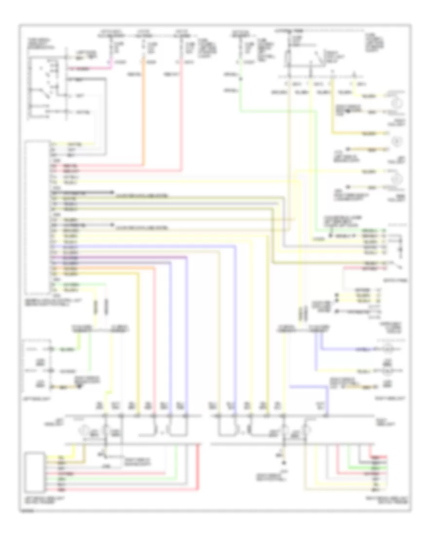
HEADLIGHTS
Headlamps Wiring Diagram for MINI Cooper S 2007
List of elements for Headlamps Wiring Diagram for MINI Cooper S 2007:
- (convertible: under left rear seat) (coupe: left door)
- (left door) x1108
- (left side of engine compt)
- (right rear side of luggage compt)
- (right side of engine compt)
- (right side of engine compt) x165
- (right side of right footwell)
- (right side of right footwell) x151
- All times
- Computer data lines system
- Front fog light relay
- Fuse f010 15a
- Fuse f40 5a
- Fuse f8 5a
- Fuse fl12 50a
- Fuse fl8 50a
- Fuse holder 2 (behind left footwell trim)
- Fuse holder 3 (left side of engine compt)
- General module control unit (behind right footwell)
- High beam
- Hot at
- Hot at all times
- Hot in accy,
- Hot in on or start
- Instrument cluster module
- Left fog light
- Left headlight
- Left xenon headlight ignition trigger
- Low beam
- Rear fog light
- Red
- Right fog light
- Right headlight
- Right xenon headlight ignition trigger
- Run and start
- Switch panel
- Turn signal/ headlight dimmer switch
- W/ halogen headlight
- W/ xenon headlight
- X10200
- X10207
- X11175
- X11177
- X13230
- X151
- X165
- X175
- X254
- X255
- X332
- X4009
- X4010
- X4013
- X4014
- X494
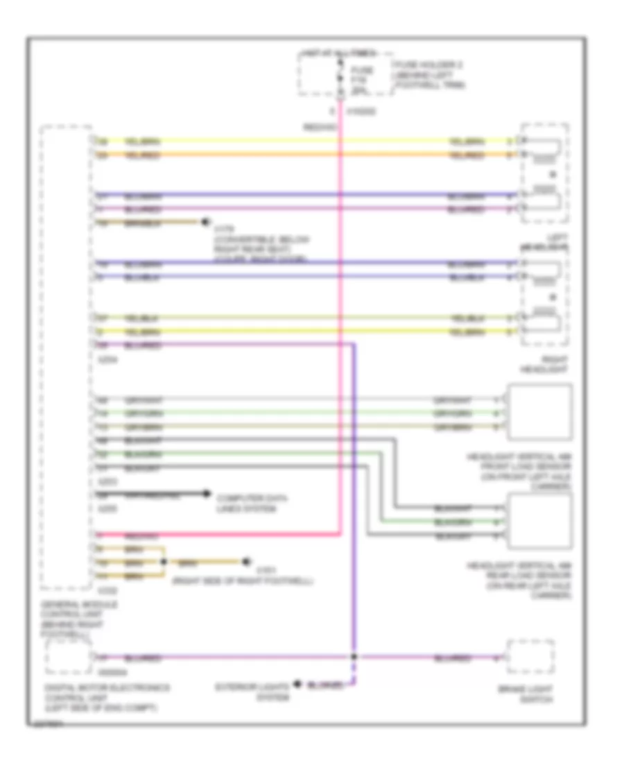
Headlamps Leveling Wiring Diagram for MINI Cooper S 2007
List of elements for Headlamps Leveling Wiring Diagram for MINI Cooper S 2007:
- (right side of right footwell)
- Brake light switch
- Computer data lines system
- Digital motor electronics control unit (left side of eng compt)
- Exterior lights system
- Fuse f19 30a
- Fuse holder 2 (behind left footwell trim)
- General module control unit (behind right footwell)
- Headlight vertical aim front load sensor (on front left axle carrier)
- Headlight vertical aim rear load sensor (on rear left axle carrier)
- Hot at all times
- Left headlight
- Right headlight
- X10202
- X151
- X179 (convertible: below right rear seat) (coupe: right door)
- X253
- X254
- X255
- X332
- X60004
HORN
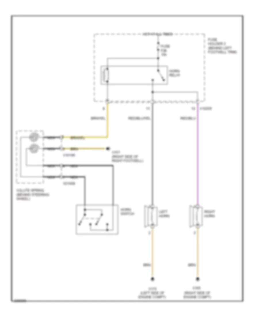
Horn Wiring Diagram for MINI Cooper S 2007
List of elements for Horn Wiring Diagram for MINI Cooper S 2007:
- (right side of engine compt)
- Fuse f28 15a
- Fuse holder 2 (behind left footwell trim)
- Horn relay
- Horn switch
- Hot at all times
- Left horn
- Nca
- Right horn
- Volute spring (behind steering wheel)
- X01008
- X10195
- X10205
- X151 (right side of right footwell)
- X165
- X175 (left side of engine compt)
INSTRUMENT CLUSTER
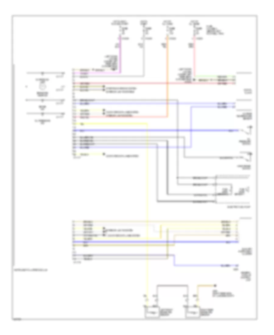
Instrument Cluster Wiring Diagram for MINI Cooper S 2007
List of elements for Instrument Cluster Wiring Diagram for MINI Cooper S 2007:
- (left door) (coupe) (under left rear seat) (convertible) x13230
- Auxiliary instrument cluster
- Brake ind
- Brake pad wear ind
- Charge ind lamp
- Computer data lines system
- Digital clock
- Electric fuel pump
- Exterior lights system
- Exterior lights systems
- Fuel level sensor 1
- Fuel level sensor 2
- Fuse fuse f21 10a
- Fuse fuse f3 5a
- Fuse fuse f5 5a
- Fuse fuse f9 5a
- Fuse holder 2 (behind left footwell trim)
- General module control unit
- Hand brake switch
- Hot at all times
- Hot in accy, run and start
- Hot in start
- Instrument cluster module
- Interior lights system
- Left front brake pad sensor
- Oil pressure ind
- Oil pressure switch
- Outside temperature sensor
- Right rear brake pad sensor
- Starting/charging system
- X10200
- X10202
- X10206
- X11175
- X11177
- X255
- X494 (right rear side of luggage compt)
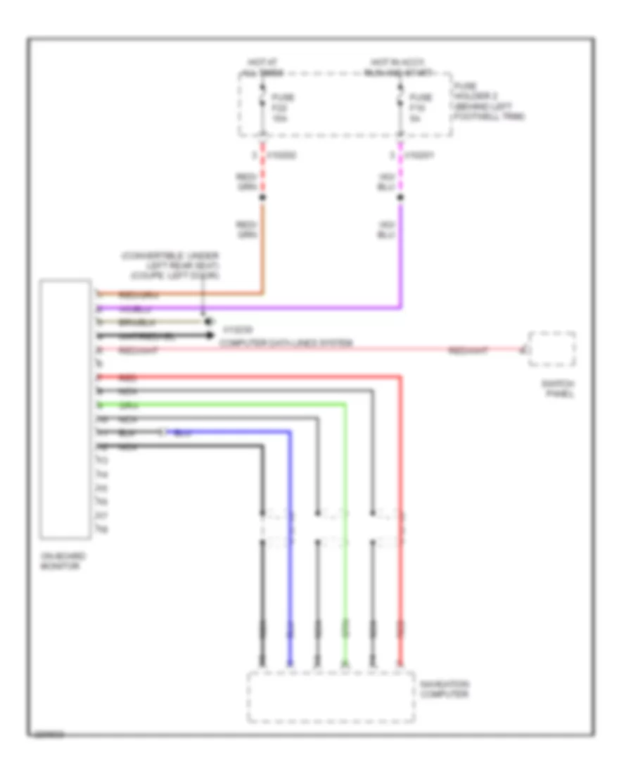
On-Board Computer Wiring Diagram for MINI Cooper S 2007
List of elements for On-Board Computer Wiring Diagram for MINI Cooper S 2007:
- (convertible: under left rear seat) (coupe: left door)
- Computer data lines system
- Fuse f10 5a
- Fuse f22 15a
- Fuse holder 2 (behind left footwell trim)
- Hot at all times
- Hot in accy, run and start
- Navigation computer
- Nca
- On-board monitor
- Red
- Switch panel
- X10201
- X10202
- X13230
INTERIOR LIGHTS
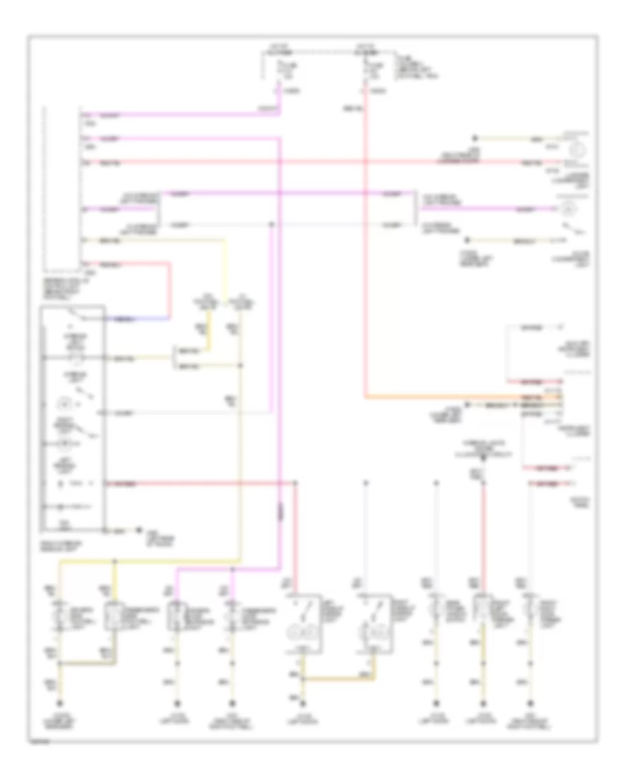
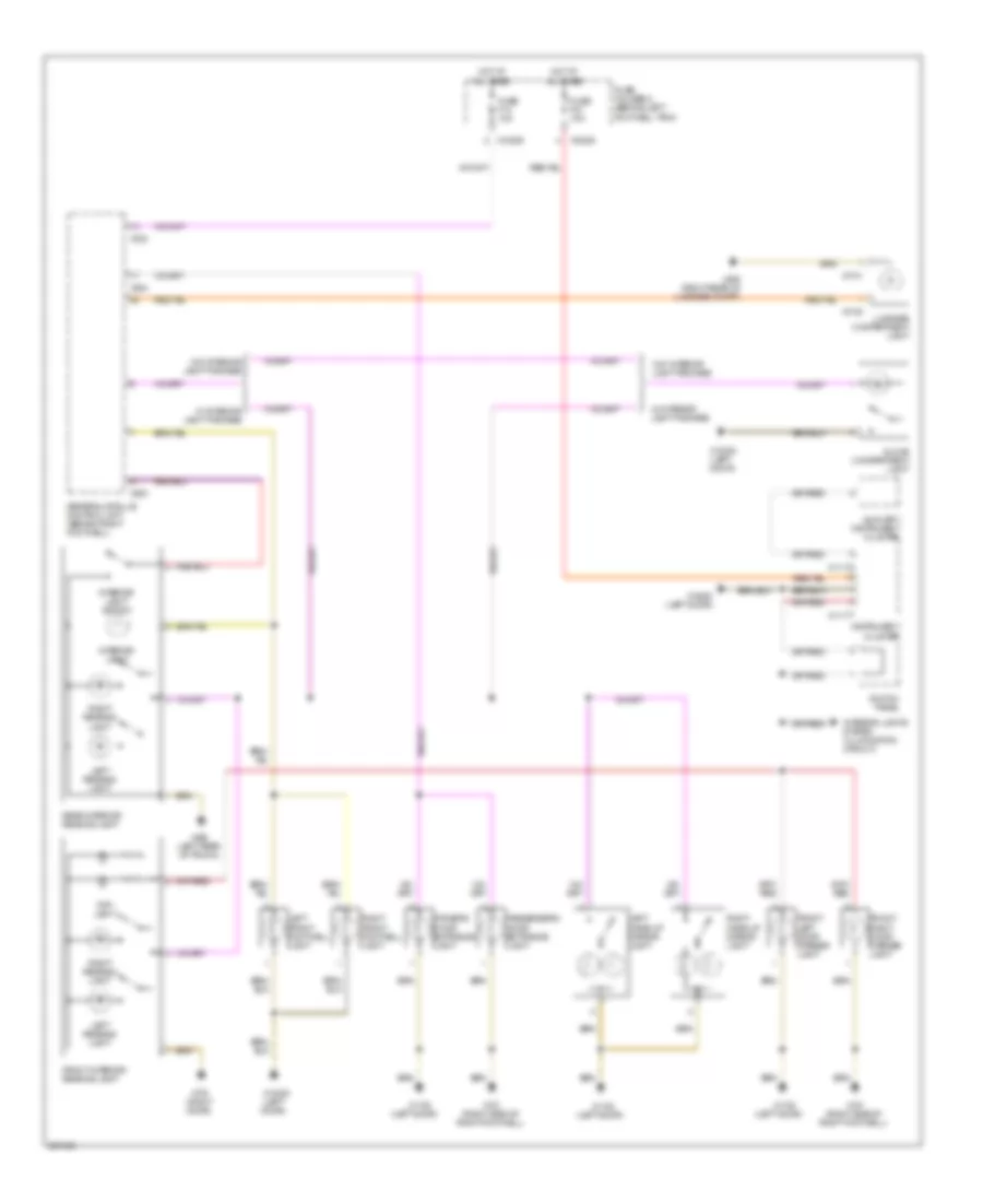
Courtesy Lamps Wiring Diagram, Convertible for MINI Cooper S 2007
List of elements for Courtesy Lamps Wiring Diagram, Convertible for MINI Cooper S 2007:
- (left door)
- (under left rear seat)
- Auxiliary instrument cluster
- Driver's door entrance light
- Driver's side footwell light
- Front interior/ reading lamp
- Front left door opener light
- Front right door opener light
- Fuse f14 10a
- Fuse f21 10a
- Fuse holder 2 (behind left footwell trim)
- General module control unit (behind right footwell)
- Glove compartment light
- Hot at all times
- Instrument cluster
- Interior light
- Interior light switch
- Interior lights system (illumination circuit)
- Left make-up mirror light
- Left reading light
- Luggage compartment light
- Passenger's door entrance light
- Passenger's side footwell light
- Rear power window switch
- Right make-up mirror light
- Right reading light
- Switch panel
- Top light
- W/ footwell lights
- W/ interior light package
- W/o footwell lights
- W/o interior light package
- X10202
- X10206
- X1108
- X11175
- X11177
- X13230
- X13230 (under left rear seat)
- X151 (right side of right footwell)
- X1740
- X1741
- X253
- X254
- X332
- X490 (left rear of trunk)
- X494 (right rear of luggage compt)
Courtesy Lamps Wiring Diagram, Except Convertible for MINI Cooper S 2007
List of elements for Courtesy Lamps Wiring Diagram, Except Convertible for MINI Cooper S 2007:
- (left door)
- Auxiliary instrument cluster
- Driver's door entrance light
- Front interior/ reading lamp
- Front left door opener light
- Front right door opener light
- Fuse f14 10a
- Fuse f21 10a
- Fuse holder 2 (behind left footwell trim)
- General module control unit (behind right footwell)
- Glove compartment light
- Hot at all times
- Instrument cluster
- Interior light
- Interior light switch
- Interior lights system (illumination circuit)
- Left front footwell light
- Left make-up mirror light
- Left reading light
- Luggage compartment light
- Passenger's door entrance light
- Rear interior/ reading lamp
- Right front footwell light
- Right make-up mirror light
- Right reading light
- Switch panel
- Top- light
- W/ interior light package
- W/o interior light package
- X10202
- X10206
- X1108
- X11175
- X11177
- X13230
- X13230 (left door)
- X151 (right side of right footwell)
- X1740
- X1741
- X179 (right door)
- X253
- X254
- X332
- X490 (left rear of trunk)
- X494 (right rear of luggage compt)
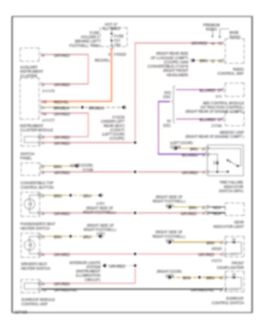
Instrument Illumination Wiring Diagram for MINI Cooper S 2007
List of elements for Instrument Illumination Wiring Diagram for MINI Cooper S 2007:
- (left door) x1108
- (right door) x179
- (right rear side of luggage compt) (coupe) x494 (convertible) x13016 (right front headliner)
- (right side of right footwell) x151
- Abs control module (w/ traction control) (right rear of engine compt.)
- Abs/dsc unit (right rear of engine compt.)
- Auxiliary instrument cluster
- Base radio
- Convertible top control button
- Driver's seat heater switch
- Front cigar lighter
- Fuse f21 10a
- Fuse holder 2 (behind left footwell trim)
- Gear indicator light
- Hot at all times
- Instrument cluster module
- Interior lights system (instrument illumination circuit)
- Nca
- Passenger's seat heater switch
- Premium radio
- Radio control unit
- Sunroof control switch
- Sunroof module control unit
- Switch panel
- Tire failure indicator switch (rpa)
- W/ dsc
- W/o dsc
- X10202
- X11
- X11175
- X11177
- X1213
- X13230 (under left rear seat) (convt) (left door) (coupe)
- X151 (right side of right footwell)
- X1746
- X9320
NAVIGATION
Navigation Wiring Diagram for MINI Cooper S 2007
List of elements for Navigation Wiring Diagram for MINI Cooper S 2007:
- (convertible: under left rear seat) (coupe: left door)
- (right rear of engine compt)
- Abs control module
- Abs control module (right rear of engine compt)
- Abs/dsc control module
- Amplifier (below passenger's seat) (convertible) (right side of luggage compt) (coupe)
- Computer data lines system
- Exterior lights, mirrors, transmissions systems
- Fuse f10 5a
- Fuse f22 15a
- Fuse holder 2 (behind left footwell trim)
- Gps antenna
- Hot at all times
- Hot in accy run and start
- Mirrors system
- Navigation computer (under right front seat) (coupe) (under left front seat) (convertible)
- Nca
- On-board monitor
- Radio control unit
- Red
- Switch panel
- W/ dsc
- W/ premium radio
- W/o dsc & w/ traction control
- W/o dsc & w/o traction control
- W/o premium radio
- X10201
- X10202
- X10266
- X11
- X11525
- X1312
- X1313
- X13230
- X1532
- X1746
- X179 (convertible: below right rear seat) (coupe: right door)
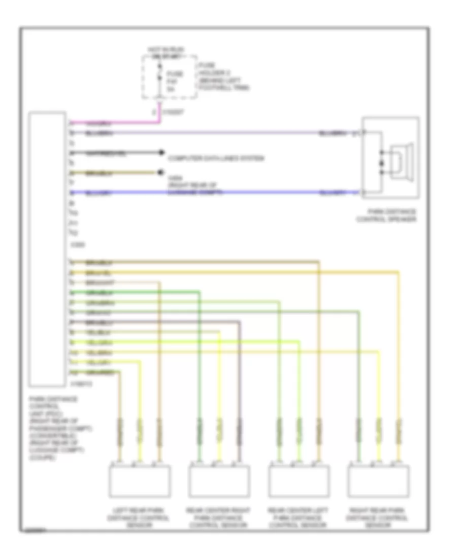
Parking Assistant Wiring Diagram for MINI Cooper S 2007
List of elements for Parking Assistant Wiring Diagram for MINI Cooper S 2007:
- Computer data lines system
- Fuse f41 5a
- Fuse holder 2 (behind left footwell trim)
- Hot in run or start
- Left rear park distance control sensor
- Park distance control speaker
- Park distance control unit (pdc) (right rear of passenger compt) (convertible) (right rear of luggage compt) (coupe)
- Rear center left park distance control sensor
- Rear center right park distance control sensor
- Right rear park distance control sensor
- X10207
- X18013
- X300
- X494 (right rear of luggage compt)
POWER DISTRIBUTION
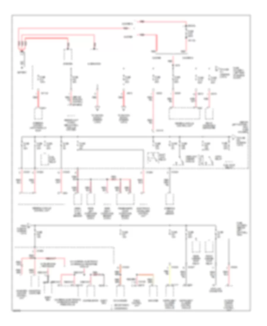
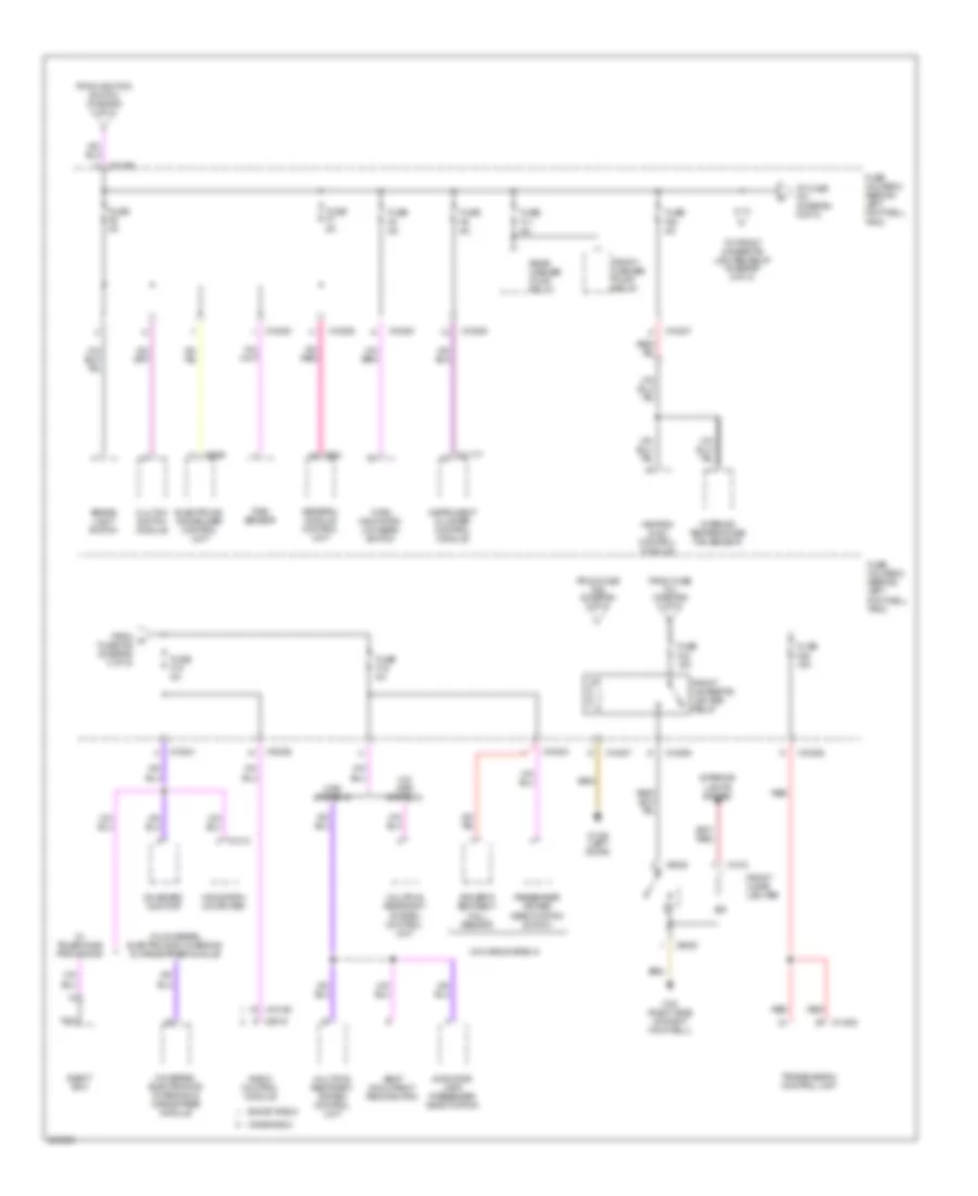
Power Distribution Wiring Diagram (1 of 5) for MINI Cooper S 2007
List of elements for Power Distribution Wiring Diagram (1 of 5) for MINI Cooper S 2007:
- (behind left footwell trim) fuse holder 2
- (boost radio)
- (others)
- (wave radio)
- Abs/dsc unit (w dsc) abs control module (w/o dsc)
- Alternator
- Amplifier
- Battery
- Cd changer
- Compensator
- Cooper
- Cooper s
- Data link connector
- Eject box
- Electronic immobilizer control unit
- From d fuse f20 (diagram 1 of 5)
- Front washer pump relay
- Fuel pump relay
- Fuel pump relay 1
- Fuse f1 30a
- Fuse f100 250a
- Fuse f19 30a
- Fuse f2 5a
- Fuse f20 20a
- Fuse f21 10a
- Fuse f22 15a
- Fuse f23 20a
- Fuse f24 5a
- Fuse f25 30a
- Fuse f26 10a
- Fuse f27 15a
- Fuse f28 15a
- Fuse f3 5a
- Fuse f37 20a
- Fuse f4 5a
- Fuse fl10 50a
- Fuse fl12 50a
- Fuse fl2 50a
- Fuse fl4 100a
- Fuse fl6 40a
- Fuse fl7 50a
- Fuse fl8 50a
- Fuse holder 2 (behind left footwell trim)
- Fuse holder 3 (left side of engine compt)
- General module control unit
- Headlight washer module
- Horn relay
- Instrument cluster control module
- Navigation computer
- Nca
- On-board monitor control unit
- Outside mirror fold-in control unit
- Passenger's door microwave sensor (conv)
- Radio control unit
- Rear left microwave sensor (conv)
- Rear right microwave sensor (conv)
- Rear washer pump relay
- Red
- Relay, windshield defroster
- Shift lock relay
- Siren w/ tilt alarm sensor
- Starter
- Steering angle sensor
- Steering control unit/hydraulic pump
- To fuse f22 (diagram 1 of 5)
- To fuse fl1 (diagram 2 of 5)
- To ignition switch (diagram 4 of 5)
- Traction control)
- Universal electronics charging & hands- free module
- W/ telephone provisions
- W/ universal electronic charging & hands-free module
- X01121
- X01122
- X01123
- X10178
- X10200
- X10201
- X10202
- X10205
- X10207
- X11177
- X13441
- X14133
- X18126
- X2519
- X254
- X332
- X4008
- X4009
- X4010
- X4015
- X819
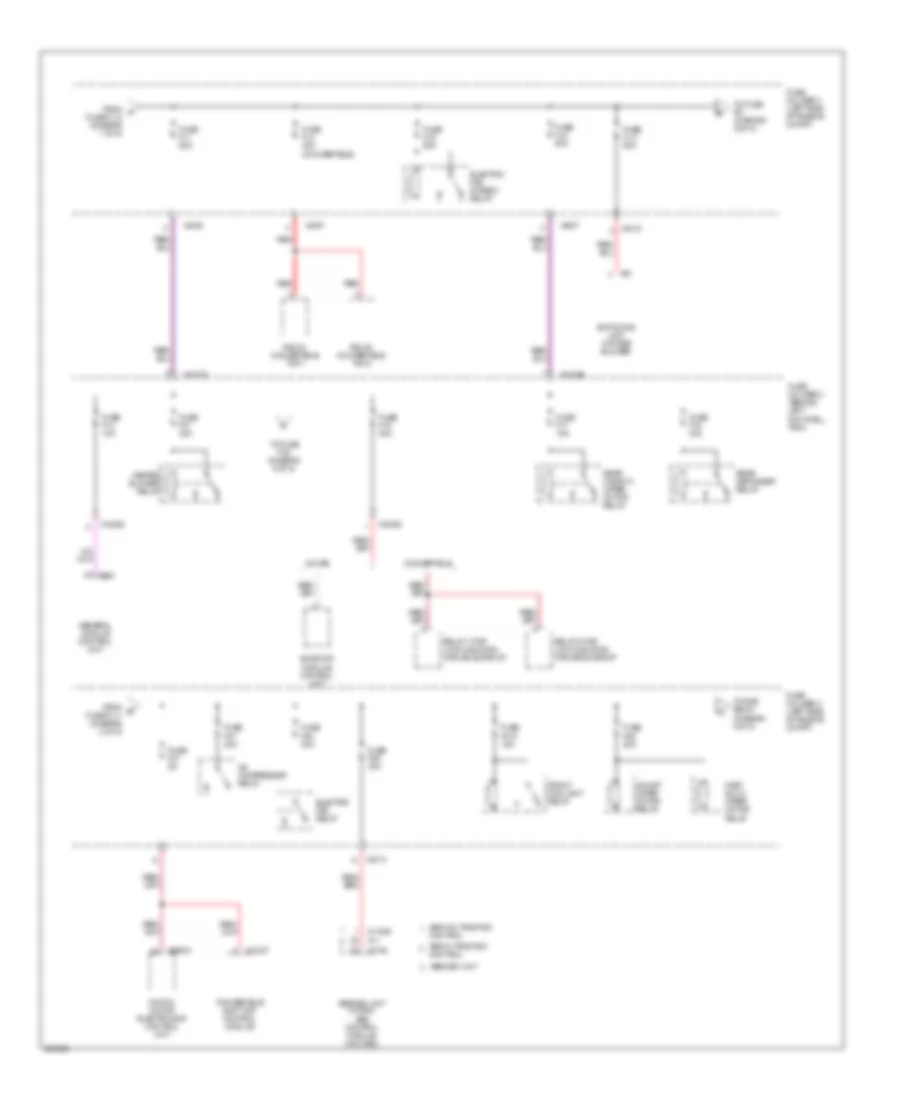
Power Distribution Wiring Diagram (2 of 5) for MINI Cooper S 2007
List of elements for Power Distribution Wiring Diagram (2 of 5) for MINI Cooper S 2007:
- A/c compressor relay
- Abs w/ traction
- Abs w/o traction
- Abs/dsc unit
- Abs/dsc unit (w dsc) abs control module (w/o dsc)
- Control
- Convertible
- Convertible soft top control module
- Coupe
- Digital motor electronics control unit
- Electric fan relay
- Electric fan stage 2 relay
- Fast/ slow wiper motor relay
- From a fuse fl12 (diagram 1 of 5)
- From e fuse fl11 (diagram 2 of 5)
- Front fog light relay
- Fuse f01 5a
- Fuse f010 15a
- Fuse f06 30a
- Fuse f07 30a
- Fuse f08 30a
- Fuse f09 20a
- Fuse f14 10a
- Fuse f15 20a
- Fuse f16 30a
- Fuse f17 15a
- Fuse f31 30a
- Fuse fl1 50a
- Fuse fl11 50a
- Fuse fl3 40a (convertible)
- Fuse fl5 50a
- Fuse fl9 50a
- Fuse holder 2 (behind left footwell trim)
- Fuse holder 3 (left side of engine compt)
- General module control unit
- Heater blower relay
- On/off wiper motor relay
- Rear defogger relay
- Rear window wiper motor relay
- Red
- Relay 1 for lock & sliding canvas sunroof
- Relay 2 for lock & sliding canvas sunroof
- Relay, convertible top 1
- Relay, convertible top 2
- Sunroof module control unit
- Switching unit, 2-stage blower
- To dme relay (diagram 3 of 5)
- To fuse f01 (diagram 2 of 5)
- To fuse f32 (diagram 5 of 5)
- X10178
- X10199
- X10206
- X11
- X11525
- X13037
- X1746
- X332
- X4007
- X4008
- X4013
- X4015
- X53
- X60004
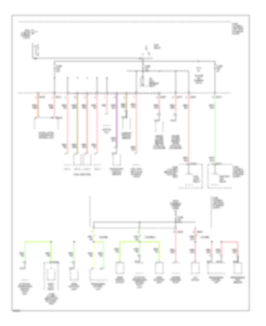
Power Distribution Wiring Diagram (3 of 5) for MINI Cooper S 2007
List of elements for Power Distribution Wiring Diagram (3 of 5) for MINI Cooper S 2007:
- (diagram 2 of 5 )
- A/c com- pressor relay
- Automatic transmission central shift unit
- Camshaft position sensor
- Cooper
- Cooper s
- Crankshaft position sensor
- Cvt switch
- Cyl 1
- Cyl 2
- Cyl 3
- Cyl 4
- Digital motor electronics control unit
- Dme relay
- Electric fan relay
- From dme relay (diagram 3 of 5)
- From fuse f09 g
- Fuel injectors
- Fuel pump relay
- Fuel tank vent valve solenoid valve
- Fuse f02 20a
- Fuse f03 15a
- Fuse f04 15a
- Fuse f05 5a
- Fuse holder 2 (behind left footwell trim)
- Fuse holder 3 (left side of engine compt)
- Gear indicator light
- Gear position switch
- Heated oxygen sensor after catalytic converter
- Heated oxygen sensor before catalytic converter
- Ignition coil
- Leakage diagnosis pump
- Nca
- Red
- Shift- lock relay
- To fuse f04 (diagram 3 of 5)
- Transmission control unit
- Transmission rpm sensor
- X10204
- X10205
- X4009
- X4013
- X60004
- X8687
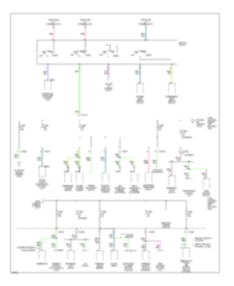
Power Distribution Wiring Diagram (4 of 5) for MINI Cooper S 2007
List of elements for Power Distribution Wiring Diagram (4 of 5) for MINI Cooper S 2007:
- (cooper s & bosch)
- (valeo & denso)
- A/t
- Abs w/ traction
- Abs w/o traction
- Abs/dsc unit (w dsc) abs control module (w/o dsc)
- Acc
- Control
- Control, w/ dsc
- Cooper s
- Cvt switch
- Data link connector
- Digital motor electronics control unit
- Driver outside mirror
- Driver's seat heating switch
- Electro- chromic rear view mirror
- Electronic immobilizer control unit
- From fuse f12 (diagram 4 of 5)
- From fuse fl7 (diagram 1 of 5)
- From k fuse f36 (diagram 4 of 5)
- Fuse f12 20a
- Fuse f13 5a (cooper s)
- Fuse f13 5a (cooper)
- Fuse f33 10a
- Fuse f34 10a
- Fuse f35 5a
- Fuse f36 5a
- Fuse f38 10a
- Fuse f40 5a
- Fuse f41 5a
- Fuse holder 2 (behind left footwell trim)
- Gear position switch
- Generator
- Headlight washer module
- Ignition switch
- Instrument cluster control module
- Left windshield washer jet heater
- M/t
- Mirror adjustment switch
- Nca
- Off
- Park distance control unit
- Passenger outside mirror
- Passenger's seat heating switch
- Red
- Reversing light switch
- Right windshield washer jet heater
- Run
- Start
- Steering angle sensor
- Steering control module fan relay
- Steering control unit/hydraulic pump
- Switch panel
- To fuse f39 (diagram 4 of 5)
- To fuse f6 (diagram 5 of 5)
- To ignition switch (diagram 4 of 5)
- Transmission control unit
- W/o mrs system 5
- Windshield defroster relay
- X10178
- X10204
- X10205
- X10206
- X10207
- X11177
- X1659
- X60004
- X6975
Power Distribution Wiring Diagram (5 of 5) for MINI Cooper S 2007
List of elements for Power Distribution Wiring Diagram (5 of 5) for MINI Cooper S 2007:
- Boost radio
- Brake light switch
- Clutch switch module
- Driver's seat belt hall sensor
- Eject box
- Electronic immobilizer control unit
- From fuse f29 (diagram 5 of 5)
- From fuse f31 (diagram 2 of 5)
- From ignition switch (diagram 4 of 5)
- From m fuse f29 (diagram 5 of 5)
- Front cigar lighter
- Front cigarette lighter relay
- Front washer pump relay
- Fuse f10 5a
- Fuse f11 5a
- Fuse f18 5a
- Fuse f29 15a
- Fuse f30 5a
- Fuse f32 15a
- Fuse f6 5a
- Fuse f7 5a
- Fuse f8 5a
- Fuse f9 5a
- Fuse holder 2 (behind left footwell trim)
- General module control unit
- Heating & a/c control module
- Indicator lamp, passenger deactivation
- Instrument cluster control module
- Interior lights system
- Interior temperature/ fan sensor
- Mrs system 5
- Multiple restraint system control unit
- Navigation computer
- Nca
- On-board monitor
- Passenger air bag deactivation switch
- Radio control module
- Rain sensor
- Rear washer pump relay
- Red
- Seat occupancy recognition
- To front cigarette lighter relay (diagram 5 of 5)
- To fuse f10 (diagram 5 of 5)
- Transmission control unit
- Turn indicator/ low beam switch
- Universal electronics charging & hands-free module
- W/ telephone provisions
- W/ universal electronics charging & hands-free module
- W/o mrs system 5
- Wave radio
- X10199
- X10200
- X10201
- X10203
- X10206
- X10207
- X1108 (left door)
- X11177
- X11633
- X1213
- X1313
- X151 (right side of right footwell)
- X1659
- X18126
- X2519
- X254
- X9320
POWER DOOR LOCKS
Power Door Locks Wiring Diagram, Convertible for MINI Cooper S 2007
List of elements for Power Door Locks Wiring Diagram, Convertible for MINI Cooper S 2007:
- (left door) x1108
- (left rear of trunk)
- (right side of engine compt)
- Central locking drive, trunk lid/tailgate (center rear of trunk)
- Computer data lines system
- Diode
- Driver's door lock
- Driver's door microwave sensor
- Fuel filler door lock
- Fuse f1 30a
- Fuse f14 10a
- Fuse f19 30a
- Fuse f23 20a
- Fuse f24 5a
- Fuse f4 5a
- Fuse f7 5a
- Fuse fl 12 50a
- Fuse fl 8 50a
- Fuse holder 2 (behind left footwell trim)
- Fuse holder 3 (left side of engine compt)
- General module control unit (behind right footwell)
- Hot at all times
- Hot in accy, run and start
- License plate lights
- Not used
- Passenger's door lock
- Passenger's door microwave sensor
- Rear left microwave sensor
- Rear right microwave sensor
- Red
- Siren w/ tilt alarm sensor
- Switch panel
- Theft ind
- Trunk lid contact switch
- Turn signal/ headlight dimmer switch
- Underhood light switch
- X10200
- X10201
- X10202
- X10206
- X10207
- X1108 (left door)
- X13230 (under left rear seat)
- X151 (right side of right footwell)
- X165
- X165 (right side of engine compt)
- X179 (below right rear seat)
- X253
- X254
- X255
- X332
- X4009
- X4010
- X490
- X490 (left rear of trunk)
- X494 (right rear side of luggage compt)
Power Door Locks Wiring Diagram, Except Convertible for MINI Cooper S 2007
List of elements for Power Door Locks Wiring Diagram, Except Convertible for MINI Cooper S 2007:
- (left door) x1108
- (left rear side of luggage compt)
- (not used)
- (right side of engine compt)
- Central locking drive, trunk lid/tailgate
- Central locking remote control (under front headliner)
- Computer data lines system
- Driver's door lock
- Fuel filler door lock
- Fuse f1 30a
- Fuse f14 10a
- Fuse f19 30a
- Fuse f23 20a
- Fuse f24 5a
- Fuse f4 5a
- Fuse f7 5a
- Fuse fl 12 50a
- Fuse fl 8 50a
- Fuse holder 2 (behind left footwell trim)
- Fuse holder 3 (left side of engine compt)
- General module control unit (behind right footwell)
- Hot at all times
- Hot in accy, run and start
- Interior protection 1 control module (in headliner)
- License plate lights
- Passenger's door lock
- Power distribution system
- Red
- Siren w/ tilt sensor
- Switch panel
- Theft ind
- Turn signal/ headlight dimmer switch
- Underhood light switch
- X10200
- X10201
- X10202
- X10206
- X10207
- X1108 (left door)
- X13230 (left door)
- X151 (right side of right footwell)
- X165
- X165 (right side of engine compt)
- X179 (right door)
- X253
- X254
- X255
- X332
- X4009
- X4010
- X490
- X494 (right rear side of luggage compt)
POWER MIRRORS
Electrochromic Mirror Wiring Diagram for MINI Cooper S 2007
List of elements for Electrochromic Mirror Wiring Diagram for MINI Cooper S 2007:
- (lower left of transmission)
- A/t
- Back-up light switch
- Cvt switch (except cooper s)
- Electrochromic rear view mirror
- Exterior lights, transmission, & navigation system
- Fuse f13 5a
- Fuse f35 5a
- Fuse holder 2 (behind left footwell trim)
- Gear position switch (cooper s)
- General module control unit (behind right footwell)
- Hot in on or start
- M/t
- X10204
- X10206
- X13230 (convertible: (under left rear seat) (coupe: left door)
- X254
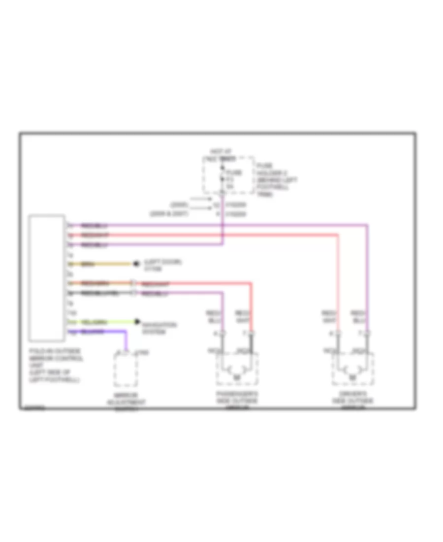
Fold-back Mirrors Wiring Diagram for MINI Cooper S 2007
List of elements for Fold-back Mirrors Wiring Diagram for MINI Cooper S 2007:
- (2005)
- (2006 & 2007)
- (left door) x1108
- Driver's side outside mirror
- Fold-in outside mirror control unit (left side of left footwell)
- Fuse f3 5a
- Fuse holder 2 (behind left footwell trim)
- Hot at all times
- Mirror adjustment switch
- Navigation system
- Nca
- Passenger's side outside mirror
- X10200
- X160
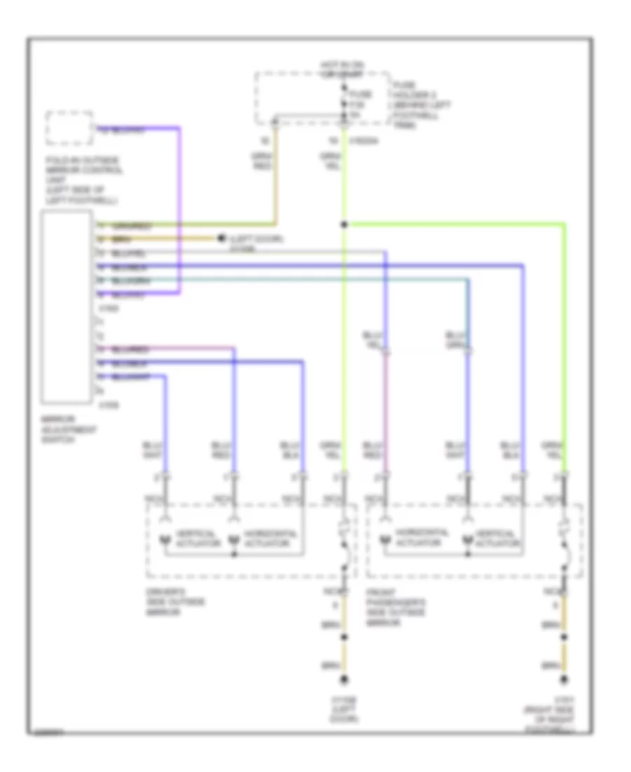
Power Mirror Wiring Diagram for MINI Cooper S 2007
List of elements for Power Mirror Wiring Diagram for MINI Cooper S 2007:
- (left door) x1108
- Driver's side outside mirror
- Fold-in outside mirror control unit (left side of left footwell)
- Front passenger's side outside mirror
- Fuse f35 5a
- Fuse holder 2 (behind left footwell trim)
- Horizontal actuator
- Hot in on or start
- Mirror adjustment switch
- Nca
- Vertical actuator
- Vertical m actuator
- X10204
- X1108 (left door)
- X151 (right side of right footwell)
- X159
- X160
POWER SEATS
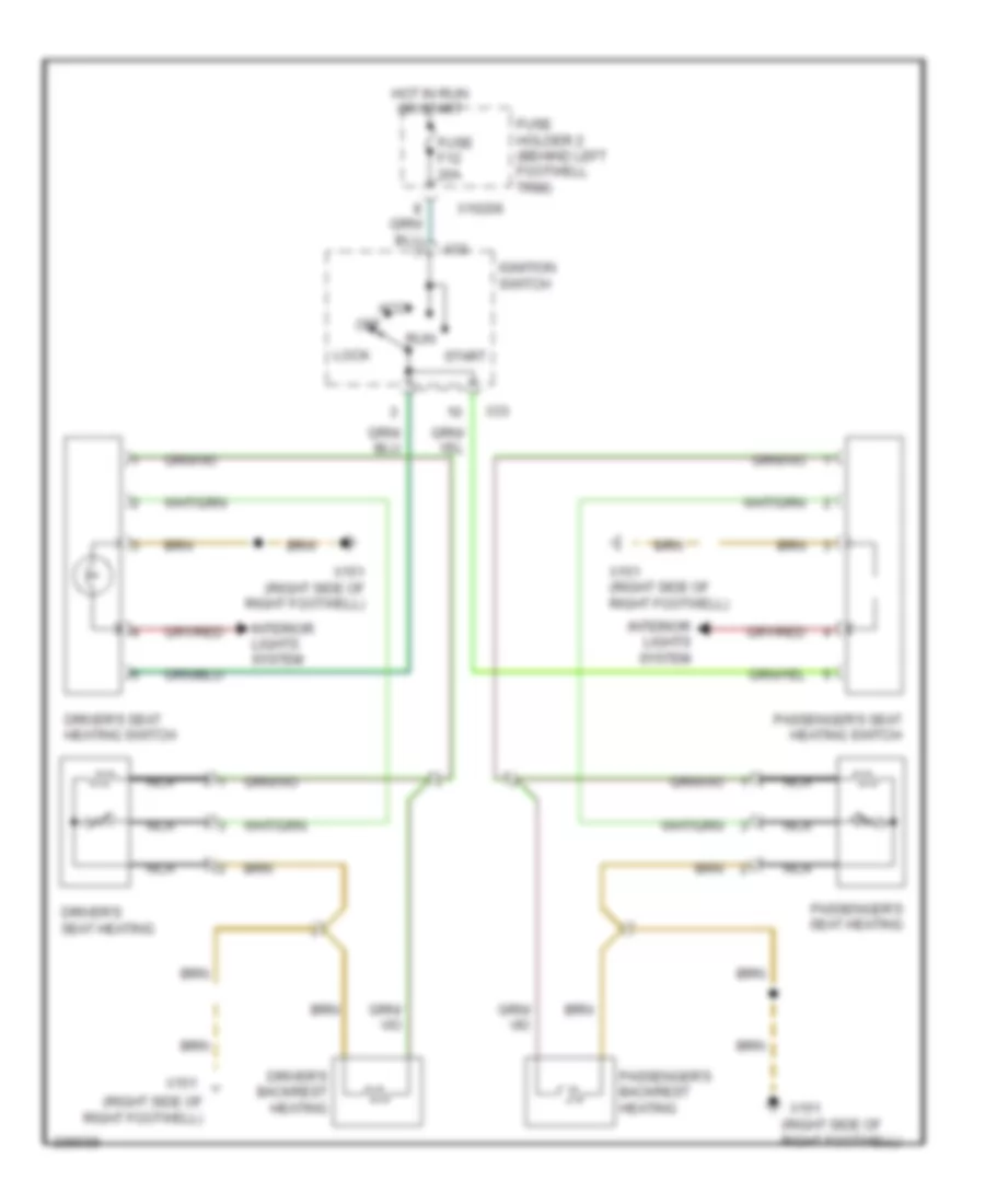
Heated Seats Wiring Diagram for MINI Cooper S 2007
List of elements for Heated Seats Wiring Diagram for MINI Cooper S 2007:
- (right side of right footwell)
- Acc
- Driver's backrest heating
- Driver's seat heating
- Driver's seat heating switch
- Fuse f12 20a
- Fuse holder 2 (behind left footwell trim)
- Hot in run or start
- Ignition switch
- Interior lights system
- Lock
- Nca
- Off
- Passenger's backrest heating
- Passenger's seat heating
- Passenger's seat heating switch
- Run
- Start
- X10206
- X151
- X151 (right side of right footwell)
- X33
POWER TOP/SUNROOF
Convertible Top Wiring Diagram for MINI Cooper S 2007
List of elements for Convertible Top Wiring Diagram for MINI Cooper S 2007:
- (under left rear seat) x13230
- (w/ storage compartment lock)
- Catch hall sensor
- Computer data lines system
- Convertible soft top control module (left rear passenger compt)
- Convertible top closed hall sensor
- Convertible top control button
- Convertible top folded down hall sensor
- Convertible top motor
- Convertible top relay 1
- Convertible top relay 2
- Cross brace microswitch (rear parcel shelf)
- Digital motor electronic control unit (left side of engine compt)
- Fuse f01 5a
- Fuse f15 20a
- Fuse fl3 40a
- Fuse holder 2 (behind left footwell trim)
- Fuse holder 3 (left side of engine compt)
- Hot at all times
- Interior lights system
- Left storage compt lock microswitch
- Left storage compt lock motor
- Nca
- Rear window shelf microswitch (rear parcel shelf)
- Red
- Right storage compt lock motor
- Right storage compt lock microswitch
- Sliding canvas sunroof motor
- Sliding canvas sunroof closed hall sensor
- Sliding canvas sunroof open hall sensor
- Sliding canvas sunroof relay 1
- Sliding canvas sunroof relay 2
- X10206
- X1108 (left door)
- X13037
- X13038
- X13230 (under left rear seat)
- X167 (left side of engine compt)
- X4007
- X4013
- X490 (left rear of trunk)
- X494 (right rear side of luggage compt)
- X60004
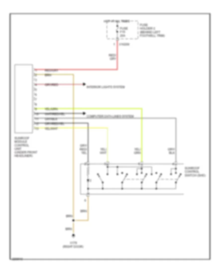
Sunroof Wiring Diagram for MINI Cooper S 2007
List of elements for Sunroof Wiring Diagram for MINI Cooper S 2007:
- Computer data lines system
- Fuse f15 20a
- Fuse holder 2 (behind left footwell trim)
- Hot at all times
- Interior lights system
- Sunroof control switch (shd)
- Sunroof module control unit (under front headliner)
- X10206
- X179 (right door)
POWER WINDOWS
Power Windows Wiring Diagram, Convertible for MINI Cooper S 2007
List of elements for Power Windows Wiring Diagram, Convertible for MINI Cooper S 2007:
- Central lock
- Driver's door lock system
- Driver's window motor
- Fuse f1 30a
- Fuse f19 30a
- Fuse holder 2 (behind left footwell trim)
- General module control unit (behind right footwell)
- Hot at all times
- Interior lights system
- Left window
- Passenger's door lock system
- Passenger's window motor
- Rear left window regulator motor
- Rear power window switch
- Rear right window regulator motor
- Right window
- Switch panel
- X10201
- X10202
- X1108 (left door)
- X13230 (under left rear seat)
- X151 (right side of right footwell)
- X253
- X255
- X332
Power Windows Wiring Diagram, Except Convertible for MINI Cooper S 2007
List of elements for Power Windows Wiring Diagram, Except Convertible for MINI Cooper S 2007:
- (left door) x13230
- (right side of right footwell)
- Central lock
- Driver's door lock system
- Driver's window motor
- Fuse f1 30a
- Fuse f19 30a
- Fuse holder 2 (behind left footwell trim)
- General module control unit (behind right footwell)
- Hot at all times
- Left window
- Passenger's door lock system
- Passenger's window motor
- Right window
- Switch panel
- X10201
- X10202
- X1108 (left door)
- X151
- X151 (right side of right footwell)
- X253
- X255
- X332
RADIO
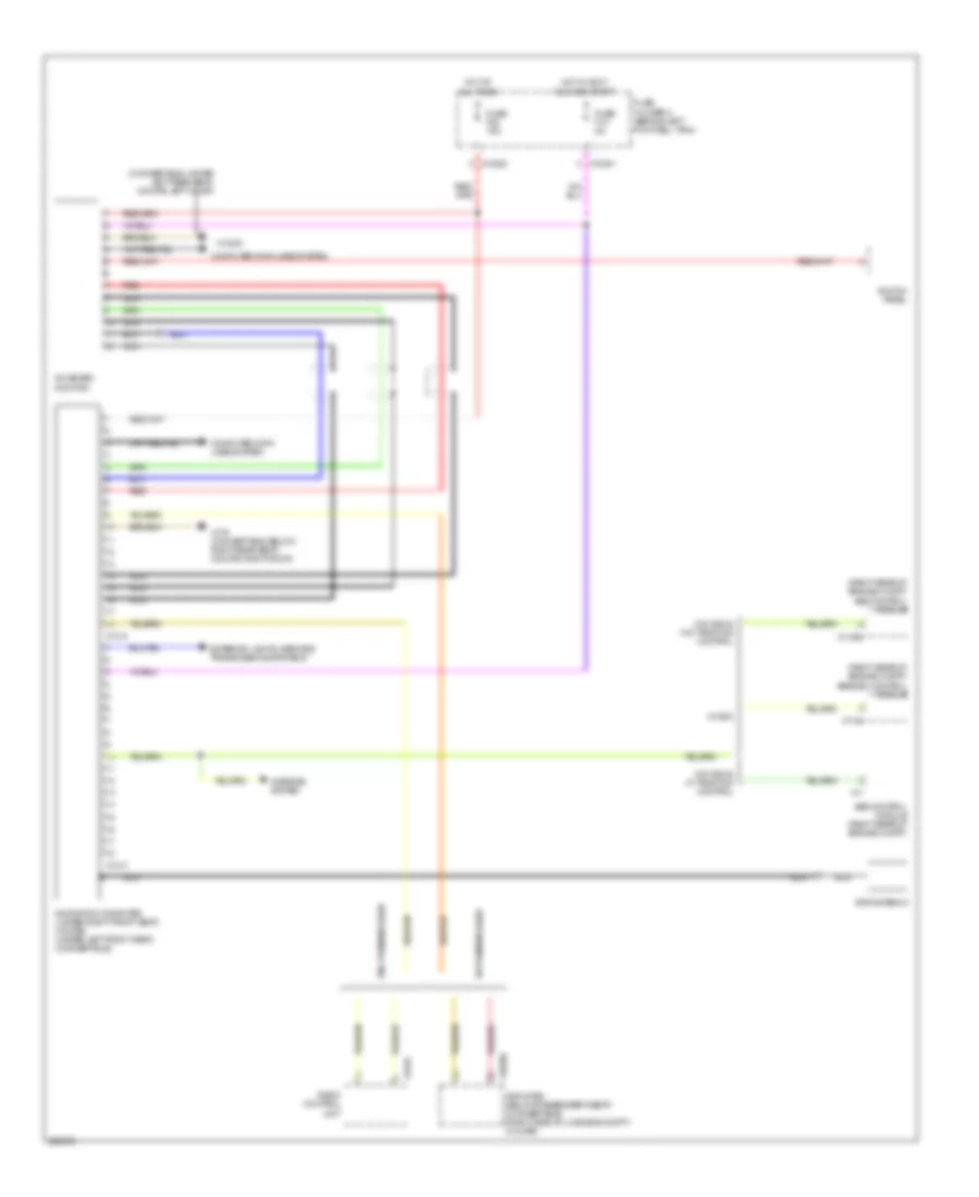
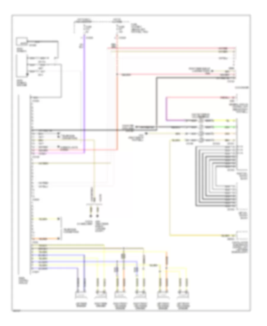
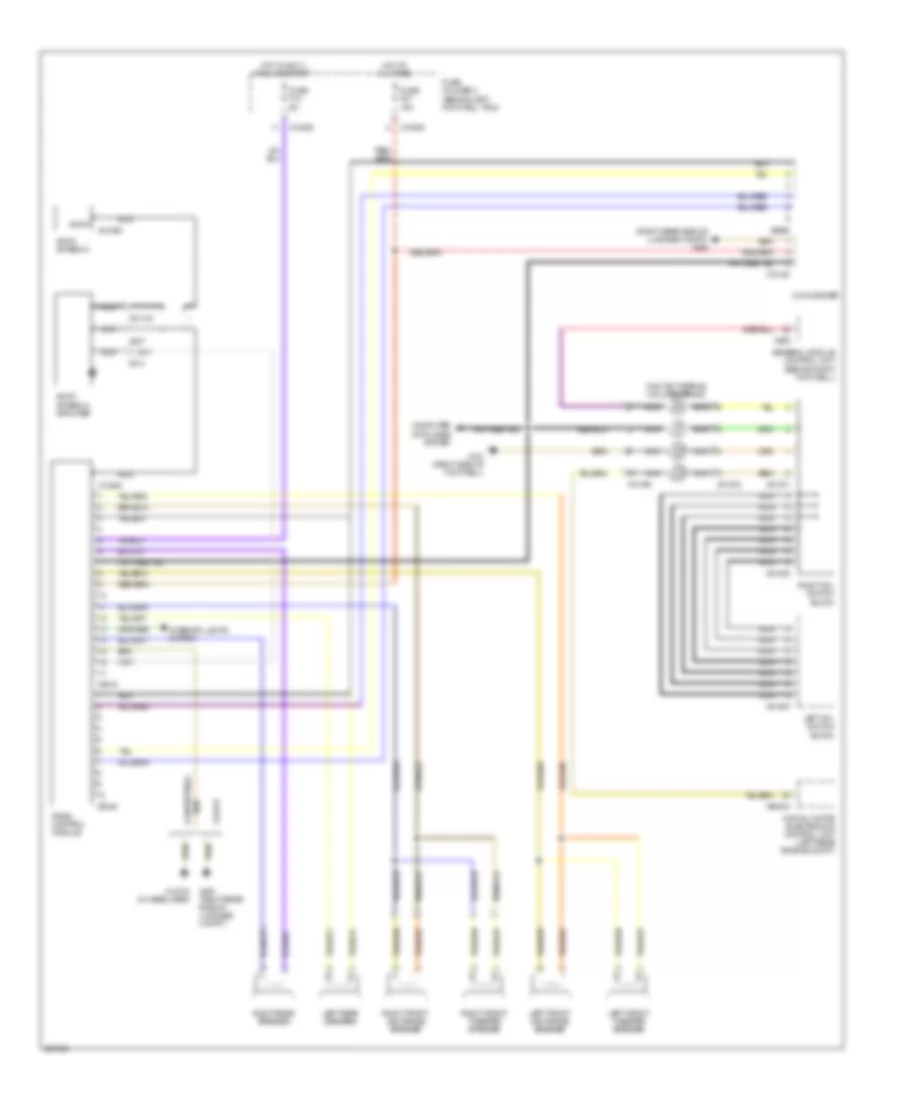
Base Radio Wiring Diagram, with Telephone Provisions for MINI Cooper S 2007
List of elements for Base Radio Wiring Diagram, with Telephone Provisions for MINI Cooper S 2007:
- (right rear side of luggage compt) x494
- Am/fm
- Am/fm antenna
- Am/fm antenna amplifier
- Cd changer
- Computer data lines system
- Contact spring (volute spring)
- Convertible
- Coupe
- Digital motor electronics control unit (left rear engine compt)
- Fuse f10 5a
- Fuse f27 15a
- Fuse holder 2 (behind left footwell trim)
- General module control unit (behind right footwell)
- Hot at all times
- Hot in accy, run and start
- Interior lights system
- Left front high-range speaker
- Left front mid-range speaker
- Left mfl switch block
- Left rear speaker
- Nca
- Radio control module
- Right front high-range speaker
- Right front mid-range speaker
- Right mfl switch block
- Right rear speaker
- Telephone connections
- X01000
- X01001
- X01002
- X01003
- X01068
- X01104
- X10195
- X10205
- X10206
- X13016 (in headliner)
- X13364
- X13647
- X151 (right side of footwell)
- X1532
- X18126
- X18180
- X18805
- X255
- X494 (right rear side of luggage compt.)
- X60004
- X807
- X813
- X9960
Base Radio Wiring Diagram, without Telephone Provisions for MINI Cooper S 2007
List of elements for Base Radio Wiring Diagram, without Telephone Provisions for MINI Cooper S 2007:
- (right rear side of luggage compt) x494
- Am/fm
- Am/fm antenna
- Am/fm antenna amplifier
- Cd changer
- Computer data lines system
- Contact spring (volute spring)
- Convertible
- Coupe
- Digital motor electronics control unit (left rear engine compt)
- Fuse f10 5a
- Fuse f27 15a
- Fuse holder 2 (behind left footwell trim)
- General module control unit (behind right footwell)
- Hot at all times
- Hot in accy, run and start
- Interior lights system
- Left front mid-range speaker
- Left front tweeter speaker
- Left mfl switch block
- Left rear speaker
- Nca
- Radio control module
- Right front mid-range speaker
- Right front tweeter speaker
- Right mfl switch block
- Right rear speaker
- X01000
- X01001
- X01002
- X01003
- X01068
- X01104
- X10195
- X10205
- X10206
- X13016 (in headliner)
- X13364
- X151 (right side of footwell)
- X18180
- X2519
- X255
- X494 (right rear side of luggage compt.)
- X60004
- X807
- X813
- X9345
- X9960
Premium Sound Radio Wiring Diagram (1 of 2) for MINI Cooper S 2007
List of elements for Premium Sound Radio Wiring Diagram (1 of 2) for MINI Cooper S 2007:
- (convertible)
- (coupe)
- Am/fm
- Amplifier
- Amplifier (convertible: below passenger's seat) (coupe: right side of luggage compt)
- Antenna
- Fuse f10 5a
- Fuse f27 15a
- Fuse holder 2 (behind left footwell trim)
- Hot at all times
- Hot in accy, run and start
- Interior lights system
- Nca
- Radio control module
- Telephone connections
- X01068
- X01104
- X10205
- X10206
- X10266
- X13016 (in headliner)
- X13364
- X13647
- X1532
- X18126
- X18805
- X494 (right rear of luggage compt.)
- X494 (right rear side of luggage compt)
- X807
- X813
Premium Sound Radio Wiring Diagram (2 of 2) for MINI Cooper S 2007
List of elements for Premium Sound Radio Wiring Diagram (2 of 2) for MINI Cooper S 2007:
- (right rear side of luggage compt) x494
- (under left front seat) navigation computer
- Cd changer
- Computer data lines system
- Contact spring (volute spring)
- Digital motor electronics control unit (left rear of engine compt)
- General module control unit (behind right footwell)
- Left front mid-range speaker
- Left front tweeter speaker
- Left mfl switch block
- Left rear speaker
- Nca
- Right front mid-range speaker
- Right front tweeter speaker
- Right mfl switch block
- Right rear speaker
- W/ hifi
- W/o hifi
- X01000
- X01001
- X01002
- X01003
- X10195
- X1261
- X1312
- X151 (right side of right footwell)
- X18180
- X18514
- X18515
- X255
- X397
- X60004
- X9960
SHIFT INTERLOCK
Shift Interlock Wiring Diagram for MINI Cooper S 2007
List of elements for Shift Interlock Wiring Diagram for MINI Cooper S 2007:
- (convertible: under left rear seat) (coupe: left door) x13230
- Brake light switch
- Digital motor electronics control unit (left side of engine compt)
- Dme main relay
- Fuse f01 5a
- Fuse f04 15a
- Fuse f26 10a
- Fuse f6 5a
- Fuse holder 2 (behind left footwell trim)
- Gearshift lock
- Hot at all times
- Hot in accy, run and start
- Nca
- Shift lock relay
- X10200
- X10205
- X10207
- X151 (right side of right footwell)
- X167 (left side of engine compt)
- X4009
- X4013
- X60004
STARTING/CHARGING
Charging Wiring Diagram for MINI Cooper S 2007
List of elements for Charging Wiring Diagram for MINI Cooper S 2007:
- Battery
- Bosch
- Cooper s
- Denso
- Denso & cooper s
- Digital motor electronics control unit (left side of engine compt)
- Fuse f38 10a
- Fuse holder 2 (behind left footwell trim)
- Generator
- Hot in on or start
- Instrument cluster
- Red
- Starter
- Steering control module
- Valeo
- X10207
- X11177
- X6000
- X6402
Starting Wiring Diagram for MINI Cooper S 2007
List of elements for Starting Wiring Diagram for MINI Cooper S 2007:
- Acc
- Battery
- Electronic immobilizer control unit (left side of dash)
- Fuse fl7 50a
- Fuse holder 3 (left side of engine compt)
- Generator
- Hot at all times
- Ignition switch
- Lock
- Off
- Red
- Run
- Start
- Starter
- X4010
- X6402
SUPPLEMENTAL RESTRAINTS
Supplemental Restraints Wiring Diagram (1 of 2) for MINI Cooper S 2007
List of elements for Supplemental Restraints Wiring Diagram (1 of 2) for MINI Cooper S 2007:
- (under center console)
- Deactivate ind
- Driver's seat belt tensioner
- Driver's side airbag inflator
- Drvr seat belt
- Drvr seat belt +
- Drvr seat belt -
- Drvr side +
- Drvr side -
- Ground
- K-bus sig
- L b-pillar sens +
- L b-pillar sens -
- Left "b" pillar airbag sensor
- Left front airbag sensor
- Left head +
- Left head -
- Left head airbag inflator
- Lf door sens +
- Lf door sens -
- Lf sens +
- Lf sens -
- Multiple restraint system control unit (center tunnel under carpet)
- Nca
- Pass seat belt
- Pass seat belt +
- Pass seat belt -
- Pass side +
- Pass side -
- Passenger's seat belt tensioner
- Passenger's side airbag inflator
- R b-pillar sens +
- R b-pillar sens -
- Rf door sens +
- Rf door sens -
- Rf sens +
- Rf sens -
- Right "b" pillar airbag sensor
- Right front airbag sensor
- Right head +
- Right head -
- Right head airbag inflator
- Safety battery +
- Safety battery -
- Safety battery terminal
- Shield
- Term 15
- X10214
- X10215
- X10216
- X10395
- X10400
- X10429
- X1770
- X18069
- X46
Supplemental Restraints Wiring Diagram (2 of 2) for MINI Cooper S 2007
List of elements for Supplemental Restraints Wiring Diagram (2 of 2) for MINI Cooper S 2007:
- (under center console) x46
- Computer data lines system
- Driver's airbag inflator assemblies
- Driver's seat belt buckle contact
- Drvr airbag +
- Drvr airbag -
- Fuse f18 5a
- Fuse holder 2 (behind left footwell trim)
- Hot in accy, run and start
- Instrument cluster control module
- K-bus sig
- Left front door airbag sensor
- Multiple restraint system control unit (center tunnel under carpet)
- Nca
- Pass airbag +
- Pass airbag -
- Passenger airbag deactivation indicator lamp
- Passenger's airbag inflator assemblies
- Passenger's seat belt buckle contact
- Right front door airbag sensor
- Seat occupancy recognition
- Volute spring
- X01099
- X10179
- X10203
- X11175
- X46 (under center console)
- X548
- X783
TRANSMISSION
1.6L
1.6L, Transmission Wiring Diagram for MINI Cooper S 2007
List of elements for 1.6L, Transmission Wiring Diagram for MINI Cooper S 2007:
- (in left door) x1108
- (left side of dash) electronic immobilizer control unit
- Automatic transmission (cvt) switch
- Central shift unit
- Computer data lines system
- Contact spring (volute spring)
- Digital motor electronics control unit (left side of engine compt)
- Exterior lights system
- Fuse f04 15a
- Fuse f13 5a
- Fuse holder 2 (behind left footwell trim)
- Fuse holder 3 (left side of engine compt)
- Gear indicator light
- Hot in on or start
- Hot w/ dme main relay energized
- Interior lights system
- Left button pad
- Nca
- Steering wheel button
- Transmission control unit (left side of left footwell)
- Transmission valve unit
- X01003
- X10195
- X10206
- X1108 (in left door)
- X151 (right side of right footwell)
- X19561
- X4009
- X6000
- X8687
1.6L TURBO
1.6L Turbo, Transmission Wiring Diagram (1 of 2) for MINI Cooper S 2007
List of elements for 1.6L Turbo, Transmission Wiring Diagram (1 of 2) for MINI Cooper S 2007:
- Computer data lines system
- Electronic immobilizer control unit (left side of dash)
- Fuse f04 15a
- Fuse f13 5a
- Fuse f29 15a
- Fuse holder 2 (behind left footwell trim)
- Fuse holder 3 (left side of engine compt)
- Hot at all times
- Hot in on or start
- Hot w/ dme main relay energized
- Navigation, mirrors, exterior lights system
- Red
- Transmission control unit (left side of left footwell)
- Transmission range position switch
- X10206
- X1108 (in left door)
- X11630
- X11631
- X11632
- X11633
- X11634
- X1659
- X175 (left side of engine compt)
- X4009
1.6L Turbo, Transmission Wiring Diagram (2 of 2) for MINI Cooper S 2007
List of elements for 1.6L Turbo, Transmission Wiring Diagram (2 of 2) for MINI Cooper S 2007:
- Central shift unit
- Contact spring (volute spring)
- Gear indicator light
- Interior lights system
- Left button pad
- Nca
- Shift lock selector lever lock
- Steering wheel button
- X01003
- X10195
- X1108 (in left door)
- X151 (right side of right footwell)
TRUNK, TAILGATE, FUEL DOOR
Trunk, Tailgate, Fuel Door Wiring Diagram, Convertible for MINI Cooper S 2007
List of elements for Trunk, Tailgate, Fuel Door Wiring Diagram, Convertible for MINI Cooper S 2007:
- (left rear of trunk) x490
- Central locking drive, trunk lid (center rear of trunk)
- Diode
- Fuel filler door lock
- Fuse f23 20a
- Fuse holder 2 (behind left footwell trim)
- General module control unit (behind right footwell)
- Hot at all times
- License plate lights
- Tailgate open
- Trunk lid contact switch
- X10207
- X179 (below right rear seat)
- X253
- X254
- X332
- X490 (left rear of trunk)
Trunk, Tailgate, Fuel Door Wiring Diagram, Except Convertible for MINI Cooper S 2007
List of elements for Trunk, Tailgate, Fuel Door Wiring Diagram, Except Convertible for MINI Cooper S 2007:
- (left rear side of luggage compt) x490
- Fuel filler door lock
- Fuse f23 20a
- Fuse holder 2 (behind left footwell trim)
- General module control unit (behind right footwell)
- Hot at all times
- License plate lights
- Tailgate open
- Trunk lid switch
- X10207
- X179 (right door)
- X253
- X254
- X332
- X494 (right rear side of luggage compt)
WARNING SYSTEMS
Tire Pressure Monitoring Wiring Diagram for MINI Cooper S 2007
List of elements for Tire Pressure Monitoring Wiring Diagram for MINI Cooper S 2007:
- (under left rear seat)
- Can
- Computer data lines system
- Fuse f3 5a
- Fuseholder 2 (behind left footwell trim)
- Ground
- Hot at all times
- Left front electronic wheel module/ transmitter
- Left rear electronic wheel module/ transmitter
- Lf transmit
- Lr transmit
- Rdc antenna
- Rf transmit
- Right front electronic wheel module/ transmitter
- Right rear electronic wheel module/ transmitter
- Rr transmit
- Switch
- Tire pressure control module
- Tire pressure control switch
- X10200
- X1108 (in left door)
- X13230
- X18034
WIPER/WASHER
Front Wiper/Washer Wiring Diagram, Convertible for MINI Cooper S 2007
List of elements for Front Wiper/Washer Wiring Diagram, Convertible for MINI Cooper S 2007:
- (left side of engine compt)
- Computer data lines system
- Fast/ slow wiper motor relay
- Front washer pump relay
- Fuse f09 20a
- Fuse f11 5a
- Fuse f23 20a
- Fuse f7 5a
- Fuse holder 2 (behind left footwell trim)
- Fuse holder 3 (left side of engine compt)
- General module control unit (behind right footwell)
- Hot at all times
- Hot in accy,
- Hot in on or start
- Rain sensor (windshield top)
- Run and start
- Washer fluid level switch
- Washer pump
- Wiper motor
- Wiper motor relay
- Wiper/washer switch
- X10200
- X10207
- X1108 (left door)
- X13230 (under left rear seat)
- X165 (right side of engine compt)
- X175
- X253
- X254
- X255
- X332
- X4009
- X4010
- X4013
Front Wiper/Washer Wiring Diagram, Except Convertible for MINI Cooper S 2007
List of elements for Front Wiper/Washer Wiring Diagram, Except Convertible for MINI Cooper S 2007:
- (left side of engine compt)
- Computer data lines system
- Fast/ slow wiper motor relay
- Front washer pump relay
- Fuse f09 20a
- Fuse f11 5a
- Fuse f23 20a
- Fuse f7 5a
- Fuse holder 2 (behind left footwell trim)
- Fuse holder 3 (left side of engine compt)
- General module control unit (behind right footwell)
- Hot at all times
- Hot in acc,
- Hot in on or start
- Rain sensor (windshield top)
- Rear washer pump relay
- Run and start
- Washer fluid level switch
- Washer pump
- Wiper motor
- Wiper motor relay
- Wiper/washer switch
- X10200
- X10207
- X1108 (left door)
- X13230 (left door)
- X165 (right side of engine compt)
- X175
- X253
- X254
- X255
- X332
- X4009
- X4010
- X4013
Headlamp Washer Wiring Diagram for MINI Cooper S 2007
List of elements for Headlamp Washer Wiring Diagram for MINI Cooper S 2007:
- Fuse f14 10a
- Fuse f19 30a
- Fuse f25 30a
- Fuse holder 2 (behind left footwell trim)
- General module control unit (behind right footwell)
- Headlight washer module
- Headlight washer pump
- Hot at all times
- Wash
- Wiper/washer switch
- X10202
- X10205
- X10206
- X13230 (convertible: under left rear seat) (coupe: left door)
- X151 (right side of right footwell)
- X175 (left side of engine compt)
- X254
- X255
- X332
Rear Wiper/Washer Wiring Diagram for MINI Cooper S 2007
List of elements for Rear Wiper/Washer Wiring Diagram for MINI Cooper S 2007:
- (left door)
- Front washer pump relay
- Fuse f11 5a
- Fuse f17 15a
- Fuse f23 20a
- Fuse holder 2 (behind left footwell trim)
- General module control unit (behind right footwell)
- Hot at all times
- Hot in on or start
- Rear washer pump relay
- Rear window wiper motor (on liftgate)
- Rear wiper motor relay
- Washer fluid level switch
- Window washer pump
- Wiper/washer switch
- X10204
- X10207
- X1108
- X1108 (left door)
- X13230 (left door)
- X165 (right side of engine compt)
- X253
- X254
- X255
- X332
Washer Jet Heater Wiring Diagram for MINI Cooper S 2007
List of elements for Washer Jet Heater Wiring Diagram for MINI Cooper S 2007:
- (convertible: under left rear seat) (coupe: left door) x13230
- (left side of left footwell) clutch switch
- Accelerator pedal position sensor (right side of left footwell)
- Air conditioning system
- Anti-theft system
- Brake light switch (left side of left footwell)
- Catalyst oxygen sensor (front exhaust pipe)
- Computer data lines system
- Contact spring (volute spring)
- Cruise control system
- Digital motor electronics control unit (left side of engine compt)
- Exterior lights system
- Fuse f01 5a
- Fuse f6 5a
- Fuse holder 2 (behind left footwell trim)
- Fuse holder 3 (left side of engine compt)
- Hot at all times
- Hot in acc, run or start
- Nca
- Power tops system
- Shift interlock system
- X10200
- X13230 (under left rear seat) (convt) (left door) (coupe)
- X167 (left side of engine compt)
- X4013
- X6000
- X6004
- X6454