Diagram sections — 24 (39 total)
AIR CONDITIONING ANTI-LOCK BRAKES COMPUTER DATA LINES COOLING FAN CRUISE CONTROL DEFOGGERS ENGINE PERFORMANCE EXTERIOR LIGHTS GROUND DISTRIBUTION HEADLIGHTS HORN INSTRUMENT CLUSTER INTERIOR LIGHTS PASSIVE RESTRAINTS POWER DISTRIBUTION POWER DOOR LOCKS POWER MIRRORS POWER TOP/SUNROOF RADIO STARTING/CHARGING SUPPLEMENTAL RESTRAINTS TRANSMISSION WARNING SYSTEMS WIPER/WASHER
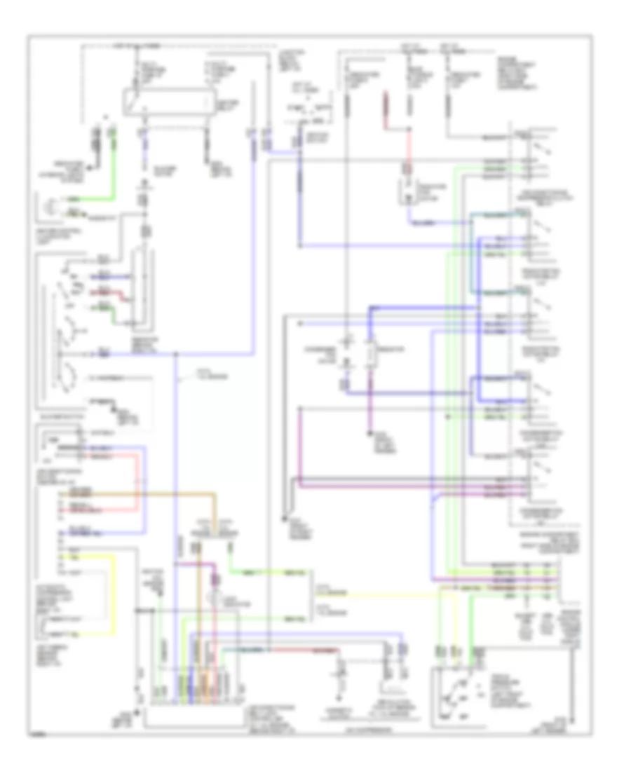
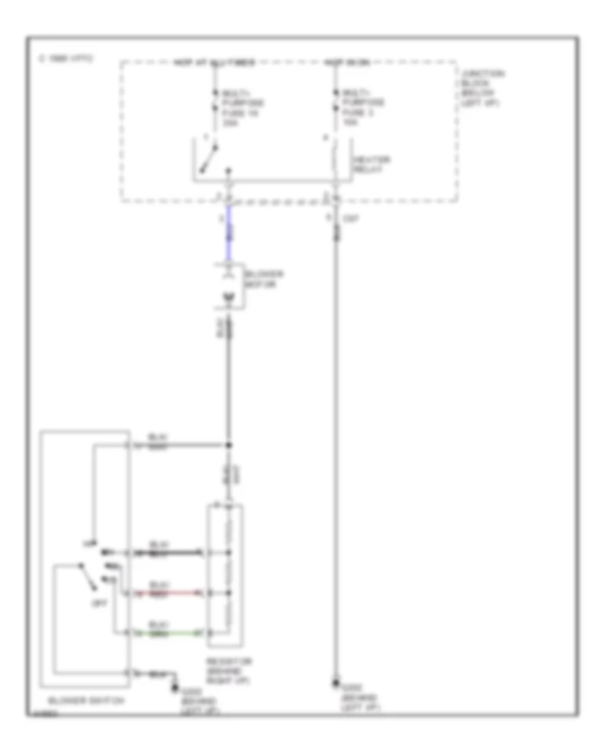
AIR CONDITIONING Air Conditioning Wiring Diagrams for Mitsubishi Expo 1994 List of elements for Air Conditioning Wiring Diagrams for Mitsubishi Expo 1994: 60 (on compressor) (w/ 1.8l engine) 2.4l calif fwd A/c A03x A04x A05x A07x A08x Acc on Air conditioning belt lock controller (w/ 1.8l engine) (behind right i/p) Air conditioning compressor clutch relay Air conditioning switch (center of i/p) Air thermo sensor (behind right i/p) Automatic compressor control unit (behind right i/p) Blower motor Blower switch C59 C61 C67 Condenser fan motor Condenser fan motor relay (hi) Condenser fan motor relay (lo) Control module (under right side of i/p) Dedicated fuse 3 (interior lights system) Dedicated fuse 6 25a Dedicated fuse 7 10a Econo Engine Engine compartment relay box (right side of engine compartment) Engine compartment relay box (right side of engine compartment) Except 2.4l calif fwd G100 (front of left fender) G101 (front of right fender) G202 (behind left i/p) Heater control illumination light Heater relay Hot at all times Ignition coil (engine rpm) Ignition switch Junction block (below left i/p) Lock Lock indicator Magnetic clutch Multi- purpose fuse 16 30a Multi- purpose fuse 3 10a Nca Off Radiator fan motor Radiator fan motor relay (hi) Radiator fan motor relay (lo) Resistor Resistor (behind right i/p) Revolution pick-up sensor Rheostat Start Sub fusible link 5 30a Triple pressure switch (left front of engine compartment) With 1.8l engine With 2.4l engine Heater Wiring Diagram for Mitsubishi Expo 1994 List of elements for Heater Wiring Diagram for Mitsubishi Expo 1994: 13 Blower motor Blower switch C 1995 vftc C67 G202 (behind left i/p) Heater relay Hot at all times Hot in on Junction block (below left i/p) Multi- purpose fuse 16 30a Multi- purpose fuse 3 10a Off Resistor (behind right i/p)
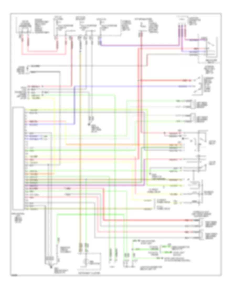
ANTI-LOCK BRAKES Anti-lock Brake Wiring Diagrams for Mitsubishi Expo 1994 List of elements for Anti-lock Brake Wiring Diagrams for Mitsubishi Expo 1994: 57 (under left side of i/p) 60a A09x A26 A27 Abs control unit (below center of i/p) Abs indicator Abs power relay C05 C29x C57 C58 C61 C64 C66 C67 D01 D03 Data link connector Diode (behind center of i/p) Engine compartment relay box (right side of engine compartment) G sensor (below center of i/p) (w/ all wheel drive) G100 (front of left fender) G201 (behind right side of i/p) G202 (behind left side of i/p) High mounted stop light Hot at all times Hot in on Hot in on or start Hydraulic unit (left front engine compartment) Instrument cluster Interior junction block (below left i/p) Interior relay box (below left i/p) Iod or storage connector Junction connector (below left i/p) Left front abs speed sensor Left rear abs speed sensor Main fusible link (abs) (positve battery terminal) Motor relay Multi-purpose fuse 11 10a Multi-purpose fuse 19 10a Multi-purpose fuse 3 10a Nca Open connector (below i/p) Red Resistor (above glovebox) Right front abs speed sensor Right rear abs speed sensor Solenoid valves Stop light Stop light switch (w/ auto-cruise control) Switch Valve relay W/ all wheel drive W/ auto- cruise W/ front wheel drive W/o auto- cruise
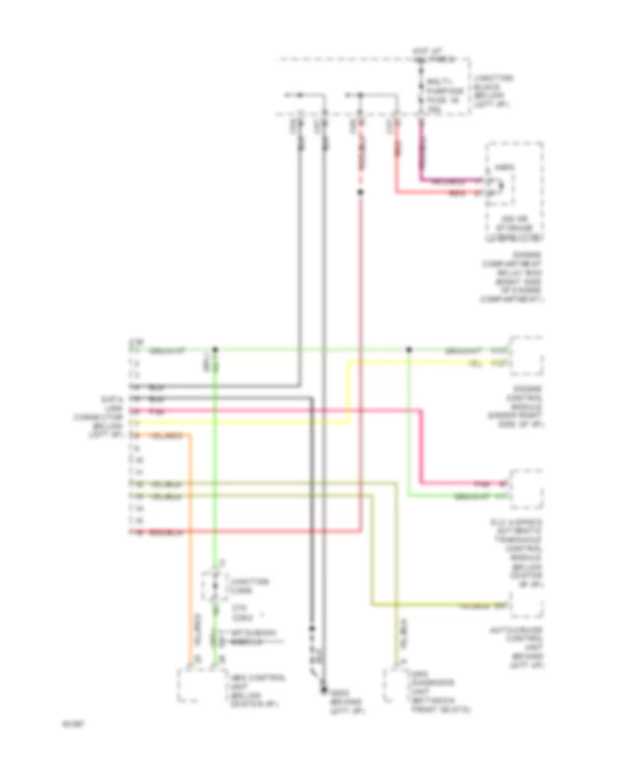
COMPUTER DATA LINES Computer Data Lines for Mitsubishi Expo 1994 List of elements for Computer Data Lines for Mitsubishi Expo 1994: 24 * mitsubishi models A09x Abs control unit (below center i/p) Auto-cruise control unit (behind left i/p) C38 C57 C64 C66 C67 C70 c28-2 Data link connector (below left i/p) Elc 4-speed automatic transaxle control module (below center of i/p) Engine compartment relay box (right side of engine compartment) Engine control module (under right side of i/p) G202 (behind left i/p) Hot at all times Iod or storage connector Junction block (below left i/p) Junction conn Multi- Pnk Purpose fuse 19 10a Red Srs diagnosis unit (between front seats)
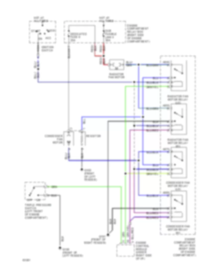
COOLING FAN Cooling Fan Wiring Diagram for Mitsubishi Expo 1994 List of elements for Cooling Fan Wiring Diagram for Mitsubishi Expo 1994: 26 A04x A05x A07x A08x Acc on Condenser fan motor Condenser fan motor relay (hi) Condenser fan motor relay (lo) Dedicated fuse 6 25a Engine compartment relay box (right side of engine compartment) Engine compartment relay box (right side of engine compartment) Engine control module (under right side of i/p) G100 (front of left fender) G101 (front of right fender) Hot at all times Ignition switch Lock Nca Off Radiator fan motor Radiator fan motor relay (hi) Radiator fan motor relay (lo) Resistor Start Sub fusible link 5 30a Triple pressure switch (left front of engine compartment)
CRUISE CONTROL Cruise Control Wiring Diagram for Mitsubishi Expo 1994 List of elements for Cruise Control Wiring Diagram for Mitsubishi Expo 1994: 68 (under center of i/p) * with 4spd a/t ** c71 ** mitsubishi only ** mitsubishi only Auto-cruise control actuator (right rear of engine compartment) Auto-cruise control main switch (right side of instrument cluster) Auto-cruise control switch Auto-cruise control unit (behind left i/p) C24 C25 C35 C57 C58 C61 C62 C63 C64 C66 C67 C70 c28-2 C77 Cancel Clock spring Clutch pedal position switch (auto-cruise) (below left i/p) c35 Control valve Cruise Ctp switch D01 D02 Data link connector (below left i/p) Elc 4-speed automatic transaxle control module Engine compartment relay box (right side of engine compartment) Engine control module (under right of i/p) G202 (behind left i/p) Hot at all times Hot in on Hot in on or acc Hot in on or start Ignition switch pin 5 (starting/ charging system) Ind Instrument cluster Iod or storage connector a09x Junction block (below left i/p) Junction connector (above right kick panel) Junction connector (below left i/p) Multi- purpose fuse 11 10a Multi- purpose fuse 17 15a Multi- purpose fuse 19 10a Multi- purpose fuse 4 10a Multi- purpose fuse 7 10a Nca Not used Od off Off Over drive switch (on gear selector) Red Reed Release valve Resume Rheostat Set Speedo- meter Stop light Stop light switch (behind left i/p) Throttle position sensor (center rear of engine compartment) W/ a/t W/ m/t
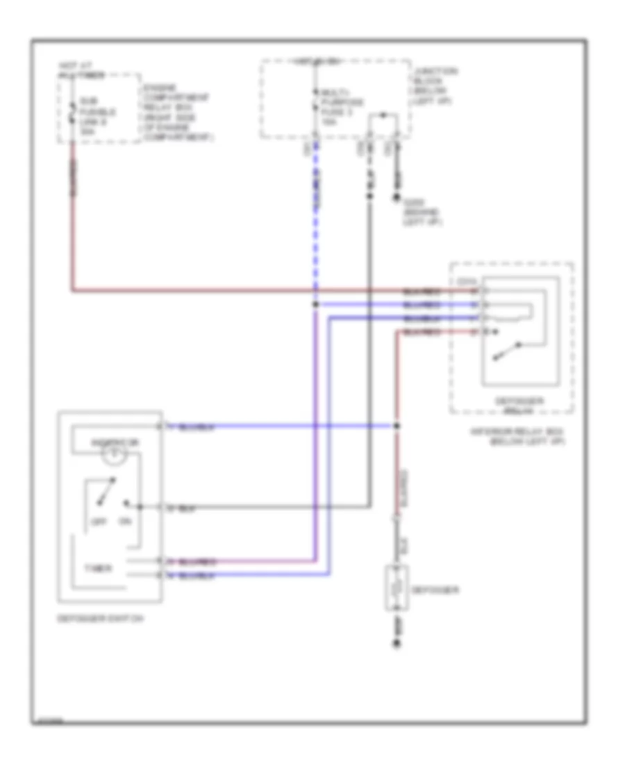
DEFOGGERS Defogger Wiring Diagram for Mitsubishi Expo 1994 List of elements for Defogger Wiring Diagram for Mitsubishi Expo 1994: 18 C31x C58 C61 C62 Defogger Defogger relay Defogger switch Engine compartment relay box (right side of engine compartment) G202 (behind left i/p) Hot at all times Hot in on Indicator Interior relay box (below left i/p) Junction block (below left i/p) Multi- purpose fuse 3 10a Off Sub fusible link 8 30a Timer
ENGINE PERFORMANCE
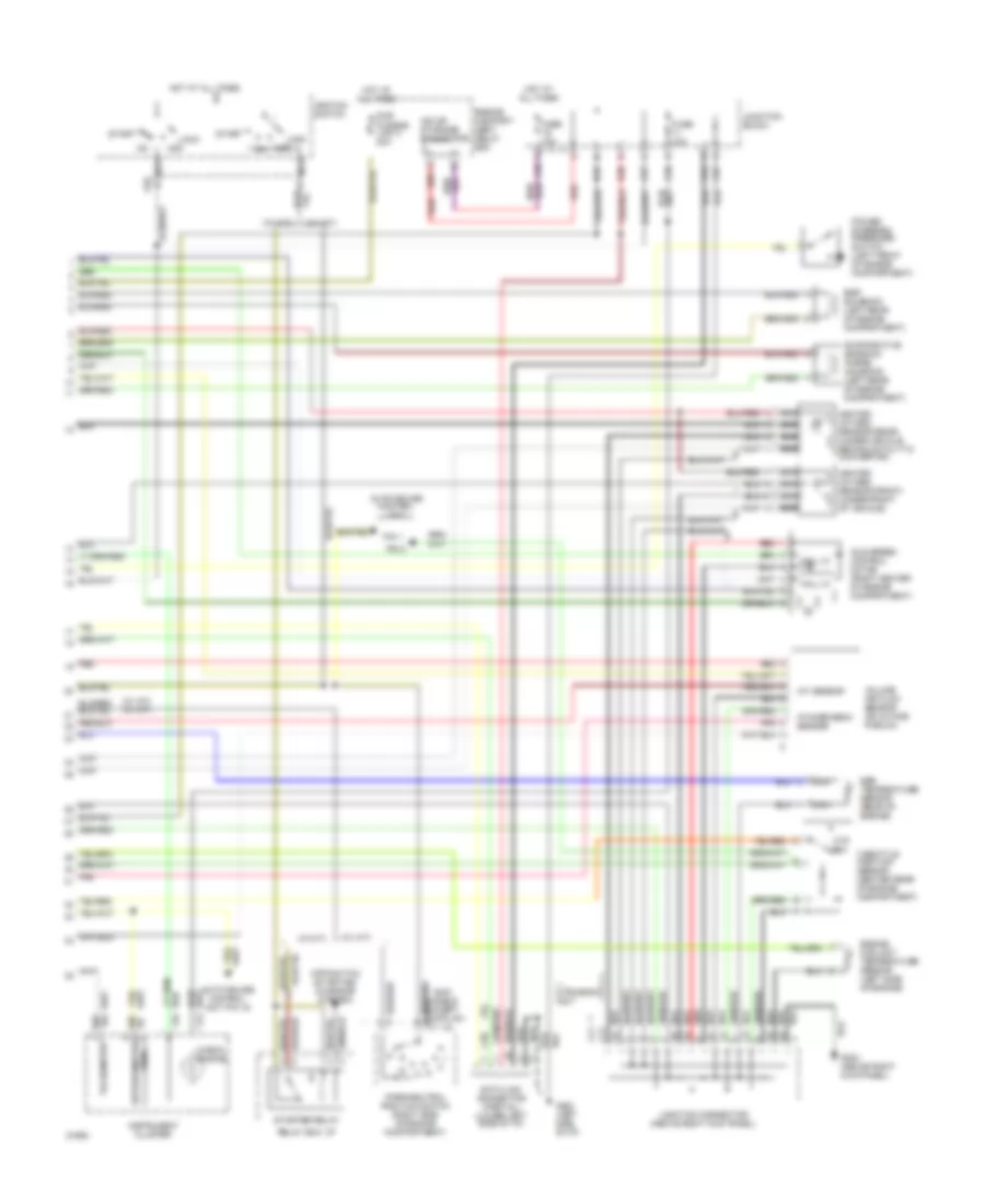
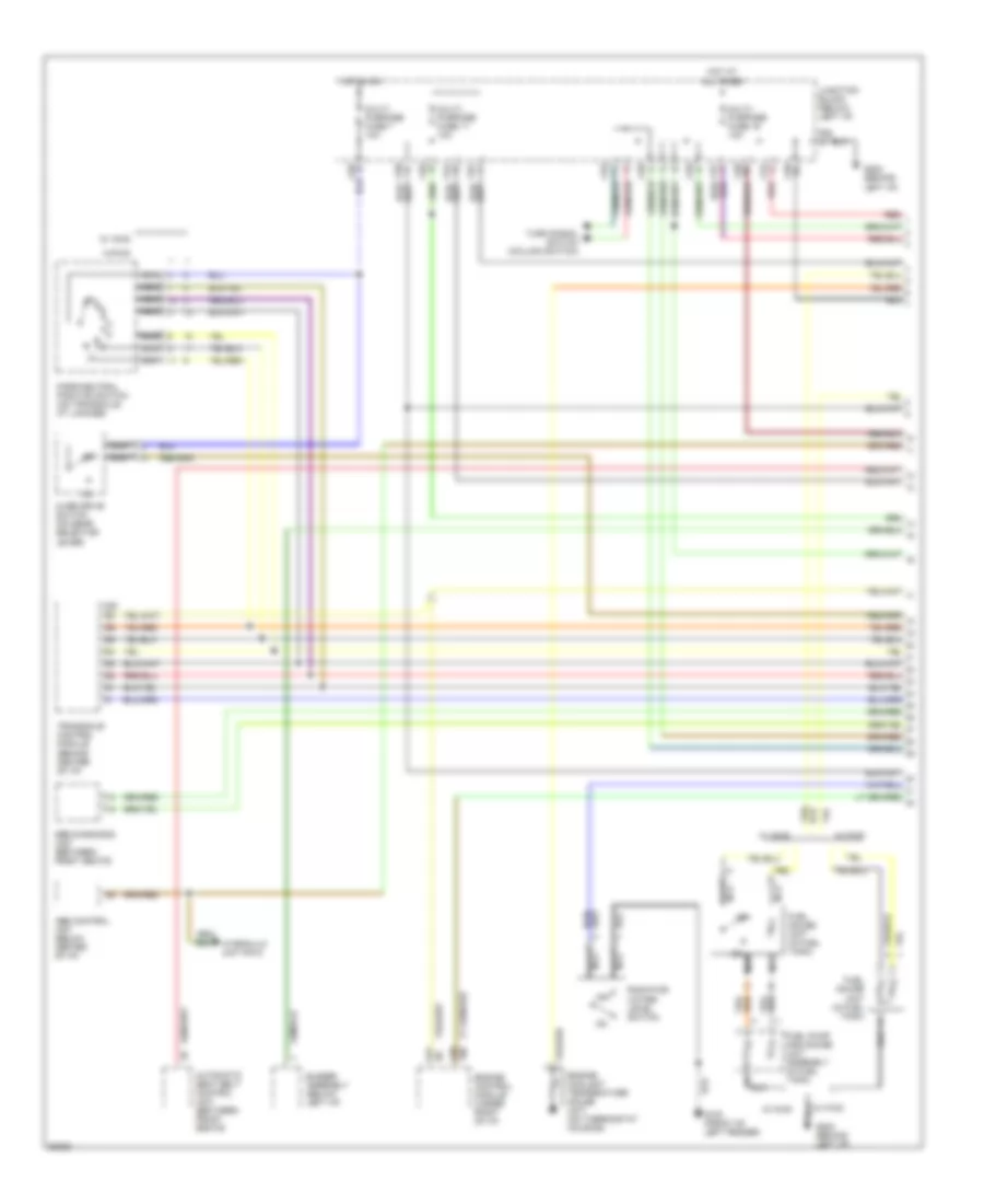
1.8L 1.8L, Engine Performance Wiring Diagrams (1 of 2) for Mitsubishi Expo 1994 List of elements for 1.8L, Engine Performance Wiring Diagrams (1 of 2) for Mitsubishi Expo 1994: 44 (above right kick panel) (w/ a/t) (w/ a/t) (w/ m/t) (w/ m/t) * awd models Air conditioning compressor clutch relay pin 3 Auto-cruise control unit B14 B24 C19 C20 C21 C24 C25 Ckp sensor Cmp sensor Condenser (center of engine compartment) Dash panel) Distributor Distributor assembly (right side of i/p, under center of dash panel) Elc 4-speed automatic transaxle control module (under center of Engine control module (under right side of dash) Engine speed detection connector (center rear of engine compartment) Exc. mitsubishi w/ 1.8l Fuel injectors (top of engine) Fuel pump and gauge unit assembly (in fuel tank) Fuel pump check connector (center rear of engine compartment) G121 (center of safety wall) G202 (behind left side of i/p) Ignition coil Ignition power transistor Ignition timing adjustment connector (center rear of engine compartment) Multiport fuel injection relay (under right center of dash) Nca No connection Pin 4 Pin 5 Pnk Radiator (& condenser) fan motor relays (lo) Radiator (& condenser) fan motor relays (hi) Red Starter (starting/ charging system) Triple pressure switch pin 1 (air conditioning system) Triple pressure switch pin 4 (a/c system) 1.8L, Engine Performance Wiring Diagrams (2 of 2) for Mitsubishi Expo 1994 List of elements for 1.8L, Engine Performance Wiring Diagrams (2 of 2) for Mitsubishi Expo 1994: 63 (speedometer) reed (w/ a/t) (w/ a/t) (w/ m/t) (w/ m/t) * awd models except expo lrv w/ 1.8l ** mitsubishi only A09 Acc Acc on Atmospheric sensor Auto-cruise control unit Auto-cruise control unit pin 19 C02 C38 C57 C58 C61 C64 C66 C67 C71 C77 Check engine Cpp switch (starting/ charging system) Ctp sw D02 D03 Data link connector (partial) (lower left side of i/p) Egr solenoid (left rear of engine compartment) Egr temperature sensor (rear of engine) Engine compart- ment relay box Engine coolant temperature sensor (left side of engine) Evaporative emission purge solenoid (left rear of engine compartment) Fuse 10a Fusible link 3 20a G202 (left side of i/p) G203 (above right kick panel) Hall ic Heated oxygen sensor (front) (under front of vehicle) Heated oxygen sensor (rear) (under vehicle behind catalytic convertor) Hot at all times Iat sensor Idle speed control motor (right center of engine compartment) Ignition switch Instrument cluster Iod or storage connector Junction block Junction connector (above right kick panel) Lock Nca Park/neutral position switch (right side of engine compartment) Pin 1 Pin 5 Pnk Power steering pressure switch (left front of engine compartment) Red Relay box: i/p Start Starter relay Sub Tachometer Throttle position sensor (center rear of engine compartment) Volume air flow sensor (on intake plenum)
2.4L 2.4L, Engine Performance Wiring Diagrams (1 of 2) for Mitsubishi Expo 1994 List of elements for 2.4L, Engine Performance Wiring Diagrams (1 of 2) for Mitsubishi Expo 1994: 44 (above right kick panel) (w/ a/t) (w/ a/t) (w/ m/t) (w/ m/t) * awd models Air conditioning compressor clutch relay pin 3 Auto-cruise control unit B14 B24 C19 C20 C21 C24 C25 Ckp sensor Cmp sensor Condenser (center of engine compartment) Dash panel) Distributor Distributor assembly (right side of i/p, under center of dash panel) Elc 4-speed automatic transaxle control module (under center of Engine control module (under right side of dash) Engine speed detection connector (center rear of engine compartment) Exc. mitsubishi w/ 1.8l Fuel injectors (top of engine) Fuel pump and gauge unit assembly (in fuel tank) Fuel pump check connector (center rear of engine compartment) G121 (center of safety wall) G202 (behind left side of i/p) Ignition coil Ignition power transistor Ignition timing adjustment connector (center rear of engine compartment) Multiport fuel injection relay (under right center of dash) Nca No connection Pin 4 Pin 5 Pnk Radiator (& condenser) fan motor relays (lo) Radiator (& condenser) fan motor relays (hi) Red Starter (starting/ charging system) Triple pressure switch pin 1 (air conditioning system) Triple pressure switch pin 4 (a/c system) 2.4L, Engine Performance Wiring Diagrams (2 of 2) for Mitsubishi Expo 1994 List of elements for 2.4L, Engine Performance Wiring Diagrams (2 of 2) for Mitsubishi Expo 1994: 63 (speedometer) reed (w/ a/t) (w/ a/t) (w/ m/t) (w/ m/t) * awd models except expo lrv w/ 1.8l ** mitsubishi only A09 Acc Acc on Atmospheric sensor Auto-cruise control unit Auto-cruise control unit pin 19 C02 C38 C57 C58 C61 C64 C66 C67 C71 C77 Check engine Cpp switch (starting/ charging system) Ctp sw D02 D03 Data link connector (partial) (lower left side of i/p) Egr solenoid (left rear of engine compartment) Egr temperature sensor (rear of engine) Engine compart- ment relay box Engine coolant temperature sensor (left side of engine) Evaporative emission purge solenoid (left rear of engine compartment) Fuse 10a Fusible link 3 20a G202 (left side of i/p) G203 (above right kick panel) Hall ic Heated oxygen sensor (front) (under front of vehicle) Heated oxygen sensor (rear) (under vehicle behind catalytic convertor) Hot at all times Iat sensor Idle speed control motor (right center of engine compartment) Ignition switch Instrument cluster Iod or storage connector Junction block Junction connector (above right kick panel) Lock Nca Park/neutral position switch (right side of engine compartment) Pin 1 Pin 5 Pnk Power steering pressure switch (left front of engine compartment) Red Relay box: i/p Start Starter relay Sub Tachometer Throttle position sensor (center rear of engine compartment) Volume air flow sensor (on intake plenum)
EXTERIOR LIGHTS Exterior Light Wiring Diagram for Mitsubishi Expo 1994 List of elements for Exterior Light Wiring Diagram for Mitsubishi Expo 1994: 83 (chrysler) (expo) (left i/p) (mitsubishi) (on transaxle at linkage) * awd models except expo lrv w/ 1.8l engine ** led type or (4) bulbs A/t A01x Anti-lock brakes system Assembly pin 8 B64 Back-up light switch (right side of engine compt) Buzzer C56 C58 C61 C62 C63 C66 C75 C76 Column switch Cruise control system D03 Dedicated fuse 1 10a Dedicated fuse 3 10a Engine compartment relay box (right side of engine compt) Fusible link 4 30a G100 (front of left fender) G101 (front of right fender) G202 (behind left i/p) G202 (left side of i/p) G999 (below left "d" pillar) Hazard switch Head High mounted stop light Hot at all times Hot in on or start Instrument cluster J/c c70 j/c c28-2 Junction block (below left i/p) Left Left backup light Left front position light Left front side marker light Left front turn signal light Left liftgate light Left rear combination light Left rear side marker light Left turn Light Lighting switch M/t Multi- purpose fuse 12 10a Multi- purpose fuse 17 15a Multi- purpose fuse 18 10a Nca Not used Off Park/ neutral position switch Red Red/ Right Right backup light Right front position light Right front turn signal light Right license plate light Right liftgate light (expo) Right rear combination light Right turn Solid state Stop light switch Sub Tail Tail stop light Tail/ stop light Taillight relay Turn signal and hazard flasher unit (right of junction block) Turn signal light Turn signal switch W/ cruise control W/o cruise control
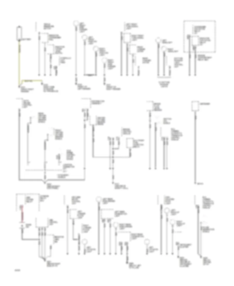
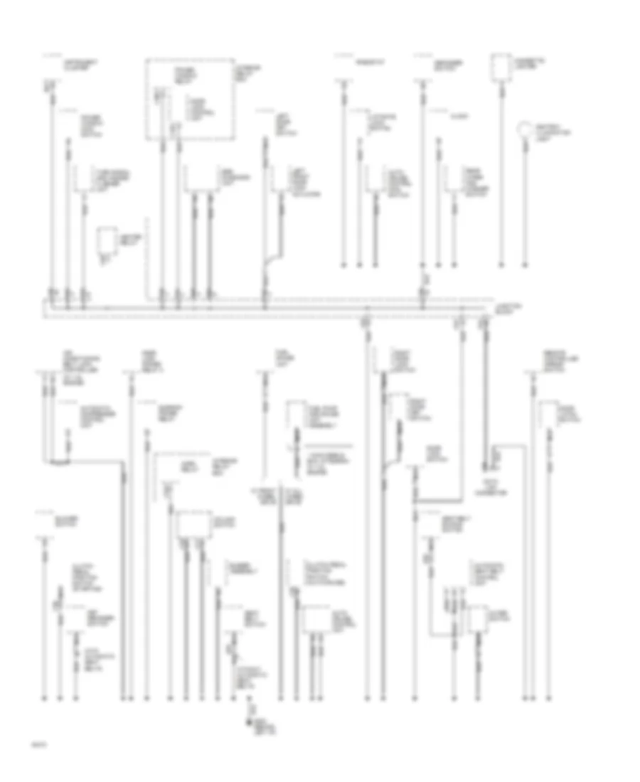
GROUND DISTRIBUTION Ground Distribution Wiring Diagram (1 of 2) for Mitsubishi Expo 1994 List of elements for Ground Distribution Wiring Diagram (1 of 2) for Mitsubishi Expo 1994: 80 * mitsubishi models A05x A08x A27 Abs control unit Abs power relay Auto- cruise control unit B24 Battery Brake fluid level sensor C19 C21 C24 C25 C29x C68 C71 Condenser fan motor relay (hi) D01 Daytime running light control unit Defogger Diode c42 Distributor assembly E52 E53 E58 E59 Elc 4-speed automatic transaxle control module Engine compartment relay box Engine control module Front heated oxygen sensor shield Front washer motor G# n/a G100 (front of left fender) G101 (front of right fender) G101 (front right fender) G120 (right side of engine on transaxle) G121 (center of safety wall) G201 (behind right side of i/p) G202 (behind center of instrument cluster) G203 (above right kick panel) G206 (below center of i/p) G999 (below left "d" pillar) Heated oxygen sensor (rear) High mounted stop light Hydraulic unit (abs) Idle speed control motor shield Ignition coil shield Instrument cluster Interior relay box Junction connector c77 Keyless entry control unit Left back-up light Left front position light Left front side marker light Left front turn signal light Left headlight Left license plate lamp Left liftgate light Left rear combination light Left rear side marker light Multiport fuel injection relay Nca Pulse generator shield Radiator fan motor relay (hi) Radiator water level switch Rear heated oxygen sensor shield Rear washer motor Resistor (abs) Resistor (condenser fan) Right back-up light Right front position light Right front side marker light Right front turn signal light Right headlight Right license plate lamp Right rear combination light Right rear side marker light Triple pressure switch W/ daytime running lights Ground Distribution Wiring Diagram (2 of 2) for Mitsubishi Expo 1994 List of elements for Ground Distribution Wiring Diagram (2 of 2) for Mitsubishi Expo 1994: 68 (w/ 1.8l engine) * awd models exc. mitsubishi w/ 1.8l engine Air conditioning belt lock controller Ashtray illumination light Auto- cruise control main switch Auto- cruise control unit Automatic compressor control unit Automatic seat belt control unit Blower switch Buzzer assembly C30x C32x C34x C35 C36 C38 C58 C59 C61 C62 C63 C64 C67 C74 C76 Cigarette lighter Clock Clutch pedal position switch (auto-cruise) Clutch pedal position switch (starting) Column switch D01 Data link connector Defogger switch Door latch switch Door lock control unit Door lock power relay 2 Door lock switch E70 E78 Fuel gauge unit Fuel pump and gauge unit assembly Heater relay Horn relay Instrument cluster Interior relay box Junction block Key reminder switch Left door key switch Left front door lock actuator Liftgate lock switch Nca Outer switch Power window main switch Power window relay Rear wiper and washer switch Remote controlled mirror switch Rheostat Right door key switch Right door lock switch Seat belt buckle switch Seat belt switch Srs diagnosis unit Sunroof power relay Turn signal and hazard flasher unit W/ all wheel drive W/ front wheel drive With automatic seat belts Without automatic seat belts
HEADLIGHTS Headlight Wiring Diagram for Mitsubishi Expo 1994 List of elements for Headlight Wiring Diagram for Mitsubishi Expo 1994: 24 * mitsubishi models A02x Beam C74 c68 C75 c69 C76 c70 Column switch D01 Dedicated fuse 4 10a Dimmer/ passing switch Engine compartment relay box (right side of engine compartment) G202 (behind left i/p) Head Headlight relay Hot at all times Instrument cluster Left headlight Lighting switch Off Red Right headlight Sub- fusible link 4 30a Tail Taillight relay pin 3 (exterior lights system)
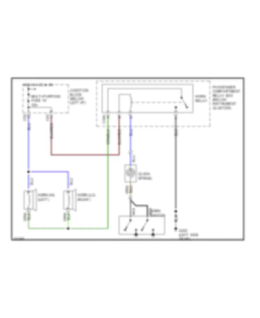
HORN Horn Wiring Diagram for Mitsubishi Expo 1994 List of elements for Horn Wiring Diagram for Mitsubishi Expo 1994: 16 (left) (right) C34x C56 C65 Clock spring G202 (left side of i/p) Horn (hi) Horn (lo) Horn relay Horn switch Hot in acc & on Junction block (below left i/p) Multi-purpose fuse 10 10a Nca Passenger compartment relay box (below instrument cluster)
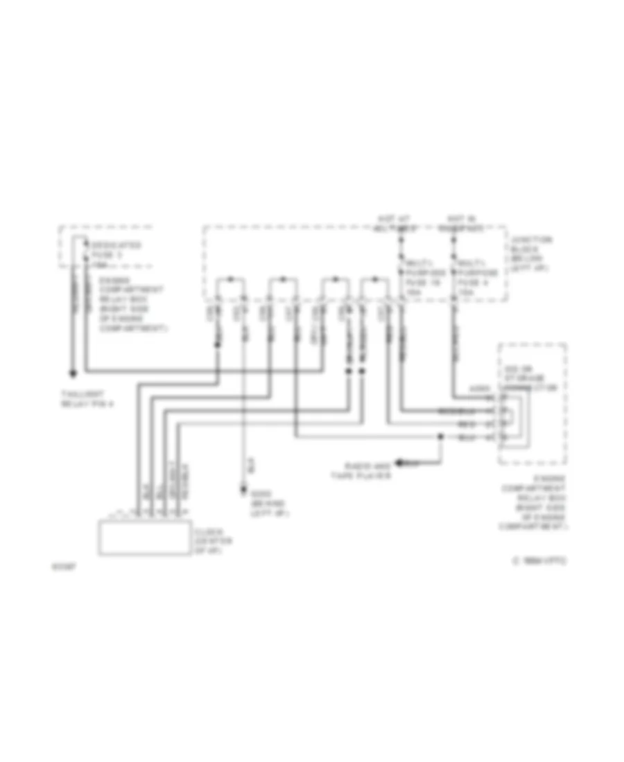
INSTRUMENT CLUSTER Clock Wiring Diagram for Mitsubishi Expo 1994 List of elements for Clock Wiring Diagram for Mitsubishi Expo 1994: 19 1994 vftc c A09x C56 C57 C58 C62 Clock (center of i/p) Dedicated fuse 3 10a Engine compartment relay box (right side of engine compartment) G202 (behind left i/p) Hot at all times Hot in on or acc Iod or storage connector Junction block (below left i/p) Multi- purpose fuse 19 10a Multi- purpose fuse 4 10a Radio and tape player Red Taillight relay pin 4 Gauges & Indicators Wiring Diagram (1 of 2) for Mitsubishi Expo 1994 List of elements for Gauges & Indicators Wiring Diagram (1 of 2) for Mitsubishi Expo 1994: 41 (behind center of i/p) Abs control unit (below center of i/p) Automatic seat belt control unit (between front seats) Buzzer assembly (below left i/p) C20 C21 C25 C56 C57 C58 C61 C62 C63 C65 C66 C67 Engine control module (under right of i/p) Engine coolant temperature gauge unit (on thermostat housing) Fuel gauge unit (in fuel tank) Fuel pump and gauge unit assembly (in fuel tank) G100 (front of left fender) G202 (behind left i/p) Hot at all times Hot in on Hydraulic unit pin 8 Junction block (below left i/p) Multi- purpose fuse 11 10a Multi- purpose fuse 19 10a Multi- purpose fuse 7 10a Nca Off Over drive switch (on gear selector lever) Park/neutral position switch (on transaxle at linkage) Radiator water level switch Red Srs diagnosis unit (between front seats) Transaxle control module Turn signal switch (column switch) W/ awd W/ fwd W/fwd Gauges & Indicators Wiring Diagram (2 of 2) for Mitsubishi Expo 1994 List of elements for Gauges & Indicators Wiring Diagram (2 of 2) for Mitsubishi Expo 1994: 58 A/t temp A06x A09x Abs Acc Auto- cruise control unit (behind left i/p) B16 Beam Brake Brake fluid level sensor (on master cylinder) C43 Charge Check engine Cruise D01 D02 D03 Dedicated fuse 3 10a Dedicated fuse 4 10a Distributor assembly pin 12 Door Engine compartment relay box (right side of engine compartment) Fuel Fuel gauge G121 (rear of engine compartment) G202 (behind center of instrument cluster) Generator Generator relay Headlight relay pin 4 Hot at all times Ignition switch Illumination Instrument cluster Iod or storage connector Left front door switch (interior lights system) Left turn Lock Nca Od off Off Oil Oil pressure switch (right side of engine compartment) Parking brake switch (at parking brake handle) Radiator Red Reed Rheostat pin 2 Right turn Seat belt Speedometer Srs Start Tachometer Taillight relay pin 4 Temperature gauge Upper beam relay pin 4 With automatic seat belts Without automatic seat belts
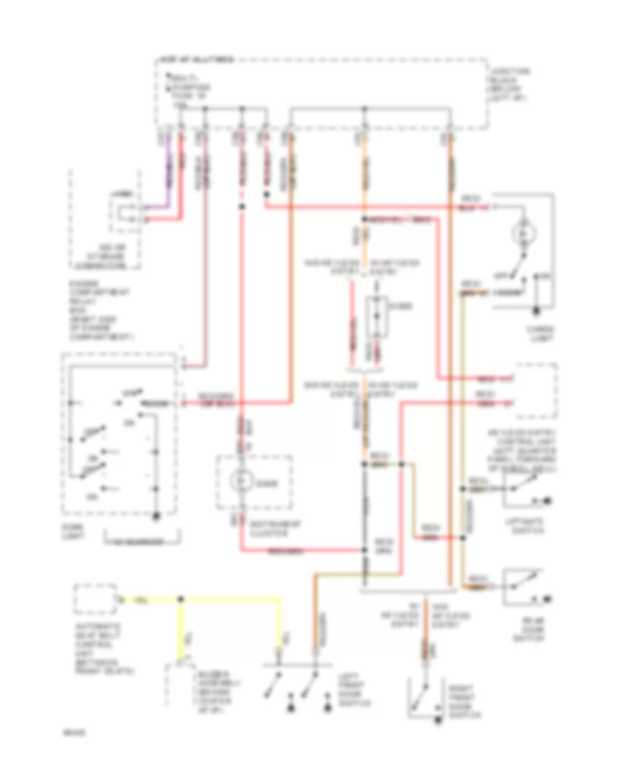
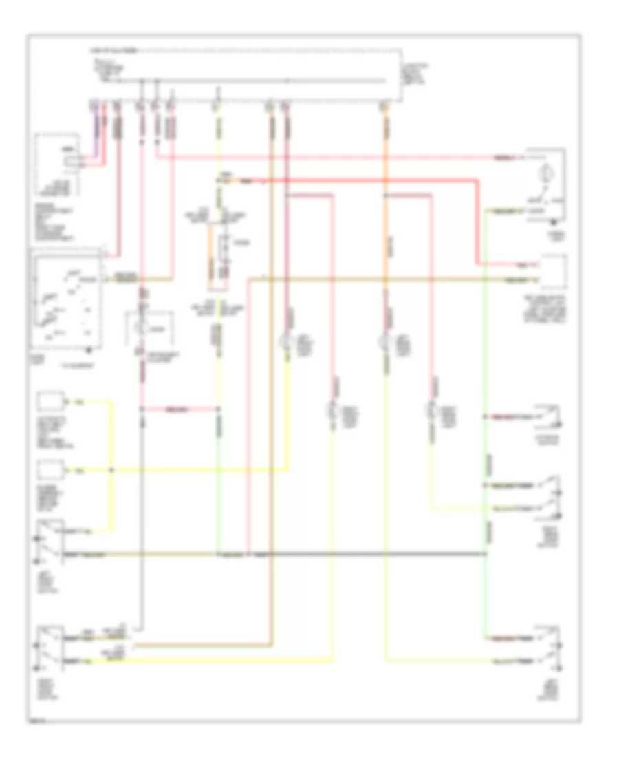
INTERIOR LIGHTS Courtesy Lamp Wiring Diagram, Expo LRV Model Only for Mitsubishi Expo 1994 List of elements for Courtesy Lamp Wiring Diagram, Expo LRV Model Only for Mitsubishi Expo 1994: 33 * w/ sunroof A09x Automatic seat belt control unit (between front seats) Buzzer assembly (behind center of i/p) C57 C58 C60 C61 C66 Cargo light D01 Diode Dome light Door Engine compartment relay box (right side of engine compartment) Entry Hot at all times Instrument cluster Iod or storage connector Junction block (below left i/p) Keyless entry control unit (left quarter panel forward of wheel well) Left front door switch Liftgate switch Multi- purpose fuse 19 10a Nca Off Rear door switch Red Red/ Right front door switch W/ keyless entry W/o keyless entry W/o keyless w/ keyless entry Courtesy Lamp Wiring Diagram, Expo Model Only for Mitsubishi Expo 1994 List of elements for Courtesy Lamp Wiring Diagram, Expo Model Only for Mitsubishi Expo 1994: 39 * w/ sunroof A09x Automatic seat belt control unit (between front seats) Buzzer assembly (behind center of i/p) C57 C58 C60 C61 C63 C66 Cargo light D01 Diode Dome light Door Engine compartment relay box (right side of engine compartment) Hot at all times Instrument cluster Iod or storage connector Junction block (below left i/p) Keyless entry Keyless entry control unit (left quarter panel forward of wheel well) Left front door light Left front door switch Left rear door light Left rear door switch Liftgate switch Multi- purpose fuse 19 10a Nca Off Red Red/ Right front door light Right front door switch Right rear door light Right rear door switch W/ keyless entry W/o keyless entry W/o w/ keyless entry Instrument Illumination Wiring Diagram for Mitsubishi Expo 1994 List of elements for Instrument Illumination Wiring Diagram for Mitsubishi Expo 1994: 35 A01x Ashtray illumination light B62 C56 C58 C61 C64 C75 C76 Cigarette lighter illumination light Clock Column switch D02 D09 Dedicated fuse 3 10a Engine compartment relay box (right side of engine compartment) G202 (left side of i/p) Head Heater control illumination light Hot at all times Illumination Instrument cluster Junction block (below left i/p) Left cluster switch illumination light Nca Od off Off Overdrive switch Radio (or) radio with tape player Rheostat Right cluster switch illumination light Sub fusible link 4 30a Tail Taillight relay Transmissions system
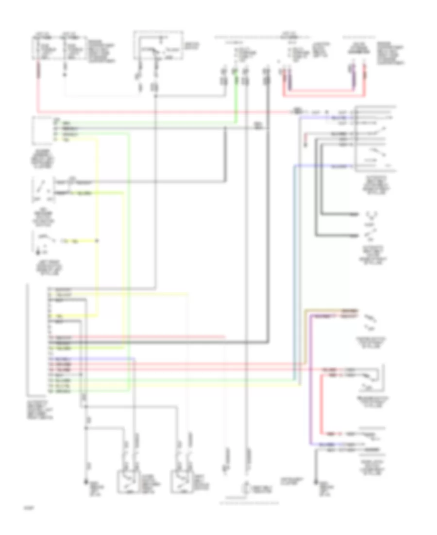
PASSIVE RESTRAINTS Passive Restraint Wiring Diagram for Mitsubishi Expo 1994 List of elements for Passive Restraint Wiring Diagram for Mitsubishi Expo 1994: 42 A09x Acc Automatic seat belt motor (base of right "b" pillar) Automatic seat belt motor relay (base of right "b" pillar) Automatic seatbelt control unit (between front seats) Buzzer assembly (below left instrument cluster) C02 C03 C28 C57 C61 C65 C66 C67 Closed D01 Door latch switch (lower right "b" pillar) Engine compartment relay box (right side of engine compartment) Engine compartment relay box (right side of engine compartment) Fasten switch (top of right "b" pillar) G202 (behind left of i/p) Hot at all times Ignition switch Instrument cluster Iod or storage connector Junction block (below left i/p) Key reminder switch (on ignition switch) Left front door switch (base of left "b" pillar) Lock Multi- purpose fuse 11 10a Multi- purpose fuse 19 10a Nca Off Open Outer switch (between front seats) Red Release switch (top of right "a" pillar) Seat belt buckle switch Seat belt indicator Start Sub fusible link 6 30a Sub fusible link 7 30a
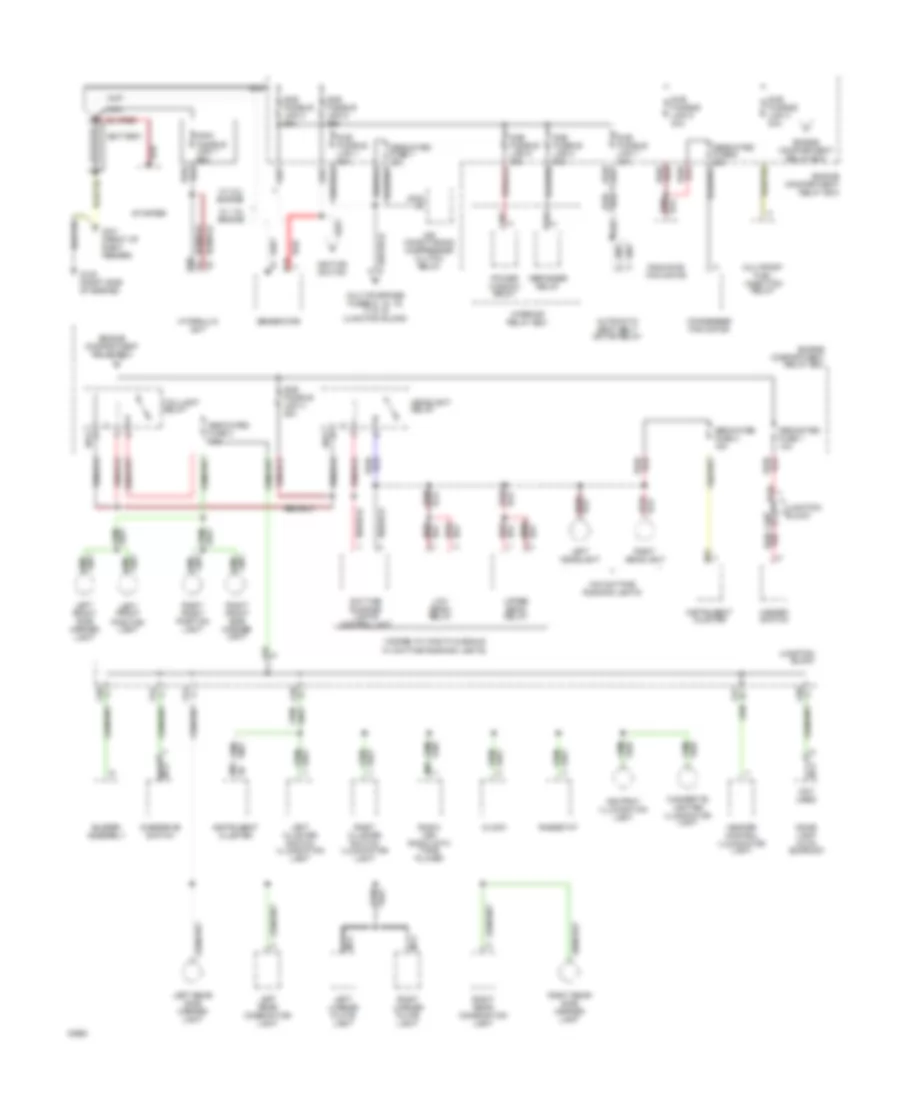
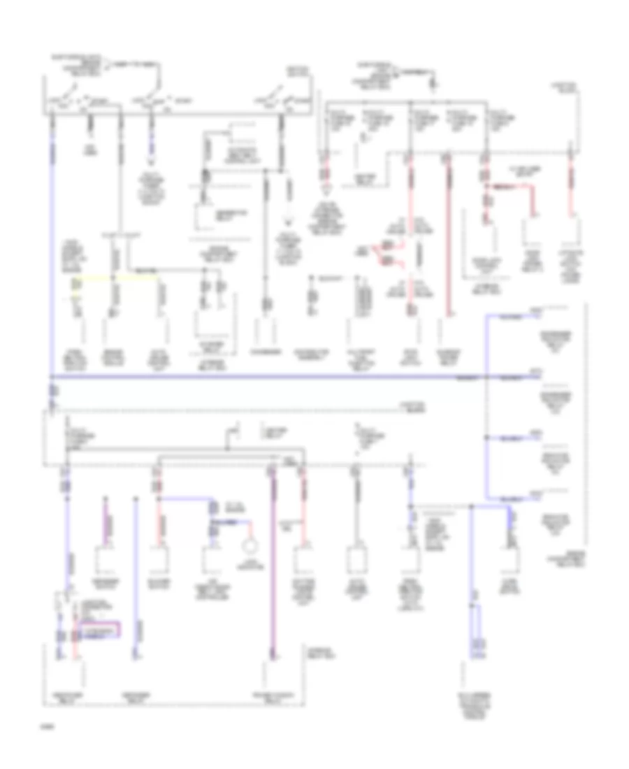
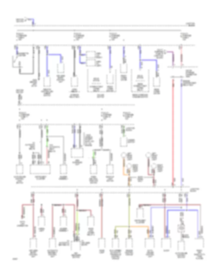
POWER DISTRIBUTION Power Distribution Wiring Diagram (1 of 3) for Mitsubishi Expo 1994 List of elements for Power Distribution Wiring Diagram (1 of 3) for Mitsubishi Expo 1994: 89 ( dodge, plymouth & eagle A01x A02x A03x A26 Air conditioning compressor clutch relay Ashtray illumination light Automatic seat belt motor relay B16 B19 Battery Buzzer assembly C30x C31x C56 C58 C60 C61 C64 C66 Cigarette lighter illumination light Clock Condenser fan motor D01 D02 D09 Daytime running lights control unit Dedicated fuse 1 10a Dedicated fuse 3 10a Dedicated fuse 4 10a Dedicated fuse 6 25a Dedicated fuse 7 10a Defogger relay Dome light (with sunroof) Engine compartment relay box G101 (front of right fender) G120 (right side of engine) Generator Hazard switch Headlight relay Heater control illumination light Hydraulic unit Ignition switch Instrument cluster Interior relay box Junction block Left cluster switch illumination light Left front position light Left front side marker light Left headlight Left license plate light Left rear combination light Left rear side marker light Low beam relay Main fusible link 1 60a Multi-purpose fuses 6, 15. 16, 17 & 19 (junction block) Multiport fuel injection relay Nca Nca not used Overdrive switch Power window relay Radiator fan motor Radio (or) radio with tape player Red Red/ Rheostat Right cluster switch illumination light Right front position light Right front side marker light Right headlight Right license plate light Right rear combination light Right rear side marker light Starter Sub fusible link 1 60a Sub fusible link 2 80a Sub fusible link 3 30a Sub fusible link 4 30a Sub fusible link 5 30a Sub fusible link 6 30a Sub fusible link 7 30a Sub fusible link 8 30a Sub fusible link 9 30a Taillight relay Upper beam relay W/ 1.8l engine W/ 2.4l engine W/ daytime running lights) W/o daytime running lights Power Distribution Wiring Diagram (2 of 3) for Mitsubishi Expo 1994 List of elements for Power Distribution Wiring Diagram (2 of 3) for Mitsubishi Expo 1994: 86 * awd models except expo lrv w/ 1.8l engine ** mitsubishi models A04x A05x A06x A07x A08x Abs power relay Acc Air conditioning belt lock controller Auto- cruise Auto- cruise control unit Automatic seat belt control unit B14 B27 B41x Blower switch C30x C31x C32x C33x C55 C56 C57 C59 C60 C61 C63 C64 C65 C66 C67 Condenser Condenser fan motor relay (hi) Condenser fan motor relay (lo) Daytime running lights control unit Defogger relay Defogger switch Distributor assembly Door lock control unit Door lock power relay 2 Elc 4-speed automatic transaxle control module Engine compartment relay box Engine control module Generator relay Heater relay Ignition switch Interior relay box Iod or storage connector (engine compartment relay box) Junction block Junction connector c70 c28-2 Liftgate lock switch (w/o power locks) Lock Lock indicator Multi- purpose fuse 15 20a Multi- purpose fuse 16 30a Multi- purpose fuse 17 15a Multi- purpose fuse 19 10a Multi- purpose fuse 3 10a Multi- purpose fuse 6 15a Multi- purpose fuse 7 10a Multi- purpose fuses 11,12 & 18 (junction block) Multi- purpose fuses 4, 5, 9 & 10 (junction block) Multiport fuel injection relay Nca Not used Over drive switch Park/ neutral position switch Park/ neutral position switch (with 4 spd a/t) Power window relay Radiator fan motor relay (hi) Radiator fan motor relay (lo) Relay box) Start Starter relay Stop light switch Sub fusible link 1 (engine compartment relay box) Sub fusible link 6 (engine compartment a Sunroof power relay W/ 1.8l engine W/ a/t W/ auto- cruise W/ keyless entry W/ m/t W/o With drl Power Distribution Wiring Diagram (3 of 3) for Mitsubishi Expo 1994 List of elements for Power Distribution Wiring Diagram (3 of 3) for Mitsubishi Expo 1994: 85 * awd models except expo lrv w/ 1.8l engine Auto- cruise control unit Auto-cruise control main switch Auto-cruise control switch Automatic seatbelt control unit Back-up light switch Belts Buzzer assembly C03 C21 C25 C34x C38 C56 C57 C58 C60 C61 C62 C63 C64 C65 C66 C67 C73 Cargo light Clock Clock spring Column switch D01 D03 Data link connector Dome light Door lock power relay 2 E80 Elc 4-speed automatic transaxle control module Engine compartment relay box Engine control module Expo model only Front wiper motor Front wiper switch G202 (behind left of i/p) Gigarette lighter Hazard switch Horn (hi) (left) Horn (lo) (right) Horn relay Ignition d switch Ignition switch Instrument cluster Interior relay box Intermittent wiper relay Iod or storage connector a09x Junction block Key reminder switch Keyless entry control unit Left front door light Left rear door light Multi- purpose fuse 10 10a Multi- purpose fuse 11 10a Multi- purpose fuse 12 10a Multi- purpose fuse 18 10a Multi- purpose fuse 19 (junction block) Multi- purpose fuse 4 10a Multi- purpose fuse 5 15a Multi- purpose fuse 9 15a Nca Park/ neutral position switch Radio (or) radio with tape player Rear intermittent wiper relay Rear wiper and washer switch Rear wiper motor Red Red/ Remote controlled mirror switch Right front door light Right rear door light Solid state Srs diagnosis unit W/ a/t W/ automatc seat belts W/ automatic seatbelts W/ keyless entry W/ m/t W/o automatic seat
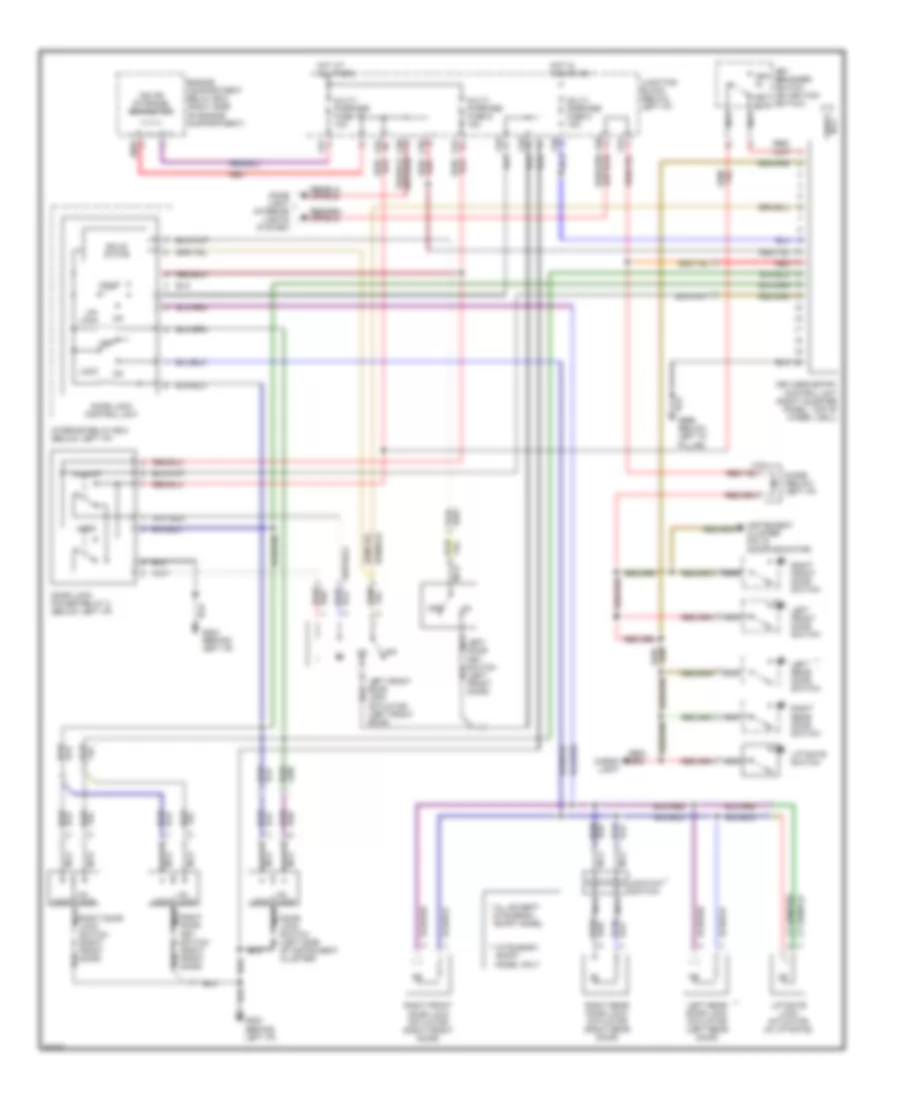
POWER DOOR LOCKS Door Lock Wiring Diagram for Mitsubishi Expo 1994 List of elements for Door Lock Wiring Diagram for Mitsubishi Expo 1994: 28 "expo" model * all except mitsubishi ** mitsubishi "expo" model only C62 C64 Contact switch Door lock control unit Door lock switch (left side of instrument cluster) G202 (behind left i/p) Hot at all times Interior relay box (below left i/p) Junction block (below left i/p) Key switch (right front door) Left door key switch (left front door) Left front door lock actuator (left front door) Left rear door lock actuator (left rear door) Liftgate lock actuator (in liftgate) Lock Multi- purpose fuse 6 15a Nca Off Right door Right door lock switch (right front door) Right front door lock actuator (right front door) Right rear door lock actuator (right rear door) Solid state Un lock Un- lock Keyless Entry Wiring Diagram for Mitsubishi Expo 1994 List of elements for Keyless Entry Wiring Diagram for Mitsubishi Expo 1994: 55 * all except mitsubishi "expo" model ** mitsubishi "expo" model only A09x C57 C60 C61 C62 C64 C66 C72 Cargo light Contact switch Diode (below left i/p) Dome light (interior lights system) Door lock control unit Door lock power relay 2 (below left i/p) Door lock switch (left side of instrument cluster) Engine compartment relay box (right side of engine compartment) G202 (behind left i/p) Hot at all times Hot in acc or on Instrument cluster pin 15 (door indicator) Interior relay box (below left i/p) Iod or storage connector Junction block (below left i/p) Key in Key out Key reminder switch (on ignition switch) Key switch (right front door) Keyless entry control unit (right quarter panel, top of wheel well) Left door key switch (left front door) Left front door lock actuator (left front door) Left front door switch Left rear door lock actuator (left rear door) Left rear door switch Liftgate lock actuator (in liftgate) Liftgate switch Lock Multi- purpose fuse 19 10a Multi- purpose fuse 5 15a Multi- purpose fuse 6 15a Nca Off Red Red/ Right door Right door lock switch (right front door) Right front door lock actuator (right front door) Right front door switch Right rear door lock actuator (right rear door) Right rear door switch Solid state Un lock Un- lock Unlock Power Tailgate Lock Wiring Diagram, without Power Locks for Mitsubishi Expo 1994 List of elements for Power Tailgate Lock Wiring Diagram, without Power Locks for Mitsubishi Expo 1994: 16 All exc. mitsubishi type b C32x C58 C62 C64 G202 (behind left i/p) Hot at all times Junction block (below left i/p) Junction connector (in interior relay box) Liftgate lock actuator (base of lifgate) Liftgate lock switch (on instrument cluster) Lock Mitsubishi type b only Multi- purpose fuse 6 15a Off Unlock
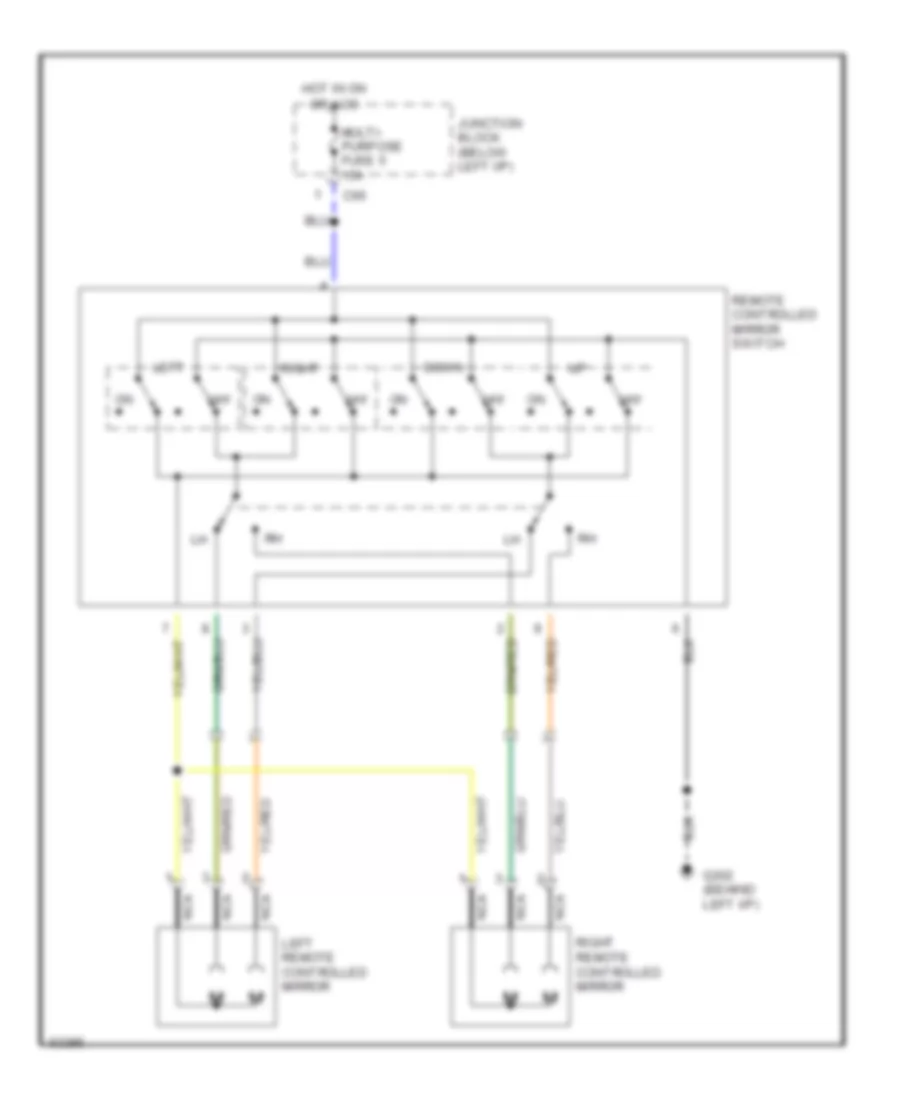
POWER MIRRORS Power Mirror Wiring Diagram for Mitsubishi Expo 1994 List of elements for Power Mirror Wiring Diagram for Mitsubishi Expo 1994: 13 C66 Down G202 (behind left i/p) Hot in on or acc Junction block (below left i/p) Left Left remote controlled mirror Multi- purpose fuse 5 15a Nca Off Remote controlled mirror switch Right Right remote controlled mirror
POWER TOP/SUNROOF Sunroof Wiring Diagram for Mitsubishi Expo 1994 List of elements for Sunroof Wiring Diagram for Mitsubishi Expo 1994: 28 (behind left i/p) C56 C60 C61 Close open Dedicated fuse 3 10a Dome light Down up Engine compartment relay box (right side of engine compartment) For timer reset Hot at all times Hot in on Junction block (below left i/p) Limit switch (on motor drive assembly) Multi- purpose fuse 15 20a Multi- purpose fuse 3 10a Nca Open/ close detecting circuit Red Relay 1 Relay 2 Slide Sunroof control relay (front left corner of roof) Sunroof motor Sunroof power relay (front left corner of roof) Sunroof switch Tail light relay pin 4 Tilt
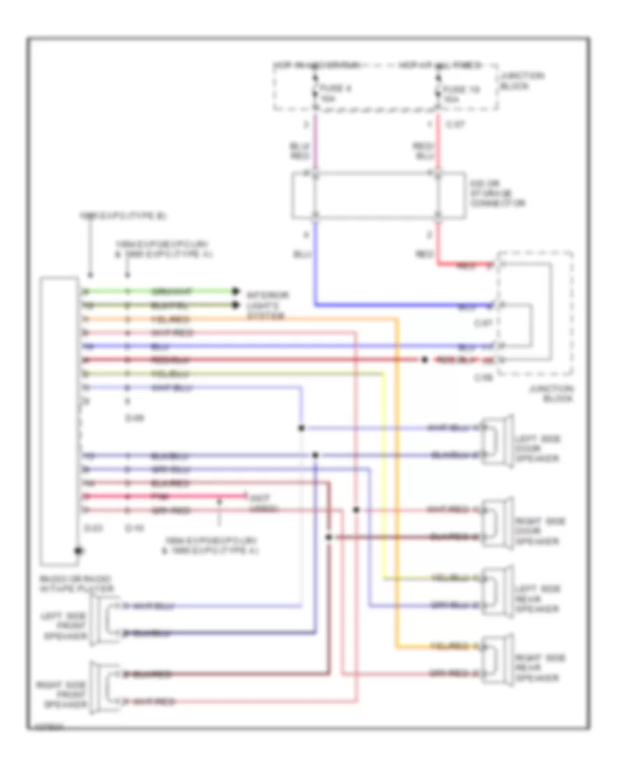
RADIO Radio Wiring Diagrams for Mitsubishi Expo 1994 List of elements for Radio Wiring Diagrams for Mitsubishi Expo 1994: 24 (not used) 1994 expo/expo lrv & 1995 expo (type a) 1995 expo (type b) C-57 C-58 D-09 D-10 D-23 Fuse 19 10a Fuse 4 10a Hot at all times Hot in acc or run Interior lights system Iod or storage connector Junction block Left side door speaker Left side front speaker Left side rear speaker Pnk Radio or radio w/tape player Red Right side door speaker Right side front speaker Right side rear speaker
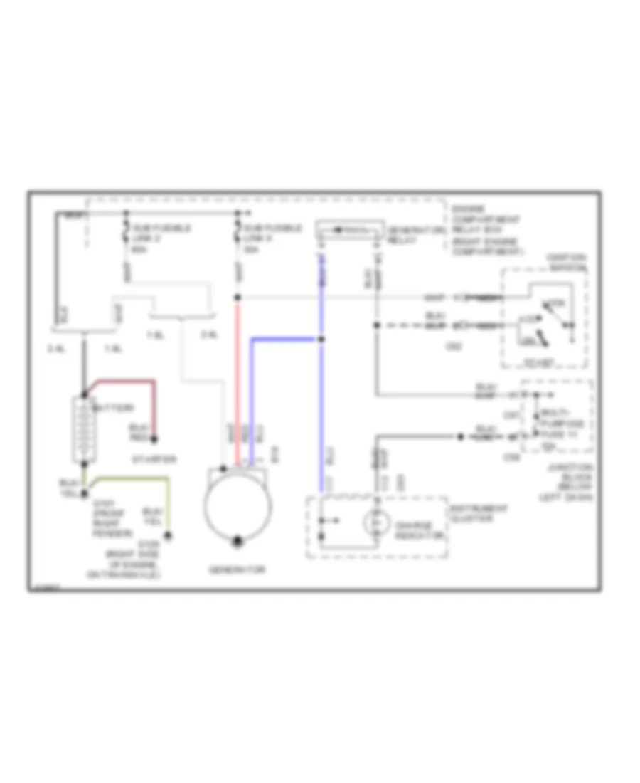
STARTING/CHARGING Charging Wiring Diagram for Mitsubishi Expo 1994 List of elements for Charging Wiring Diagram for Mitsubishi Expo 1994: 30 (right engine compartment) 1.8l 2.4l 30a 80a Acc B16 Battery C02 C58 C67 Charge indicator D03 Engine compartment relay box G101 (front right fender) G120 (right side of engine, on transaxle) Generator Generator relay Ignition switch Instrument cluster Junction block (below left dash) Lock Multi- Nca Purpose fuse 11 10a Red Start Starter Sub fusible link 2 Sub fusible link 6 Starting Wiring Diagram for Mitsubishi Expo 1994 List of elements for Starting Wiring Diagram for Mitsubishi Expo 1994: 29 * with awd exc. 1.8l expo A/t A12 Acc on Auto-cruise control unit pin 1 B19 B20 Battery C02 C33x C36 Clutch pedal position switch (starting) (behind i/p) Engine compt relay box (right engine compt) Engine control module pin 51 Engine control module pin 71 G101 (front right fender) G120 (right side of engine on transaxle) Generator Ignition switch Interior relay box (below instrument cluster) Lock M/t Nca Park/neutral position switch (right engine compartment, at transaxle linkage) Red Start Starter Starter relay Sub fusible link 6 30a
SUPPLEMENTAL RESTRAINTS Supplemental Restraint Wiring Diagram for Mitsubishi Expo 1994 List of elements for Supplemental Restraint Wiring Diagram for Mitsubishi Expo 1994: 31 A09x Air bag module C38 C57 C58 C61 C63 C64 C66 C67 Clock spring Connector lock switch (in srs diagnosis unit connector) D01 D03 Data link connector (below left i/p) E80 E81 Engine compartment relay box (right side of engine compartment) G202 (behind left i/p) Hot at all times Hot in on or start Instrument cluster Iod or storage connector Junction block (below left i/p) Multi- purpose fuse 11 10a Multi- purpose fuse 18 10a Multi- purpose fuse 19 10a Nca Red Srs Srs diagnosis unit (between front seats)
TRANSMISSION Transmission Wiring Diagram for Mitsubishi Expo 1994 List of elements for Transmission Wiring Diagram for Mitsubishi Expo 1994: 61 (inst cluster) (j/b) (side) (top) 1995 vftc c 4-speed a/t solenoid valve A/c comp relay A/c engine coolant temperature switch A/t fluid temperature sensor (on valve body) A/t temp ind Auto cruise ctrl unit pin #1 Autocruise control unit pin #10 Autocruise control unit pin #4 Autocruise ctrl unit pin #11 Autocruise ctrl unit pin #19 Awd Back-up lights C-61 C-66 Data link conn Dedicated fuse #3 (j/b) Elc 4-speed automatic transaxle control module (below center of i/p) Engine control module pin #115 Engine control module pin #51 Engine control module pin #66 Engine control module pin #67 Engine control module pin #71 Fuse #18 (j/b) Fuse #19 10a Fuse #7 (j/b) Fwd G121 (right center of safety wall) G206 (below center of i/p, near a/t control module) Ignition coil Ignition switch Instrument cluster Iod or storage connector J/b Kick-down servo switch (front of transaxle) Models Nca Oil pressure control solenoid valve Overdrive switch (on gear select lever) Park/neutral position switch (on transaxle at linkage) Pin #1 (or 10) Pin #6 Pnk Pulse generators (right side of engine on transaxle) R n Red Reed switch (vss) (inst clstr) Rheostat Shift control solenoid valves Starter motor Throttle position sensor Torque converter clutch solenoid valve Triple pressure switch W/ auto- cruise W/ autocruise W/o auto- cruise W/o autocruise
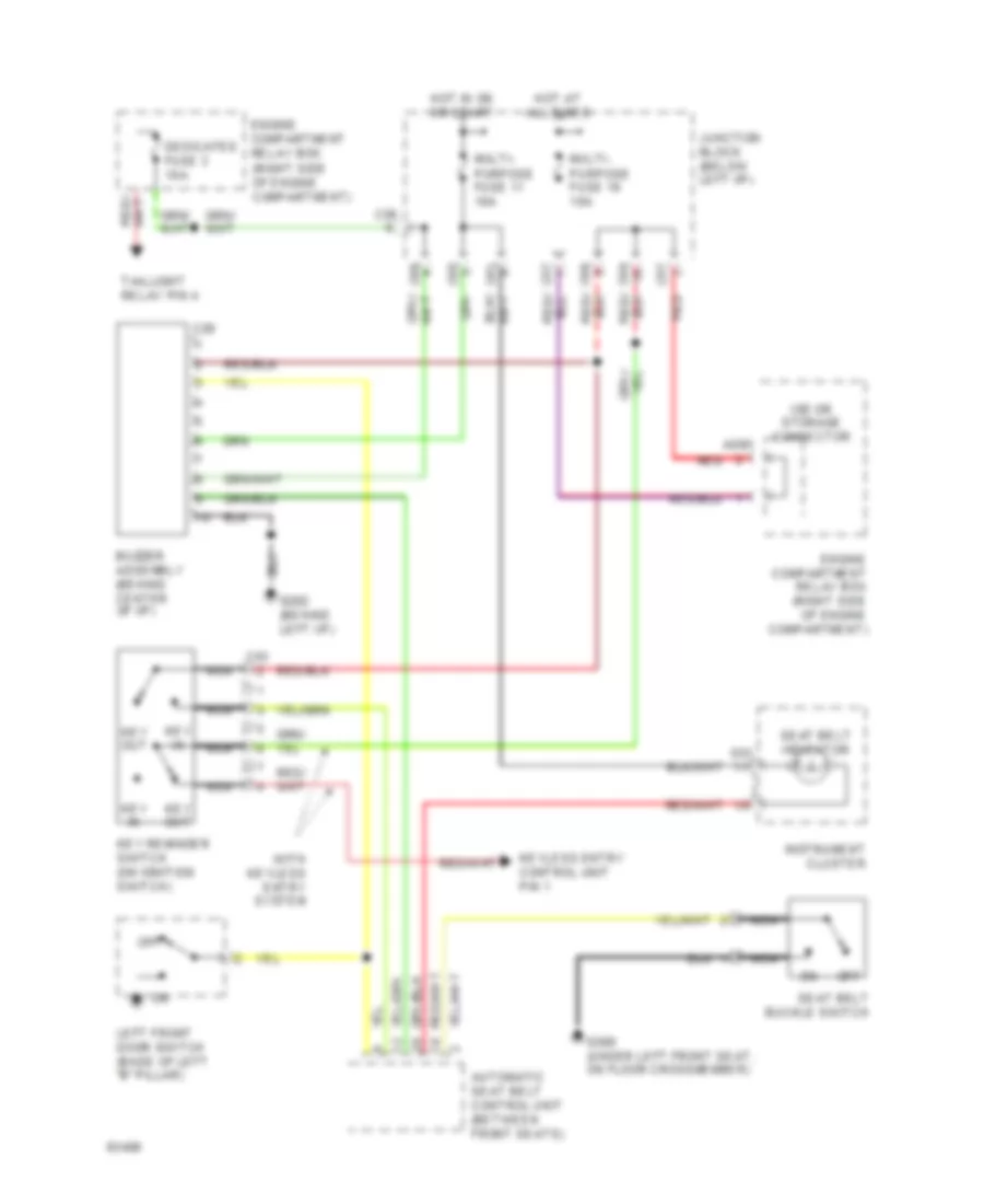
WARNING SYSTEMS Warning System Wiring Diagrams for Mitsubishi Expo 1994 List of elements for Warning System Wiring Diagrams for Mitsubishi Expo 1994: 35 A09x Automatic seat belt control unit (between front seats) Buzzer assembly (behind center of i/p) C03 C28 C56 C57 C61 C64 C65 C66 D01 Dedicated fuse 3 10a Engine compartment relay box (right side of engine compartment) G202 (behind left i/p) G300 (under left front seat, on floor crossmember) Hot at all times Hot in on or start Instrument cluster Iod or storage connector Junction block (below left i/p) Key in Key out Key reminder switch (on ignition switch) Keyless entry control unit pin 1 Left front door switch (base of left "b" pillar) Multi- purpose fuse 11 10a Multi- purpose fuse 19 10a Nca Off Red Seat belt buckle switch Seat belt indicator Taillight relay pin 4 With keyless entry system
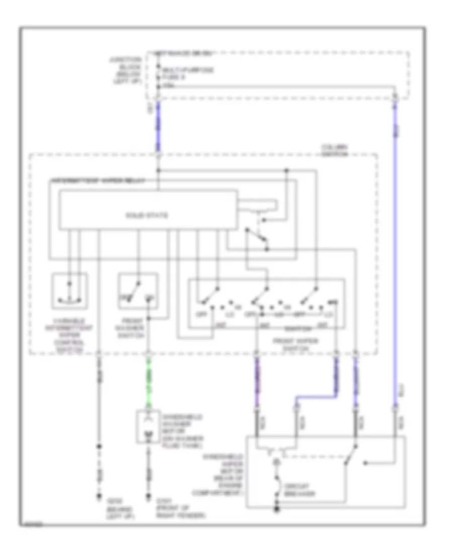
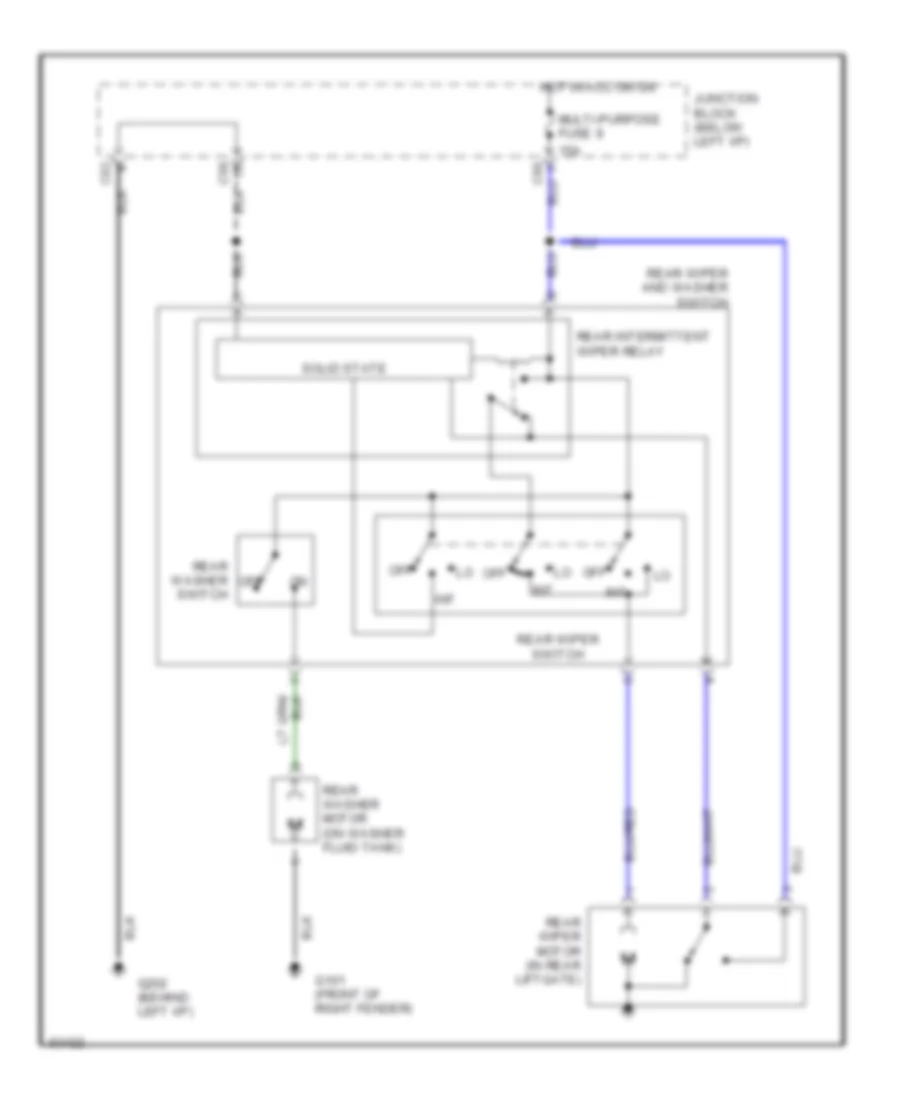
WIPER/WASHER Front Wiper/Washer Wiring Diagram for Mitsubishi Expo 1994 List of elements for Front Wiper/Washer Wiring Diagram for Mitsubishi Expo 1994: 21 (behind left i/p) 15a C67 Circuit breaker Column switch Front washer switch Front wiper switch G101 (front of right fender) G202 Hot in acc or on Int Intermittent wiper relay Junction block (below left i/p) Multi-purpose fuse 9 Nca Off Solid state Switch Variable intermittent wiper control switch Windshield washer motor (on washer fluid tank) Windshield wiper motor (rear of engine compartment) Rear Wiper/Washer Wiring Diagram for Mitsubishi Expo 1994 List of elements for Rear Wiper/Washer Wiring Diagram for Mitsubishi Expo 1994: 18 15a C58 C62 G101 (front of right fender) G202 (behind left i/p) Hot in acc or on Int Junction block (below left i/p) Multi-purpose fuse 9 Off Rear intermittent wiper relay Rear washer motor (on washer fluid tank) Rear washer off Rear wiper and washer switch Rear wiper motor (in rear liftgate) Rear wiper switch Solid state Switch