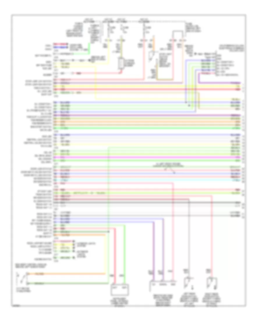
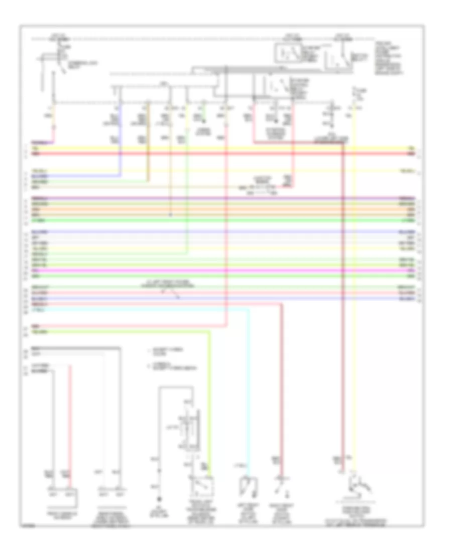
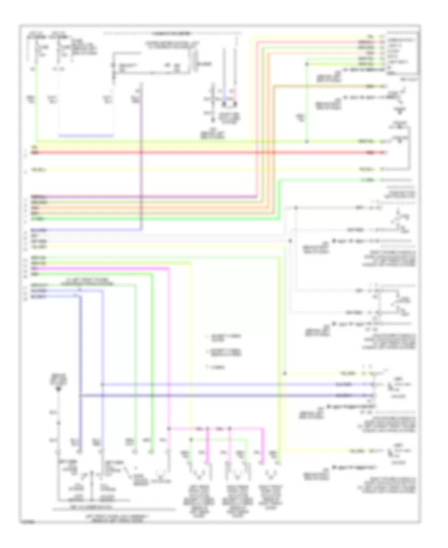
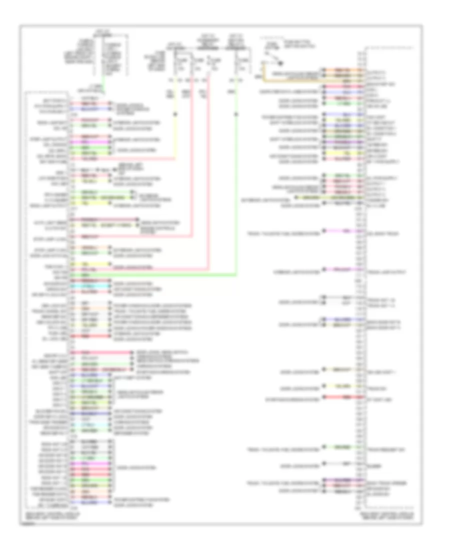
Diagram sections — 31 (110 total)
AIR CONDITIONING ANTI-LOCK BRAKES ANTI-THEFT BODY CONTROL MODULES COMPUTER DATA LINES COOLING FAN CRUISE CONTROL DEFOGGERS ELECTRONIC POWER STEERING ENGINE PERFORMANCE EXTERIOR LIGHTS GROUND DISTRIBUTION HEADLIGHTS HORN INSTRUMENT CLUSTER INTERIOR LIGHTS NAVIGATION POWER DISTRIBUTION POWER DOOR LOCKS POWER MIRRORS POWER SEATS POWER TOP/SUNROOF POWER WINDOWS RADIO SHIFT INTERLOCK STARTING/CHARGING SUPPLEMENTAL RESTRAINTS TRANSMISSION TRUNK, TAILGATE, FUEL DOOR WARNING SYSTEMS WIPER/WASHER
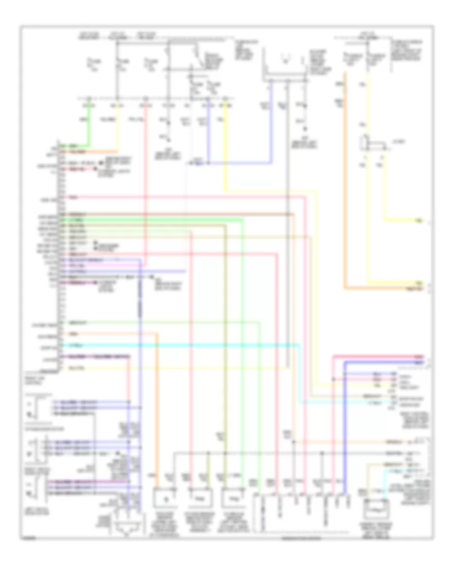
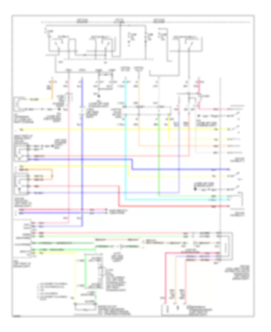
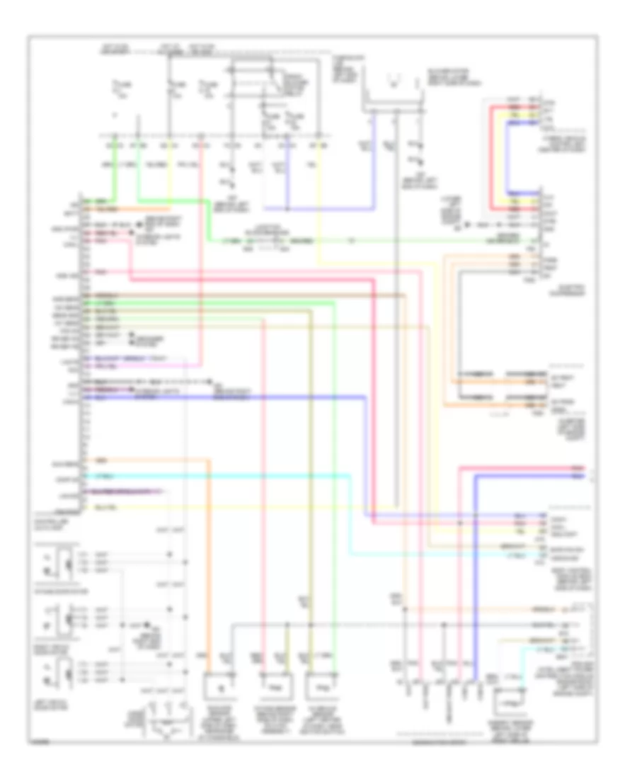
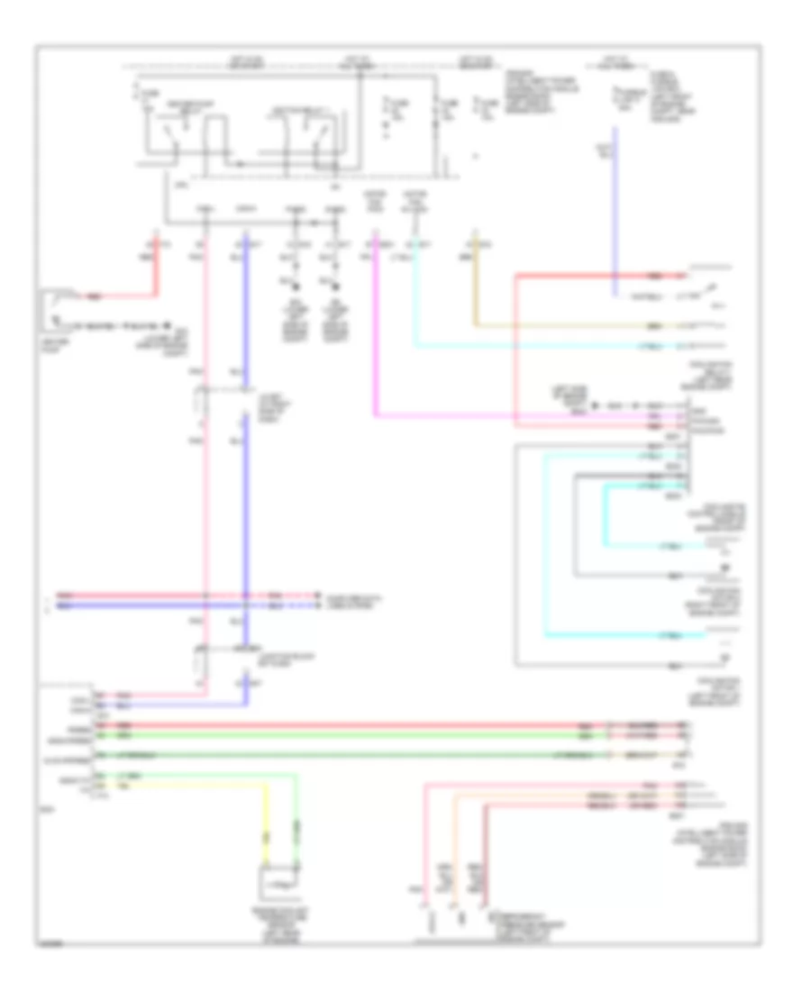
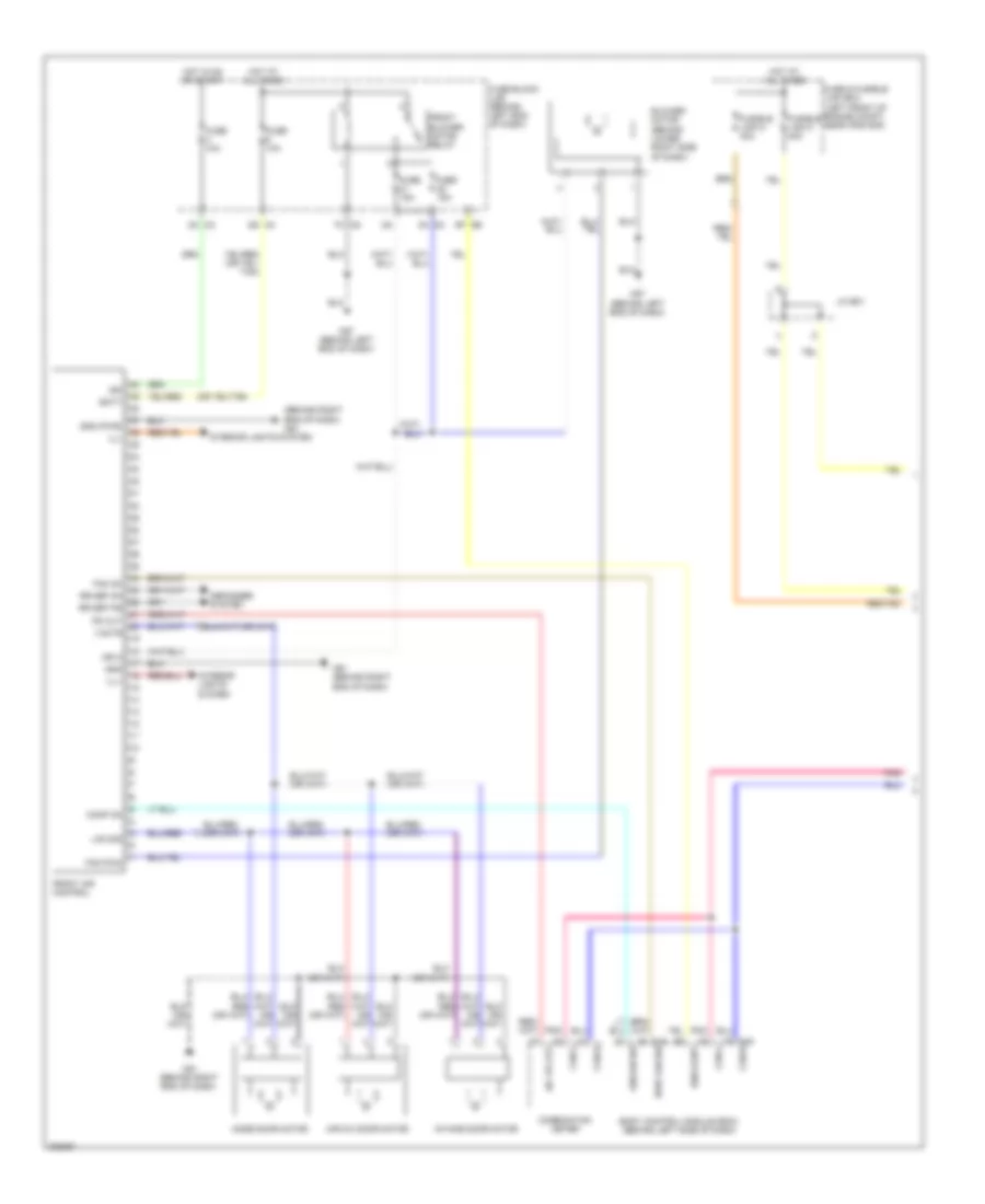
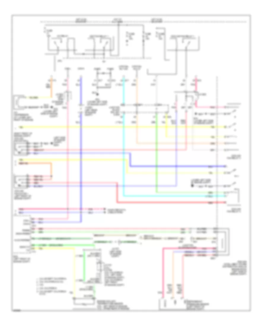
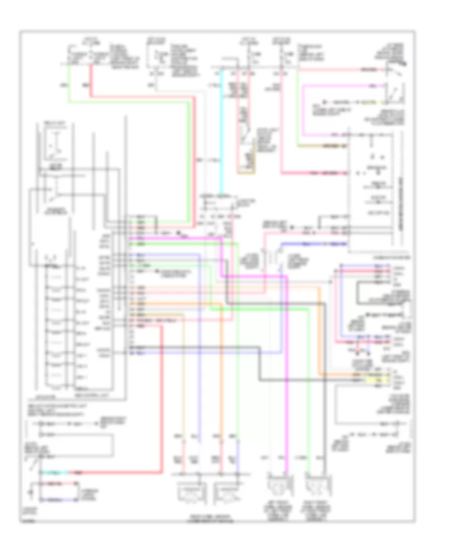
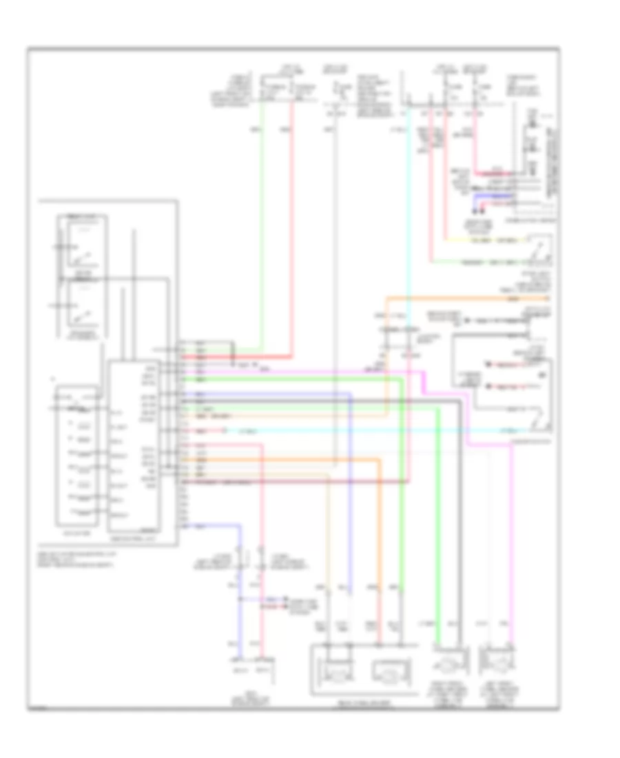
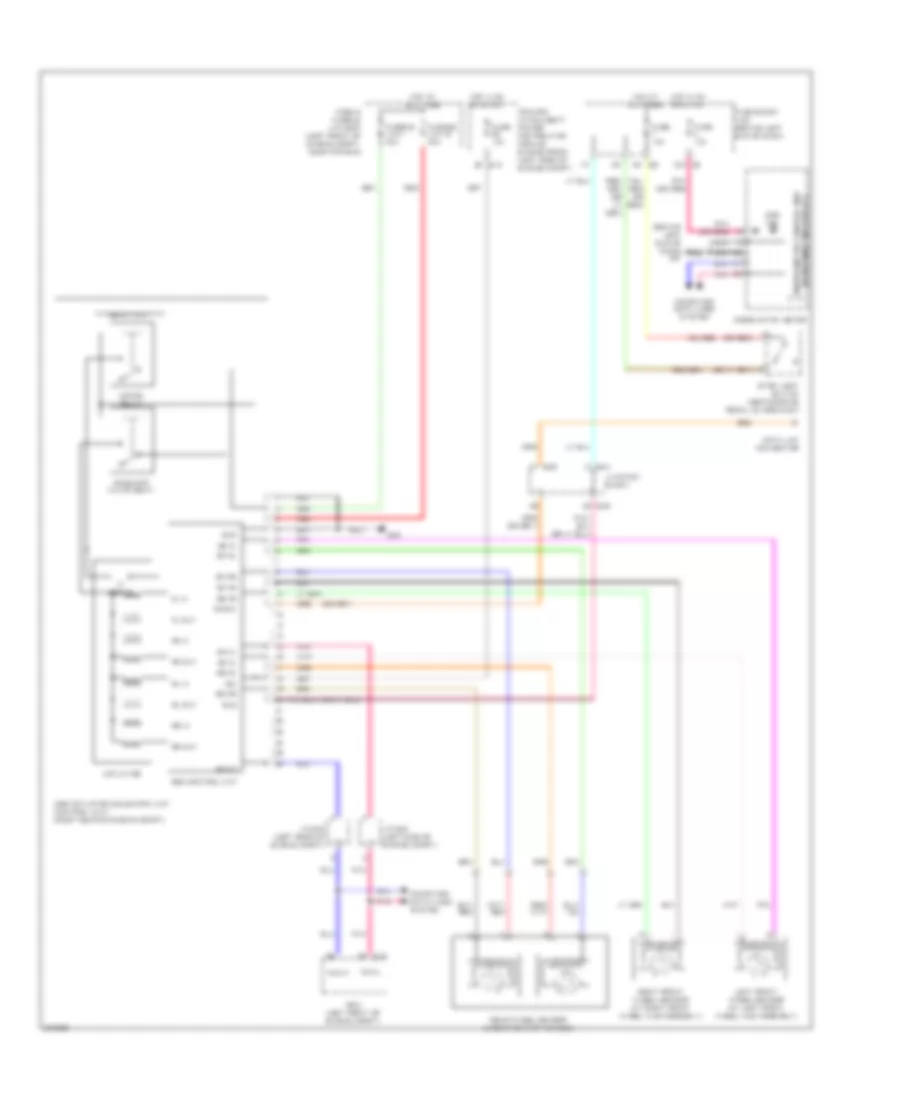
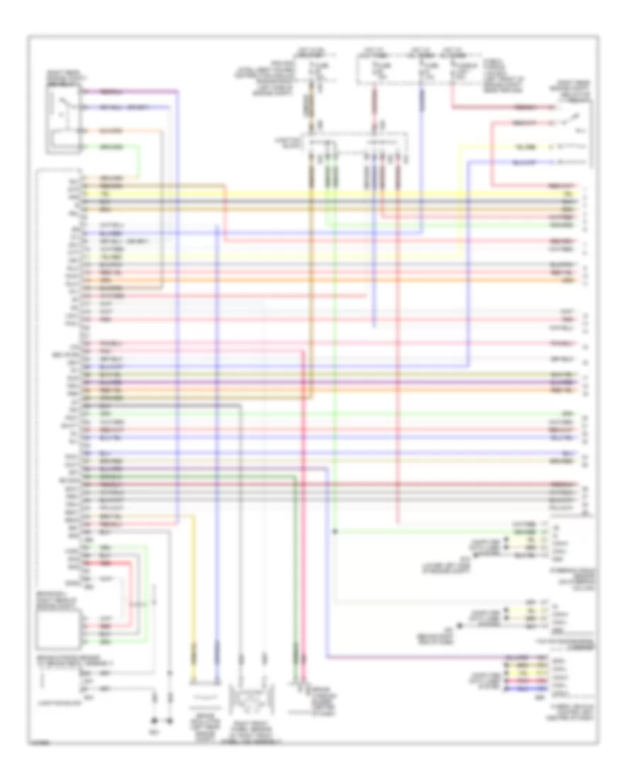
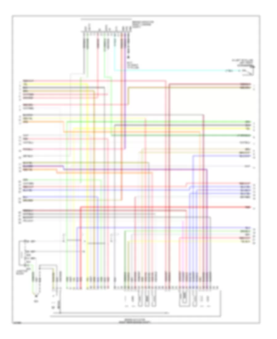
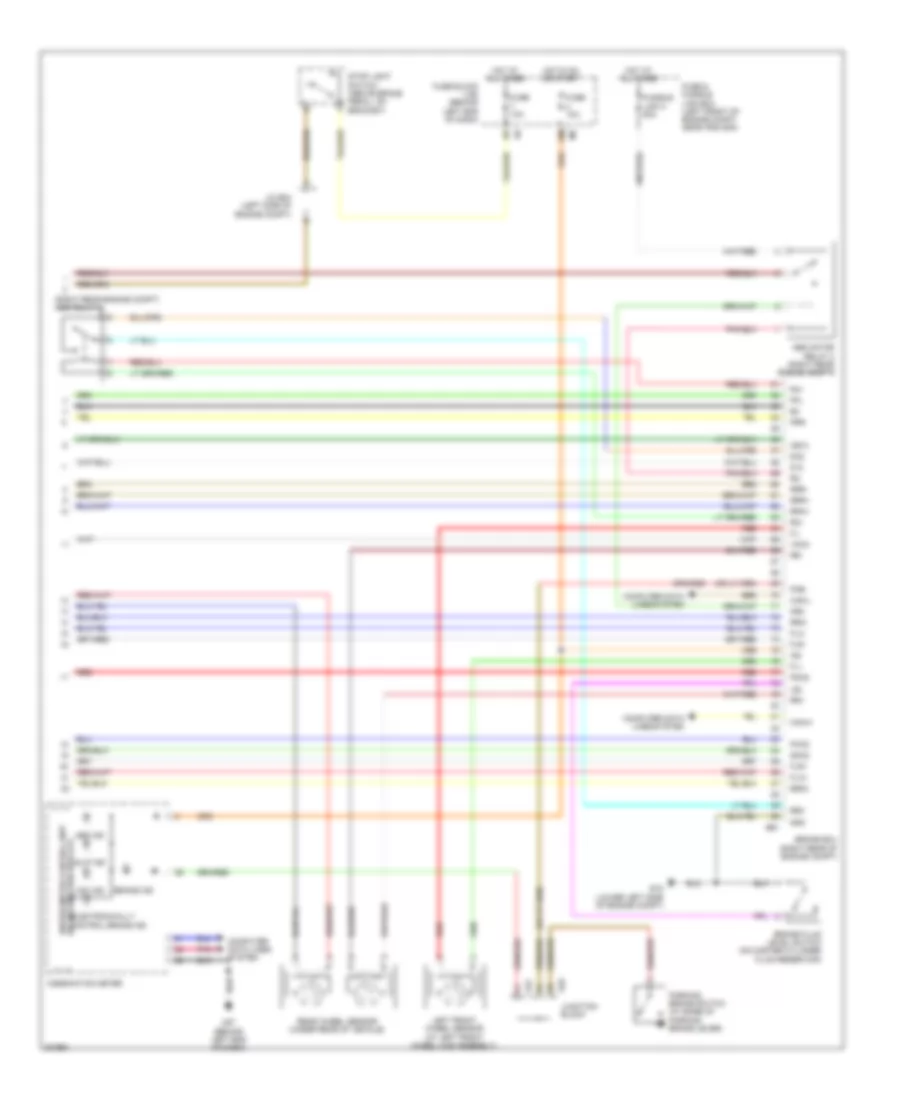
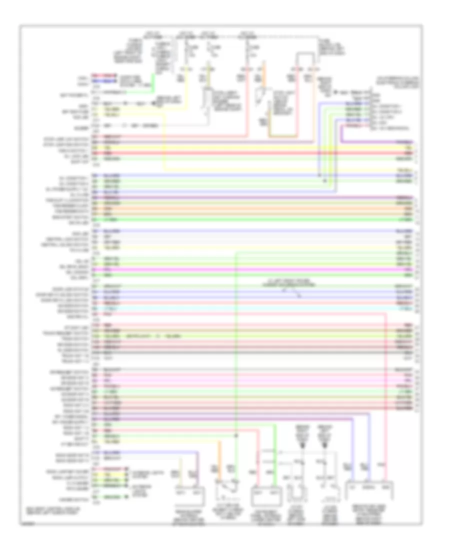
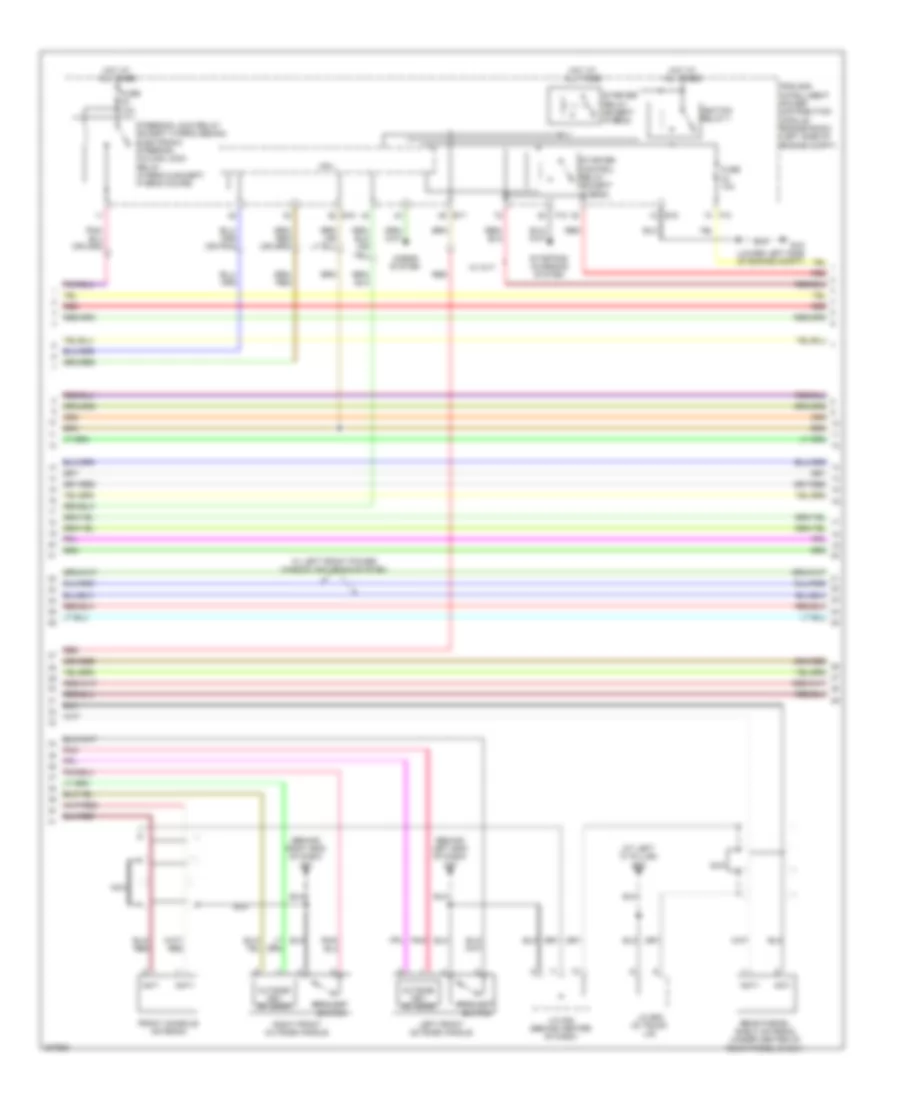
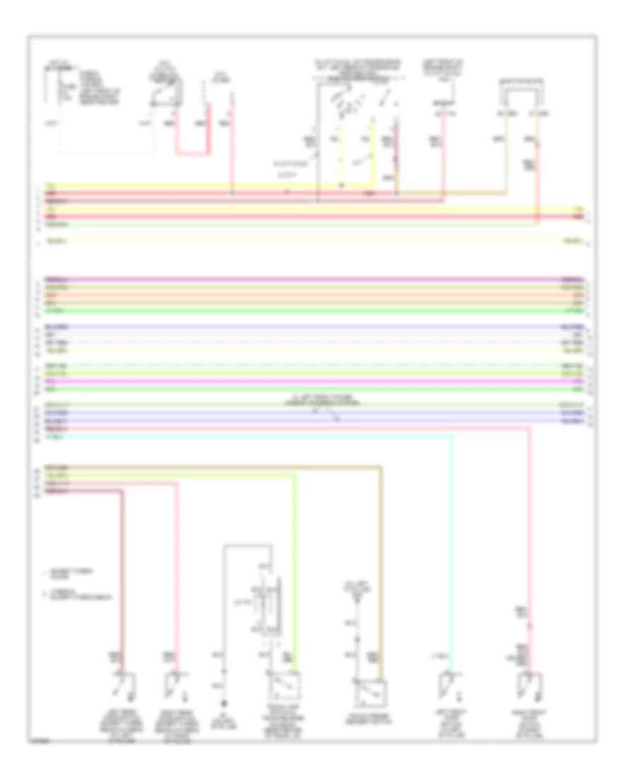
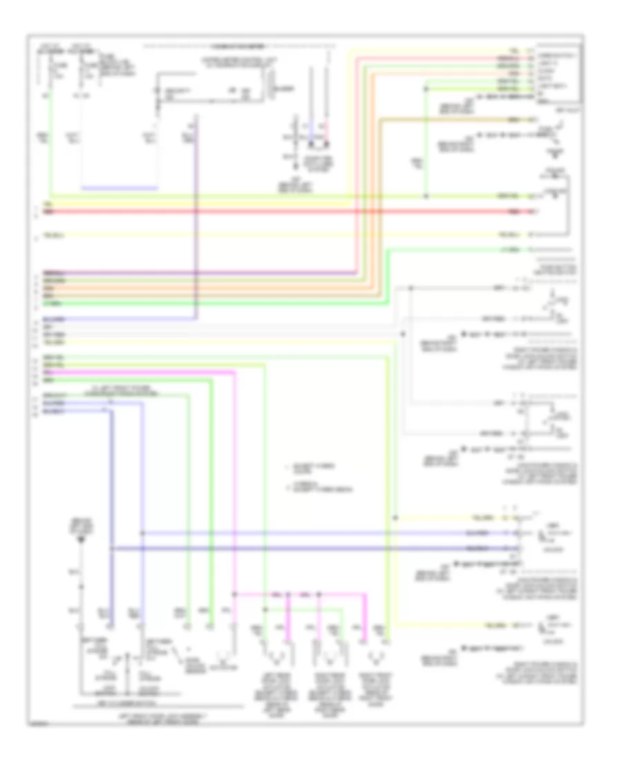
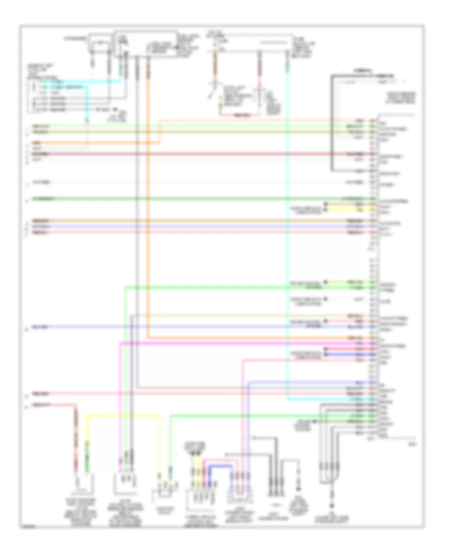
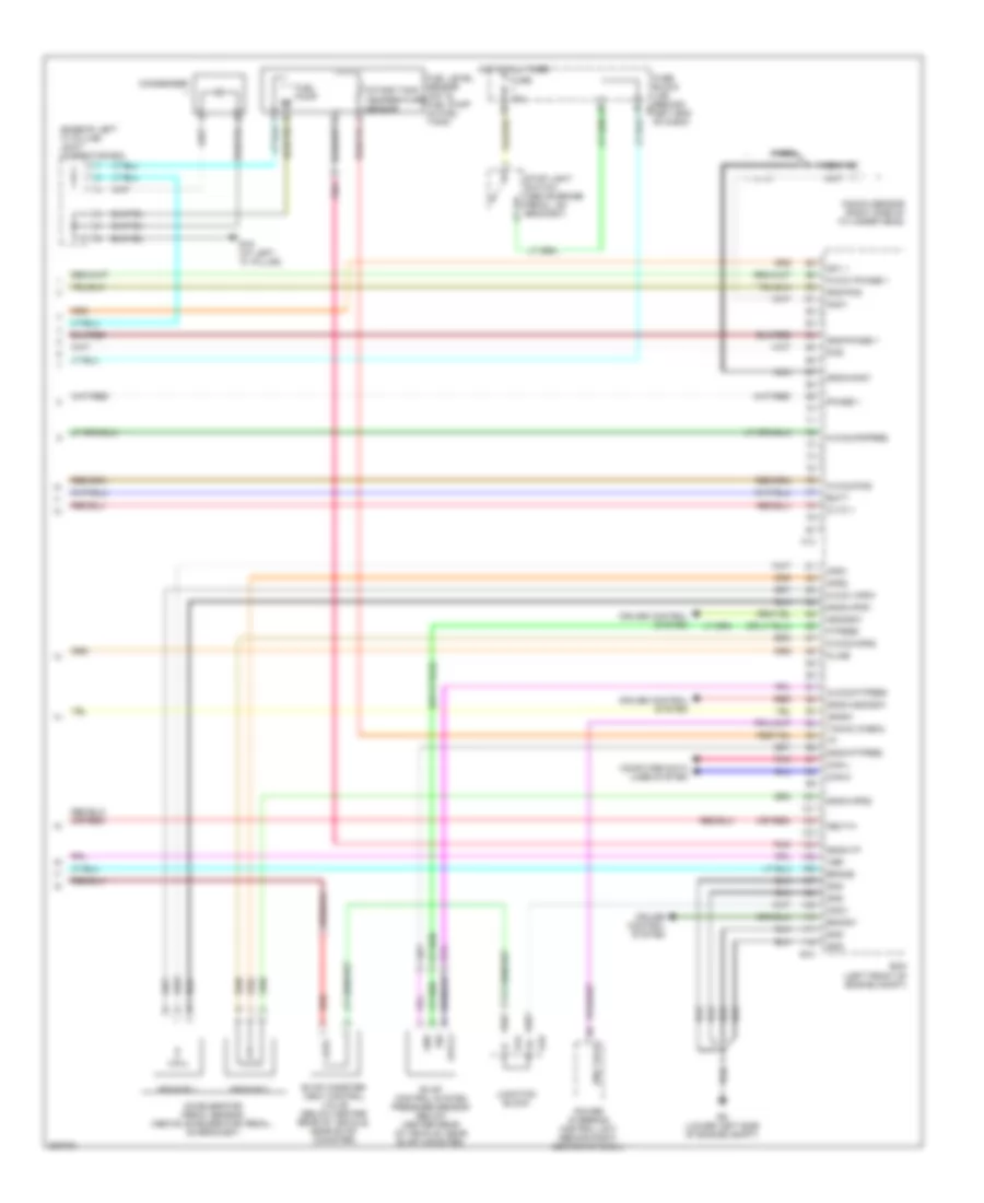
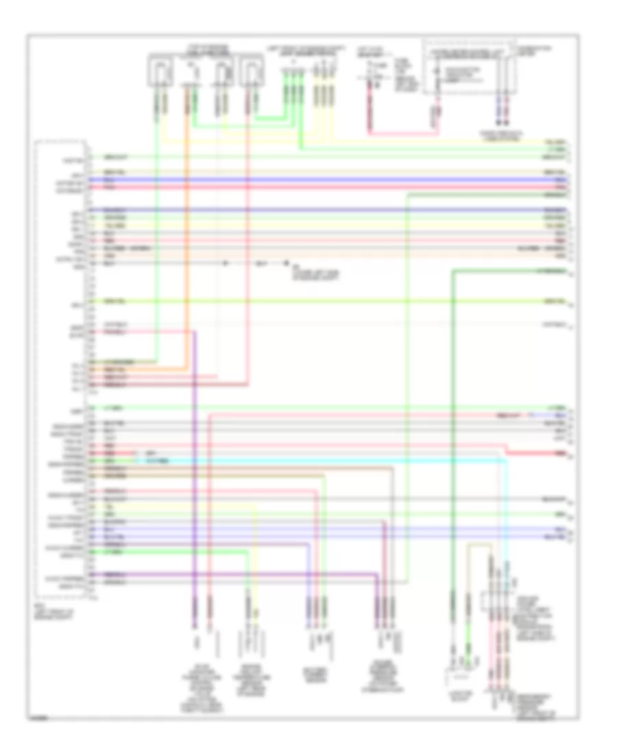
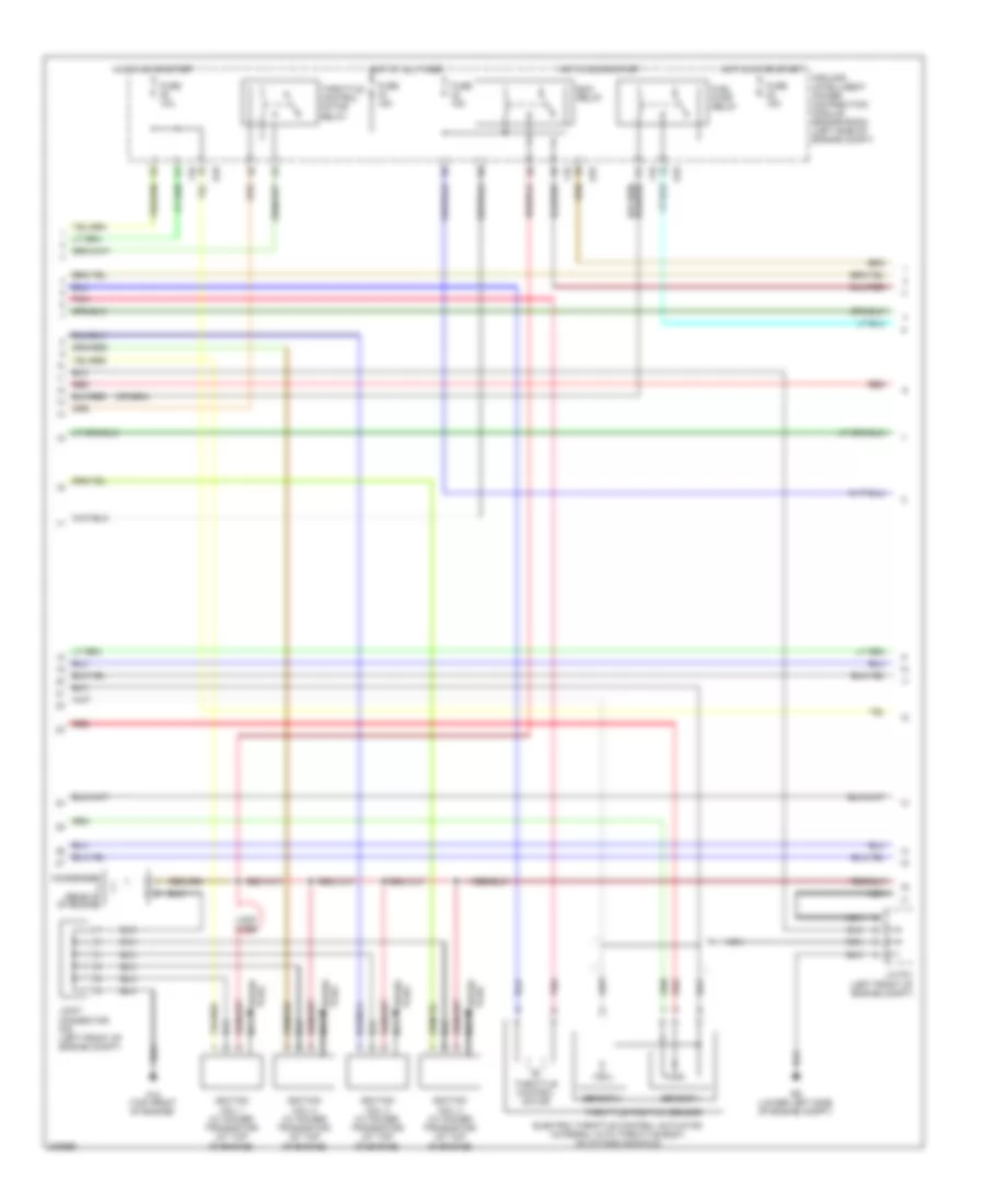
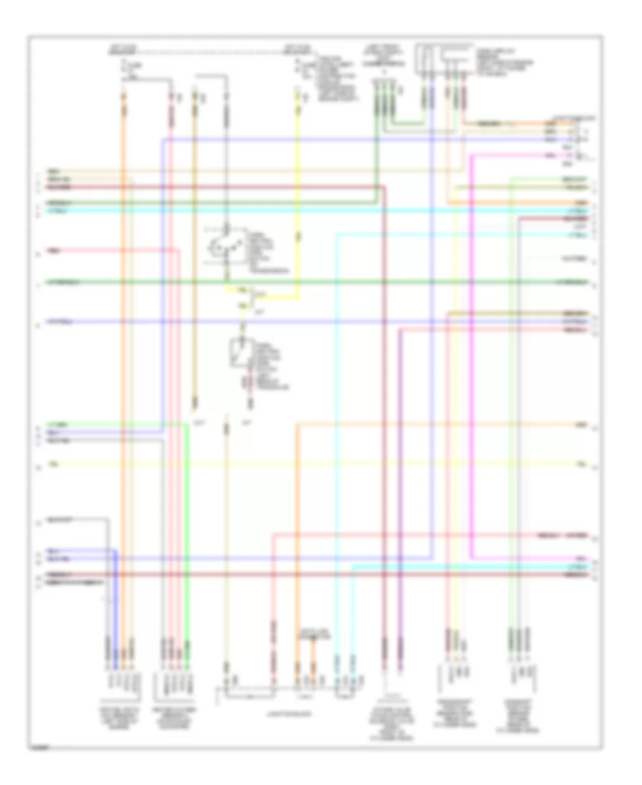
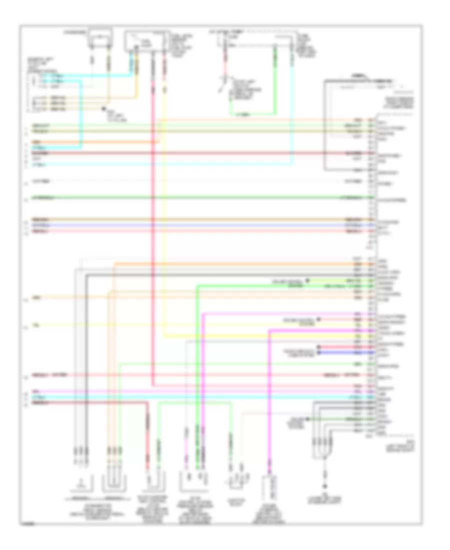
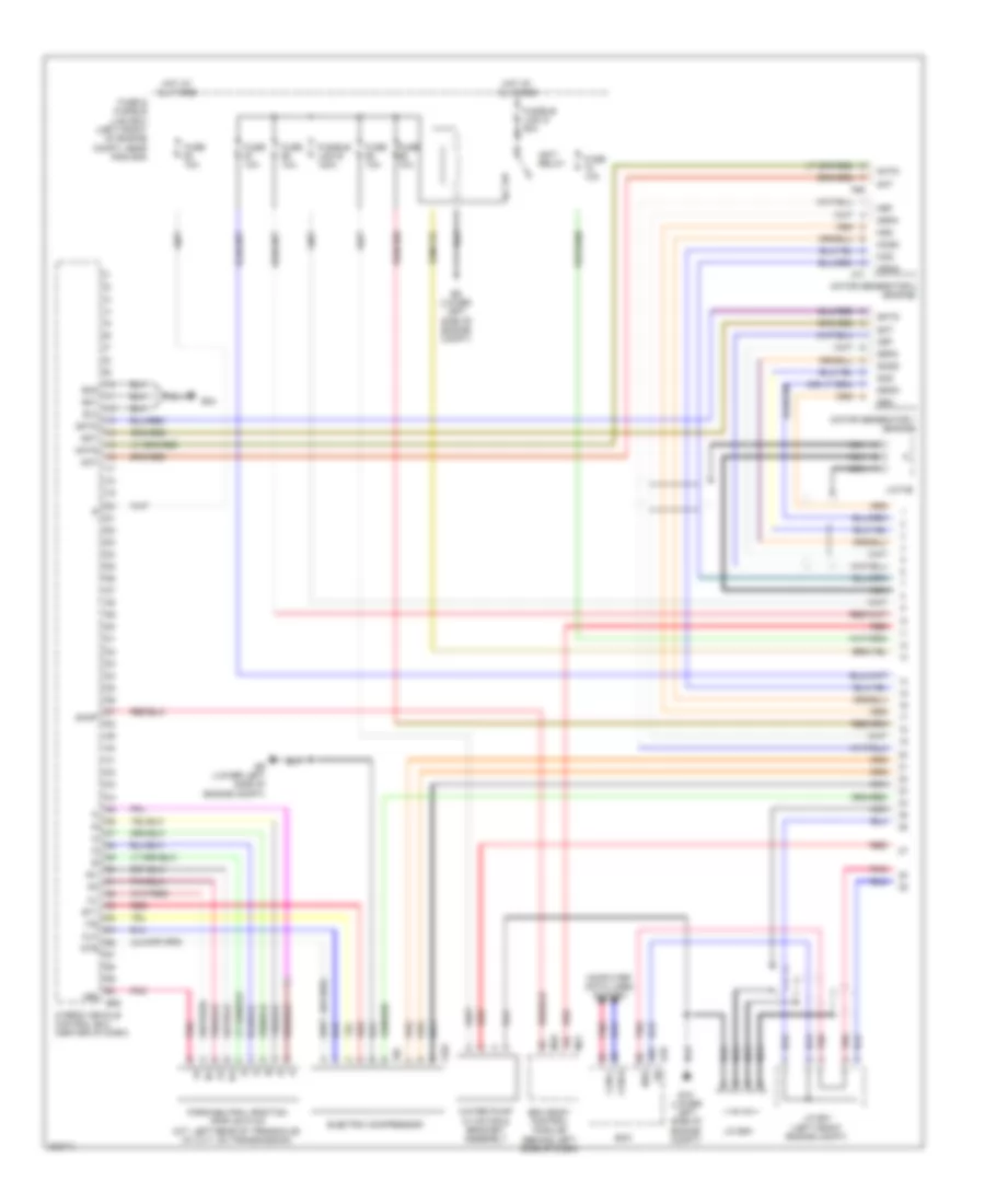
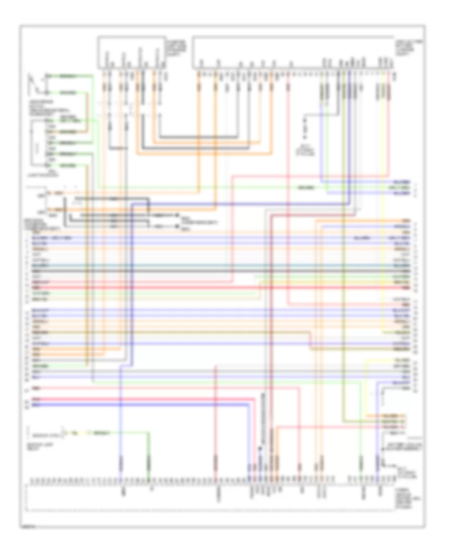
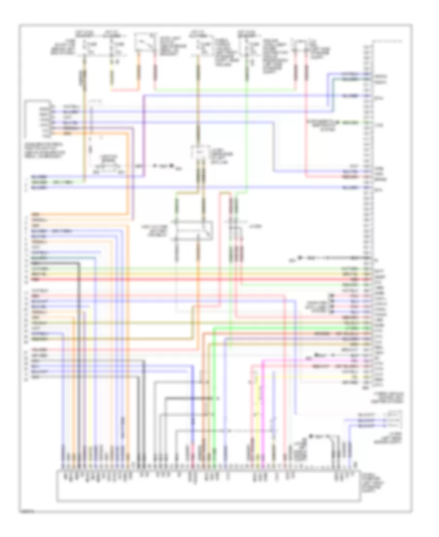
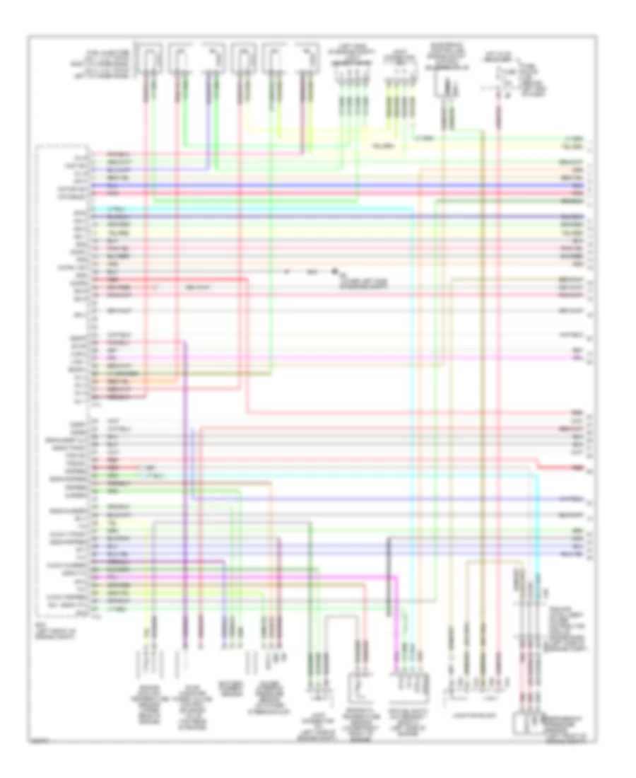
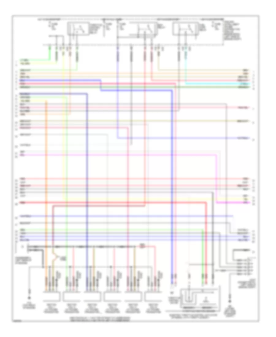
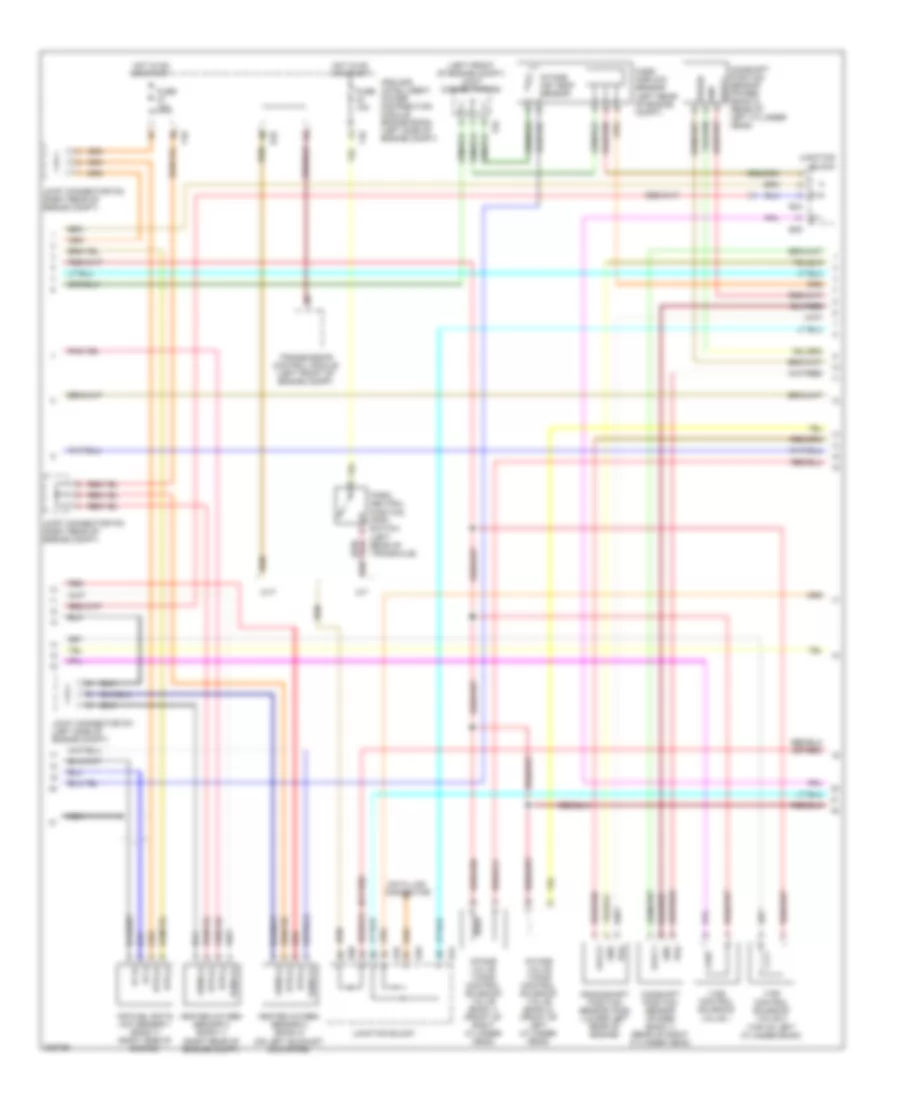
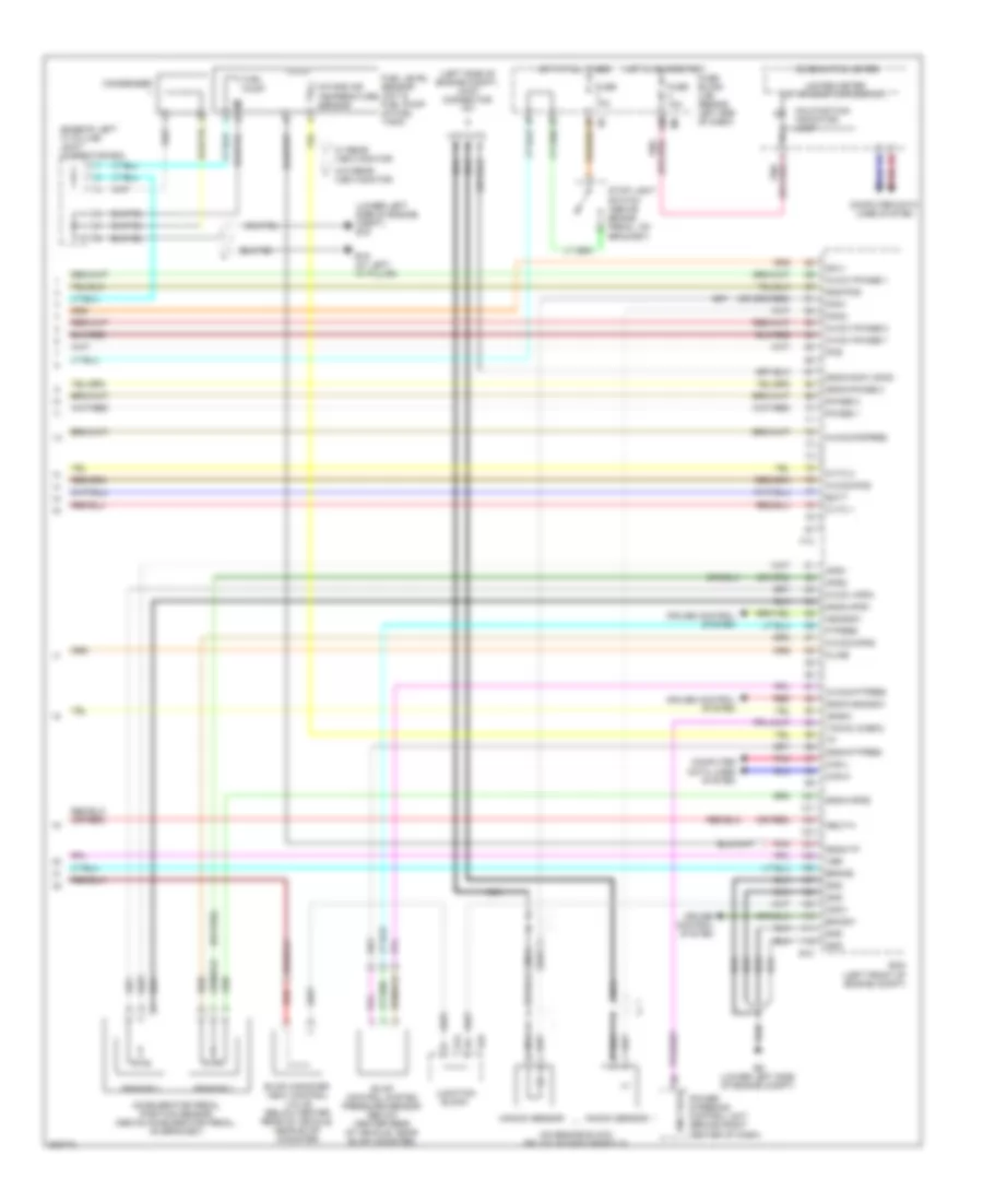
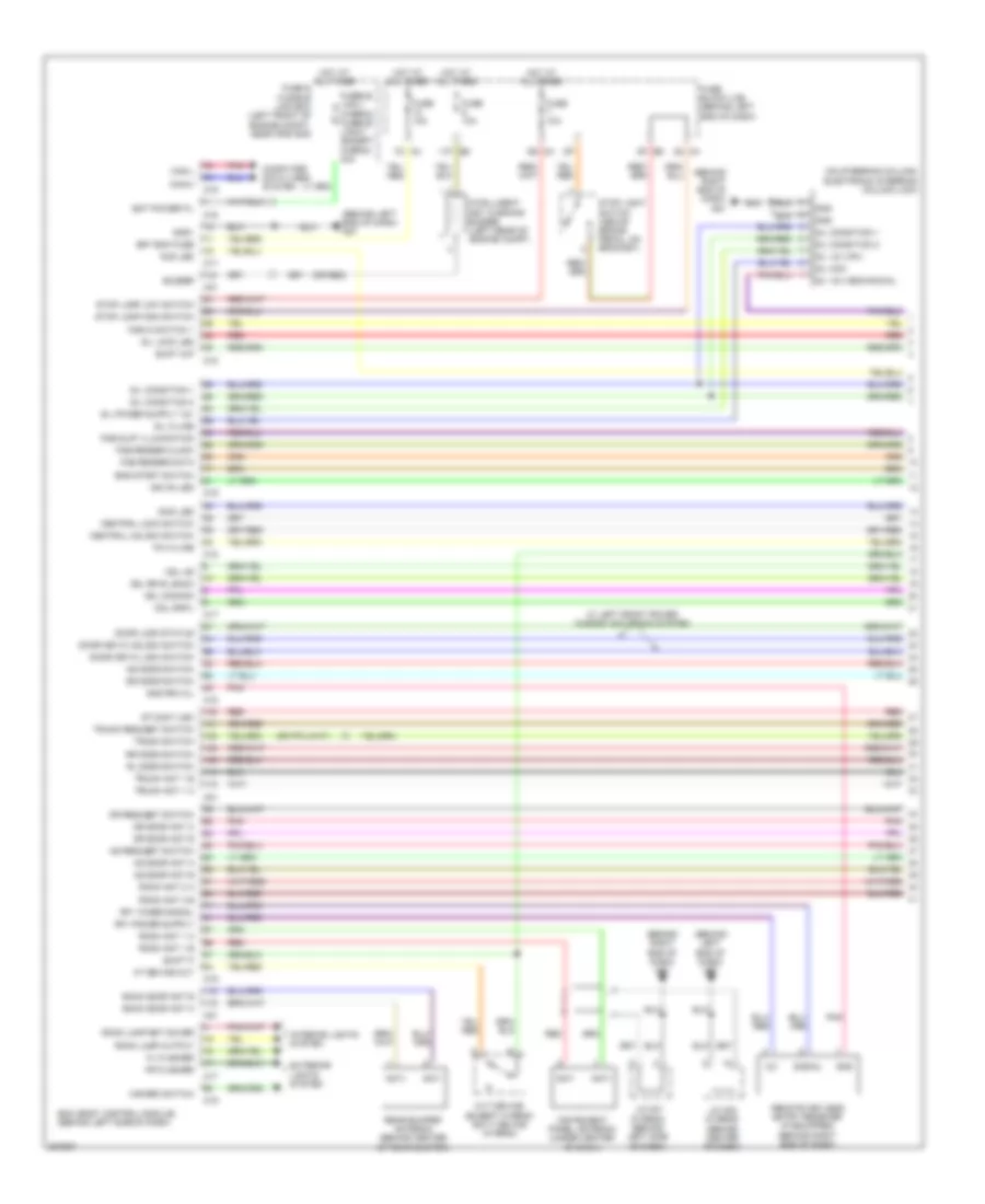
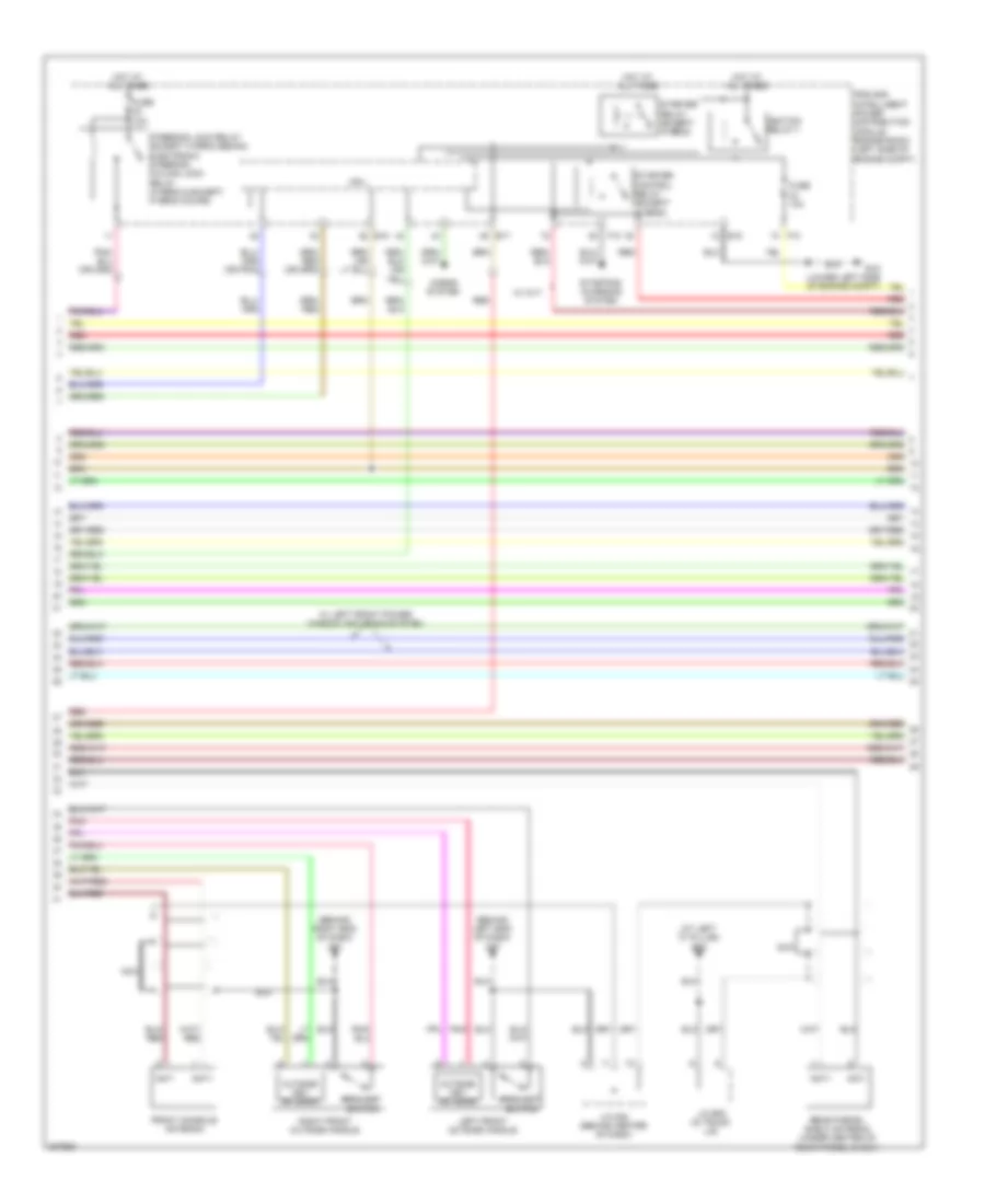
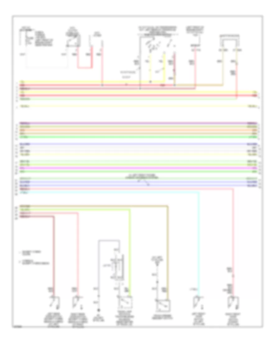
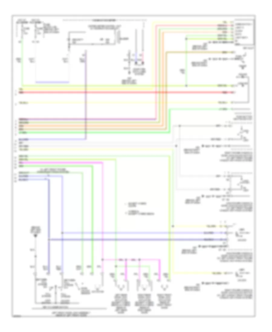
AIR CONDITIONING Automatic A/C Wiring Diagram, Except Hybrid (1 of 2) for Nissan Altima SE 2009 List of elements for Automatic A/C Wiring Diagram, Except Hybrid (1 of 2) for Nissan Altima SE 2009: 73 (behind right end of dash) m61 2n m3 3n m3 5n m3 6p e6 6q m4 7m m5 A/c pd cut Acc Aircon sw Amb sens Amb vdd Ambient sensor (behind lower left side of front grille) Batt Blower motor (behind lower right side of dash) Body control module (bcm) (behind left side of dash) Bwr fan sw Can-h Can-l Combination meter Comp on Defogger system E18 E201 Fan on Fan pwm Front air control Front blower motor relay Fuse & fusible link box (left front of engine compt, near ipdm e/r) Fuse 10a Fuse 15a Fuse block (j/b) (behind left end of dash) Fusible link k 40a Fusible link m 40a Gnd Gnd (oat sens) Gnd (pwr) Hot at all times Hot in on or acc Hot in on or start Ign Ign 2 Ign2 cont Ill+ Ill- In-vehicle sensor (left center of dash, near ignition switch) Inc sens Int sens Intake door motor Intake sensor (behind right side of dash, on hvac assembly) Interior lights system Ipdm e/r (intelligent power distribution module engine room) (left side of engine compt) J/c e01 Lan sig Left air mix door motor M18 M19 M57 (behind left end of dash) M61 (behind right end of dash) Mode door motor Oat Oat pwr Pd cut Pnk Right air mix door motor Rr def f/b Rr def on Sens gnd Sun sens Sunload sensor (upper left side of dash, near base of windshield) Vactr Water temp Water temp out Automatic A/C Wiring Diagram, Except Hybrid (2 of 2) for Nissan Altima SE 2009 List of elements for Automatic A/C Wiring Diagram, Except Hybrid (2 of 2) for Nissan Altima SE 2009: 60 & 3.5l (left side of engine compt) e204 (lower left side of engine compt) e9 (or red) (right front of engine compt) cooling fan motor 2 2.5l california 2.5l california & 3.5l 2.5l except california 3.5l A/c compressor (at lower left front of engine) A/c relay Avcc-pdpres Avcc2 Can-h Can-l Computer data lines system Cooling fan motor 1 (left front of engine compt) Cooling fan relay 1 Cooling fan relay 2 Cooling fan relay 3 Cpu E10 E15 (lower left side of engine compt) E17 E18 E201 E44 E45 E47 E48 Ecm (left front of engine compt) Engine coolant temperature sensor (2.5l: left rear of engine) (3.5l: upper rear of engine) F10 F13 Fuse 10a Fuse 15a Gnd Gnda-pdres Gnda-tw Hot at all times Hot in on or start Ig+ Ignition relay 1 Ipdm e/r (intelligent power distribution module engine room) (left side of engine compt) J/c e02 J/c e03 (left rear of engine compt) J/c e04 (left side of engine compt) J/c f01 (3.5l) j/c f06 (2.5l california) (3.5l: left side of engine compt) (2.5l california: left front of engine compt) J/c f07 (left side of engine compt) Junction block e44 & e45 Junction block e44, e47 & e48 Mtr fan rly hi Mtr fan rly mid P-gnd Pdres Pnk Red Refrigerant pressure sensor (left front of engine compt) S-gnd Sig Automatic A/C Wiring Diagram, Hybrid (1 of 2) for Nissan Altima SE 2009 List of elements for Automatic A/C Wiring Diagram, Hybrid (1 of 2) for Nissan Altima SE 2009: 89 (behind right end of dash) m61 (lower left side of engine compt) e9 2n m3 3n m3 4p e6 5n m3 6p e6 6q m4 7m m5 Acc Aircon sw Amb sens Amb vdd Ambient sensor (behind lower left side of front grille) Amp Batt Blower motor (behind lower right side of dash) Body control module (bcm) (behind left side of dash) Bwr fan sw Can-h Can-l Clk Combination meter Comp on Controller (auto amp) Defogger system Din Dout E18 E201 E44 E46 Electric compressor Et1 F250 F252 F85 Fan on Fan pwm Front blower motor relay Fuse 10a Fuse 15a Fuse block (j/b) (behind left end of dash) Gnd Gnd (oat pwr) Gnd (pwr) Hot at all times Hot in on or acc Hot in on or start Hybrid vehicle control ecu (center of dash) Ign Ign2 cont Ill+ Ill- In-vehicle sensor (left center of dash, near ignition switch) Inc sens Int sens Intake door motor Intake sensor (behind right side of dash, on hvac assembly) Interior lights system Inverter (left side of engine compt) Ipdm e/r (intelligent power distribution module engine room) (left side of engine compt) Ite Junction block e44 & e46 Lan sig Left air mix door motor M18 M19 M57 (behind left end of dash) M61 (behind right end of dash) Mode door motor Nca Oat Oat pwr Pbat Pgnd Pnk Red Right air mix door motor Rr def f/b Rr def on Sens gnd Sh pbat Sh pgnd Stb Stb1 Sun sens Sunload sensor (upper left side of dash, near base of windshield) Vactr Automatic A/C Wiring Diagram, Hybrid (2 of 2) for Nissan Altima SE 2009 List of elements for Automatic A/C Wiring Diagram, Hybrid (2 of 2) for Nissan Altima SE 2009: 54 (left side of engine compt) e204 (or red) Avcc-pdpres Avcc2 Can-h Can-l Computer data lines system Cooling fan control module (front of engine compt) Cooling fan motor 1 (left front of engine compt) Cooling fan motor 2 (right front of engine compt) Cooling fan relay-1 (left rear engine compt) Cpu E10 E15 (lower left side of engine compt) E17 E18 E201 E231 E232 E233 E47 E48 E9 (lower left side of engine compt) Ecm Engine coolant temperature sensor (left rear of engine) F10 F13 Fuse & fusible link box (left front of engine compt, near ipdm e/r) Fuse 10a Fuse 15a Fusible link o 50a Gnd Gnda-pdres Gnda-tw Heater pump Heater pump relay Hot at all times Hot in on or start Ig+ Ignition relay 1 Ipdm e/r (intelligent power distribution module engine room) (left side of engine compt) J/c e07 (at right side of dash) Junction block e47 & e48 Motor fan pwm Motor fan rly mid P-gnd Pdres Pnk Pwm pwr Pwm sig Red Refrigerant pressure sensor (left front of engine compt) S-gnd Sig Manual A/C Wiring Diagram, Except Hybrid (1 of 2) for Nissan Altima SE 2009 List of elements for Manual A/C Wiring Diagram, Except Hybrid (1 of 2) for Nissan Altima SE 2009: 51 (behind right end of dash) m61 6p e6 6q m4 7m m5 A/c pd cut Air mix door motor Aircon sw Batt Blower motor (behind lower right side of dash) Body control module (bcm) (behind left side of dash) Bwr fan sw Can-h Can-l Combination meter Comp on Defogger system Fan on Fan pwm Front air control Front blower motor relay Fuse & fusible link box (left front of engine compt, near ipdm e/r) Fuse 10a Fuse 15a Fuse block (j/b) (behind left end of dash) Fusible link k 40a Fusible link m 40a Gnd Gnd (pwr) Hot at all times Hot in on or start Ign Ign 2 Ign2-cont Ill+ Ill- Intake door motor Interior lights system J/c e01 Lan sig M18 M19 can-h M3 2n M3 3n M57 (behind left end of dash) M61 (behind right end of dash) Mode door motor Pd cut Pnk Rr def f/b Rr def on Vactr Manual A/C Wiring Diagram, Except Hybrid (2 of 2) for Nissan Altima SE 2009 List of elements for Manual A/C Wiring Diagram, Except Hybrid (2 of 2) for Nissan Altima SE 2009: 60 (left side of engine compt) e204 (lower left side of engine compt) e9 (or red) (right front of engine compt) cooling fan motor 2 2.5l california 2.5l california & 3.5l 2.5l except california 2.5l except california & 3.5l 3.5l A/c compressor (at lower left front of engine) A/c relay Avcc-pdpres Avcc2 Can-h Can-l Computer data lines system Cooling fan motor 1 (left front of engine compt) Cooling fan relay 1 Cooling fan relay 2 Cooling fan relay 3 Cpu E10 E15 (lower left side of engine compt) E17 E18 E201 E44 E45 E47 E48 Ecm (left front of engine compt) Engine coolant temperature sensor (2.5l: left rear of engine) (3.5l: upper rear of engine) F10 F13 Fuse 10a Fuse 15a Gnd Gnda-pdres Gnda-tw Hot at all times Hot in on or start Ig+ Ignition relay 1 Ipdm e/r (intelligent power distribution module engine room) (left side of engine compt) J/c e02 J/c e03 (left rear of engine compt) J/c e04 (left side of engine compt) J/c f01 (3.5l) j/c f06 (2.5l california) (3.5l: left side of engine compt) (2.5l california: left front of engine compt) J/c f07 (left side of engine compt) Junction block e44 & e45 Junction block e44, e47 & e48 Mtr fan rly hi Mtr fan rly mid P-gnd Pdres Pnk Red Refrigerant pressure sensor (left front of engine compt) S-gnd Sig
ANTI-LOCK BRAKES Anti-lock Brakes Wiring Diagram, Except Hybrid with Traction Control with Stability Assist for Nissan Altima SE 2009 List of elements for Anti-lock Brakes Wiring Diagram, Except Hybrid with Traction Control with Stability Assist for Nissan Altima SE 2009: 81 (at base of parking brake lever) parking brake switch (behind left end of dash) m57 (behind right end of dash) m61 12m m5 Abs actuator & electric unit (control unit) (right rear of engine compt) Abs control unit Abs ind Actuator Asr aus Bls Brake fluid level switch (on master cylinder fluid reservoir) Brake ind Can-h Can-l Can-m2 Can-p2 Combination meter Computer data lines system Diag-k Dp fl Dp fr Dp rl Dp rr Ds fl Ds fr Ds rl Ds rr E10 E15 (lower left side of engine compt) E18 E33 E44 E46 E47 E49 E6 8p Ecm (left front of engine compt) Fl in Fl out Fr in Fr out Fuse & fusible link box (left front of engine compt, near ipdm e/r) Fuse 10a Fuse block (j/b) (behind left end of dash) Fusible link f 50a Fusible link g 30a Gnd Hot at all times Hot in on or start Hsv 1 Hsv 2 Interior lights system Ipdm e/r (intelligent power distribution module engine room) (left side of engine compt) J/c e03 (left rear of engine compt) J/c e04 (left side of engine compt) J/c m01 (behind left side of dash) J/c m02 (behind center of dash) Junction block Left front wheel sensor (at left front wheel hub assembly) M57 (behind left end of dash) Motor Motor relay Pnk Rear wheel sensor (under rear of vehicle) Red Relay unit Right front wheel sensor (at right front wheel hub assembly) Rl in Rl out Rr in Rr out Slip ind Solenoid valve relay Steering angle sensor (on steering column) Stop light switch (above brake pedal, on bracket) Unified meter control unit Vdc off ind Vds off switch Vsv 1 Vsv 2 Yaw rate/ side/decel g sensor (under rear of center console) Anti-lock Brakes Wiring Diagram, Except Hybrid with Traction Control without Stability Assist for Nissan Altima SE 2009 List of elements for Anti-lock Brakes Wiring Diagram, Except Hybrid with Traction Control without Stability Assist for Nissan Altima SE 2009: 67 (behind left end of dash) m57 (behind right end of dash) m61 (or red) 8p e6 Abs actuator & electric unit (control unit) (right rear of engine compt) Abs control unit Abs ind Actuator Bls Can-h Can-l Combination meter Computer data lines system Data link connector Diag-k Dp fl Dp fr Dp rl Dp rr Ds fl Ds fr Ds rl Ds rr E10 E18 E33 E44 E46 Ecm (left front of engine compt) Fl in Fl out Fr in Fr out Fuse & fusible link box (left front of engine compt, near ipdm e/r) Fuse 10a Fuse block (j/b) (behind left end of dash) Fusible link g 30a Fusible link i 40a Gnd Hot at all times Hot in on or start Ign Interior lights system Ipdm e/r (intelligent power distribution module engine room) (left side of engine compt) J/c e03 (left rear of engine compt) J/c e04 (left side of engine compt) J/c m01 (behind left of dash) Junction block Left front wheel sensor (at left front wheel hub assembly) M5 12m Motor Motor relay Pnk Rear wheel sensor (under rear of vehicle) Red Relay unit Right front wheel sensor (at right front wheel hub assembly) Rl in Rl out Rr in Rr out Slip ind Solenoid valve relay Stop light switch (above brake pedal, on bracket) Tcs off ind Tcs off switch Unified meter control unit (w/ information display) Anti-lock Brakes Wiring Diagram, Except Hybrid without Traction Control for Nissan Altima SE 2009 List of elements for Anti-lock Brakes Wiring Diagram, Except Hybrid without Traction Control for Nissan Altima SE 2009: 61 (behind left end of dash) m57 (or red) (w/ information display) unified meter control unit 12m m5 8p e6 Abs actuator & electric unit (control unit) (right rear of engine compt) Abs control unit Abs ind Actuator Bls Can-h Can-l Combination meter Computer data lines system Data link connector Diag-k Dp fl Dp fr Dp rl Dp rr Ds fl Ds fr Ds rl Ds rr E10 E18 E33 E44 E46 Ecm (left front of engine compt) Fl in Fl out Fr in Fr out Fuse & fusible link box (left front of engine compt, near ipdm e/r) Fuse 10a Fuse block (j/b) (behind left end of dash) Fusible link g 30a Fusible link i 40a Gnd Hot at all times Hot in on or start Ign Ipdm e/r (intelligent power distribution module engine room) (left side of engine compt) J/c e03 (left rear of engine compt) J/c e04 (left side of engine compt) Junction block Left front wheel sensor (at left front wheel hub assembly) Motor Motor relay Pnk Rear wheel sensor (under rear of vehicle) Red Relay unit Right front wheel sensor (at right front wheel hub assembly) Rl in Rl out Rr in Rr out Solenoid valve relay Stop light switch (above brake pedal, on bracket) Anti-lock Brakes Wiring Diagram, Hybrid (1 of 3) for Nissan Altima SE 2009 List of elements for Anti-lock Brakes Wiring Diagram, Hybrid (1 of 3) for Nissan Altima SE 2009: 80 (right rear engine compt) abs motor relay 1 (right rear engine compt) abs relay 1 B+cty B2o Brake ecu (right rear of engine compt) Brake simulator (left rear engine compt) Brake stroke sensor (at brake pedal assembly) Brake warning buzzer (center of dash) Bs1 Bso1 Bso3 Bz (sig) Bzo (pwr) Can-h Can-l Cbi1 Cin Computer data lines system Cout Di1 Do1 E15 (lower left side of engine compt) E18 E24 E44 E45 E46 E47 E50 E60 E62 E66 Fr+ Fr- Fra+ Fra- Frr+ Frr- Fuse & fusible link box (left front of engine compt, near ipdm e/r) Fuse 10a Fuse 15a Fusible link i 30a Gnd Hot at all times Hot in on or start Hybrid vehicle control ecu (center of dash) Ig1 Ipdm e/r (intelligent power distribution module engine room) (left side of engine compt) Junction block M61 (behind right end of dash) Mr1 Mtt Pac1 Pck1 Pfr Pmc1 Pnk Prl R1+ R1- R3+ Red Right front wheel sensor (at right front wheel hub assembly) Rl+ Rl- Rla+ Rla- Rlr+ Rlr- Skg Sks Sks2 Smc1 Sp1 Spd1 Steering angle sensor (on steering column) Stp Vcm1 Vcsk Yaw rate/side/decel g sensor Anti-lock Brakes Wiring Diagram, Hybrid (2 of 3) for Nissan Altima SE 2009 List of elements for Anti-lock Brakes Wiring Diagram, Hybrid (2 of 3) for Nissan Altima SE 2009: 18 (in left "b" pillar) left front door switch +bcty B117 (at right "c" pillar) Brake actuator (right rear engine compt) Brake capacitor (right luggage compt) Cty E24 E44 E45 E46 Ena Fail Gnd Junction block Motor Out Out2 Red Anti-lock Brakes Wiring Diagram, Hybrid (3 of 3) for Nissan Altima SE 2009 List of elements for Anti-lock Brakes Wiring Diagram, Hybrid (3 of 3) for Nissan Altima SE 2009: 65 (right rear engine compt) abs relay 2 12m Abs ind Abs motor relay 2 (right rear engine compt) Brake ecu (right rear of engine compt) Brake fluid level switch (on master cylinder fluid reservoir) Brake ind Bs02 Bs2 Can-h Can-l Cb12 Combination meter Computer data lines system D12 Do2 E15 (lower left side of engine compt) E47 E49 E61 Electronically control brake ind Fl+ Fl- Fla+ Fla- Flr+ Flr- Fuse & fusible link box (left front of engine compt, near ipdm e/r) Fuse 10a Fuse block (j/b) (behind left end of dash) Fusible link h 50a Gnd Hot at all times Hot in on or start Ig2 J/c e04 (left side of engine compt) Junction block Lbl Left front wheel sensor (at left front wheel hub assembly) M57 (behind left end of dash) Mr2 Parking brake switch (at base of parking brake lever) Pck2 Pfl Pkb Pmc2 Pnk Prr R2+ R2- R4+ Rear wheel sensor (under rear of vehicle) Red Rr+ Rr- Rra+ Rra- Rrr+ Rrr- Slip ind Smc2 Stop light switch (above brake pedal, on bracket) Unified meter control unit (w/ information display) Vdc ind Vmc2
ANTI-THEFT Anti-theft Wiring Diagram, with Intelligent Key Unit (2 of 4) for Nissan Altima SE 2009 List of elements for Anti-theft Wiring Diagram, with Intelligent Key Unit (2 of 4) for Nissan Altima SE 2009: 32 (at left "c" pillar) b19 (behind left end of dash) m57 (behind right end of dash) m61 Ant+ Ant- Cpu E15 (lower left side of engine compt) E17 E18 F10 Front console antenna Fuse 10a Horns system Hot at all times Ignition relay-1 Ipdm e/r (intelligent power distribution module engine room) (left side of engine compt) J/c b05 (in trunk lid) J/c m02 (behind center of dash) Left front outside handle Nca Outside key antenna Pnk Rear parcel shelf antenna (under center of rear parcel shelf) Red Request switch Right front outside handle Starter control relay (except hybrid) Starter relay (except hybrid) Starting/ charging system Steering lock relay (except hybrid sedan) electronic steering column lock relay (hybrid & except hybrid coupe) W/ cvt W/ left front power window anti-pinch system Anti-theft Wiring Diagram, with Intelligent Key Unit (3 of 4) for Nissan Altima SE 2009 List of elements for Anti-theft Wiring Diagram, with Intelligent Key Unit (3 of 4) for Nissan Altima SE 2009: 28 (at left "c" pillar) b19 (left front of engine compt) (w/ cvt & 3.5l) tcm (m/t) clutch interlock switch (m/t) j/c e05 (w/ cvt & 2.5l: on transmission) (m/t: left rear of transaxle) park/neutral position (pnp) switch B7 (on left "b" pillar) E46 E50 Except hybrid coupe F16 Fuse & fusible link box (left front of engine compt, near ipdm e/r) Fuse 10a Hot at all times Hybrid & except hybrid sedan J/c t01 Junction block Left front door switch (in left "b" pillar) Left rear door switch (except hybrid sedan & hybrid) (at left "c" pillar) M/t Red Right front door switch (in right "b" pillar) Right rear door switch (except hybrid sedan & hybrid) (at right "c" pillar) St rly Trunk lamp switch & trunk release solenoid (rear center of trunk lid) Trunk opener request switch W/ cvt W/ cvt & 2.5l W/ left front power window anti-pinch system Anti-theft Wiring Diagram, with Intelligent Key Unit (4 of 4) for Nissan Altima SE 2009 List of elements for Anti-theft Wiring Diagram, with Intelligent Key Unit (4 of 4) for Nissan Altima SE 2009: 49 (behind left end of dash) m57 1n m3 Acc ind Actuator Between full stroke & n Buzzer Care switch 1 Clock Combination meter Computer data lines system Cpu Data Door unlock sensor Except hybrid coupe Full stroke Fuse 10a Fuse block (j/b) (behind left end of dash) Gnd Hot at all times Hybrid & except hybrid sedan Key cylinder switch Key ind Key slot Left front door lock assembly (rear of left front door) Left rear door lock actuator (except hybrid sedan & hybrid) (rear of left rear door) Light a Light bat+ Lock Lock ind Lock switch M57 (behind left end of dash) M61 (behind right end of dash) Main power window & door lock/unlock switch (w/ left & right front power window anti-pinch system) Main power window & door lock/unlock switch (w/ left front power window anti-pinch system) On ind Pnk Push button ignition switch Push switch Red Right front door lock actuator (rear of right front door) Right power window & door lock/unlock switch (w/ left & right front power window anti-pinch system) Right power window & door lock/unlock switch (w/ left front power window anti-pinch system) Right rear door lock actuator (except hybrid sedan & hybrid) (rear of right rear door) Security ind Un lock Unified meter control unit (w/ information display) Unlock Unlock switch W/ left front power window anti-pinch system Anti-theft Wiring Diagram, without Intelligent Key Unit (1 of 3) for Nissan Altima SE 2009 List of elements for Anti-theft Wiring Diagram, without Intelligent Key Unit (1 of 3) for Nissan Altima SE 2009: 92 (behind left end of dash) m57 (behind right end of dash) m61 (on steering column) electronic steering column lock 12v 2p e6 7n m3 Acd led Ant+ Ant- As door switch At device out Bat bcm fuse Bat power f/l Bcm (body control module) (behind left side of dash) Buzzer Can-h Can-l Cdl as Cdl common Cdl dr/fl Cdl rr rl back Central lock switch Central unlock switch Computer data lines system Cvt device (if equipped) Door key/c lock switch Door key/c unlock switch Door lock status Dr door switch E6 11p Eng start switch Exterior lights system Fl flasher Fob in switch 1 Fob reader clock Fob reader data Fob slot illumination Fr flasher Fuse & fusible link box (left front of engine compt, near ipdm e/r) Fuse 10a Fuse block (j/b) (behind left end of dash) Fusible link j (hybrid) fusible link h (except hybrid) 40a Gnd Gnd rf2 a/l Gnd1 Hazard switch Hot at all times Ign on led Immo led Instrument panel antenna (under center of dash) Interior lights system Left rear door switch (except hybrid sedan & hybrid) (at left "c" pillar) M16 M17 M18 M19 M21 M4 3q M4 9q Outside warning buzzer Pnk Pw k-line Red Remote keyless entry receiver (if equipped) (behind right end of dash) Rf1 tuner signal Right rear door switch (except hybrid sedan & hybrid) (at right "c" pillar) Rl door switch Room ant 1 a Room ant 1 b Room ant 2 a Room ant 2 b Room lamp bat saver Room lamp output Rr door switch S/l 12v cpu S/l 12v mechanical S/l com S/l condition 1 S/l condition 2 S/l k-line S/l lock led Shift n/p Shift p Signal St cont usm Stop lamp high switch Stop lamp low switch Stop light switch (above brake pedal, on bracket) Trunk ant 1 a Trunk ant 1 b Trunk switch W/ left front power window anti-pinch system Anti-theft Wiring Diagram, without Intelligent Key Unit (2 of 3) for Nissan Altima SE 2009 List of elements for Anti-theft Wiring Diagram, without Intelligent Key Unit (2 of 3) for Nissan Altima SE 2009: 31 Ant+ Ant- B7 (on left "b" pillar) Cpu E15 (lower left side of engine compt) E17 E18 E46 E50 Except hybrid coupe F10 Front console antenna Fuse 10a Horns system Hot at all times Hybrid & except hybrid sedan Ignition relay-1 Ipdm e/r (intelligent power distribution module engine room) (left side of engine compt) J/c t01 Junction block Left front door switch (in left "b" pillar) Park/neutral position (pnp) switch (w/ cvt & 2.5l: on transmission) (m/t: left rear of transaxle) Rear parcel shelf antenna (under center of rear parcel shelf) Red Right front door switch (in right "b" pillar) Starter control relay (except hybrid) Starter relay (except hybrid) Starting/ charging system Steering lock relay Trunk light switch & trunk release solenoid (rear center of trunk lid) W/ left front power window anti-pinch system Anti-theft Wiring Diagram, without Intelligent Key Unit (3 of 3) for Nissan Altima SE 2009 List of elements for Anti-theft Wiring Diagram, without Intelligent Key Unit (3 of 3) for Nissan Altima SE 2009: 51 (behind left end of dash) m57 1n m3 Acc ind Actuator Between full stroke & n Buzzer Care switch 1 Clock Combination meter Computer data lines system Cpu Data Door unlock sensor Except hybrid Except hybrid coupe Full stroke Fuse 10a Fuse block (j/b) (behind left end of dash) Gnd Hot at all times Hybrid Key cylinder switch Key ind Key slot Left front door lock assembly (rear of left front door) Left rear door lock actuator (except hybrid sedan & hybrid) (rear of left rear door) Light a Light bat+ Lock Lock ind Lock switch M57 (behind left end of dash) M61 (behind right end of dash) Main power window & door lock/unlock switch (w/ left & right front power window anti-pinch system) Main power window & door lock/unlock switch (w/ left front power window anti-pinch system) On ind Pnk Push button ignition switch Push switch Red Right front door lock actuator (rear of right front door) Right power window & door lock/unlock switch (w/ left & right front power window anti-pinch system) Right power window & door lock/unlock switch (w/ left front power window anti-pinch system) Right rear door lock actuator (except hybrid sedan & hybrid) (rear of right rear door) Security ind Sedan & hybrid Un lock Unified meter control unit (w/ information display) Unlock Unlock switch W/ left front power window anti-pinch system
BODY CONTROL MODULES
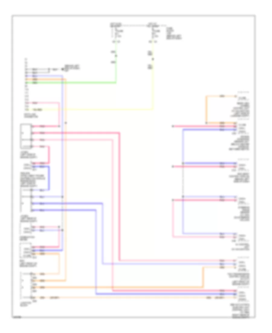
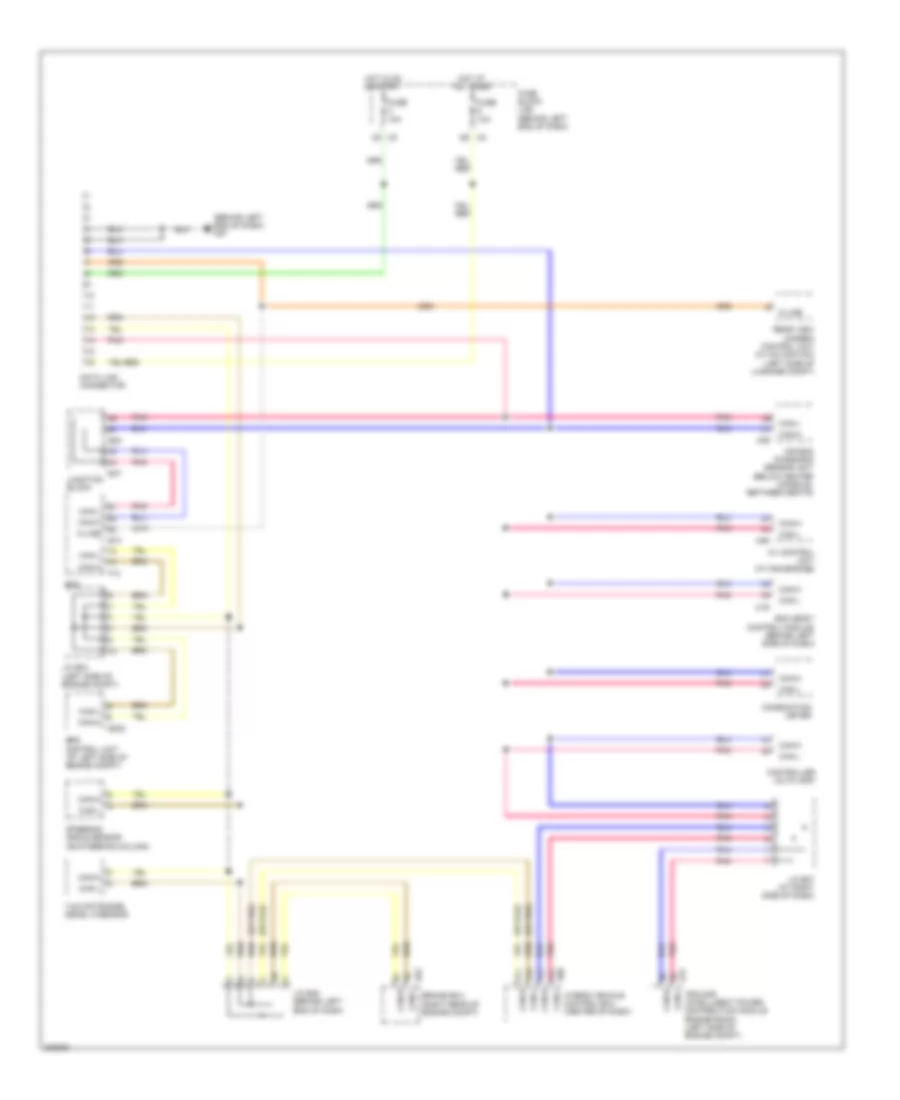
COMPUTER DATA LINES Computer Data Lines Wiring Diagram, Except Hybrid for Nissan Altima SE 2009 List of elements for Computer Data Lines Wiring Diagram, Except Hybrid for Nissan Altima SE 2009: 33 (behind left end of dash) (behind left end of dash) m57 Abs actuator & electric unit (control unit) (w/ abs) (right rear of engine compt) Air bag diagnosis sensor unit (below center console, between seats) Av control unit (w/ navigation) Bcm (body control module) (behind left side of dash) Can-h Can-l Combination meter Data link connector Diag-k E10 E17 E45 E46 E50 Ecm (left front of engine compt) Fuse 10a Fuse block (j/b) Hot at all times Hot in on or start Ipdm e/r (intelligent power distribution module engine room) (left side of engine compt) J/c e03 (left rear of engine compt) J/c e04 (left side of engine compt) Junction block K-line M19 M35 M46 Pnk Rear view camera control unit (w/ navigation) (left side of luggage compt) Steering angle sensor (w/ vdc) (on steering column) Tcm (transmission control module) (w/ cvt) (left front of engine compt) Computer Data Lines Wiring Diagram, Hybrid for Nissan Altima SE 2009 List of elements for Computer Data Lines Wiring Diagram, Hybrid for Nissan Altima SE 2009: 40 (behind left end of dash) (behind left end of dash) m57 (or pnk) Air bag diagnosis sensor unit (below center console, between seats) Av control unit (w/ navigation) Bcm (body control module) (behind left side of dash) Brake ecu (right rear of engine compt) Can-h Can-l Combination meter Controller (auto amp) Data link connector E10 E17 E302 E47 E48 E61 E66 Ecm Eps control unit (at left side of engine compt) F13 Fuse 10a Fuse block (j/b) Hot at all times Hot in on or start Hybrid vehicle control ecu (center of dash) Ipdm e/r (intelligent power distribution module engine room) (left side of engine compt) J/c e04 (left side of engine compt) J/c e06 (behind left end of dash) J/c e07 (at right side of dash) Junction block K-line M19 M35 M46 Pnk Rear view camera control unit (w/ navigation) (left side of luggage compt) Steering angle sensor (on steering column) Yaw rate/side/ decel g sensor
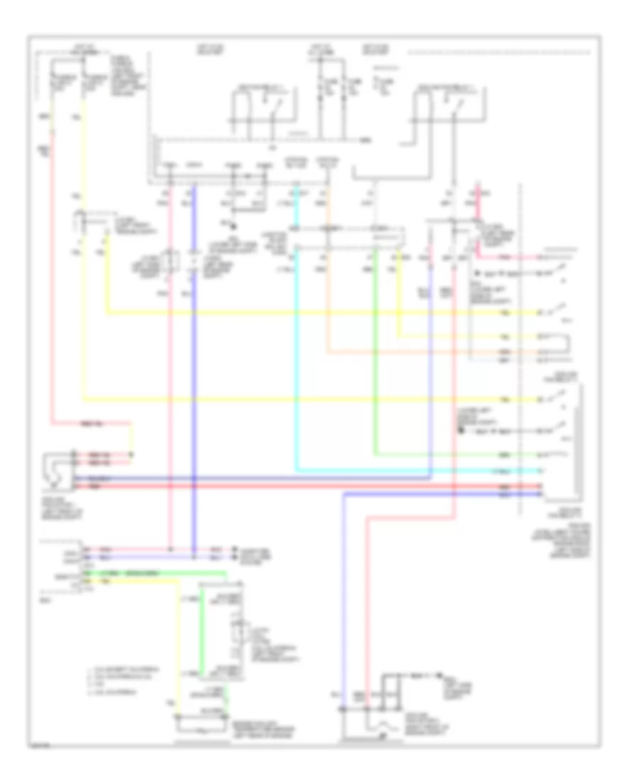
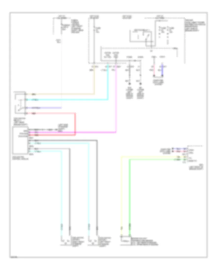
COOLING FAN Cooling Fan Wiring Diagram, Except Hybrid for Nissan Altima SE 2009 List of elements for Cooling Fan Wiring Diagram, Except Hybrid for Nissan Altima SE 2009: 48 (lower left side of engine compt) e9 2.5l california 2.5l california & 3.5l 2.5l except california 3.5l Can-h Can-l Computer data lines system Cooling fan motor 1 (left front of engine compt) Cooling fan motor 2 (right front of engine compt) Cooling fan relay 1 Cooling fan relay 2 Cooling fan relay 3 Cpu E10 E15 (lower left side of engine compt) E17 E18 E204 (left side of engine compt) E44 E47 E48 Ecm Engine coolant temperature sensor (left rear of engine) F13 Fuse & fusible link box (left front of engine compt, near ipdm e/r) Fuse 10a Fuse 15a Fusible link k 40a Fusible link m 40a Gnda-tw Hot at all times Hot in on or start Ig+ Ignition relay 1 Ipdm e/r (intelligent power distribution module engine room) (left side of engine compt) J/c e01 (left front engine compt) J/c e02 (left rear of engine compt) J/c e03 (left rear of engine compt) J/c e04 (left side of engine compt) J/c f01 (3.5l) j/c f06 (2.5l california) (left front of engine compt) Junction block e44, e47 & e48 Mtr fan rly hi Mtr fan rly mid P-gnd Pnk Red S-gnd Cooling Fan Wiring Diagram, Hybrid for Nissan Altima SE 2009 List of elements for Cooling Fan Wiring Diagram, Hybrid for Nissan Altima SE 2009: 40 (left side of engine compt) e204 Can-h Can-l Computer data lines system Cooling fan control module Cooling fan motor 1 (left front of engine compt) Cooling fan motor 2 (right front of engine compt) Cooling fan relay-1 (left rear engine compt) Cpu E10 E15 (lower left side of engine compt) E17 E18 E201 E231 E232 E233 E9 (lower left side of engine compt) Ecm (left front of engine compt) Engine coolant temperature sensor (2.5l: left rear of engine) (3.5l: upper rear of engine) F13 Fuse & fusible link box (left front of engine compt, near ipdm e/r) Fuse 10a Fuse 15a Fusible link o 50a Gnd Gnda-tw Hot at all times Hot in on or start Ig+ Ignition relay 1 Ipdm e/r (intelligent power distribution module engine room) (left side of engine compt) Motor fan pwm Motor fan rly mid P-gnd Pnk Pwm pwr Pwm sig Red S-gnd
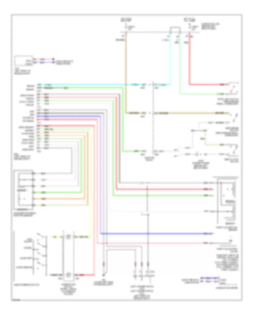
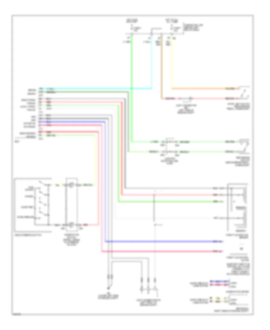
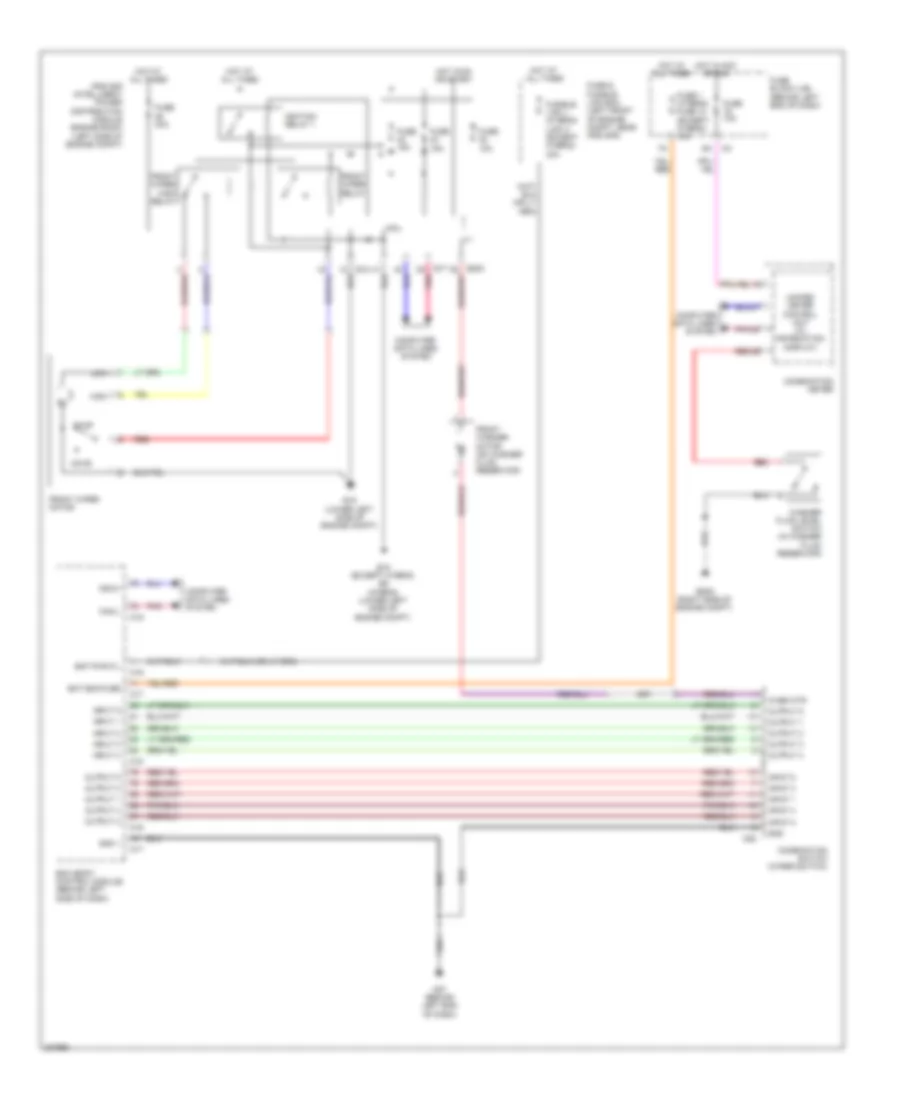
CRUISE CONTROL Cruise Control Wiring Diagram, Except Hybrid for Nissan Altima SE 2009 List of elements for Cruise Control Wiring Diagram, Except Hybrid for Nissan Altima SE 2009: 63 (2.5l) (3.5l) 8p e6 A/t Accel/resume Accelerator pedal position sensor Aps1 Aps2 Ascd brake switch (above brake pedal, on bracket) Ascd clutch switch Ascd steering switch Ascdsw Avcc1-aps1 Avcc1-tps-b1 Avcc2-aps2 Bncsw Brake Can-h Can-l Cancel Coast/set Combination meter Combination switch (spiral cable) (in steering column) Computer data lines system E10 E44 E45 E46 E9 (lower left side of engine compt) Ecm (left front of engine compt) Electric throttle control actuator (2.5l: integral with throttle body, on intake manifold) (3.5l: integral with throttle body) F13 F14 Fuse 3 10a Fuse 7 10a Fuse block (j/b) (behind left end of dash) Gnd Gnda-aps1 Gnda-aps2 Gnda-ascdsw Gnda-tps-b1 Hot at all all times Hot in on or start Joint connector e06 (behind left end of dash) Joint connector f04 (3.5l) joint connector f01 (2.5l) (left front of engine compt) Junction block M/t M30 M88 Main (on/off) Motor1-b1 Motor2-b1 Nca Pnk Red Sensor 1 Sensor 2 Stop light switch (above brake pedal, on bracket) Tcm (left front of engine compt) Throttle control motor Throttle position sensor Tps1-b1 Tps2-b1 Cruise Control Wiring Diagram, Hybrid for Nissan Altima SE 2009 List of elements for Cruise Control Wiring Diagram, Hybrid for Nissan Altima SE 2009: 50 8p e6 Accel/resume Ascd brake switch (above brake pedal, on bracket) Ascd steering switch Ascdsw Avcc1-tps-b1 Bncsw Brake Brake ecu (right rear of engine compt) Can-h Can-l Cancel Coast/set Combination meter Combination switch (spiral cable) (in steering column) Computer data lines system E10 E45 E46 E48 E9 (lower left side of engine compt) Ecm Electric throttle control actuator (integral with throttle body, on intake manifold) F13 F14 Fuse 3 10a Fuse 7 10a Fuse block (j/b) (behind left end of dash) Gnd Gnda-ascdsw Gnda-tps-b1 Hot at all all times Hot in on or start Joint connector e04 (left side of engine compt) Joint connector f03 (left front of engine compt) Junction block e45, e46 & e48 M30 M88 Main (on/off) Motor1-b1 Motor2-b1 Pnk Red Sensor 1 Sensor 2 Stop light switch (above brake pedal, on bracket) Throttle control motor Throttle position sensor Tps1-b1 Tps2-b1
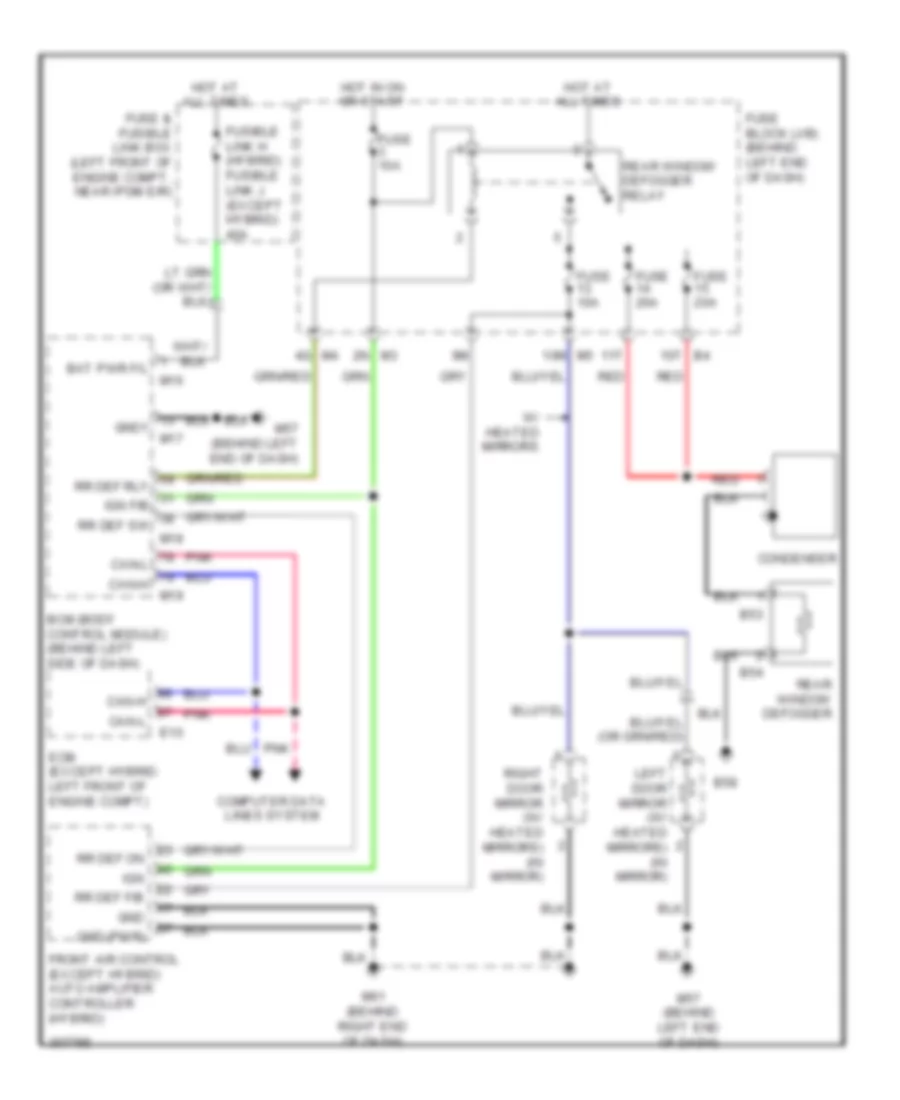
DEFOGGERS Defoggers Wiring Diagram for Nissan Altima SE 2009 List of elements for Defoggers Wiring Diagram for Nissan Altima SE 2009: 46 10m m5 10t b4 11t 2n m3 4q m4 B53 B54 B58 Bat pwr f/l Bcm (body control module) (behind left side of dash) Can-h Can-l Computer data lines system Condenser E10 Ecm (except hybrid: left front of engine compt) Front air control (except hybrid) auto amplifier controller (hybrid) Fuse & fusible link box (left front of engine compt, near ipdm e/r) Fuse 10a Fuse 20a Fuse block (j/b) (behind left end of dash) Fusible link h (hybrid) fusible link j (except hybrid) 40a Gnd Gnd (pwr) Gnd1 Hot at all times Hot in on or start Ign Ign f/b Left door mirror (w/ heated mirrors) (in mirror) M16 M17 M18 M19 M57 (behind left end of dash) M61 (behind right end of dash) Pnk Rear window defogger Rear window defogger relay Red Right door mirror (w/ heated mirrors) (in mirror) Rr def f/b Rr def on Rr def rly Rr def sw W/ heated mirrors
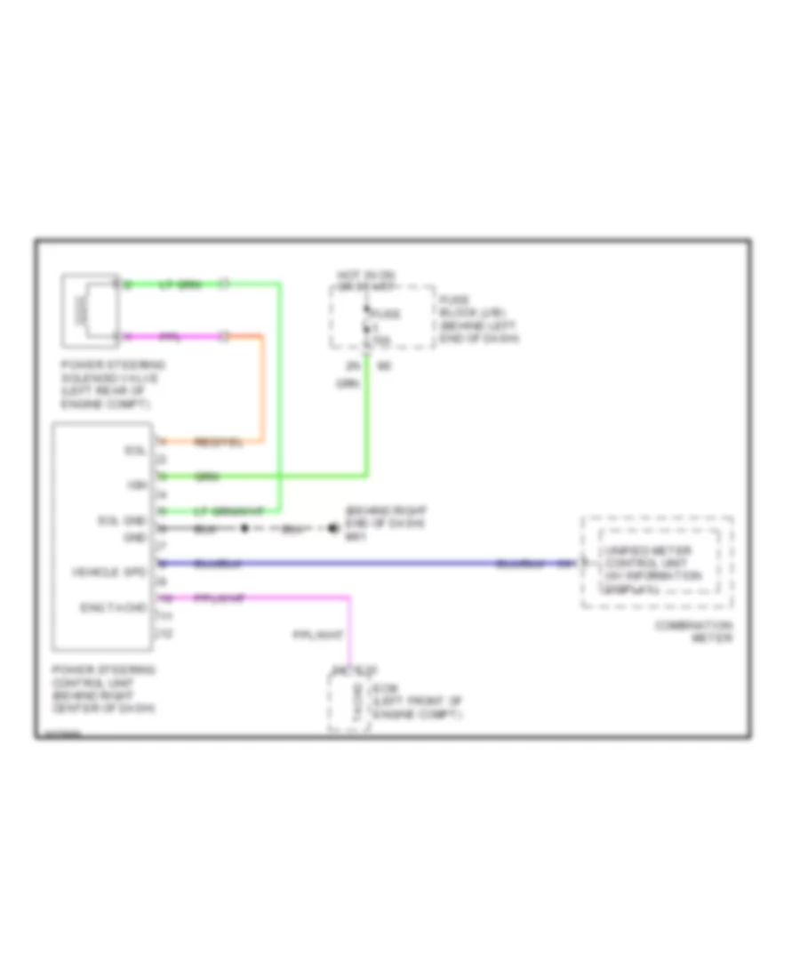
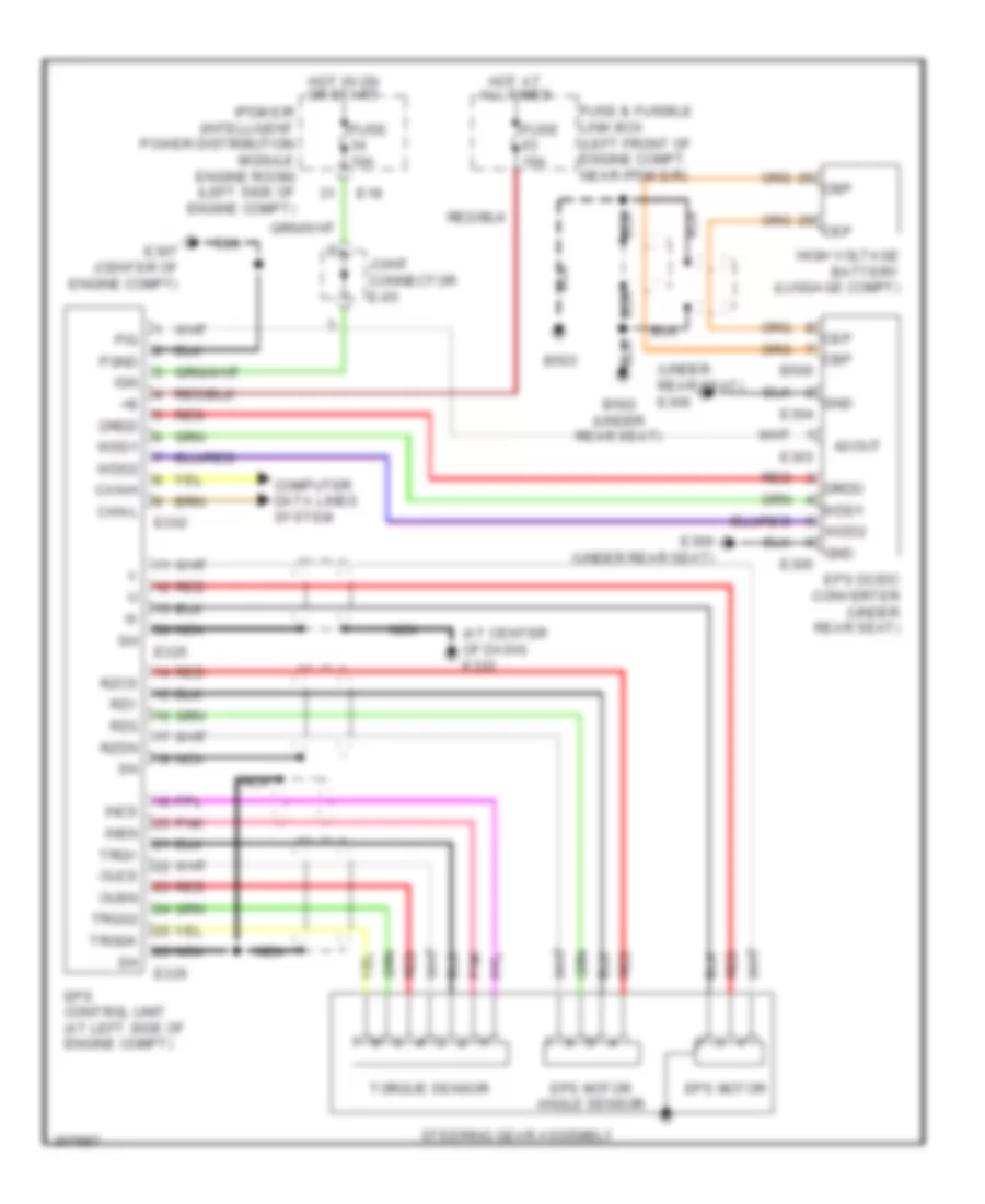
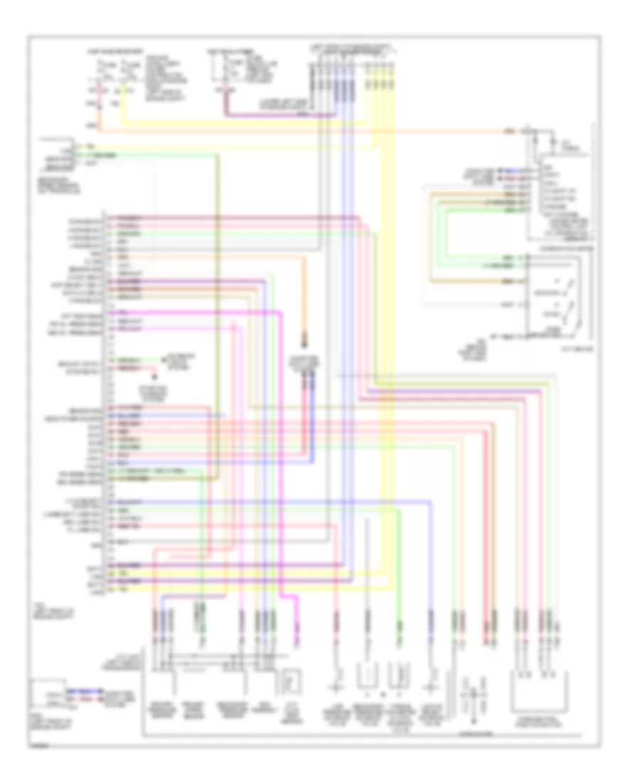
ELECTRONIC POWER STEERING Electronic Power Steering Wiring Diagram, Except Hybrid for Nissan Altima SE 2009 List of elements for Electronic Power Steering Wiring Diagram, Except Hybrid for Nissan Altima SE 2009: 17 (behind right end of dash) m61 Combination meter E10 Ecm (left front of engine compt) Eng tacho Fuse 10a Fuse block (j/b) (behind left end of dash) Gnd Hot in on or start Ign Power steering control unit (behind right center of dash) Power steering solenoid valve (left rear of engine compt) Sol Sol gnd Tacho Unified meter control unit (w/ information display) Vehicle spd Electronic Power Steering Wiring Diagram, Hybrid for Nissan Altima SE 2009 List of elements for Electronic Power Steering Wiring Diagram, Hybrid for Nissan Altima SE 2009: 54 (at center of dash) e332 (under rear seat) e306 42-out B500 B502 (under rear seat) B503 Can-h Can-l Cbp Cep Computer data lines system Drdd E18 E302 E303 E304 E305 E306 (under rear seat) E307 (center of engine compt) E325 E326 Eps control unit (at left side of engine compt) Eps dc/dc converter (under rear seat) Eps motor Eps motor angle sensor Fuse & fusible link box (left front of engine compt, near ipdm e/r) Fuse 10a Gnd High voltage battery (luggage compt) Hot at all times Hot in on or start Ign Incs Insn Ipdm e/r (intelligent power distribution module engine room) (left side of engine compt) Joint connector e-05 Nca Oucs Ousn Pgnd Pig Pnk Red Rzcs Rzg Rzsn Rzv Steering gear assembly Torque sensor Trqg2 Trqgk Trqv Wdd1 Wdd2
ENGINE PERFORMANCE
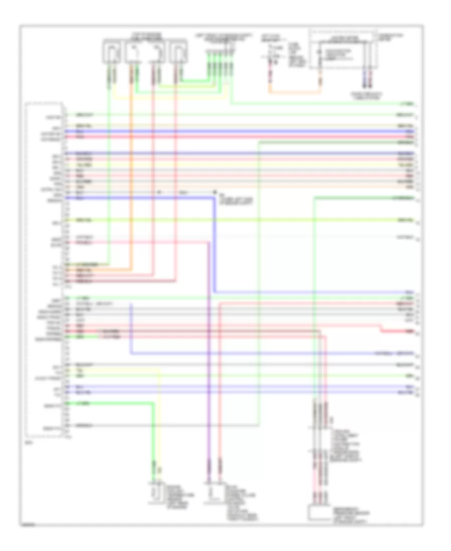
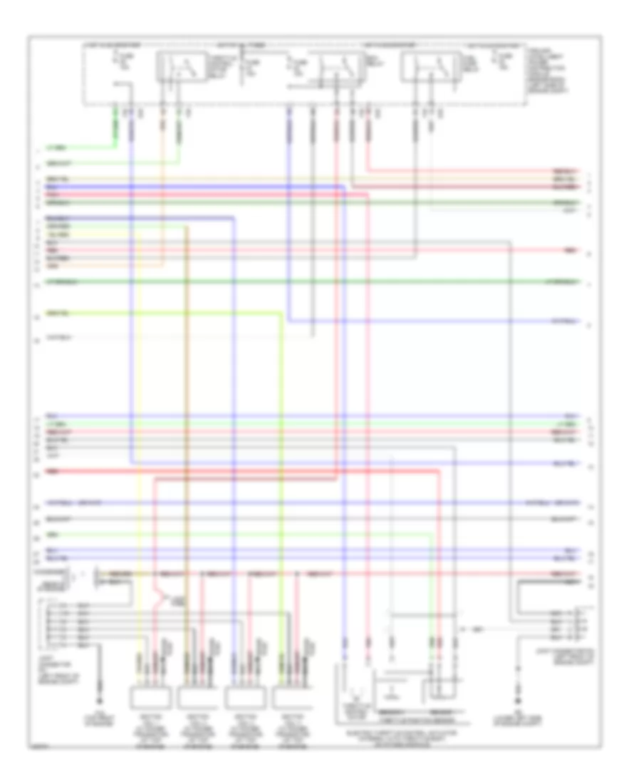
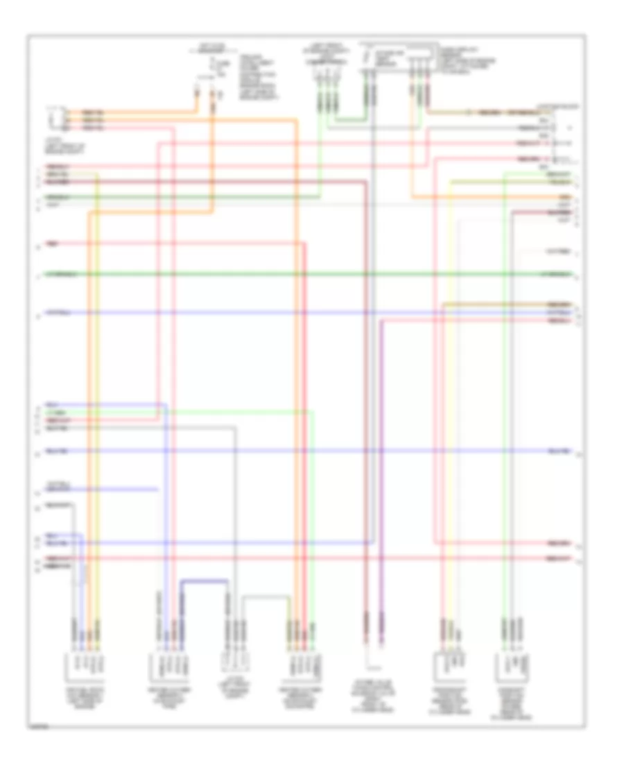
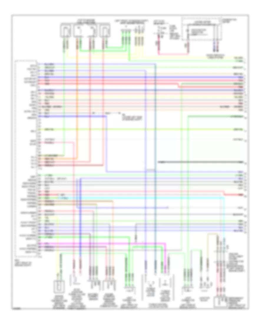
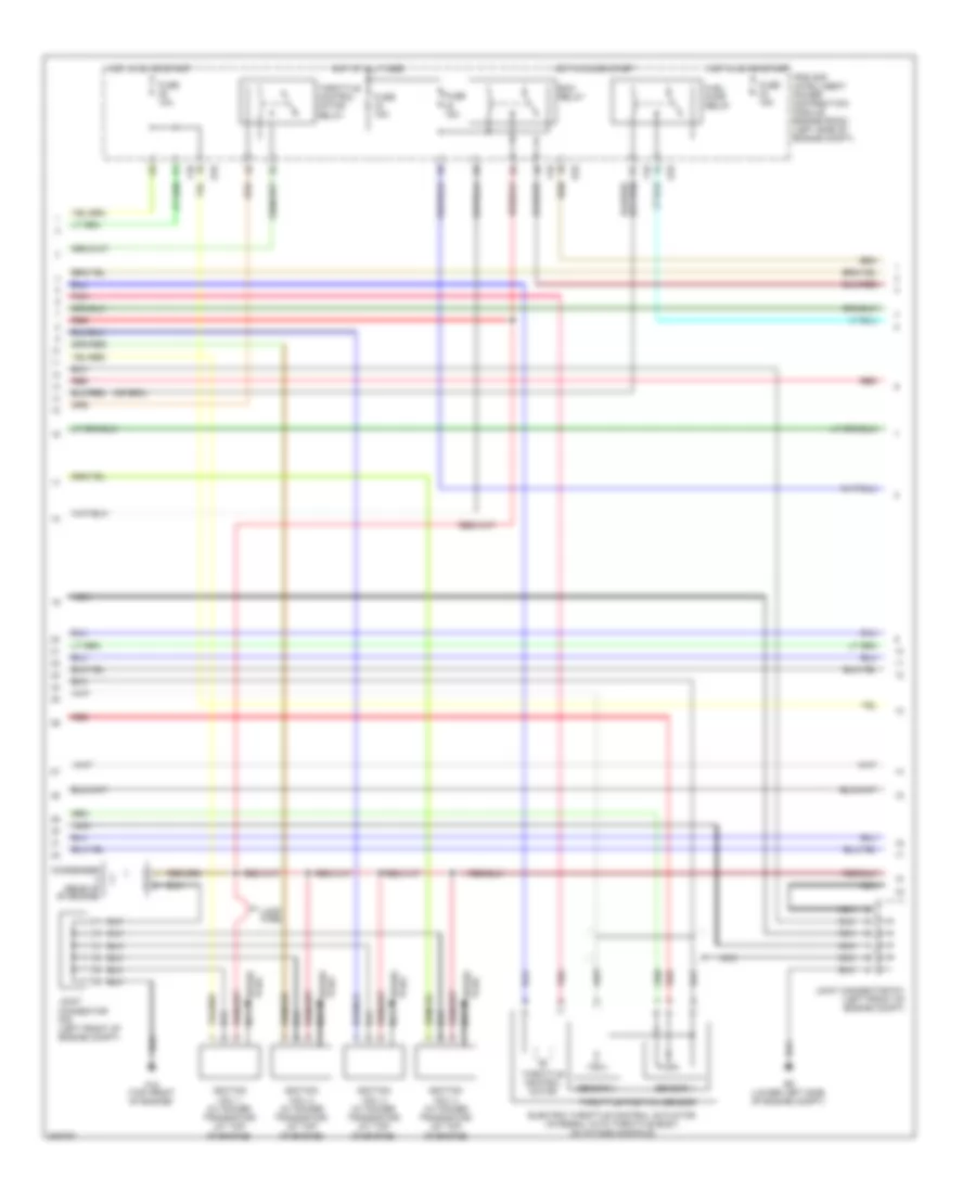
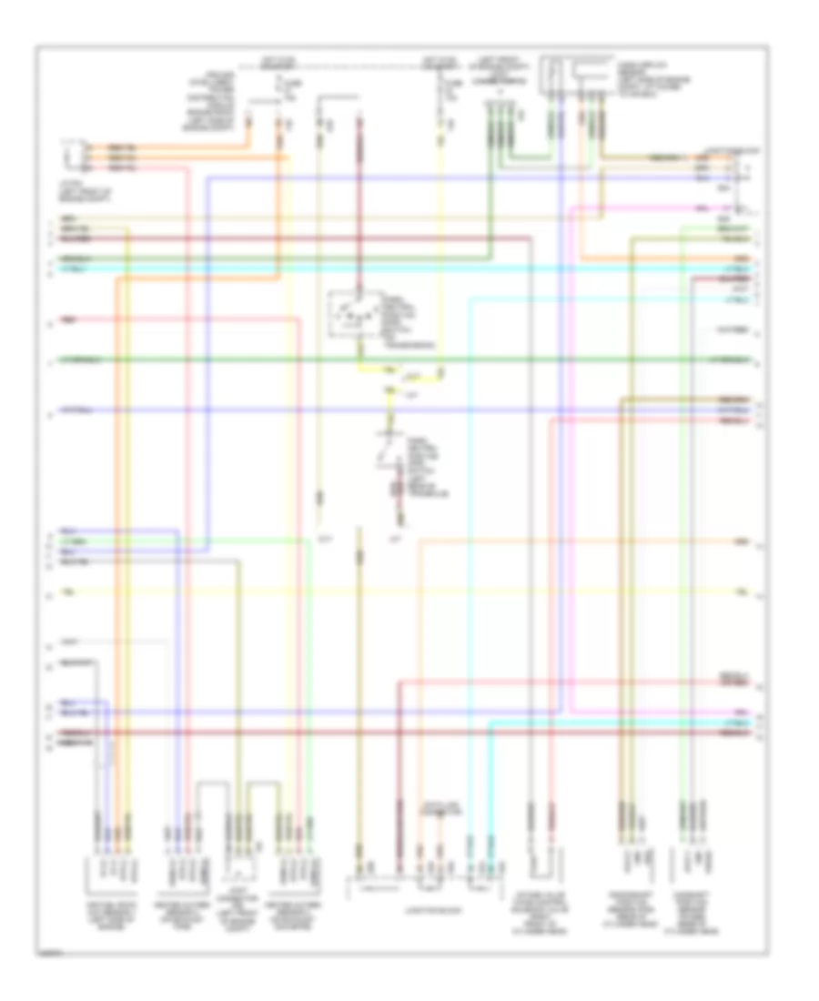
2.5L 2.5L, Engine Controls Wiring Diagram, Hybrid (1 of 4) for Nissan Altima SE 2009 List of elements for 2.5L, Engine Controls Wiring Diagram, Hybrid (1 of 4) for Nissan Altima SE 2009: 56 (behind left end of dash) (left front of engine compt) joint connector f05 (top of engine) fuel injectors 12m 3rdo2h 3rdo2s Af+1 Af-1 Afh1 Avcc1-tps-b1 Combination meter Computer data lines system E18 E201 E9 (lower left side of engine compt) Ecm Engine coolant temperature sensor (left rear of engine) Evap Evap canister purge volume control solenoid valve (on intake manifold, near throttle body) F13 F14 Fpr Fuse 10a Fuse block (j/b) Gnd Gnda-o2sr2 Gnda-pdpres Gnda-ta1 Gnda-tps-b1 Gnda-tw Hot in on or start Ign 1 Ign 2 Ign 3 Ign 4 Inj 1 Inj 2 Inj 3 Inj 4 Ipdm e/r (intelligent power distribution module engine room) (left side of engine compt) Malfunction indicator lamp Motor1-b1 Motor2-b1 Motrly-b1 O2hr1 Osr1 Pdpres Pnk Red Refrigerant pressure sensor (left front of engine compt) Ssof Ta1 Tps1-b1 Tps2-b1 Unified meter (w/ information display) Vmot-b1 2.5L, Engine Controls Wiring Diagram, Hybrid (2 of 4) for Nissan Altima SE 2009 List of elements for 2.5L, Engine Controls Wiring Diagram, Hybrid (2 of 4) for Nissan Altima SE 2009: 29 Condenser (rear of of engine) E18 E9 (lower left side of engine compt) Ecm relay Electric throttle control actuator (integral with throttle body, on intake manifold) F10 F15 (top front of engine) Fuel pump relay Fuse 10a Fuse 15a Hot at all times Hot in on or start Ignition coil 1 (w/ power transistor) (at top of engine) Ignition coil 2 (w/ power transistor) (at top of engine) Ignition coil 3 (w/ power transistor) (at top of engine) Ignition coil 4 (w/ power transistor) (at top of engine) Ipdm e/r (intelligent power distribution module engine room) (left side of engine compt) Joint connector f01 (left front of engine compt) Joint connector f03 (left front of engine compt) Loop wire Nca Pnk Red Sensor 1 Sensor 2 Spark plug Throttle control motor Throttle control motor relay Throttle position sensor 2.5L, Engine Controls Wiring Diagram, Hybrid (3 of 4) for Nissan Altima SE 2009 List of elements for 2.5L, Engine Controls Wiring Diagram, Hybrid (3 of 4) for Nissan Altima SE 2009: 31 (left front of engine compt) joint connector f03 Af (+) Af (-) Air fuel ratio (a/f) sensor 1 (left side of engine) Avcc1 Avcc2 Camshaft position sensor (phase) (rear of cylinder head) Crankshaft position sensor (pos) (rear of cylinder head) E44 E45 F10 Fuse 15a Gnd Heated oxygen sensor 2 (on exhaust downpipe) Heated oxygen sensor 3 (in exhaust pipe) Hot in on or start Htr (+) Htr (-) Intake air temp sensor Intake valve timing control solenoid valve (right front of cylinder head) Ipdm e/r (intelligent power distribution module engine room) (left side of engine compt) J/c f01 (left front of engine compt) J/c f03 (left front of engine compt) Junction block Mass airflow sensor (left side of engine compt, attached to air box) Nca Phase Pos Red Sens (+) Sens (-) 2.5L, Engine Controls Wiring Diagram, Hybrid (4 of 4) for Nissan Altima SE 2009 List of elements for 2.5L, Engine Controls Wiring Diagram, Hybrid (4 of 4) for Nissan Altima SE 2009: 62 (base of left "c" pillar) joint connector b03 Ascdsw Avcc1-phase 1 Avcc2 Avcc2-ftpres Avcc2-pdpres Avcc2-pos B19 (at left "c" pillar) Batt Bncsw Brake Can-h Can-l Cdcv Computer data lines system Condenser Cruise control system Cvtc 1 E10 E15 (lower left side of engine compt) E44 E45 E66 E9 (lower left side of engine compt) Ecm Evap canister vent control valve (below center rear of vehicle, near evap canister) Evap control system pressure sensor (below center rear of vehicle, near evap canister) F13 Ftpres Fuel level sensor unit & fuel pump (in fuel tank) Fuel pump Fuel tank temperature sensor Fuse 10a Fuse block (j/b) (behind left end of dash) Gnd Gnd-phase 1 Gnd-pos Gnda-ascdsw Gnda-ftpres Gnda-knk1 Gnda-tf Hot at all times Hybrid vehicle control ecu (center of dash) Ignsw J/c e04 (left side of engine compt) Joint connector e01 (left front engine compt) Joint connector e08 Junction block Kline Knk1 Knock sensor (right side of cylinder head) Nca Neo Phase Phase 1 Pnk Pos Qa+ Red Sig Stop light switch (above brake pedal, on bracket) Vbr 2.5L, Engine Performance Wiring Diagram, California Except Hybrid (1 of 4) for Nissan Altima SE 2009 List of elements for 2.5L, Engine Performance Wiring Diagram, California Except Hybrid (1 of 4) for Nissan Altima SE 2009: 81 (behind left end of dash) (left front of engine compt) joint connector f04 (top of engine) fuel injectors 12m 3rdo2s Af+1 Af-1 Afh1 Avcc1 Avcc1-cursen Avcc1-pspres Avcc1-tps-b1 Avcc2 Battery current sensor Combination meter Computer data lines system Cursen E18 E44 E45 E9 (lower left side of engine compt) Ecm (left front of engine compt) Engine coolant temperature sensor (left rear of engine) Engine room) (left side of engine compt) Evap Evap canister purge volume control solenoid valve (on intake manifold, near throttle body) F13 F14 Fpr Fuse 10a Fuse block (j/b) Gnd Gnda-cursen Gnda-o2sr2 Gnda-pdpres Gnda-pspres Gnda-ta1 Gnda-tps-b1 Gnda-tw Hot in on or start Ign 1 Ign 2 Ign 3 Ign 4 Inj 1 Inj 2 Inj 3 Inj 4 Ipdm e/r (intelligent power distribution module e201 Joint connector f06 (left front of engine compt) Joint connector f07 (left side of engine compt) Junction block Malfunction indicator lamp Motor1-b1 Motor2-b1 Motrly-b1 Nca O2hr1 Osr1 Output Pdpres Pnk Power steering pressure sensor (on power steering pump) Pspres Red Refrigerant pressure sensor (left front of engine compt) Scv1 Scv2 Scvpos Sig Srdo2h Ssof Ta1 Tps1-b1 Tps2-b1 Tumble control valve actuator Tumble control valve motor Tumble control valve position sensor Unified meter (w/ information display) Vmot-b1 Vscv 2.5L, Engine Performance Wiring Diagram, California Except Hybrid (2 of 4) for Nissan Altima SE 2009 List of elements for 2.5L, Engine Performance Wiring Diagram, California Except Hybrid (2 of 4) for Nissan Altima SE 2009: 29 Condenser (rear of of engine) E18 E9 (lower left side of engine compt) Ecm relay Electric throttle control actuator (integral with throttle body, on intake manifold) F10 F15 (top front of engine) Fuel pump relay Fuse 10a Fuse 15a Hot at all times Hot in on or start Ignition coil 1 (w/ power transistor) (at top of engine) Ignition coil 2 (w/ power transistor) (at top of engine) Ignition coil 3 (w/ power transistor) (at top of engine) Ignition coil 4 (w/ power transistor) (at top of engine) Ipdm e/r (intelligent power distribution module engine room) (left side of engine compt) Joint connector f01 (left front of engine compt) Joint connector f05 (left front of engine compt) Loop wire Nca Pnk Red Sensor 1 Sensor 2 Spark plug Throttle control motor Throttle control motor relay Throttle position sensor 2.5L, Engine Performance Wiring Diagram, California Except Hybrid (3 of 4) for Nissan Altima SE 2009 List of elements for 2.5L, Engine Performance Wiring Diagram, California Except Hybrid (3 of 4) for Nissan Altima SE 2009: 40 (left front of engine compt) joint connector f06 Af (+) Af (-) Air fuel ratio (a/f) sensor 1 (left side of engine) Avcc1 Avcc2 Camshaft position sensor (phase) (rear of cylinder head) Crankshaft position sensor (pos) (rear of cylinder head) Cvt Data link connector E18 E44 E45 E46 E50 F10 F52 Fuse 10a Fuse 15a Gnd Heated oxygen sensor 2 (on exhaust downpipe) Heated oxygen sensor 3 (on exhaust pipe) Hot in on or start Htr (+) Htr (-) Intake valve timing control solenoid valve (right front of cylinder head) Ipdm e/r (intelligent power distribution module engine room) (left side of engine compt) J/c f04 (left front of engine compt) Joint connector f06 (left front of engine compt) Junction block M/t Mass airflow sensor (left side of engine compt, attached to air box) Nca Park/ neutral position (pnp) switch (left rear of transaxle) Park/ neutral position (pnp) switch (on transmission) Phase Pos Red Sens (+) Sens (-) 2.5L, Engine Performance Wiring Diagram, California Except Hybrid (4 of 4) for Nissan Altima SE 2009 List of elements for 2.5L, Engine Performance Wiring Diagram, California Except Hybrid (4 of 4) for Nissan Altima SE 2009: 68 (base of left "c" pillar) joint connector b03 (or red) Accelerator pedal sensor (above accelerator pedal, on bracket) Aps1 Aps2 Ascdsw Avcc1-aps1 Avcc1-phase 1 Avcc2 Avcc2-aps2 Avcc2-ftpres Avcc2-pdpres Avcc2-pos B19 (at left "c" pillar) Batt Bncsw Brake Can-h Can-l Cdcv Computer data lines system Condenser Cruise control system Cvtc 1 E10 E44 E45 E9 (lower left side of engine compt) Ecm (left front of engine compt) Eng tach Evap canister vent control valve (below center rear of vehicle, near evap canister) Evap control system pressure sensor (below center rear of vehicle, near evap canister) F13 Ftpres Fuel level sensor unit & fuel pump (in fuel tank) Fuel pump Fuse 10a Fuse block (j/b) (behind e6 left end of dash) Gnd Gnd-phase 1 Gnd-pos Gnda-aps1 Gnda-aps2 Gnda-ascdsw Gnda-ftpres Gnda-knk1 Gnda-tf Hot at all times Ignsw Intake tank temperature sensor Junction block Kline Knk1 Knock sensor (right side of cylinder head) Nca Neut-h Phase 1 Pnk Pos Power steering control unit (behind right center of dash) Qa1 + Red Sensor 1 Sensor 2 Sig Stop light switch (above brake pedal, on bracket) Tacho (cabin) Vbr 2.5L, Engine Performance Wiring Diagram, Except California Except Hybrid (1 of 4) for Nissan Altima SE 2009 List of elements for 2.5L, Engine Performance Wiring Diagram, Except California Except Hybrid (1 of 4) for Nissan Altima SE 2009: 69 (behind left end of dash) (left front of engine compt) joint connector f04 (or red) (top of engine) fuel injectors 12m Af+1 Af-1 Afh1 Avcc1 Avcc1-cursen Avcc1-pspres Avcc1-tps-b1 Battery current sensor Combination meter Computer data lines system Cursen E18 E44 E45 E9 (lower left side of engine compt) Ecm (left front of engine compt) Engine coolant temperature sensor (left rear of engine) Evap Evap canister purge volume control solenoid valve (on intake manifold, near throttle body) F13 F14 Fpr Fuse 10a Fuse block (j/b) Gnd Gnda-cursen Gnda-o2sr2 Gnda-pdpres Gnda-pspres Gnda-ta1 Gnda-tps-b1 Gnda-tw Hot in on or start Ign 1 Ign 2 Ign 3 Ign 4 Inj 1 Inj 2 Inj 3 Inj 4 Ipdm e/r power (intelligent distribution e201 Junction block Malfunction indicator lamp Module engine room) (left side of engine compt) Motor1-b1 Motor2-b1 Motrly-b1 O2hr1 Osr1 Output Pdpres Pnk Power steering pressure sensor (on power steering pump) Pspres Red Refrigerant pressure sensor (left front of engine compt) Sig Ssof Ta1 Tps1-b1 Tps2-b1 Unified meter control unit w/ information display Vmot-b1 2.5L, Engine Performance Wiring Diagram, Except California Except Hybrid (2 of 4) for Nissan Altima SE 2009 List of elements for 2.5L, Engine Performance Wiring Diagram, Except California Except Hybrid (2 of 4) for Nissan Altima SE 2009: 30 Condenser (rear of of engine) E18 E9 (lower left side of engine compt) Ecm relay Electric throttle control actuator (integral with throttle body, on intake manifold) F10 F15 (top front of engine) Fuel pump relay Fuse 10a Fuse 15a Hot at all times Hot in on or start Ignition coil 1 (w/ power transistor) (at top of engine) Ignition coil 2 (w/ power transistor) (at top of engine) Ignition coil 3 (w/ power transistor) (at top of engine) Ignition coil 4 (w/ power transistor) (at top of engine) Ipdm e/r (intelligent power distribution module engine room) (left side of engine compt) J/c f01 (left front of engine compt) Joint connector f05 (left front of engine compt) Loop wire Nca Plug spark Pnk Red Sensor 1 Sensor 2 Spark plug Throttle control motor Throttle control motor relay Throttle position sensor 2.5L, Engine Performance Wiring Diagram, Except California Except Hybrid (3 of 4) for Nissan Altima SE 2009 List of elements for 2.5L, Engine Performance Wiring Diagram, Except California Except Hybrid (3 of 4) for Nissan Altima SE 2009: 37 (left front of eng compt) joint connector f06 (or red) Af (+) Af (-) Air fuel ratio (a/f) sensor 1 (left side of engine) Avcc1 Avcc2 Camshaft position sensor (phase) (rear of cylinder head) Crankshaft position sensor (pos) (rear of cylinder head) Cvt Data link connector E18 E44 E45 E46 E50 F10 F52 Fuse 10a Fuse 15a Gnd Heated oxygen sensor 2 (on exhaust downpipe) Hot in on or start Htr (+) Htr (-) Intake valve timing control solenoid valve (right front of cylinder head) Ipdm e/r (intelligent power distribution module engine room) (left side of engine compt) Junction block M/t Mass airflow sensor (left side of engine compt, attached to air box) Nca Park/ neutral position (pnp) switch (left rear of transaxle) Park/ neutral position (pnp) switch (on transmission) Pos Red Snsr (+) Snsr (-) 2.5L, Engine Performance Wiring Diagram, Except California Except Hybrid (4 of 4) for Nissan Altima SE 2009 List of elements for 2.5L, Engine Performance Wiring Diagram, Except California Except Hybrid (4 of 4) for Nissan Altima SE 2009: 67 (base of left "c" pillar) joint connector b03 (or red) Accelerator pedal sensor (above accelerator pedal, on bracket) Aps1 Aps2 Ascdsw Avcc1-aps1 Avcc1-phase 1 Avcc2 Avcc2-aps2 Avcc2-ftpres Avcc2-pdpres Avcc2-pos B19 (at left "c" pillar) Batt Bncsw Brake Can-h Can-l Cdcv Computer data lines system Condenser Cruise control system Cvtc 1 E10 E44 E45 E9 (lower left side of engine compt) Ecm (left front of engine compt) Eng tacho Evap canister vent control valve (below center rear of vehicle, near evap canister) Evap control system pressure sensor (below center rear of vehicle, near evap canister) F13 Ftpres Fuel level sensor unit & fuel pump (in fuel tank) Fuel pump Fuse 10a Fuse block (j/b) (behind e6 left end of dash) Gnd Gnd-phase 1 Gnd-pos Gnda-aps1 Gnda-aps2 Gnda-ascdsw Gnda-ftpres Gnda-knk1 Gnda-tf Hot at all times Ignsw Junction block Kline Knk1 Knock sensor (right side of cylinder head) Nca Neut-h Phase 1 Pnk Pos Power steering control unit (behind right center of dash) Qa1+ Red Sensor 1 Sensor 2 Sig Stop light switch (above brake pedal, on bracket) Tacho (cabin) Vbr 2.5L, Hybrid Control Wiring Diagram (1 of 3) for Nissan Altima SE 2009 List of elements for 2.5L, Hybrid Control Wiring Diagram (1 of 3) for Nissan Altima SE 2009: 60 +bs Bcm (body control module) (behind left side of dash) Can-h Can-l Clk Computer data lines system Crf E10 E12 E15 (lower left side of engine compt) E24 E65 E9 (lower left side of engine compt) Ecm Electric compressor Eo1 Eo2 Et1 F252 F69 F77 F85 Fuse & fusible link box (left front of engine compt, near ipdm e/r) Fuse 10a Fusible link b 120a Fusible link g 50a Gcs Gcsg Gmt Gmtg Grfg Gsn Gsng Hot at all times Hybrid vehicle control ecu (center of dash) Igct relay Ite J/c e01 (left front engine compt) J/c e08 J/c fo8 M18 M21 Mcs Mcsg Mmt Mmtg Motor generator 1 (engine) Motor generator 2 (engine) Mrf Mrfg Msn Msng Nca Neo Park/neutral position (pnp) switch (m/t: left rear of transaxle) (w/ cvt: on transmission) Pnk Red Shnp Stb Water pump w/ motor & bracket assembly 2.5L, Hybrid Control Wiring Diagram (2 of 3) for Nissan Altima SE 2009 List of elements for 2.5L, Hybrid Control Wiring Diagram (2 of 3) for Nissan Altima SE 2009: 60 Acpb (+) Acpe (-) Anti-lock brakes system Ascd brake switch (above brake pedal, on bracket) Avcc1 Avcc2 B117 (at right "c" pillar) B130 B309 B310 B311 B312 B500 B501 B502 (under rear seat) B503 Backup lamp relay Backup lp rly Battery cooling blower assembly Bncsw Bth+ Bth- Cbi Cbp Cei Cep Con2 Con3 Connsw E308 E313 E44 E46 E48 E50 E66 Eps dc/dc converter (under rear seat) F250 Gnd Hi volt (+) Hi volt (-) High voltage battery (luggage compt) Hsdn Hybrid vehicle control ecu (center of dash) Igct Ilk Inverter (left side of engine compt) Iwp Junction block Nca Nodd Nodo Phase Pnk Pos Red Sio Smrp Spdi Vlo 2.5L, Hybrid Control Wiring Diagram (3 of 3) for Nissan Altima SE 2009 List of elements for 2.5L, Hybrid Control Wiring Diagram (3 of 3) for Nissan Altima SE 2009: 81 +b2 Accelerator pedal position switch (above accelerator pedal, on bracket) Aps1 Aps2 Batt Brake Bth+ Bth- Can-1h Can-1l Can-2h Can-2l Clk+ Clk- Computer data lines system E18 E24 E44 E45 E66 E69 E9 (lower left side of engine compt) F79 Fctl Fuse & fusible link box (left front of engine compt, near ipdm e/r) Fuse 10a Fuse 15a Fuse block (j/b) (behind left end of dash) Gcs Gcsg Gnd-a1 Gnd-a2 Gnd1 Gnd2 Grf Grfg Gsn Gsng High voltage battery fan relay Hot at all times Hot in on or start Hsdn Htm+ Htm- Hybrid vehicle control ecu (center of dash) Igsw Ilki Ilko Ipdm e/r (intelligent power distribution module engine room) (left side of engine compt) Ivcs J/c b01 (near base of left b-pillar) J/c e04 (left side of engine compt) J/c e05 J/c e09 (left rear engine compt) Junction block Mcs Mcsg Mg ecu inverter (left front of engine compt) Mrf Mrfg Msn Msng Mth+ Mth- Nca Phase Pnk Red Req+ Req- Smrb Smrg Ssoff St2 Stop light switch (above brake pedal, on bracket) Vbr1 Vbr2 Vc1 Vc2 Vpa1 Vpa2
3.5L 3.5L, Engine Performance Wiring Diagram (1 of 4) for Nissan Altima SE 2009 List of elements for 3.5L, Engine Performance Wiring Diagram (1 of 4) for Nissan Altima SE 2009: 86 (left side of engine compt) joint connector f07 Af (+) Af (-) Af+1 Af+2 Af-1 Af-2 Afh1 Afh2 Air fuel ratio (a/f) sensor 1 (bank 2) (left side of engine) Avcc1 Avcc1-cursen Avcc1-pspres Avcc1-tps-b1 Avcc2 Battery current sensor Cursen E18 E44 E45 E46 E9 (lower left side of engine compt) Ecm (left front of engine compt) Electronic controlled engine mount control solenoid valve Emmnv Engine compt) Engine coolant temperature sensor (upper rear of engine) Engine oil temperature sensor (lower right front of engine) Evap Evap canister purge volume control solenoid valve (top rear of engine) F13 F14 Fpr Fuel injectors (inj 1, 3, 5: top of right cylinder bank) (inj 2, 4, 6: top of left cylinder bank) Fuse 10a Fuse block (j/b) (behind left end of dash) Gnd Gnda-cursen Gnda-o2sr1 & 2 Gnda-pdpres Gnda-pspres Gnda-tps-b1 Gnda-tw Hot in on or start Htr (+) Htr (-) Ign 1 Ign 2 Ign 3 Ign 4 Ign 5 Ign 6 Inj 1 Inj 2 Inj 3 Inj 4 Inj 5 Inj 6 Ipdm e/r (intelligent power distribution module engine room) (left side of e201 Joint connector f01 (left side of engine compt) Joint connector f08 Junction block Motor1-b1 Motor2-b1 Motrly-b1 Nca O2hr1 O2hr2 O2sr1 O2sr2 Pdpres Pnk Power steering pressure sensor (on power steering pump) Pspres Qa1, gnda-ta1 Red Refrigerant pressure sensor (left front of engine compt) Sig Ssoff Ta1 To1 Tps1-b1 Tps2-b1 Vias 1 Vias 2 Vmot-b1 3.5L, Engine Performance Wiring Diagram (2 of 4) for Nissan Altima SE 2009 List of elements for 3.5L, Engine Performance Wiring Diagram (2 of 4) for Nissan Altima SE 2009: 32 (ignition coils: 1, 3 & 5 top of right cylinder bank) (ignition coils: 2, 4 & 6 top of left cylinder bank) (integral with throttle body) Condenser 2 (left rear of of engine) E18 E9 (lower left side of engine compt) Ecm relay Electric throttle control actuator F10 F15 (top front of engine) Fuel pump relay Fuse 10a Fuse 15a Hot at all times Hot in on or start Ignition coil 1 (w/ power transistor) Ignition coil 2 (w/ power transistor) Ignition coil 3 (w/ power transistor) Ignition coil 4 (w/ power transistor) Ignition coil 5 (w/ power transistor) Ignition coil 6 (w/ power transistor) Ipdm e/r (intelligent power distribution module engine room) (left side of engine compt) Joint connector f01 (left side of engine compt) Loop wire Nca Plug spark Pnk Red Sensor 1 Sensor 2 Throttle control motor Throttle control motor relay Throttle position sensor 3.5L, Engine Performance Wiring Diagram (3 of 4) for Nissan Altima SE 2009 List of elements for 3.5L, Engine Performance Wiring Diagram (3 of 4) for Nissan Altima SE 2009: 46 (left front of engine compt) joint connector f06 (or red) Af (+) Af (-) Air fuel ratio (a/f) sensor 1 (bank 1) (right side of engine) Avcc1 Avcc2 Camshaft position sensor (phase) (bank 1) (rear of right cylinder head) Camshaft position sensor (phase) (bank 2) (rear of left cylinder head) Crankshaft position sensor (pos) (lower left rear of engine) Cvt Data link connector E18 E44 E45 E46 E50 F10 F52 Fuse 10a Fuse 15a Gnd Heated oxygen sensor 2 (bank 1) (right rear of engine compt) Heated oxygen sensor 2 (bank 2) (on left exhaust downpipe) Hot in on or start Htr (+) Htr (-) Intake air temp sensor Intake valve timing control solenoid valve (bank 1) (front of right cylinder head) Intake valve timing control solenoid valve (bank 2) (front of left cylinder head) Ipdm e/r (intelligent power distribution module engine room) (left side of engine compt) Joint connector f01 (left side of engine compt) Joint connector f03 (right rear of engine compt) Junction block M/t Mass airflow sensor (left rear of engine compt) Nca Park/ neutral position (pnp) switch (left rear of transaxle) Phase Pos Red Sens (+) Sens (-) Transmission control module (left front of engine compt) Vias control solenoid valve 1 Vias control solenoid valve 2 (top of left cylinder bank) 3.5L, Engine Performance Wiring Diagram (4 of 4) for Nissan Altima SE 2009 List of elements for 3.5L, Engine Performance Wiring Diagram (4 of 4) for Nissan Altima SE 2009: 81 (base of left "c" pillar) joint connector b03 (left side of engine compt) joint connector f01 (lower left side of engine compt) e15 (on engine block, below intake manifold) (or red) 12m Accelerator pedal position sensor (above accelerator pedal, on bracket) Aps1 Aps2 Ascdsw Avcc1-aps1 Avcc1-phase 1 Avcc1-phase 2 Avcc2-aps2 Avcc2-ftpres Avcc2-pdpres Avcc2-pos B19 (at left "c" pillar) Batt Bncsw Brake Can-h Can-l Cdcv Combination meter Computer data lines system Condenser Cruise control system Cvtc 1 Cvtc 2 E10 E44 E45 E9 (lower left side of engine compt) Ecm (left front of engine compt) Eng tach Evap canister vent control valve (below center rear of vehicle, near evap canister) Evap control system pressure sensor (below center rear of vehicle, near evap canister) F13 Ftpres Fuel level sensor unit & fuel pump (in fuel tank) Fuel pump Fuse 10a Fuse block (j/b) (behind left end of dash) Gnd Gnd-pos Gnda-aps1 Gnda-aps2 Gnda-ascdsw Gnda-ftpres Gnda-knk1,knk2 Gnda-phase 2 Gnda-tf Hot at all times Hot in on or start Ignsw Intake air temperature sensor Junction block Kline Knk1 Knk2 Knock sensor Malfunction indicator lamp Nca Neut-h Phase 1 Phase 2 Pnk Pos Power steering control unit (behind right center of dash) Qa1+ Red Sensor 1 Sensor 2 Stop light switch (above brake pedal, on bracket) Tacho (cabin) Unified meter (w/ information display) Vbr View monitor W/ rear W/o rear
EXTERIOR LIGHTS Backup Lamps Wiring Diagram, Except Hybrid for Nissan Altima SE 2009 List of elements for Backup Lamps Wiring Diagram, Except Hybrid for Nissan Altima SE 2009: 27 12m m5 2.5l 3.5l B19 (at left "c" pillar) Back- up Backup lamp relay (near fuse block box (j/b)) Backup lamp switch Cvt E47 E49 Fuse 4 10a Fuse block (j/b) (behind left end of dash) Hot in on or start Joint connector b07 (left side of luggage compt) Joint connector f03 (left front of engine compt) Joint connector m02 (behind center of dash) Junction block e47 & e49 Left rear combination lamp M/t M57 (behind left end of dash) Park/neutral position (pnp) switch (on transmission) Red Rev lamp rly Right rear combination lamp Transmission control module (tcm) (left front of engine compt) W/ rear view monitor W/o rear view monitor Backup Lamps Wiring Diagram, Hybrid for Nissan Altima SE 2009 List of elements for Backup Lamps Wiring Diagram, Hybrid for Nissan Altima SE 2009: 20 (left side of luggage compt) joint connector bo7 12m m5 B19 (at left "c" pillar) Back- up Backup lamp relay E24 E45 E46 E66 Fuse 4 10a Fuse block (j/b) (behind left end of dash) Hot in on or start Hybrid vehicle control ecu (center of dash) Joint connector m02 (behind center of dash) Junction block e45 & e46 Left rear combination lamp M57 (behind left end of dash) Right rear combination lamp W/ rear view monitor W/o rear view monitor Exterior Lamps Wiring Diagram, Coupe for Nissan Altima SE 2009 List of elements for Exterior Lamps Wiring Diagram, Coupe for Nissan Altima SE 2009: 85 (behind left end of dash) m57 (behind right end of dash) m61 (on left "b" pillar) b7 (w/ information display) unified meter control unit 12m As door sw B19 (at left "c" pillar) Bat bcm fuse Bat pwr f/l Body control module (bcm) (behind left side of dash) Can-h Can-l Combination meter Combination switch (lighting & turn signal switch) Computer data lines system Cpu Dr door sw E15 (lower left side of engine compt) E17 E18 E201 E204 (left side of engine compt) E209 (right side of engine compt) E217 E218 E224 E225 Fl flasher Fr flasher Fuse & fusible link box (left front of engine compt, near ipdm e/r) Fuse 10a Fuse 15a Fuse block (j/b) (behind left end of dash) Fusible link h 40a Gnd 1 Hazard sw Hazard switch High mounted stop lamp Hot at all times Hot in on or start Input 1 Input 2 Input 3 Input 4 Input 5 Intelligent power distribution module engine room (ipdm e/r) (left side of engine compt) Interior lights system J/c t01 J/c t02 (left rear body) Joint connector b06 (left front of luggage compt) Joint connector m02 (behind center of dash) Left door mirror (if equipped) (in mirror) Left front combination lamp Left license plate lamp Left rear combination lamp Left turn ind M16 M17 M18 M19 M21 M57 (behind left end of dash) M61 (behind right end of dash) Output 1 Output 2 Output 3 Output 4 Output 5 Parking Pnk Right door mirror (if equipped) (in mirror) Right front combination lamp Right license plate lamp Right rear combination lamp Right turn ind Rl door sw Rr door sw Stop Stop light switch (above brake pedal, on bracket) Tail Tail lamp relay Turn sig View monitor W/ rear W/o rear view monitor Exterior Lamps Wiring Diagram, Sedan for Nissan Altima SE 2009 List of elements for Exterior Lamps Wiring Diagram, Sedan for Nissan Altima SE 2009: 86 (w/ information display) unified meter control unit 12m As door sw B19 (at left "c" pillar) B7 (on left "b" pillar) Bat bcm fuse Bat pwr f/l Body control module (bcm) (behind left side of dash) Can-h Can-l Combination meter Combination switch Computer data lines system Cpu Dr door sw E15 (lower left side of engine compt) E17 E18 E201 E204 (left side of engine compt) E209 (right side of engine compt) E217 E218 E224 E225 Except hybrid sedan Fl flasher Fr flasher Fuse & fusible link box (left front of engine compt, near ipdm e/r) Fuse 10a Fuse 15a Fuse block (j/b) (behind left end of dash) Fusible link j (hybrid) fusible link h (except hybrid) 40a Gnd 1 Hazard sw Hazard switch High mounted stop lamp (w/ rear spoiler) High mounted stop lamp (w/o rear spoiler) Hot at all times Hot in on or start Hybrid Input 1 Input 2 Input 3 Input 4 Input 5 Intelligent power distribution module engine room (ipdm e/r) (left side of engine compt) Interior lights system J/c e04 (left side of engine compt) Joint connector b06 (left front of luggage compt) Joint connector b08 (left front of luggage compt) Joint connector m02 (behind center of dash) Left door mirror (if equipped) (in mirror) Left front combination lamp Left license plate lamp Left rear combination lamp Left turn ind M16 M17 M18 M19 M21 M57 (behind left end of dash) M61 (behind right end of dash) Output 1 Output 2 Output 3 Output 4 Output 5 Parking Pnk Right door mirror (if equipped) (in mirror) Right front combination lamp Right license plate lamp Right rear combination lamp Right turn ind Rl door sw Rr door sw Stop Stop light switch (above brake pedal, on bracket) Tail Tail lamp relay Turn sig View monitor W/ rear W/o rear view monitor
GROUND DISTRIBUTION Ground Distribution Wiring Diagram (1 of 2) for Nissan Altima SE 2009 List of elements for Ground Distribution Wiring Diagram (1 of 2) for Nissan Altima SE 2009: 19 Backup lamp relay, accelerator pedal position switch, brake ecu, hybrid vehicle control ecu, brake stroke sensor, brake actuator, brake actuator pedal pressure sensor 1 (shield) & brake actuator pedal pressure sensor 2 (shield) Brake ecu (hybrid), hybrid vehicle control ecu (shield) (hybrid), water pump w/ motor & bracket assembly (hybrid), ecm (shield) (hybrid), heater pump (hybrid), brake actuator (hybrid), steering angle sensor (hybrid), brake fluid level switch, front wiper motor, cooling fan relay 3 (except hybrid), a/c compressor (except hybrid), tcm (transmission control module) (except hybrid), condenser 1 (w/ rear view monitor) (except hybrid) & fuel level sensor unit & fuel pump (w/ rear view monitor) (except hybrid) Condenser 2, ignition coils 1, 2, 3 & 4 (w/ power transistor) & ignition coils 5 & 6 (w/ power transistor) (3.5l) (except hybrid) Cvt device (except hybrid), electronic steering column lock, air bag diagnosis sensor unit (except hybrid), front passenger air bag off indicator, front air control (except hybrid), push-button ignition switch, E15 (lower left side of engine compt) E204 (left side of engine compt) E209 (right side of engine compt) E24 (hybrid) E9 (lower left side of engine compt) Ecm, cooling fan relay 2 (except hybrid), air fuel ratio (a/f) sensor 1 (bank 1) (shield) (3.5l & except hybrid), air fuel ratio (a/f) sensor 1 (bank 2) (shield) (3.5l & except hybrid), tumble control valve actuator (sensor shield) (2.5l california & except hybrid), tumble valve control actuator (motor shield) (2.5l california & except hybrid), air fuel ratio (a/f) sensor 1 (shield) (2.5l), electric throttle control actuator (shield) (2.5l & 3.5l), daytime light relay (w/ dtrl) (hybrid), ipdm e/r (intelligent power distribution module engine room) (hybrid), mg ecu (hybrid), electric compressor (hybrid) & igct relay (hybrid) F15 (top front of engine) F9 (hybrid) (top front of engine) Ipdm e/r (intelligent power distribution module engine room) Left front combination lamp, cooling fan motor 2, right front fog lamp, right front combination lamp, cooling fan control module (hybrid) & Left front combination lamp, washer level switch, left front fog lamp, right front combination lamp, right front combination lamp (w/ xenon headlamps) (except hybrid), right front combination lamp (hybrid) & daytime light relay (except hybrid) M57 (behind left end of dash) M61 (behind right end of dash) Tcs off switch (w/ tcs) (except hybrid), vdc off switch (w/ vdc) (except hybrid), left heated seat switch (coupe), right heated seat switch (coupe), left front heated seat switch (except coupe), right front heated seat switch (except coupe), hazard switch, power steering control unit, glove box lamp, front power socket, left vanity mirror lamp, right vanity mirror lamp, auto anti-dazziling inside mirror, intake door motor, mode door motor, left air mix door motor, right air mix door motor, air mix door motor (w/o a/c) (except hybrid), front console power socket, right power window & door lock/unlock switch, right door mirror, trunk lid opener cancel switch & right outside handle (coupe), right front outside handle (except coupe), ecvt device (hybrid), auto amp controller (hybrid), yaw rate/side/decel g sensor (hybrid), instrument panel antenna (hybrid) & front console antenna (hybrid) Trunk lid opener switch (sedan), fuse block (j/b), bcm (body control module), data link connector, combination switch, blower motor, key slot, steering angle sensor (except hybrid), trunk lid opener cancel switch (coupe) combination meter, av control unit, yaw rate/side/decel g sensor (except hybrid), left rear combination lamp (w/ rear view camera), high mounted stop lamp (w/ rear view camera), right rear combination lamp (w/ rear view camera), interior room lamp (coupe), left door mirror, door mirror remote control switch, left outside handle (coupe), main power window & lock/unlock switch, left door lock assembly (except coupe), front room/map lamp assembly (except coupe), sunroof motor assembly (except coupe), left front outside handle (except coupe), left front door lock assembly (except coupe), instrument panel antenna (hybrid), front console antenna (shield) (hybrid) & rear parcel shelf antenna (shield) (hybrid) Ground Distribution Wiring Diagram (2 of 2) for Nissan Altima SE 2009 List of elements for Ground Distribution Wiring Diagram (2 of 2) for Nissan Altima SE 2009: 29 Abs actuator & electric unit (control unit) Av control unit (shield) (hybrid), trunk lamp switch & trunk release solenoid, trunk opener request switch, rear parcel shelf antenna (shield) (hybrid), condenser 1, B107 (on right "b" pillar) B114 (under passenger seat) B117 (at right "c" pillar) B127 (under passenger seat) B19 (except hybrid: at left "c" pillar) B502 (hybrid) B503 (hybrid) B58 B7 (except hybrid: on left "b" pillar) Crash zone sensor (shield) & air bag diagnosis sensor unit (shield) (except hybrid) E206 (left side of engine compt) E229 (except hybrid) (right side of engine compt) E306 (hybrid) E307 (hybrid) E33 (except hybrid) E332 (hybrid) Eps control unit Eps control unit (motor shield) Eps converter Fuel level sensor unit & fuel pump (w/o rear view camera) (except hybrid), fuel level sensor unit & fuel pump (hybrid), left rear combination lamp (w/o rear view camera), right rear combination lamp (w/o rear view camera), high mounted stop lamp (w/o rear view camera), left seat belt buckle switch & rear view camera (shield) (hybrid) Generator High voltage battery (shield) Left side air bag (satellite) sensor (shield), left side curtain air bag module (shield) & air bag diagnosis sensor unit (shield) Nca Rear window defogger Right side air bag (satellite) sensor (shield) & air bag diagnosis sensor unit (shield) Right side curtain air bag module (shield)
HEADLIGHTS Headlights Wiring Diagram for Nissan Altima SE 2009 List of elements for Headlights Wiring Diagram for Nissan Altima SE 2009: 86 (hybrid & except hybrid halogen) headlamp low (right side of engine compt) (right side of engine compt) (xenon) e209 A/l sens As door sw Auto light Bat bcm fuse Bat pwr f/l Body control module (bcm) (behind left side of dash) Can-h Can-l Combination meter Combination switch Computer data lines system Cpu Daytime light relay (w/ drl) (except hybrid: right front of engine compt) Dr door sw E15 (lower left side of engine compt) E17 E18 E200 E204 (halogen) (left side of engine compt) E204 (left side of engine compt) E209 E209 (right side of engine compt) E212 E213 E222 E223 E47 E48 Except hybrid Front fog lamp relay Fuse & fusible link box (left front of engine compt, near ipdm e/r) Fuse 10a Fuse 15a Fuse block (j/b) (behind left end of dash) Fusible link h 40a Gnd Gnd rf 2 Headlamp high Headlamp high relay Headlamp low (except hybrid xenon) Headlamp low relay Hid cont High beam ind Hot at all times Hot in on or start Hybrid Input 1 Input 2 Input 3 Input 4 Input 5 Intelligent power distribution module engine room (ipdm e/r) (left side of engine compt) Joint connector e03 (left rear of engine compt) Junction block Left front combination lamp Left front door switch (in left "b" pillar) Left front fog lamp Left rear door switch (sedan) (at left "c" pillar) M16 M17 M18 M19 M21 M28 M57 (behind left end of dash) Optical sensor (upper right side of dash, near base of windshield) Output Output 1 Output 2 Output 3 Output 4 Output 5 Parking brake switch (at base of parking brake lever) Pnk Pwr Right front combination lamp Right front door switch (in right "b" pillar) Right front fog lamp Right rear door switch (sedan) (at right "c" pillar) Rl door sw Rr door sw Unified meter control unit (w/ information display) W/ drl
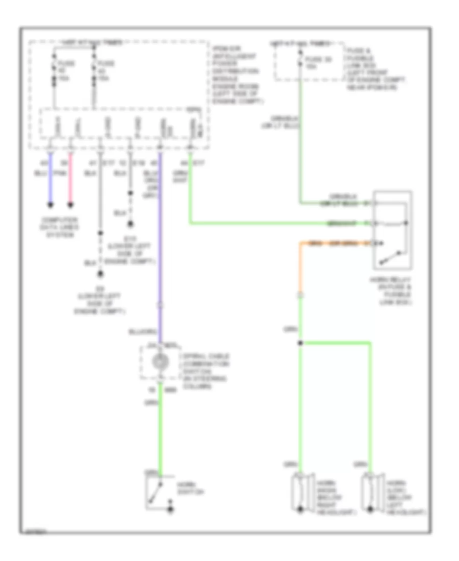
HORN Horn Wiring Diagram for Nissan Altima SE 2009 List of elements for Horn Wiring Diagram for Nissan Altima SE 2009: 27 15a Can-h Can-l Computer data lines system Cpu E15 (lower left side of engine compt) E17 E18 E9 (lower left side of engine compt) Fuse Fuse & fusible link box (left front of engine compt, near ipdm e/r) Fuse 15a Fuse 30 15a Horn (high) (below right headlight) Horn (low) (below left headlight) Horn relay (in fuse & fusible link box) Horn switch Hot at all times Ipdm e/r (intelligent power distribution module engine room) (left side of engine compt) M30 M88 P-gnd Pnk Rly horn S-gnd Spiral cable (combination switch) (in steering column) Sw horn
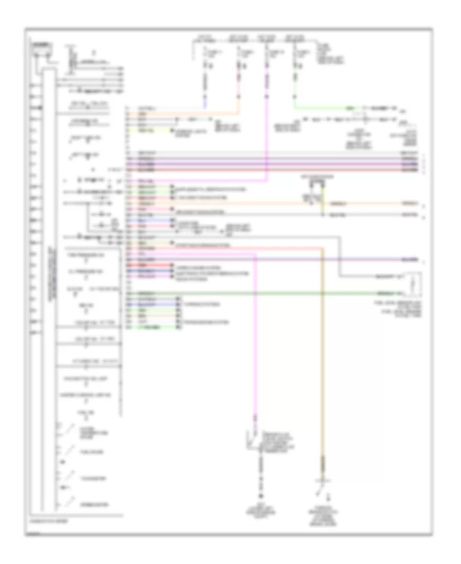
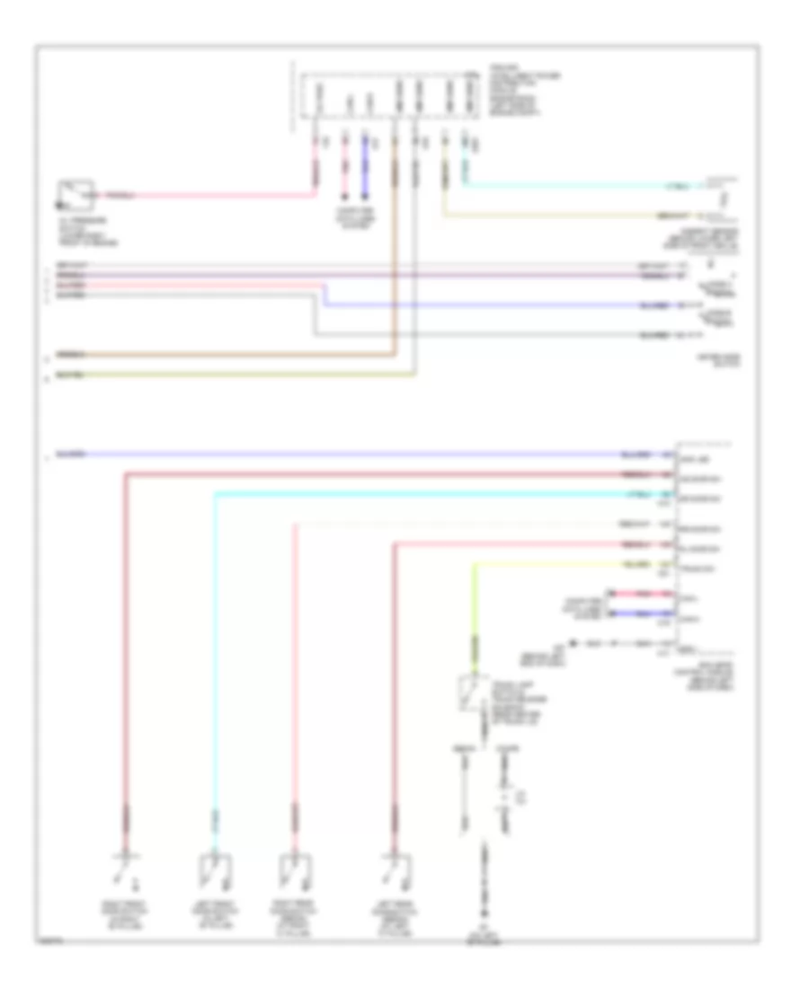
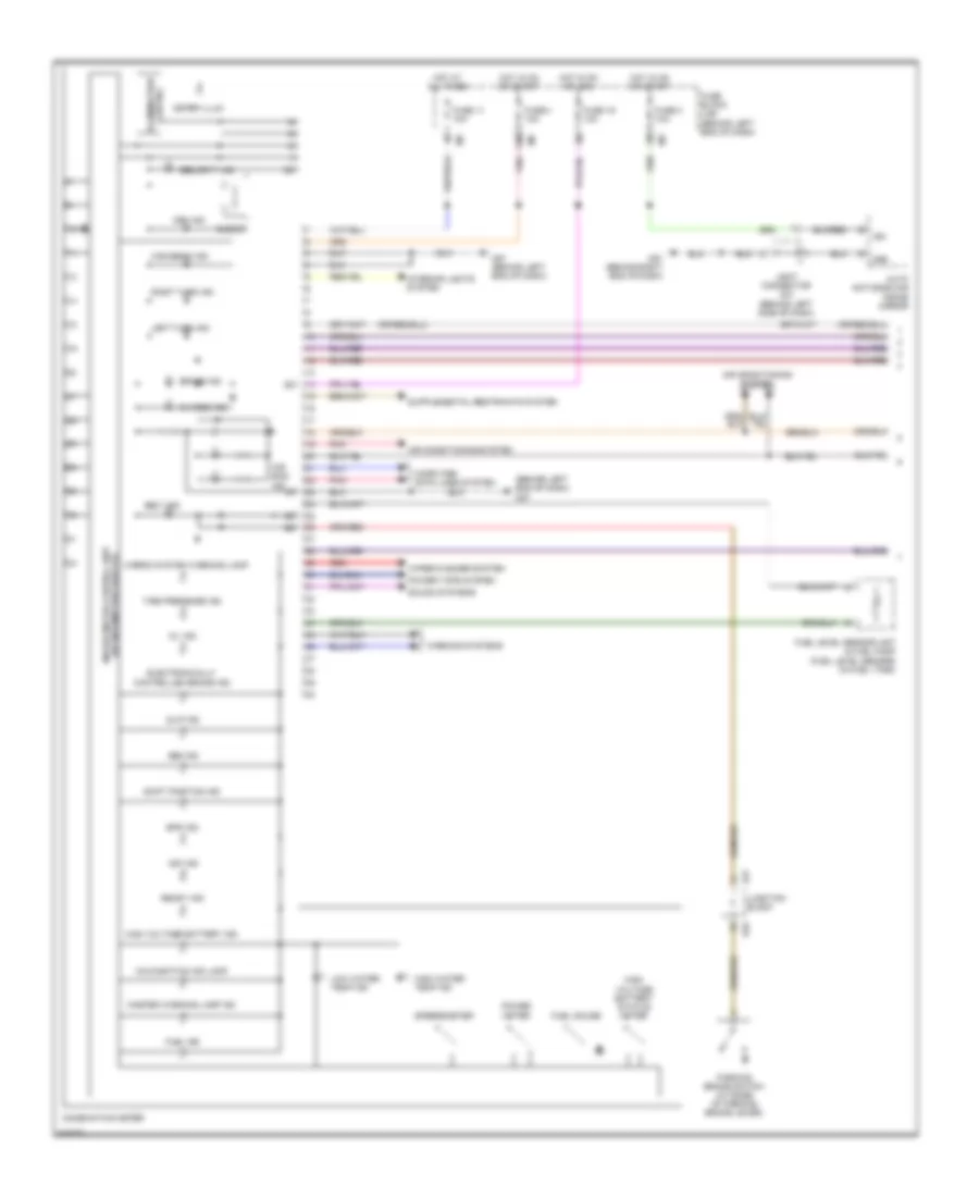
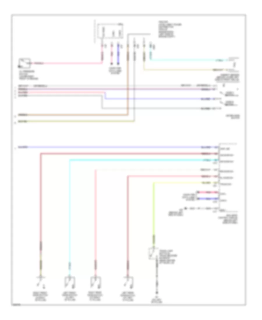
INSTRUMENT CLUSTER Instrument Cluster Wiring Diagram, Except Hybrid (1 of 2) for Nissan Altima SE 2009 List of elements for Instrument Cluster Wiring Diagram, Except Hybrid (1 of 2) for Nissan Altima SE 2009: 63 (behind left end of dash) m57 (w/ cvt) (w/ tcs or vdc) (w/ tcs) (w/ vdc) 12m Abs ind Air bag ind Air conditioning system At check ind Auto anti-dazzling inside mirror Belt ind Brake fluid level switch (on master cylinder fluid reservoir) Brake ind Buzzer Charge ind Combination meter Computer data lines system E15 (lower left side of engine compt) Electronic power steering system Fuel gauge Fuel ind Fuel level sensor unit & fuel pump (fuel level sensor) (in fuel tank) Fuse 11 10a Fuse 19 10a Fuse 3 10a Fuse 4 10a Fuse block (j/b) (behind left end of dash) Gnd High beam ind Hot at all times Hot in on or acc Hot in on or start Ign Illumination control Interior lights system Joint connector m01 (behind left side of dash) Key ind Left turn ind M57 (behind left end of dash) M61 (behind right end of dash) Malfunction ind lamp Master warning lamp ind Meter illum Oil pressure ind Parking brake switch (at base of parking brake lever) Pnk Red Right turn ind Security ind Slip ind Sound systems Speedometer Starting/charging system Tachometer Tcs off ind Tire pressure ind Transmissions system Unified meter control unit (w/ information display) Vdc off ind Warning systems Water temperature gauge Wiper/washer system Instrument Cluster Wiring Diagram, Except Hybrid (2 of 2) for Nissan Altima SE 2009 List of elements for Instrument Cluster Wiring Diagram, Except Hybrid (2 of 2) for Nissan Altima SE 2009: 39 Amb sens Ambient sensor (behind lower left side of front grille) As door sw B7 (on left "b" pillar) Bcm (body control module) (behind left side of dash) Can-h Can-l Computer data lines system Coupe Cpu Dr door sw E17 E18 E201 F10 Gnd 1 Immo led Ipdm e/r (intelligent power distribution module engine room) (left side of engine compt) J/c t01 Left front door switch (in left "b" pillar) Left rear door switch (sedan) (at left "c" pillar) M17 M18 M19 M21 M57 (behind left end of dash) Meter mode switch Mode a switch Mode b switch Oil pres Oil pressure switch (lower right front of engine) Pnk Right front door switch (in right "b" pillar) Right rear door switch (sedan) (at right "c" pillar) Rl door sw Rr door sw Sedan Trunk lamp switch & trunk release solenoid (rear center of trunk lid) Trunk sw Instrument Cluster Wiring Diagram, Hybrid (1 of 2) for Nissan Altima SE 2009 List of elements for Instrument Cluster Wiring Diagram, Hybrid (1 of 2) for Nissan Altima SE 2009: 64 (behind left end of dash) m57 12m Abs ind Air bag ind Air conditioning system Auto anti-dazzling inside mirror Belt ind Brake ind Buzzer Charge ind Combination meter Computer data lines system E47 E49 Electronically controlled brake ind Eps ind Fuel gauge Fuel ind Fuel level sensor unit & fuel pump (fuel level sensor) (in fuel tank) Fuse 11 10a Fuse 19 10a Fuse 3 10a Fuse 4 10a Fuse block (j/b) (behind left end of dash) Gnd High beam ind High voltage battery ind High voltage battery status meter High water temp ind Hot at all times Hot in on or acc Hot in on or start Hybrid system warning lamp Ign Illumination control Interior lights system Joint connector m01 (behind left side of dash) Junction block Key ind Left turn ind Low water temp ind M57 (behind left end of dash) M61 (behind right end of dash) Malfunction ind lamp Master warning lamp ind Meter illum Oil ind Parking brake switch (at base of parking brake lever) Pnk Power meter Power tops system Ready ind Red Right turn ind Security ind Shift position ind Slip ind Sound systems Speedometer Tire pressure ind Unified meter control unit (w/ information display) Vdc ind Warning systems Wiper/washer system Instrument Cluster Wiring Diagram, Hybrid (2 of 2) for Nissan Altima SE 2009 List of elements for Instrument Cluster Wiring Diagram, Hybrid (2 of 2) for Nissan Altima SE 2009: 35 Ambient sensor (behind lower left side of front grille) As door sw B7 (on left "b" pillar) Bcm (body control module) (behind left side of dash) Can-h Can-l Computer data lines system Cpu Dr door sw E17 E18 E201 F10 Gnd 1 Immo led Ipdm e/r (intelligent power distribution module engine room) (left side of engine compt) Left front door switch (in left "b" pillar) Left rear door switch (at left "c" pillar) M17 M18 M19 M21 M57 (behind left end of dash) Meter mode switch Mode a switch Mode b switch Oil pres Oil pressure switch (lower right front of engine) Pnk Right front door switch (in right "b" pillar) Right rear door switch (at right "c" pillar) Rl door sw Rr door sw Trunk lamp switch & trunk release solenoid (rear center of trunk lid) Trunk sw
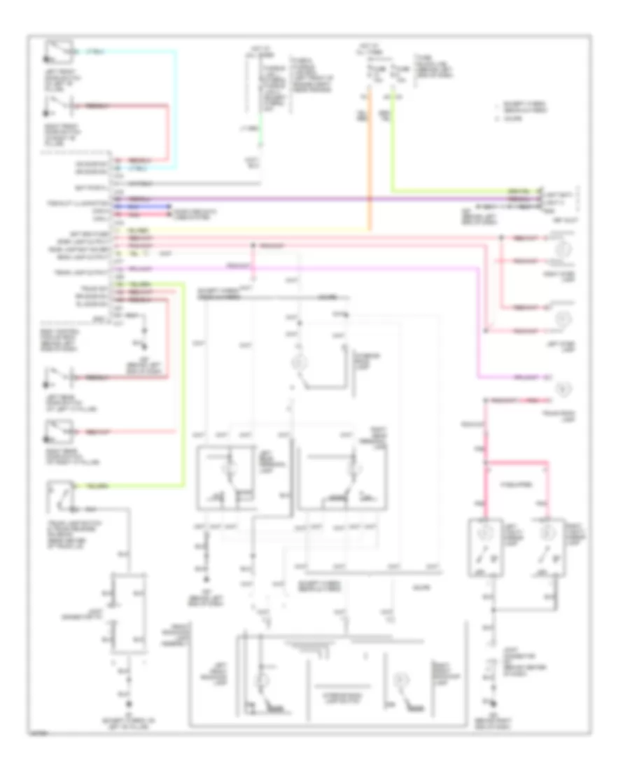
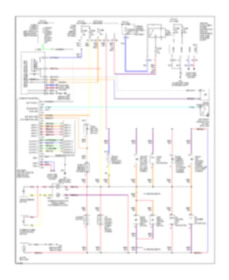
INTERIOR LIGHTS Courtesy Lamps Wiring Diagram for Nissan Altima SE 2009 List of elements for Courtesy Lamps Wiring Diagram for Nissan Altima SE 2009: 58 As door sw B7 (except hybrid: on left "b" pillar) Bat bcm fuse Bat pwr f/l Body control module (bcm) (behind left side of dash) Can-h Can-l Computer data lines system Coupe Door Dr door sw Except hybrid sedan & hybrid Fob slot illumination Front room/map lamp assembly Fuse & fusible link box (left front of engine compt, near ipdm e/r) Fuse 10a Fuse block (j/b) (behind left end of dash) Fusible link j (hybrid) fusible link h (except hybrid) 40a Gnd 1 Hot at all times If equipped Interior room lamp Interior room lamp switch Joint connector m01 (behind center of dash) Joint connector t01 Key slot Left front door switch (in left "b" pillar) Left front room/map lamp Left rear door switch (at left "c" pillar) Left rear personal lamp Left step lamp Left vanity mirror lamp Light bat+ light a gnd M16 M17 M18 M19 M20 M21 M57 (behind left end of dash) M61 (behind right end of dash) Off Pnk Right front door switch (in right "b" pillar) Right front room/map lamp Right rear door switch (at right "c" pillar) Right rear personal lamp Right step lamp Right vanity mirror lamp Rl door sw Room lamp bat saver Room lamp output Rr door sw Step lamp output Trunk lamp output Trunk lamp switch & trunk release solenoid (rear center of trunk lid) Trunk room lamp Trunk sw Instrument Illumination Wiring Diagram for Nissan Altima SE 2009 List of elements for Instrument Illumination Wiring Diagram for Nissan Altima SE 2009: 86 (combination switch) spiral cable (in steering column) (or pnk) 12m m5 7n m3 A/t device (w/ cvt) (except hybrid) ecvt device (hybrid) Ascd steering switch Audio unit (w/o navigation) Av control unit (w/ navigation) Bat bcm fuse Bat pwr f/l Bcm (body control module) (behind left side of dash) Can-h Can-l Cd changer (w/ navigation) Combination meter Combination switch Computer data lines system Cont Control Control illumination Cpu Diode 3 (behind center of dash) Door mirror remote Dr door sw E15 (lower left side of engine compt) E16 E17 E18 E6 9p Front air control (except hybrid) controller (auto amp) (hybrid) Front room/ map lamp assembly Fuse & fusible link box (left front of engine compt, near ipdm e/r) Fuse 10a Fuse 15a Fuse block (j/b) (behind left end of dash) Fusible link box (battery) (at battery) Fusible link d 60a Fusible link j (hybrid) fusible link h (except hybrid) 40a Glove box lamp Gnd 1 Hazard switch Hot at all times Hot in on or start Ill Ill+ Ill- Input 1 Input 2 Input 3 Input 4 Input 5 Ipdm e/r (intelligent power distribution module engine room) (left side of engine compt) Left front door switch (in left "b" pillar) Left front heated seat switch Low side push led M16 M17 M18 M19 M29 M30 M4 8q M57 (behind left end of dash) M61 (behind right end of dash) M88 Meter ill Meter mode switch Output 1 Output 2 Output 3 Output 4 Output 5 P-gnd Pnk Push led Push- button ignition Right front heated seat switch S-gnd Steering wheel audio control switch Switch Switch (w/ power outside mirrors) Tail Tail lamp relay Unified meter control unit (with information display) Vdc off switch (w/ vdc) tcs off switch (w/ tcs) (except hybrid) W/ heated seats
NAVIGATION Navigation Wiring Diagram, Coupe (1 of 2) for Nissan Altima SE 2009 List of elements for Navigation Wiring Diagram, Coupe (1 of 2) for Nissan Altima SE 2009: 89 (behind center of dash) (or pnk) Acc Amp on Antenna amplifier Aux gnd Aux in l Aux in r Aux jack Aux out l Aux out r Av control unit B + Back Can h Can l Cd changer Combination meter Comp in + Comp in - Computer data lines system Data gnd Down menu Down vol Enter Fr lh + Fr lh - Fr rh + Fr rh - Fuse 10a Fuse block (j/b) (behind left end of dash) Gnd Gps antenna Hot in on or acc Hot in on or start Ign Ill Ill + Ill - Ill cont Interior lights system J/c m02 M30 M46 M47 M48 M57 (behind left end of dash) M81 M88 M90 M91 Main antenna Mic + b Mic gnd Mic in + Microphone N-bus l + N-bus l - N-bus r + N-bus r - Nca Parking brake switch (at base of parking brake lever) Phone Pkb Pnk Red Req Req2 Rr lh + Rr lh - Rr rh + Rr rh - Rv cam sig Satellite antenna Sheild Shield Sig Source Speed (8p) Spiral cable (combination switch) (in steering column) Steering wheel audio control switches Strg sw gnd Strg sw sig 1 Strg sw sig 2 Unified meter control unit (w/ information display) Up menu Up vol Vcc Window antenna Navigation Wiring Diagram, Coupe (2 of 2) for Nissan Altima SE 2009 List of elements for Navigation Wiring Diagram, Coupe (2 of 2) for Nissan Altima SE 2009: 70 (at left "c" pillar) b19 (at right "c" pillar) b117 (behind left end of dash) m57 (left side of luggage compt) j/c b07 (on left "b" pillar) b7 Acc Amp on B + B121 B122 B7 (on left "b" pillar) Bat Bose speaker amplifier (under rear parcel shelf) Camera + Camera - Camera on Center speaker Comp + Comp - Computer data lines system Control 1 Ddl (k-line) Exterior lights system Fr door rh + out Fr door rh - out Fr lh + in Fr lh - in Fr rh + in Fr rh - in Fr twdr lh + out Fr twdr lh - out Fr twdr rh + out Fr twdr rh - out Fuse & fusible link box (left front of engine compt, near ipdm e/r) Fuse 15a Gnd Hot at all times Inst ctr twdr + out Inst ctr twdr - out J/c b05 (in trunk lid) J/c m02 (behind center of dash) Left door speaker Left front tweeter Left rear subwoofer Left rear tweeter Lh woofer + out Lh woofer - out Nca Pnk Rear view camera Rear view camera control unit (left side of luggage compt) Red Rev Rh woofer + out Rh woofer - out Right door speaker Right front tweeter Right rear subwoofer Right rear tweeter Rr lh + in Rr lh - in Rr rh + in Rr rh - in Rr twdr lh + out Sheild Shield Twtr rr lh + out Twtr rr lh - out Twtr rr rh + out Twtr rr rh - out Navigation Wiring Diagram, Sedan (1 of 2) for Nissan Altima SE 2009 List of elements for Navigation Wiring Diagram, Sedan (1 of 2) for Nissan Altima SE 2009: 93 (or shield) Acc Amp on Antenna amplifier Aux gnd Aux in l Aux in r Aux jack Aux out l Aux out r Av control unit B + Back Can h Cd changer Combination meter Comp in + Comp in - Computer data lines system Data gnd Down menu Down vol E47 E49 Enter Except hybrid Fr lh + Fr lh - Fr rh + Fr rh - Fuse 10a Fuse block (j/b) (behind left end of dash) Gnd Gps antenna Hot in on or acc Hot in on or start Hybrid Ign Ill Ill + Ill - Ill cont Interior lights system J/c m02 (behind center of dash) Junction block M30 M46 M47 M48 M57 (behind left end of dash) M81 M88 M90 M91 Main antenna Mic + b Mic gnd Mic in + Microphone N-bus l + N-bus l - N-bus r + N-bus r - Nca Parking brake switch (at base of parking brake lever) Phone Pkb Pnk Red Req Req2 Roof antenna (audio) Rr lh + Rr lh - Rr rh + Rr rh - Rv cam sig Satellite antenna Shield Sig Source Speed (8p) Spiral cable (combination switch) (in steering column) Steering wheel audio control switches Strg sw gnd Strg sw sig 1 Strg sw sig 2 Unified meter control unit (w/ information display) Up menu Up vol V-can l Vcc Window antenna Navigation Wiring Diagram, Sedan (2 of 2) for Nissan Altima SE 2009 List of elements for Navigation Wiring Diagram, Sedan (2 of 2) for Nissan Altima SE 2009: 66 (at right "c" pillar) b117 (left side of luggage compt) j/c b07 (or sheild) (or shield) Acc Amp on B + B121 B122 B7 (on left "b" pillar) Bat Bose speaker amplifier (under rear parcel shelf) Camera + Camera - Camera on Center speaker Comp + Comp - Computer data lines system Control 1 Ddl (k-line) Exterior lights system Fr door rh + out Fr door rh - out Fr lh + in Fr lh - in Fr rh + in Fr rh - in Fr twdr lh + out Fr twdr lh - out Fr twdr rh + out Fr twdr rh - out Fuse & fusible link box (left front of engine compt, near ipdm e/r) Fuse 15a Gnd Hot at all times Inst ctr twdr + out Inst ctr twdr - out J/c b09 (left front of luggage compt) Left front door speaker Left rear door speaker Left rear subwoofer Left tweeter Lh woofer + out Lh woofer - out Nca Pnk Rear view camera (left rear body) Rear view camera control unit (left side of luggage compt) Red Rev Rh woofer + out Rh woofer - out Right front door speaker Right rear door speaker Right rear subwoofer Right tweeter Rr door lh + out Rr door lh - out Rr door rh + out Rr door rh - out Rr lh + in Rr lh - in Rr rh + in Rr rh - in Rr twdr lh + out
POWER DISTRIBUTION Power Distribution Wiring Diagram, Except Hybrid (1 of 3) for Nissan Altima SE 2009 List of elements for Power Distribution Wiring Diagram, Except Hybrid (1 of 3) for Nissan Altima SE 2009: 52 (at battery) fusible link box (battery) (left front of engine compt, near ipdm e/r) fuse & fusible link box (left side of engine compt) intelligent power distribution module engine room (ipdm e/r) Anti-lock brakes system Battery Cpu E16 E18 E201 Ecm relay Engine controls system Exterior lights system F10 Front fog lamp relay Fuse (canada) 10a Fuse 10a Fuse 10a (m/t) Fuse 15a Fuse 30a Fusible link a 250a Fusible link b 80a Fusible link c 100a Fusible link d 60a Fusible link e 100a Fusible link f 50a Fusible link g 30a Fusible link h 40a Fusible link i 40a Fusible link k 40a Fusible link l 40a Fusible link m 40a Headlamp high relay Headlamp low relay Headlights system Headlights, interior lights & exterior lights systems Horns, anti-theft & door locks systems Joint connector e01 Red Sound & navigation systems Starter relay Starting/ charging system Starting/ charging, anti-theft & door locks systems Tail lamp relay Throttle control motor relay To bcm (diagram 3 of 3) To front wiper relay (diagram 2 of 3) To fuse 40 (diagram 2 of 3) To fuse block (j/b) fuse 5 (diagram 2 of 3) To ignition relay 2 (diagram 3 of 3) W/ bose audio system W/ vdc W/o vdc Power Distribution Wiring Diagram, Except Hybrid (2 of 3) for Nissan Altima SE 2009 List of elements for Power Distribution Wiring Diagram, Except Hybrid (2 of 3) for Nissan Altima SE 2009: 44 (left side of engine compt) intelligent power distribution module engine room (ipdm e/r) 11p 12p 1s e7 5n m3 7m m5 7q m4 A/c relay Accessory relay Air conditioning system Air conditioning, sound, mirrors, door locks, instrument cluster, anti-theft, power tops & navigation systems Anti-lock brakes, transmissions, engine controls & exterior lights systems Anti-theft & door locks systems Cooling fan relay 1 Cooling fans system Cpu Door locks & anti-theft systems E15 (lower left side of engine compt) E17 E18 F10 From fuse 43 (diagram 1 of 3) From fuse 55 (diagram 1 of 3) From fusible link box (battery) fusible link c (diagram 1 of 3) Front console power socket Front power socket Front wiper high relay Front wiper relay Fuse 10a Fuse 15a Fuse block (j/b) (behind left end of dash) Headlights, exterior lights, interior lights, door locks, anti-theft, instrument cluster & warning system Ignition relay 1 M57 (behind left end of dash) M61 (behind right end of dash) Steering column lock relay To bcm (diagram 3 of 3) To fuel pump relay (diagram 3 of 3) To fuse 10 (diagram 3 of 3) To fuse 32 (diagram 3 of 3) To push button ignition switch (diagram 3 of 3) Transmissions system Transmissions, engine controls, air conditioning & mirrors systems Wiper/washer system Power Distribution Wiring Diagram, Except Hybrid (3 of 3) for Nissan Altima SE 2009 List of elements for Power Distribution Wiring Diagram, Except Hybrid (3 of 3) for Nissan Altima SE 2009: 56 (behind right end of dash) m61 (left side of engine compt) intelligent power distribution module engine room (ipdm e/r) 10m 10t b4 11m 11t 12m m5 2n m3 3n m3 4p e6 7m m5 9m m5 Acc ind Air conditioning system Air conditioning, sound, navigation, instrument cluster, transmissions, electronic power steering, mirrors, defogger & warning systems Anti-lock brakes system Bcm (body control module) Cpu Defogger system Door locks, anti-theft & starting/charging systems E18 E200 Engine controls system F10 From cpu f (diagram 2 of 3) From fuse & fusible link box h fusible link j (diagram 1 of 3) From fuse 11 d (diagram 2 of 3) From fuse block (j/b) e accessory relay (diagram 2 of 3) From fuse block i (j/b) fuse 9 (diagram 2 of 3) From g fuse 41 (diagram 2 of 3) From joint connector e01 (diagram 1 of 3) Front blower motor relay Fuel pump relay Fuse 10a Fuse 15a Fuse 20a Fuse block (j/b) (behind left end of dash) Ignition relay 2 Intelligent power distribution module engine room (ipdm e/r) (left side of engine compt) Interior lights system Lock ind M16 M17 M18 M19 M57 (behind left end of dash) On ind Pnk Push button ignition switch Push switch Rear window defogger relay Red Seats system Shift interlock system Transmissions system Wiper/washer system Power Distribution Wiring Diagram, Hybrid (1 of 3) for Nissan Altima SE 2009 List of elements for Power Distribution Wiring Diagram, Hybrid (1 of 3) for Nissan Altima SE 2009: 53 (left front of engine compt, near ipdm e/r) fuse & fusible link box (left side of engine compt) intelligent power distribution module engine room (ipdm e/r) Anti- lock brakes system Anti-lock brakes system Battery Bcm (diagram 3 of 3) Cpu E16 E18 E201 E9 (lower left side of engine compt) Ecm relay Electronic power steering system Engine controls system Exterior lights system F10 From fuse & fusible link box fusible link f (diagram 1 of 3) From fusible a link d (diagram 1 of 3) Front fog lamp relay Fuse (canada) 10a Fuse 10a Fuse 15a Fuse 30a Fusible link a 140a Fusible link b 100a Fusible link b 120a Fusible link box (battery) (at battery) Fusible link c 100a Fusible link d 120a Fusible link e 80a Fusible link f 60a Fusible link g 50a Fusible link h 50a Fusible link i 30a Fusible link j 40a Fusible link m 40a Fusible link o 50a Headlamp high relay Headlamp low relay Headlights system Headlights, interior lights & exterior lights systems Horns & anti-theft systems Igct relay Red Sound systems Tail lamp relay Throttle control motor relay To front wiper relay (diagram 2 of 3) To fuse 40 (diagram 2 of 3) To fuse block (j/b) fuse 5 (diagram 2 of 3) To fusible link e (diagram 1 of 3) To ignition relay 2 (diagram 3 of 3) To intelligent power distribution module engine room (ipdm e/r) fuse 54 (diagram 1 of 3) Power Distribution Wiring Diagram, Hybrid (2 of 3) for Nissan Altima SE 2009 List of elements for Power Distribution Wiring Diagram, Hybrid (2 of 3) for Nissan Altima SE 2009: 41 (left side of engine compt) intelligent power distribution module engine room (ipdm e/r) 11p 1s e7 5n m3 7m m5 7q m4 Accessory relay Air conditioning system Air conditioning, engine controls, door locks, anti-theft & navigation systems Air conditioning, sound, mirrors, door locks, instrument cluster, anti-theft & power tops systems Anti-lock brakes, door locks, anti-theft, exterior lights & engine controls systems Anti-theft & door locks systems Cpu E15 (lower left side of engine compt) E17 E18 E9 (lower left side of engine compt) Electronic steering column lock relay F10 From fuse 43 (diagram 1 of 3) From fuse 55 (diagram 1 of 3) From fusible link box (battery) fusible link b (diagram 1 of 3) Front console power socket Front power socket Front wiper high relay Front wiper relay Fuse 10a Fuse 15a Fuse block (j/b) (behind left end of dash) Headlights, interior lights, door locks, instrument cluster, anti-theft, warning & exterior lights systems Heater pump relay Ignition relay 1 M57 (behind left end of dash) M61 (behind right end of dash) Red To bcm (diagram 3 of 3) To fuel pump relay (diagram 3 of 3) To fuse 10 (diagram 3 of 3) To fuse 32 (diagram 3 of 3) To push button ignition switch (diagram 3 of 3) Wiper/washer system Power Distribution Wiring Diagram, Hybrid (3 of 3) for Nissan Altima SE 2009 List of elements for Power Distribution Wiring Diagram, Hybrid (3 of 3) for Nissan Altima SE 2009: 53 (behind right end of dash) m61 10m 10t b4 11m 11t 12m m5 2n m3 3n m3 4p e6 7m m5 9m m5 Acc ind Air conditioning system Air conditioning, sound, mirrors, defogger, warning, engine controls, instrument cluster & shift interlock systems Anti-lock brakes system Bcm (body control module) Cpu Defogger system E18 E200 Electronic power steering & engine controls systems Engine controls system F10 From cpu l (diagram 2 of 3) From fuse & fusible link box b fusible link j (diagram 1 of 3) From fuse & fusible link box fusible link m (diagram 1 of 3) From fuse 11 f (diagram 2 of 3) From fuse block (j/b) h accessory relay (diagram 2 of 3) From fuse block i (j/b) fuse 9 (diagram 2 of 3) From k ignition 1 relay (diagram 2 of 3) Front blower motor relay Fuel pump relay Fuse 10a Fuse 15a Fuse 20a Fuse block (j/b) (behind left end of dash) Ignition relay 2 Intelligent power distribution module engine room (ipdm e/r) (left side of engine compt) Interior lights system Lock ind M16 M17 M18 M19 M57 (behind left end of dash) On ind Push button ignition switch Push switch Rear window defogger Red Relay Seats system Wiper/washer system
POWER DOOR LOCKS Power Door Locks Wiring Diagram, with Intelligent Key Unit (2 of 4) for Nissan Altima SE 2009 List of elements for Power Door Locks Wiring Diagram, with Intelligent Key Unit (2 of 4) for Nissan Altima SE 2009: 32 (at left "c" pillar) b19 (behind left end of dash) m57 (behind right end of dash) m61 Ant+ Ant- Cpu E15 (lower left side of engine compt) E17 E18 F10 Front console antenna Fuse 10a Horns system Hot at all times Ignition relay-1 Ipdm e/r (intelligent power distribution module engine room) (left side of engine compt) J/c b05 (in trunk lid) J/c m02 (behind center of dash) Left front outside handle Nca Outside key antenna Pnk Rear parcel shelf antenna (under center of rear parcel shelf) Red Request switch Right front outside handle Starter control relay (except hybrid) Starter relay (except hybrid) Starting/ charging system Steering lock relay (except hybrid sedan) electronic steering column lock relay (hybrid & except hybrid coupe) W/ cvt W/ left front power window anti-pinch system Power Door Locks Wiring Diagram, with Intelligent Key Unit (3 of 4) for Nissan Altima SE 2009 List of elements for Power Door Locks Wiring Diagram, with Intelligent Key Unit (3 of 4) for Nissan Altima SE 2009: 28 (at left "c" pillar) b19 (left front of engine compt) (w/ cvt & 3.5l) tcm (m/t) clutch interlock switch (m/t) j/c e05 (w/ cvt & 2.5l: on transmission) (m/t: left rear of transaxle) park/neutral position (pnp) switch B7 (on left "b" pillar) E46 E50 Except hybrid coupe F16 Fuse & fusible link box (left front of engine compt, near ipdm e/r) Fuse 10a Hot at all times Hybrid & except hybrid sedan J/c t01 Junction block Left front door switch (in left "b" pillar) Left rear door switch (except hybrid sedan & hybrid) (at left "c" pillar) M/t Red Right front door switch (in right "b" pillar) Right rear door switch (except hybrid sedan & hybrid) (at right "c" pillar) St rly Trunk lamp switch & trunk release solenoid (rear center of trunk lid) Trunk opener request switch W/ cvt W/ cvt & 2.5l W/ left front power window anti-pinch system Power Door Locks Wiring Diagram, with Intelligent Key Unit (4 of 4) for Nissan Altima SE 2009 List of elements for Power Door Locks Wiring Diagram, with Intelligent Key Unit (4 of 4) for Nissan Altima SE 2009: 49 (behind left end of dash) m57 1n m3 Acc ind Actuator Between full stroke & n Buzzer Care switch 1 Clock Combination meter Computer data lines system Cpu Data Door unlock sensor Except hybrid coupe Full stroke Fuse 10a Fuse block (j/b) (behind left end of dash) Gnd Hot at all times Hybrid & except hybrid sedan Key cylinder switch Key ind Key slot Left front door lock assembly (rear of left front door) Left rear door lock actuator (except hybrid sedan & hybrid) (rear of left rear door) Light a Light bat+ Lock Lock ind Lock switch M57 (behind left end of dash) M61 (behind right end of dash) Main power window & door lock/unlock switch (w/ left & right front power window anti-pinch system) Main power window & door lock/unlock switch (w/ left front power window anti-pinch system) On ind Pnk Push button ignition switch Push switch Red Right front door lock actuator (rear of right front door) Right power window & door lock/unlock switch (w/ left & right front power window anti-pinch system) Right power window & door lock/unlock switch (w/ left front power window anti-pinch system) Right rear door lock actuator (except hybrid sedan & hybrid) (rear of right rear door) Security ind Un lock Unified meter control unit (w/ information display) Unlock Unlock switch W/ left front power window anti-pinch system Power Door Locks Wiring Diagram, without Intelligent Key Unit (1 of 3) for Nissan Altima SE 2009 List of elements for Power Door Locks Wiring Diagram, without Intelligent Key Unit (1 of 3) for Nissan Altima SE 2009: 92 (behind left end of dash) m57 (behind right end of dash) m61 (on steering column) electronic steering column lock 12v 2p e6 7n m3 Acd led Ant+ Ant- As door switch At device out Bat bcm fuse Bat power f/l Bcm (body control module) (behind left side of dash) Buzzer Can-h Can-l Cdl as Cdl common Cdl dr/fl Cdl rr rl back Central lock switch Central unlock switch Computer data lines system Cvt device (if equipped) Door key/c lock switch Door key/c unlock switch Door lock status Dr door switch E6 11p Eng start switch Exterior lights system Fl flasher Fob in switch 1 Fob reader clock Fob reader data Fob slot illumination Fr flasher Fuse & fusible link box (left front of engine compt, near ipdm e/r) Fuse 10a Fuse block (j/b) (behind left end of dash) Fusible link j (hybrid) fusible link h (except hybrid) 40a Gnd Gnd rf2 a/l Gnd1 Hazard switch Hot at all times Ign on led Immo led Instrument panel antenna (under center of dash) Interior lights system Left rear door switch (except hybrid sedan & hybrid) (at left "c" pillar) M16 M17 M18 M19 M21 M4 3q M4 9q Outside warning buzzer Pnk Pw k-line Red Remote keyless entry receiver (if equipped) (behind right end of dash) Rf1 tuner signal Right rear door switch (except hybrid sedan & hybrid) (at right "c" pillar) Rl door switch Room ant 1 a Room ant 1 b Room ant 2 a Room ant 2 b Room lamp bat saver Room lamp output Rr door switch S/l 12v cpu S/l 12v mechanical S/l com S/l condition 1 S/l condition 2 S/l k-line S/l lock led Shift n/p Shift p Signal St cont usm Stop lamp high switch Stop lamp low switch Stop light switch (above brake pedal, on bracket) Trunk ant 1 a Trunk ant 1 b Trunk switch W/ left front power window anti-pinch system Power Door Locks Wiring Diagram, without Intelligent Key Unit (2 of 3) for Nissan Altima SE 2009 List of elements for Power Door Locks Wiring Diagram, without Intelligent Key Unit (2 of 3) for Nissan Altima SE 2009: 31 Ant+ Ant- B7 (on left "b" pillar) Cpu E15 (lower left side of engine compt) E17 E18 E46 E50 Except hybrid coupe F10 Front console antenna Fuse 10a Horns system Hot at all times Hybrid & except hybrid sedan Ignition relay-1 Ipdm e/r (intelligent power distribution module engine room) (left side of engine compt) J/c t01 Junction block Left front door switch (in left "b" pillar) Park/neutral position (pnp) switch (w/ cvt & 2.5l: on transmission) (m/t: left rear of transaxle) Rear parcel shelf antenna (under center of rear parcel shelf) Red Right front door switch (in right "b" pillar) Starter control relay (except hybrid) Starter relay (except hybrid) Starting/ charging system Steering lock relay Trunk light switch & trunk release solenoid (rear center of trunk lid) W/ left front power window anti-pinch system Power Door Locks Wiring Diagram, without Intelligent Key Unit (3 of 3) for Nissan Altima SE 2009 List of elements for Power Door Locks Wiring Diagram, without Intelligent Key Unit (3 of 3) for Nissan Altima SE 2009: 51 (behind left end of dash) m57 1n m3 Acc ind Actuator Between full stroke & n Buzzer Care switch 1 Clock Combination meter Computer data lines system Cpu Data Door unlock sensor Except hybrid Except hybrid coupe Full stroke Fuse 10a Fuse block (j/b) (behind left end of dash) Gnd Hot at all times Hybrid Key cylinder switch Key ind Key slot Left front door lock assembly (rear of left front door) Left rear door lock actuator (except hybrid sedan & hybrid) (rear of left rear door) Light a Light bat+ Lock Lock ind Lock switch M57 (behind left end of dash) M61 (behind right end of dash) Main power window & door lock/unlock switch (w/ left & right front power window anti-pinch system) Main power window & door lock/unlock switch (w/ left front power window anti-pinch system) On ind Pnk Push button ignition switch Push switch Red Right front door lock actuator (rear of right front door) Right power window & door lock/unlock switch (w/ left & right front power window anti-pinch system) Right power window & door lock/unlock switch (w/ left front power window anti-pinch system) Right rear door lock actuator (except hybrid sedan & hybrid) (rear of right rear door) Security ind Sedan & hybrid Un lock Unified meter control unit (w/ information display) Unlock Unlock switch W/ left front power window anti-pinch system
POWER MIRRORS Auto Anti-dazzling Inside Mirror Wiring Diagram for Nissan Altima SE 2009 List of elements for Auto Anti-dazzling Inside Mirror Wiring Diagram for Nissan Altima SE 2009: 10 Auto anti-dazzling inside mirror Bat+ Fuse 10a Fuse block (j/b) (behind left end of dash) Gnd Hot at all times Hot in on or start Ign Joint connector m01 (behind left side of dash) M61 (behind right end of dash) Power Mirrors Wiring Diagram for Nissan Altima SE 2009 List of elements for Power Mirrors Wiring Diagram for Nissan Altima SE 2009: 14 Changeover switch Defogger system Door mirror remote control switch Exterior lights system Fuse 19 10a Fuse block (j/b) (behind left end of dash) Hot in acc or on Illumination Interior lights system Left door mirror M57 (behind left end of dash) Mirror switch Off Right door mirror
POWER SEATS Driver Power Seat Wiring Diagram for Nissan Altima SE 2009 List of elements for Driver Power Seat Wiring Diagram for Nissan Altima SE 2009: 27 (behind left end of dash) m57 (on left "b" pillar) b7 B7 (on left "b" pillar) Bat Body control module (bcm) (behind left side of dash) Bwd Down Front lifting motor Front lifting switch Fuse & fusible link box (left front of engine compt, near ipdm e/r) Fusible link j (hybrid) fusible link h (except hybrid) 40a Fwd Gnd1 Hot at all times Lumbar support motor Lumbar support switch (if equipped) M16 M17 P/w Power seat switch Rear lifting motor Rear lifting switch Reclining motor Reclining switch Red Sliding motor Sliding switch Heated Seats Wiring Diagram for Nissan Altima SE 2009 List of elements for Heated Seats Wiring Diagram for Nissan Altima SE 2009: 13 B117 (at right "c" pillar) B7 (on left "b" pillar) Fuse 20a Fuse block (j/b) (behind left end of dash) Hot in on or start Illumination Interior lights system Joint connector m01 (behind left side of dash) Left front heated seat switch Left front heater seat M61 (behind right end of dash) Right front heated seat switch Right front heater seat
POWER TOP/SUNROOF Power Top/Sunroof Wiring Diagram for Nissan Altima SE 2009 List of elements for Power Top/Sunroof Wiring Diagram for Nissan Altima SE 2009: 36 (except hybrid) (hybrid) (w/ information display) unified meter control unit + ign Acc f/b As door sw Bat bcm fuse Bat pwr f/l Bcm (body control module) (behind left side of dash) Close t up Combination meter Dn/ open Dr door sw Fuse & fusible link box (left front of engine compt, near ipdm e/r) Fuse 10a Fuse block (j/b) (behind left end of dash) Fusible link i fusible link j 40a Gnd Gnd1 Hot at all times Hot in on or acc Left front door switch (in left "b" pillar) M16 M17 M18 M57 (behind left end of dash) Open t down Pwr sup (bat) Pwr sup (rap) Red Right front door switch (in right "b" pillar) Spd (2p) Speed (2p) Sunroof motor assembly (hybrid: front center of roof) (except hybrid: top center of headliner) Sunroof switch Up/ close
POWER WINDOWS Power Windows Wiring Diagram, Coupe with Driver & Passenger Side Anti-Pinch System for Nissan Altima SE 2009 List of elements for Power Windows Wiring Diagram, Coupe with Driver & Passenger Side Anti-Pinch System for Nissan Altima SE 2009: 50 (behind right end of dash) m61 7n m3 As door switch As down As up Bat Bat bcm fuse Bat power f/l Batt Bcm (body control module) (behind left side of dash) Between full stroke & n Com Cpu Down Dr door switch Encoder Encoder gnd Encoder power Encoder sig1 Encoder sig2 Full stroke Fuse & fusible link box (left front of engine compt, near ipdm e/r) Fuse 10a Fuse block (j/b) (behind left end of dash) Fusible link h 40a Gnd Gnd1 Hot at all times Ign Left door lock assembly (key cylinder switch) Left door switch Left power window motor Lock Lock switch M16 M17 M18 M57 (behind left end of dash) Main power window & door lock/unlock switch Power Power window- Pw k-line Right door switch Right power window & door lock/unlock switch Right power window motor Rr up Sig1 Sig2 Unlock Unlock switch Power Windows Wiring Diagram, Coupe with Driver Side Anti-Pinch System for Nissan Altima SE 2009 List of elements for Power Windows Wiring Diagram, Coupe with Driver Side Anti-Pinch System for Nissan Altima SE 2009: 45 As door switch As down As up Bat Bat bcm fuse Bat power f/l Bcm (body control module) (behind left side of dash) Central lock switch Central unlock switch Cpu D n Dr door switch Dr down Dr up Encoder Encoder gnd Encoder power Encoder sig1 Encoder sig2 Fuse & fusible link box (left front of engine compt, near ipdm e/r) Fuse 10a Fuse block (j/b) (behind left end of dash) Fusible link h 40a Gnd Gnd1 Hot at all times Ign Illumination Left door switch (in left "b" pillar) Left power window motor Lock Lock switch M16 M17 M18 M57 (behind left end of dash) M61 (behind right end of dash) Main power window & door lock/unlock switch Power window- Right door switch (in right "b" pillar) Right front Right power window & door lock/unlock switch Right power window motor Un lock Unlock Power Windows Wiring Diagram, Sedan with Driver & Passenger Side Anti-Pinch System for Nissan Altima SE 2009 List of elements for Power Windows Wiring Diagram, Sedan with Driver & Passenger Side Anti-Pinch System for Nissan Altima SE 2009: 64 (at right "c" pillar) b117 (behind left side of dash) bcm (body control module) (on left "b" pillar) b7 7n m3 As door switch As down As up Bat Bat bcm fuse Bat power f/l Batt Between full stroke & n Com Cpu Down Dr door switch Encoder Encoder gnd Encoder power Encoder sig1 Encoder sig2 Full stroke Fuse & fusible link box (left front of engine compt, near ipdm e/r) Fuse 10a Fuse block (j/b) (behind left end of dash) Fusible link j (hybrid) fusible link h (except hybrid) 40a Gnd Gnd1 Hot at all times Ign Illumination Left front door lock assembly (rear of left front door) Left front door switch (in left "b" pillar) Left front power window motor (center of left front door) Left rear Left rear power window motor (center of left rear door) Left rear power window switch Lock Lock d Lock switch M16 M17 M18 M57 (behind left end of dash) M61 (behind right end of dash) Main power window & door lock/unlock switch Power Power window- Pw k-line Right front door switch (in right "b" pillar) Right front power window motor (center of right front door) Right power window & door lock/unlock switch Right rear Right rear power window motor (center of right rear door) Right rear power window switch Rl down Rl up Rr down Rr up Sig1 Sig2 Un lock Unlock Unlock switch Power Windows Wiring Diagram, Sedan with Driver Side Anti-Pinch System for Nissan Altima SE 2009 List of elements for Power Windows Wiring Diagram, Sedan with Driver Side Anti-Pinch System for Nissan Altima SE 2009: 58 (at right "c" pillar) b117 (behind left end of dash) m57 (behind left side of dash) bcm (body control module) (behind right end of dash) m61 (on left "b" pillar) b7 As door switch As down As up Bat Bat bcm fuse Bat power f/l Central lock switch Central unlock switch Cpu D n Dr door switch Dr down Dr up Encoder Encoder gnd Encoder power Encoder sig1 Encoder sig2 Fuse & fusible link box (left front of engine compt, near ipdm e/r) Fuse 10a Fuse block (j/b) (behind left end of dash) Fusible link j (hybrid) fusible link h (except hybrid) 40a Gnd Gnd1 Hot at all times Ign Illumination Left front door switch (in left "b" pillar) Left front power window motor (center of left front door) Left rear Left rear power window motor (center of left rear door) Left rear power window switch Lock Lock switch M16 M17 M18 M57 (behind left end of dash) Main power window & door lock/unlock switch Power window- Right front Right front door switch (in right "b" pillar) Right front power window motor (center of right front door) Right power window & door lock/unlock switch Right rear Right rear power window motor (center of right rear door) Right rear power window switch Rl down Rl up Rr down Rr up Un lock Unlock
RADIO Base Radio Wiring Diagram, Coupe for Nissan Altima SE 2009 List of elements for Base Radio Wiring Diagram, Coupe for Nissan Altima SE 2009: 73 (or red) Acc Antenna amplifier Antenna signal Audio unit B57 B58 Bat Dat earth Data Earth Earth (sig) Ec1 (sat-combi) Fr sp lh (+) Fr sp lh (-) Fr sp rh (+) Fr sp rh (-) Fuse & fusible link box (left front of engine compt, near ipdm e/r) Fuse 10a Fuse 15a Fuse block (j/b) (behind left end of dash) Hot at all times Hot in on or acc Ill cont out Interior lights system Left door speaker Left front tweeter Left rear speaker M3 5n M30 M43 M45 M81 M88 Main antenna Nca Pnk Red Rfq1 (sat to combi) Right door speaker Right front tweeter Right rear speaker Rr sp lh (+) Rr sp lh (-) Rr sp rh (+) Rr sp rh (-) Rx (sat to combi) Rxd (combi-sat) Sat lch (+) Sat lch (-) Sat lh input (+) Sat lh input (-) Sat rch (+) Sat rch (-) Sat rh input (+) Sat rh input (-) Satellite antenna Satellite radio tuner (if equipped) (under rear parcel shelf) Seek down Seek up Shield Source Spiral cable (combination switch) (in steering column) Steering wheel audio control switches Strg sw a Strg sw b Strg sw gnd Tail/ill rly Tx (combi to sat) Txd (sat-combi) Vol down Vol up Window antenna Base Radio Wiring Diagram, Sedan for Nissan Altima SE 2009 List of elements for Base Radio Wiring Diagram, Sedan for Nissan Altima SE 2009: 71 5n m3 Acc Antenna amplifier Antenna signal Audio unit B123 B129 B133 Bat Ec1 (sat-combi) Except hybrid Fr sp lh (+) Fr sp lh (-) Fr sp rh (+) Fr sp rh (-) Fuse & fusible link box (left front of engine compt, near ipdm e/r) Fuse 10a Fuse 15a Fuse block (j/b) (behind left end of dash) Hot at all times Hot in on or acc Hybrid Ill cont out Interior lights system Left front door speaker Left rear speaker Left tweeter M30 M43 M45 M81 M88 Main antenna Nca Pnk Red Rfq1 (sat to combi) Right front door speaker Right rear speaker Right tweeter Roof antenna (audio) Rr sp lh (+) Rr sp lh (-) Rr sp rh (+) Rr sp rh (-) Rx (sat to combi) Rxd (combi-sat) Sat lch (+) Sat lch (-) Sat lh input (+) Sat lh input (-) Sat rch (+) Sat rch (-) Sat rh input (+) Sat rh input (-) Satellite antenna Satellite radio tuner (if equipped) (under rear parcel shelf) Seek down Seek up Source Spiral cable (combination switch) (in steering column) Steering wheel audio control switches Strg sw a Strg sw b Strg sw gnd Tail/ill rly Tx (combi to sat) Txd (sat-combi) Vol down Vol up Window antenna Bose Radio Wiring Diagram, Coupe with Navigation (1 of 2) for Nissan Altima SE 2009 List of elements for Bose Radio Wiring Diagram, Coupe with Navigation (1 of 2) for Nissan Altima SE 2009: 89 (behind center of dash) (or pnk) Acc Amp on Antenna amplifier Aux gnd Aux in l Aux in r Aux jack Aux out l Aux out r Av control unit B + Back Can h Can l Cd changer Combination meter Comp in + Comp in - Computer data lines system Data gnd Down menu Down vol Enter Fr lh + Fr lh - Fr rh + Fr rh - Fuse 10a Fuse block (j/b) (behind left end of dash) Gnd Gps antenna Hot in on or acc Hot in on or start Ign Ill Ill + Ill - Ill cont Interior lights system J/c m02 M30 M46 M47 M48 M57 (behind left end of dash) M81 M88 M90 M91 Main antenna Mic + b Mic gnd Mic in + Microphone N-bus l + N-bus l - N-bus r + N-bus r - Nca Parking brake switch (at base of parking brake lever) Phone Pkb Pnk Red Req Req2 Rr lh + Rr lh - Rr rh + Rr rh - Rv cam sig Satellite antenna Sheild Shield Sig Source Speed (8p) Spiral cable (combination switch) (in steering column) Steering wheel audio control switches Strg sw gnd Strg sw sig 1 Strg sw sig 2 Unified meter control unit (w/ information display) Up menu Up vol Vcc Window antenna Bose Radio Wiring Diagram, Coupe with Navigation (2 of 2) for Nissan Altima SE 2009 List of elements for Bose Radio Wiring Diagram, Coupe with Navigation (2 of 2) for Nissan Altima SE 2009: 70 (at left "c" pillar) b19 (at right "c" pillar) b117 (behind left end of dash) m57 (left side of luggage compt) j/c b07 (on left "b" pillar) b7 Acc Amp on B + B121 B122 B7 (on left "b" pillar) Bat Bose speaker amplifier (under rear parcel shelf) Camera + Camera - Camera on Center speaker Comp + Comp - Computer data lines system Control 1 Ddl (k-line) Exterior lights system Fr door rh + out Fr door rh - out Fr lh + in Fr lh - in Fr rh + in Fr rh - in Fr twdr lh + out Fr twdr lh - out Fr twdr rh + out Fr twdr rh - out Fuse & fusible link box (left front of engine compt, near ipdm e/r) Fuse 15a Gnd Hot at all times Inst ctr twdr + out Inst ctr twdr - out J/c b05 (in trunk lid) J/c m02 (behind center of dash) Left door speaker Left front tweeter Left rear subwoofer Left rear tweeter Lh woofer + out Lh woofer - out Nca Pnk Rear view camera Rear view camera control unit (left side of luggage compt) Red Rev Rh woofer + out Rh woofer - out Right door speaker Right front tweeter Right rear subwoofer Right rear tweeter Rr lh + in Rr lh - in Rr rh + in Rr rh - in Rr twdr lh + out Sheild Shield Twtr rr lh + out Twtr rr lh - out Twtr rr rh + out Twtr rr rh - out Bose Radio Wiring Diagram, Coupe without Navigation (1 of 2) for Nissan Altima SE 2009 List of elements for Bose Radio Wiring Diagram, Coupe without Navigation (1 of 2) for Nissan Altima SE 2009: 100 (at right "c" pillar) 8p/r out Acc Amp on Antenna amplifier Antenna signal Audio unit B117 B121 B122 B57 B58 Bat Bose speaker amplifier (under rear parcel shelf) Center speaker Combination Dat earth Data Earth Earth (sig) Fr door lh - out Fr door rh + out Fr door rh - out Fr lh + in Fr lh - in Fr rh + in Fr rh - in Fr sp lh (+) Fr sp lh (-) Fr sp rh (+) Fr sp rh (-) Fr twdr lh + out Fr twdr lh - out Fr twdr rh + out Fr twdr rh - out Fuse 10a Fuse block (j/b) (behind left end of dash) Gnd Hot in on or acc Hot in on or start Ill cont out Inst ctr twdr + Inst ctr twdr - out Interior lights system Left door speaker Left rear tweeter Lh woofer + out Lh woofer - out M-can + M-can - M43 M44 M45 M81 Main antenna Meter Nca Pnk Red Req1 (sat-combi) Rfq1 (sat to combi) Rh woofer + out Rh woofer - out Right door speaker Rr door lh + out Rr door lh - out Rr door rh + out Rr door rh - out Rr lh + in Rr lh - in Rr rh + in Rr rh - in Rr sp lh (+) Rr sp lh (-) Rr sp rh (+) Rr sp rh (-) Rx (sat to combi) Rxd (combi-sat) Sat lch (+) Sat lch (-) Sat lh input (+) Sat lh input (-) Sat rch (+) Sat rch (-) Sat rh input (+) Sat rh input (-) Satellite antenna Satellite radio tuner (if equipped) (under rear parcel shelf) Shield Speed signal Strg sw a Strg sw b Strg sw gnd Tail/ill rly Tel i/f + Tel i/f - Tel on Tx (combi to sat) Txd (sat-combi) Window antenna Bose Radio Wiring Diagram, Coupe without Navigation (2 of 2) for Nissan Altima SE 2009 List of elements for Bose Radio Wiring Diagram, Coupe without Navigation (2 of 2) for Nissan Altima SE 2009: 57 (on left "b" pillar) Acc Audio out (+) Audio out (-) B55 B56 B7 (on left "b" pillar) Bat Cont5 Down seek Down vol End phone/ Fuse & fusible link box (left front of engine compt, near ipdm e/r) Fuse 15a Gnd Hot at all times Ign Interior lights system Lad gnd Lad in1 Lad in2 Lad out 1 Lad out 2 Left front tweeter Left rear subwoofer M-can + 1 M-can + 2 M-can - 2 M-can jumper 1 M-can shield 1 M30 M88 Mic in + Mic in - Mic power Microphone Mute control Nca Phone/ send Pnk Red Right front tweeter Right rear subwoofer Right rear tweeter Seek down Seek up Shield Sig Source Speed signal Spiral cable (combination switch) (in steering column) Steering wheel audio control switches Up seek Up vol Vcc Vol down Vol up Bose Radio Wiring Diagram, Sedan with Navigation (1 of 2) for Nissan Altima SE 2009 List of elements for Bose Radio Wiring Diagram, Sedan with Navigation (1 of 2) for Nissan Altima SE 2009: 93 (or shield) Acc Amp on Antenna amplifier Aux gnd Aux in l Aux in r Aux jack Aux out l Aux out r Av control unit B + Back Can h Cd changer Combination meter Comp in + Comp in - Computer data lines system Data gnd Down menu Down vol E47 E49 Enter Except hybrid Fr lh + Fr lh - Fr rh + Fr rh - Fuse 10a Fuse block (j/b) (behind left end of dash) Gnd Gps antenna Hot in on or acc Hot in on or start Hybrid Ign Ill Ill + Ill - Ill cont Interior lights system J/c m02 (behind center of dash) Junction block M30 M46 M47 M48 M57 (behind left end of dash) M81 M88 M90 M91 Main antenna Mic + b Mic gnd Mic in + Microphone N-bus l + N-bus l - N-bus r + N-bus r - Nca Parking brake switch (at base of parking brake lever) Phone Pkb Pnk Red Req Req2 Roof antenna (audio) Rr lh + Rr lh - Rr rh + Rr rh - Rv cam sig Satellite antenna Shield Sig Source Speed (8p) Spiral cable (combination switch) (in steering column) Steering wheel audio control switches Strg sw gnd Strg sw sig 1 Strg sw sig 2 Unified meter control unit (w/ information display) Up menu Up vol V-can l Vcc Window antenna Bose Radio Wiring Diagram, Sedan with Navigation (2 of 2) for Nissan Altima SE 2009 List of elements for Bose Radio Wiring Diagram, Sedan with Navigation (2 of 2) for Nissan Altima SE 2009: 66 (at right "c" pillar) b117 (left side of luggage compt) j/c b07 (or sheild) (or shield) Acc Amp on B + B121 B122 B7 (on left "b" pillar) Bat Bose speaker amplifier (under rear parcel shelf) Camera + Camera - Camera on Center speaker Comp + Comp - Computer data lines system Control 1 Ddl (k-line) Exterior lights system Fr door rh + out Fr door rh - out Fr lh + in Fr lh - in Fr rh + in Fr rh - in Fr twdr lh + out Fr twdr lh - out Fr twdr rh + out Fr twdr rh - out Fuse & fusible link box (left front of engine compt, near ipdm e/r) Fuse 15a Gnd Hot at all times Inst ctr twdr + out Inst ctr twdr - out J/c b09 (left front of luggage compt) Left front door speaker Left rear door speaker Left rear subwoofer Left tweeter Lh woofer + out Lh woofer - out Nca Pnk Rear view camera (left rear body) Rear view camera control unit (left side of luggage compt) Red Rev Rh woofer + out Rh woofer - out Right front door speaker Right rear door speaker Right rear subwoofer Right tweeter Rr door lh + out Rr door lh - out Rr door rh + out Rr door rh - out Rr lh + in Rr lh - in Rr rh + in Rr rh - in Rr twdr lh + out Bose Radio Wiring Diagram, Sedan without Navigation (1 of 2) for Nissan Altima SE 2009 List of elements for Bose Radio Wiring Diagram, Sedan without Navigation (1 of 2) for Nissan Altima SE 2009: 99 (at right "c" pillar) b117 8p/r out Acc Amp on Antenna amplifier Antenna signal Audio unit B121 B122 B123 B129 B133 Bat Bose speaker amp (under rear parcel shelf) Center speaker Combination Except hybrid Fr door lh - out Fr door rh + out Fr door rh - out Fr lh + in Fr lh - in Fr rh + in Fr rh - in Fr sp lh (+) Fr sp lh (-) Fr sp rh (+) Fr sp rh (-) Fr twdr lh + out Fr twdr lh - out Fr twdr rh + out Fr twdr rh - out Fuse 10a Fuse block (j/b) (behind left end of dash) Gnd Hot in on or acc Hot in on or start Hybrid Ill+ Ill- Inst ctr twdr + Inst ctr twdr - out Interior lights system Left front door speaker Left rear door speaker Lh woofer + out Lh woofer - out M-can + M-can - M43 M44 M45 M81 Main antenna Meter Nca Pnk Red Req1 (sat-combi) Rfq1 (sat to combi) Rh woofer + out Rh woofer - out Right front door speaker Roof antenna Rr door lh + out Rr door lh - out Rr door rh + out Rr door rh - out Rr lh + in Rr lh - in Rr rh + in Rr rh - in Rr sp lh (+) Rr sp lh (-) Rr sp rh (+) Rr sp rh (-) Rx (sat to combi) Rxd (combi-sat) Sat lch (+) Sat lch (-) Sat lh input (+) Sat lh input (-) Sat rch (+) Sat rch (-) Sat rh input (+) Sat rh input (-) Satellite antenna Satellite radio tuner (if equipped) (under rear parcel shelf) Shield Speed signal Strg sw a Strg sw b Strg sw gnd Tel i/f + Tel i/f - Tel on Tx (combi to sat) Txd (sat-combi) Window antenna Bose Radio Wiring Diagram, Sedan without Navigation (2 of 2) for Nissan Altima SE 2009 List of elements for Bose Radio Wiring Diagram, Sedan without Navigation (2 of 2) for Nissan Altima SE 2009: 53 Acc Audio out (+) Audio out (-) B117 (at right "c" pillar) B125 B126 Bat Cont5 Down seek Down vol Fuse & fusible link box (left front of engine compt, near ipdm e/r) Fuse 15a Gnd Hot at all times Ign Interior lights system Lad gnd Lad in1 Lad in2 Lad out 1 Lad out 2 Left rear subwoofer Left tweeter M-can + 1 M-can + 2 M-can - 2 M-can jumper 1 M-can shield 1 M30 M88 Mic in + Mic in - Mic power Microphone Mute control Nca Phone/ end Pnk Red Right rear door speaker Right rear subwoofer Right tweeter Seek up Send phone/ Shield Sig Source Speed signal Spiral cable (combination switch) (in steering column) Steering wheel audio control switches Up seek Up vol Vcc
SHIFT INTERLOCK Shift Interlock Wiring Diagram for Nissan Altima SE 2009 List of elements for Shift Interlock Wiring Diagram for Nissan Altima SE 2009: 22 4p e6 At-dev-out Body control module (bcm) (behind left side of dash) Can-h Can-l Computer data lines system Cvt device (except hybrid) ecvt device (hybrid) E44 E46 Except hybrid Fuse 10a Fuse block (j/b) (behind left end of dash) Hot in on or start Hybrid Junction block e44 & e46 M19 M61 (behind right end of dash) Park position switch (except hybrid) detent switch (key) (hybrid) Pnk Shift lock solenoid Shift-p Stop light switch (above brake pedal, on bracket)
STARTING/CHARGING Charging Wiring Diagram for Nissan Altima SE 2009 List of elements for Charging Wiring Diagram for Nissan Altima SE 2009: 28 12m Alt-c Battery Can-h Can-l Charge ind Combination meter Computer data lines system Cpu E10 E17 E229 (right side of engine compt) E44 E47 Ecm (except hybrid: left front of engine compt) F10 Fuse & fusible link box (left front of engine compt, near ipdm e/r) Fuse 10a Fuse block (j/b) (behind left end of dash) Fusible link a 250a Fusible link box (battery) (at battery) Generator Hot at all times Hot in on or start Ipdm e/r (intelligent power distribution module engine room) (left side of engine compt) Junction block Pnk Starter motor Starting Wiring Diagram for Nissan Altima SE 2009 List of elements for Starting Wiring Diagram for Nissan Altima SE 2009: 38 10a 2.5l & cvt 3.5l & cvt Battery Bcm (body control module) (behind left side of dash) Charging circuit Clutch interlock switch Cpu Cvt E15 (lower left side of engine compt) E17 E18 E46 E50 F10 Fuse Fuse & fusible link box (left front of engine compt, near ipdm e/r) Fuse 10a Fuse 15a Fusible link 40a Fusible link a 250a Fusible link box (battery) (at battery) Hot at all times Hot in on or start Ipdm e/r (intelligent power distribution module engine room) (left side of engine compt) Joint connector e01 (hybrid: left front engine compt) Joint connector e28 Junction block M/t M18 M21 Park/ neutral position (pnp) switch (on transmission) Park/neutral position (pnp) switch (left rear of transaxle) Red Starter control relay Starter motor Starter relay Tcm (left front of engine compt)
SUPPLEMENTAL RESTRAINTS Supplemental Restraints Wiring Diagram (1 of 2) for Nissan Altima SE 2009 List of elements for Supplemental Restraints Wiring Diagram (1 of 2) for Nissan Altima SE 2009: 74 (+) (-) (behind left end of dash) m57 (behind right end of dash) m61 11m 12m Air bag diagnosis sensor unit (below center console, between seats) Air bag ind Air bag w/l As1 (+) As1 (-) As2 (+) As2 (-) B113 B114 B127 C-lh1 (+) C-lh1 (-) C-rh1 (+) C-rh1 (-) Can hi Can lo Combination meter Computer data lines system Cutoff telltale Data link connector Dr1 (+) Dr1/dr2 (-) Dr2 (+) E66 Eczs (+) Eczs (-) Except hybrid Fuse 10a Fuse block (j/b) (behind left end of dash) Gnd Hot in on or start Hybrid Hybrid vehicle control ecu (center of dash) Ign Ivcs Joint connector b01 (near base of left "b" pillar) Joint connector b02 (near base of left "b" pillar) K-line Left sat (+) Left sat (-) Left side air bag (satellite) sensor (if equipped) (under left front seat) Left side curtain air bag module (if equipped) (top of left "c" pillar) Lh buckle sw M35 Nca Ods inp P-lh1 (+) P-lh1 (-) P-rh1 (+) P-rh1 (-) Pnk R-sat (+) R-sat (-) Red Rh buckle sw in Right front seat belt pre-tensioner (base of right "b" pillar) Right front side air bag module (if equipped) (under right front seat) Right side air bag (satellite) sensor (if equipped) (under right front seat) Right side curtain air bag module (if equipped) (except hybrid: headliner top of "b" piller) (hybrid: at right c-pillar) S-lh (+) S-lh (-) S-rh (+) S-rh (-) Seat belt ind Seat belt reminder Sens+ Sens- Unified meter control unit Supplemental Restraints Wiring Diagram (2 of 2) for Nissan Altima SE 2009 List of elements for Supplemental Restraints Wiring Diagram (2 of 2) for Nissan Altima SE 2009: 33 (+) (-) (at right "c" pillar) b117 (behind right side of dash) front passenger air bag module (left side of engine compt) e206 As1 (+) As1 (-) As2 (+) As2 (-) B117 (at right "c" pillar) Crash zone sensor (behind front center of grille, near hood latch) Driver air bag module Fastened Front passenger air bag off indicator Gnd Left front seat belt pre-tensioner (base of left "b" pillar) Left front side air bag module (if equipped) (under left front seat) Left seat belt buckle switch M60 M61 (behind right end of dash) M67 M82 M83 Nca Occupant classification system control unit Pass air bag off ind Pwr sply Right seat belt buckle switch Sig Spiral cable (combination switch) (in steering column) Un- fastened W/ service replacement W/o service replacement
TRANSMISSION
2.5L 2.5L, A/T Wiring Diagram, Except Hybrid for Nissan Altima SE 2009 List of elements for 2.5L, A/T Wiring Diagram, Except Hybrid for Nissan Altima SE 2009: 79 (left front of engine compt) joint connector f02 (on transmission) park/neutral position (pnp) switch 12m m5 12p A/t check At shift dn At shift up Atf temp sens Batt Can-h Can-l Chip select (sel1) Clock (sel2) Combination meter Computer data lines system Cvt device Cvt fluid temp sensor Cvt unit (left side of transmission) D range sw Data i/o (sel3) Down sw E10 E15 (lower left side of engine compt) Ecm (left front of engine compt) Exterior lights system F10 Fuse 10a Fuse block (j/b) (behind left end of dash) Gnd Hot at all times Hot in on or start Ign Ipdm e/r (intelligent power distribution module engine room) (left side of engine compt) J/c f03 (left front of engine compt) Joint connector 03 (left front of engine compt) K-line L range sw L/u&select- L/u&select-liner sol Line pressure solenoid valve Lock-up select solenoid valve M range M61 (behind right end of dash) Mode select sw N range sw Not m range On/off sol P range sw Pl liner sol Pnk Pri oil press sens Pri spd Pri speed sens Primary pressure sensor Primary speed sensor R range sw Red Rom assembly S/m-a S/m-b S/m-c S/m-d Sec liner sol Sec oil press sens Sec spd Sec speed sens Secondary pressure sensor Secondary pressure solenoid valve Secondary speed sensor (on transaxle) Sens gnd Sens power source Sensor gnd Starting/ charging system Step motor Tcm (left front of engine compt) Torque converter clutch solenoid valve Unified meter control unit (w/ information display) Up sw Vign
3.5L 3.5L, A/T Wiring Diagram for Nissan Altima SE 2009 List of elements for 3.5L, A/T Wiring Diagram for Nissan Altima SE 2009: 76 (left front of engine compt) joint connector f05 (lower left side of engine compt) e15 12m m5 A/t check At shift dn At shift up Atf temp sens Backup lmp rly Batt Can-h Can-l Chip select (sel1) Clock (sel2) Combination meter Computer data lines system Cvt device Cvt fluid temp sensor Cvt unit (left side of transmission) D range sw Data i/o (sel3) Down sw E10 Ecm (left front of engine compt) Exterior lights system F10 Fuse 10a Fuse block (j/b) (behind left end of dash) Gnd Hot at all times Hot in on or start Ign Ipdm e/r (intelligent power distribution module engine room) (left side of engine compt) K-line L range sw L/u & select- on/off sol L/u&select-liner sol Line pressure solenoid valve Lock-up select solenoid valve M range M61 (behind right end of dash) Mode select sw N range sw Not m range P range sw Park/neutral position switch Pl liner sol Pnk Pri oil press sens Pri speed sens Primary pressure sensor Primary speed sensor R range sw Red Rom assembly S/m-a S/m-b S/m-c S/m-d Sec liner sol Sec oil press sens Sec speed sens Secondary pressure sensor Secondary pressure solenoid valve Secondary speed sensor (on transaxle) Sens gnd Sens power source Sens spd Sensor gnd Starter rly Starting/ charging system Step motor Tcm (left front of engine compt) Torque converter clutch solenoid valve Unified meter control unit (w/ information display) Up sw Vign
TRUNK, TAILGATE, FUEL DOOR Trunk Release Wiring Diagram for Nissan Altima SE 2009 List of elements for Trunk Release Wiring Diagram for Nissan Altima SE 2009: 22 B19 (at left "c" pillar) Back trunk Bat pwr f/l Bcm (body control module) (behind left side of dash) Cancel sw Except hybrid Fuse & fusible link box (left front of engine compt, near ipdm e/r) Fusible link j fusible link h 40a Gnd 1 Hot at all times Hybrid M16 M17 M18 M20 M21 M57 (behind left end of dash) M61 (behind right end of dash) Trunk lid opener cancel switch Trunk lid opener switch Trunk light switch & trunk release solenoid (rear center of trunk lid) Trunk opener
WARNING SYSTEMS Chime Wiring Diagram for Nissan Altima SE 2009 List of elements for Chime Wiring Diagram for Nissan Altima SE 2009: 50 12m Air bag diagnosis sensor unit (hybrid: below center console, between seats) (except hybrid: under passenger seat) At (or bat) pwr f/l B19 (at left c-pillar) Bat bcm fuse Bcm (body control module) (behind left side of dash) Buzzer Can-h Can-l Combination meter Combination switch Computer data lines system Door locks & anti-theft systems Dr door sw E47 E48 Except hybrid Fob in sw 1 Fuse & fusible link box (left front of engine compt, near ipdm e/r) Fuse 10a Fuse block (j/b) (behind left end of dash) Fusible link j (hybrid) fusible link h (except hybrid) 40a Gnd 1 Hot at all times Hot in on or start Hybrid Input 1 Input 2 Input 3 Input 4 Input 5 Joint connector b02 (near base of left b-pillar) Junction block Left front door switch (in left b-pillar) Left seat belt buckle switch M16 M17 M18 M19 M35 M57 (behind left end of dash) Output 1 Output 2 Output 3 Output 4 Output 5 Parking brake switch (at base of parking brake lever) Pnk Seat belt ind Unified meter (w/ information display) Tire Pressure Monitoring Wiring Diagram for Nissan Altima SE 2009 List of elements for Tire Pressure Monitoring Wiring Diagram for Nissan Altima SE 2009: 32 (w/ information display) unified meter control unit 1n m3 At (or bat) (f/l) m16 Bcm (body control module) (behind left side of dash) Buzzer Can-h Can-l Combination meter Computer data lines system Fuse & fusible link box (left front of engine compt, near ipdm e/r) Fuse 11 10a Fuse 3 10a Fuse 4 10a Fuse block (j/b) (behind left end of dash) Fusible link j (hybrid) fusible link h (except hybrid) 10a Gnd Hot at all times Hot in on or start Ign f/b M17 M18 M5 12m M57 (behind left end of dash) Pnk Power Pwr sply Rf2 a/l Signal Tire pressure ind Tire pressure receiver (behind left side of dash) Tire pressure warning check connector (behind left end of dash) Tpms mode trigger sw
WIPER/WASHER Wiper/Washer Wiring Diagram for Nissan Altima SE 2009 List of elements for Wiper/Washer Wiring Diagram for Nissan Altima SE 2009: 57 Bat bcm fuse Bat pwr f/l Bcm (body control module) (behind left side of dash) Can-h Can-l Combination meter Combination switch (wiper switch) Computer data lines system Cpu E15 (except hybrid) e9 (hybrid) (lower left side of engine compt) E15 (lower left side of engine compt) E17 E18 E209 (right side of engine compt) Front washer motor (on washer fluid reservoir) Front wiper high relay Front wiper motor Front wiper relay Fuse & fusible link box (left front of engine compt, near ipdm e/r) Fuse 1 (hybrid) fuse 10 (except hybrid) 10a Fuse 10a Fuse 15a Fuse 30a Fuse block (j/b) (behind left end of dash) Fusible link j (hybrid) link h (except hybrid) 40a Gnd Gnd 1 High Hot at all times Hot in acc or run Hot in on or start Ignition relay 1 Input 1 Input 2 Input 3 Input 4 Input 5 Ipdm e/r (intelligent power distribution module engine room) (left side of engine compt) Low M16 M17 M18 M19 M28 M57 (behind left end of dash) Move Output 1 Output 2 Output 3 Output 4 Output 5 Pnk Red Stop Unified meter control unit (w/ information display) Wash mtr Washer fluid level switch (in washer fluid reservoir)