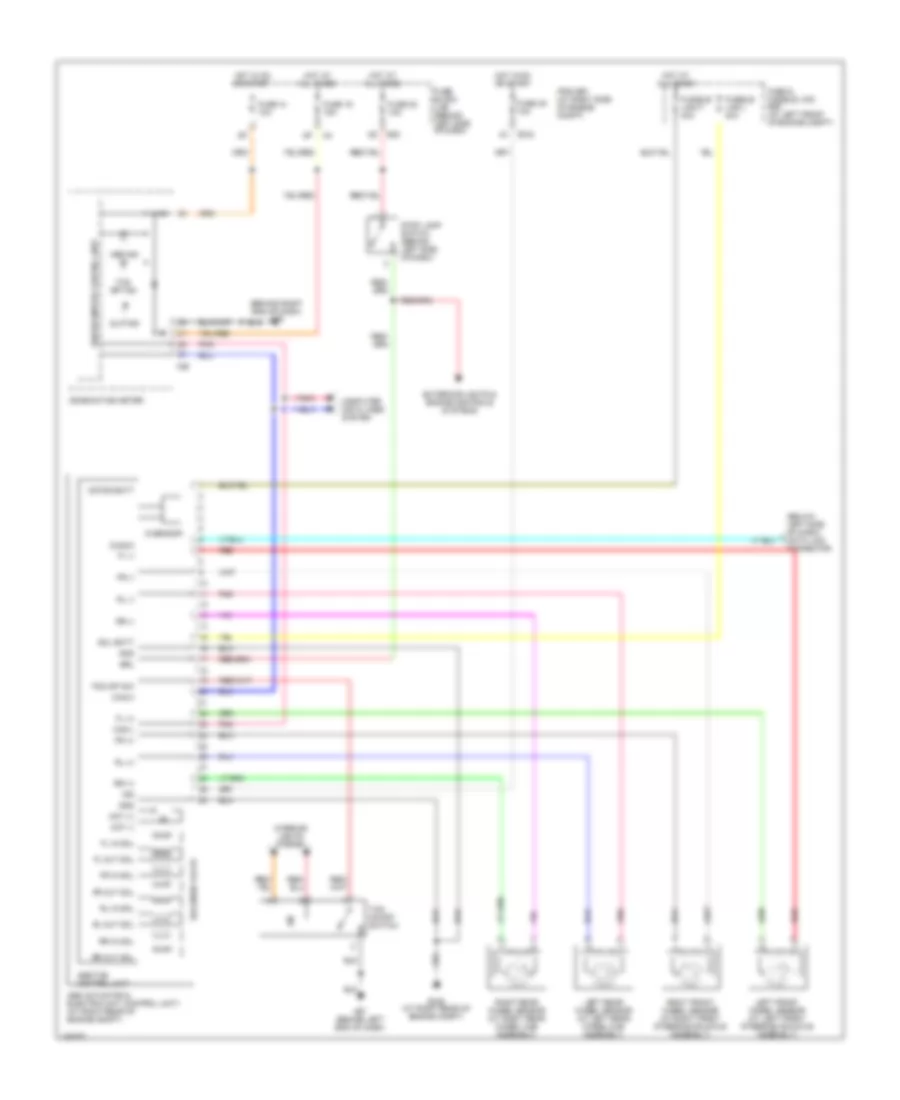
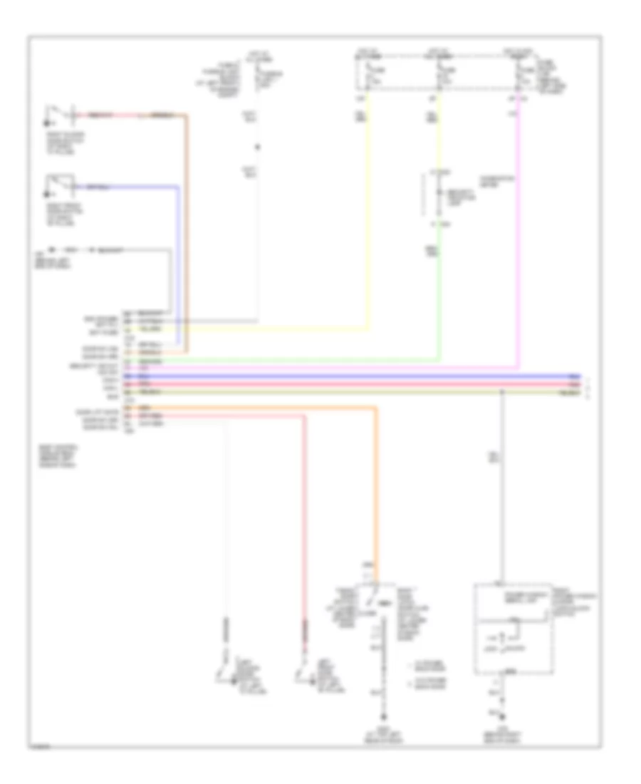
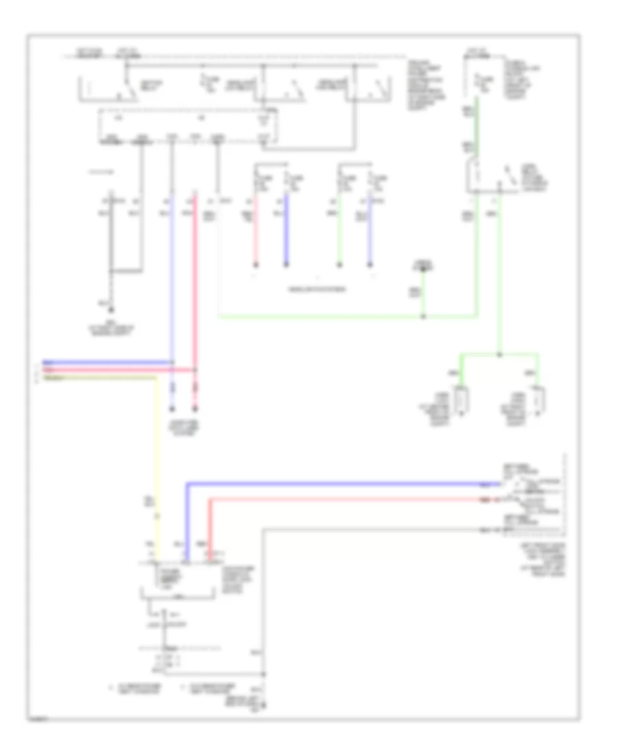
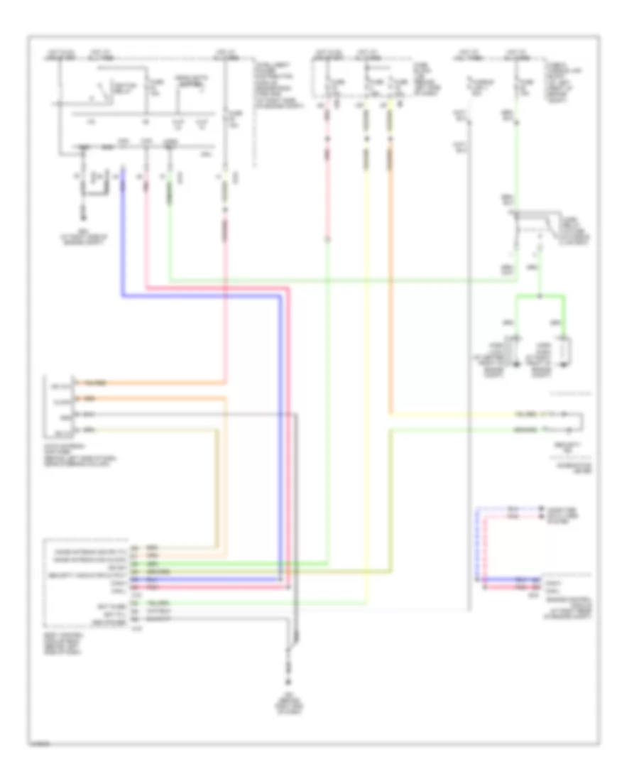
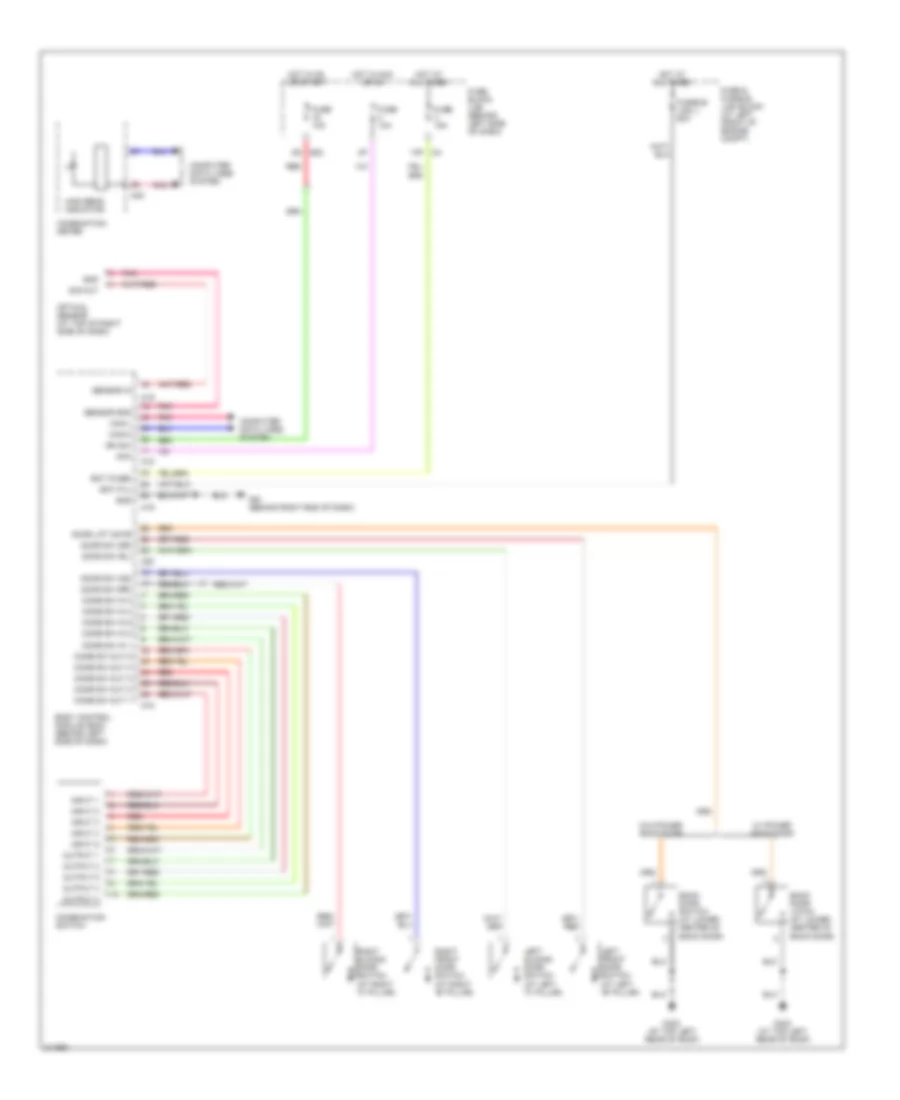
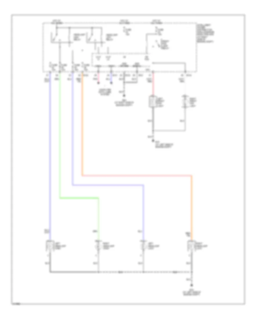
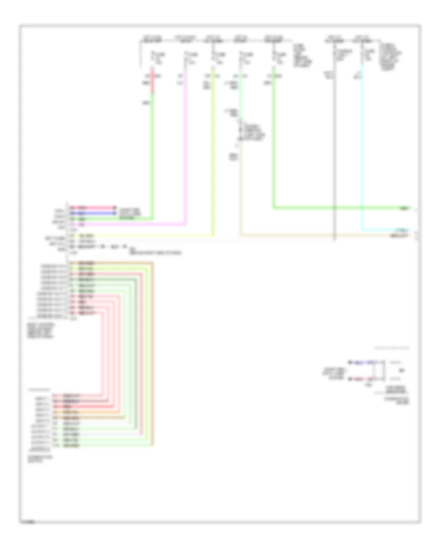
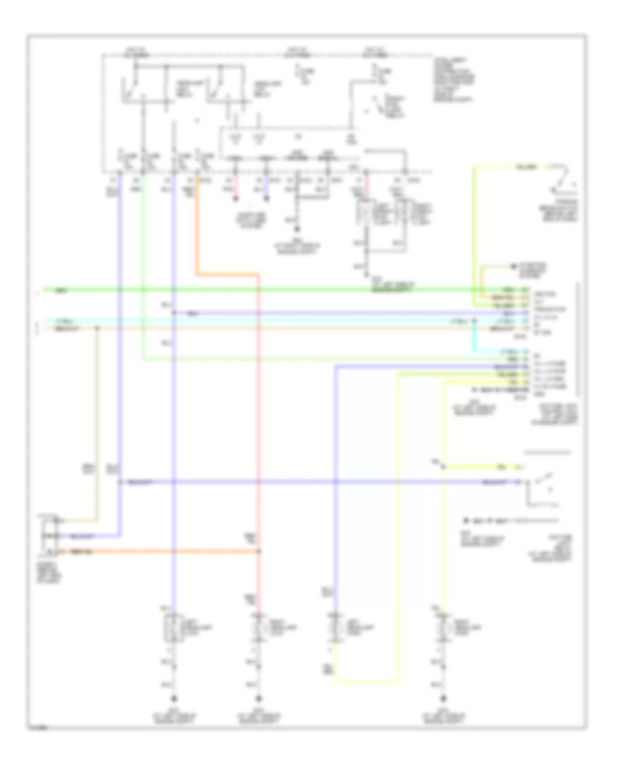
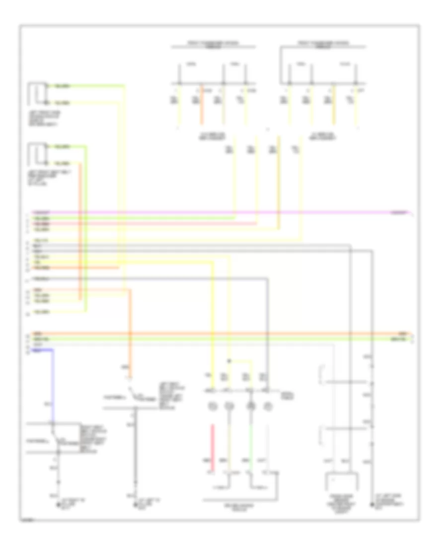
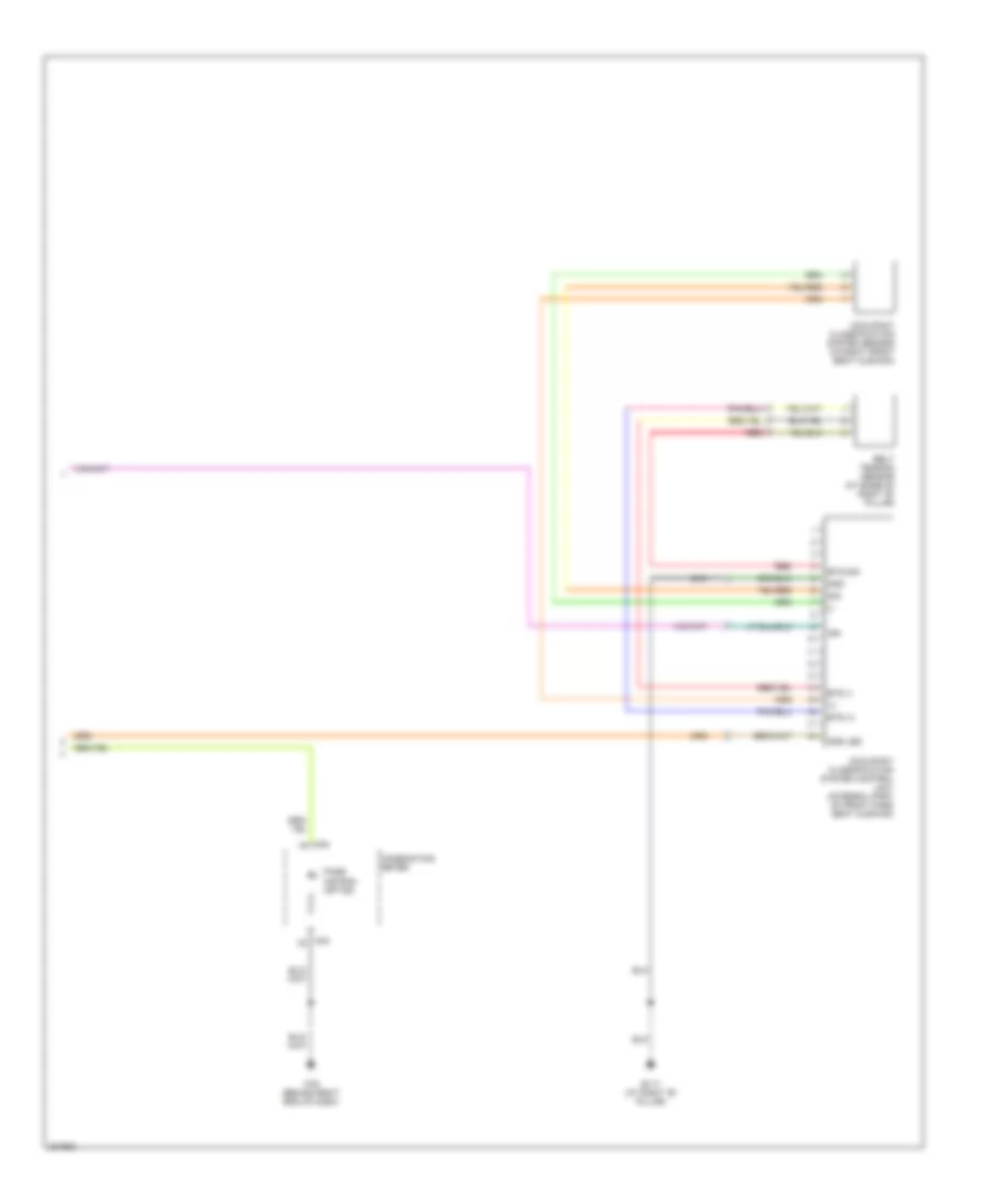
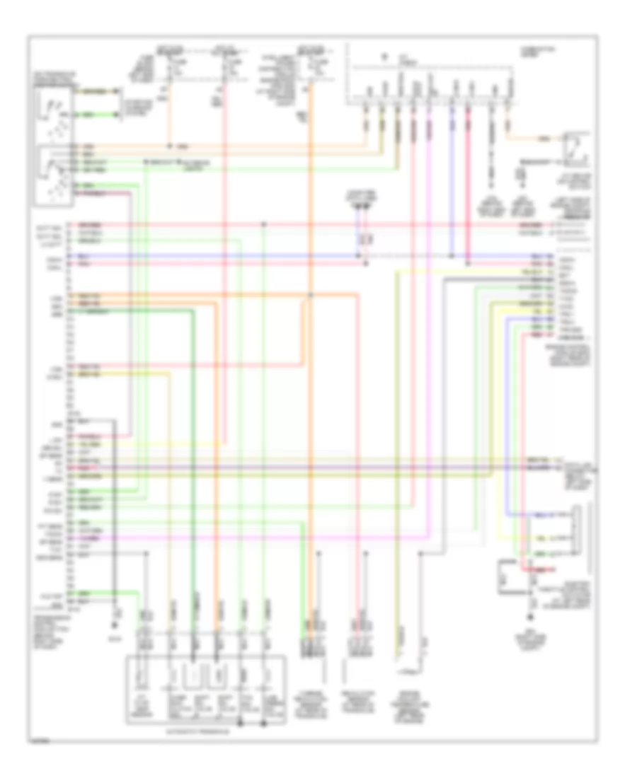
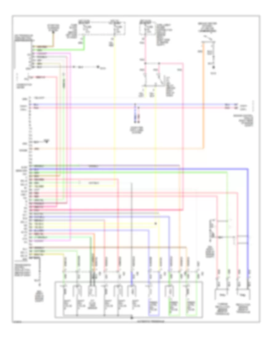
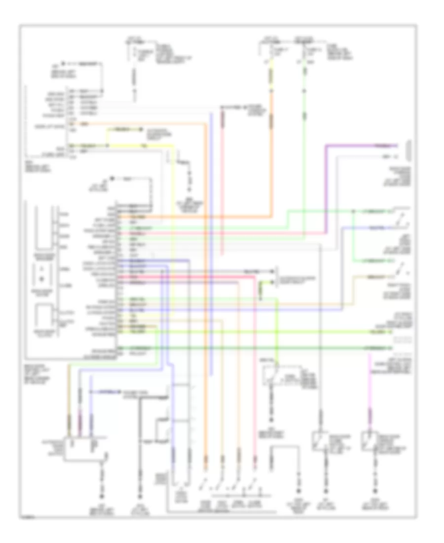
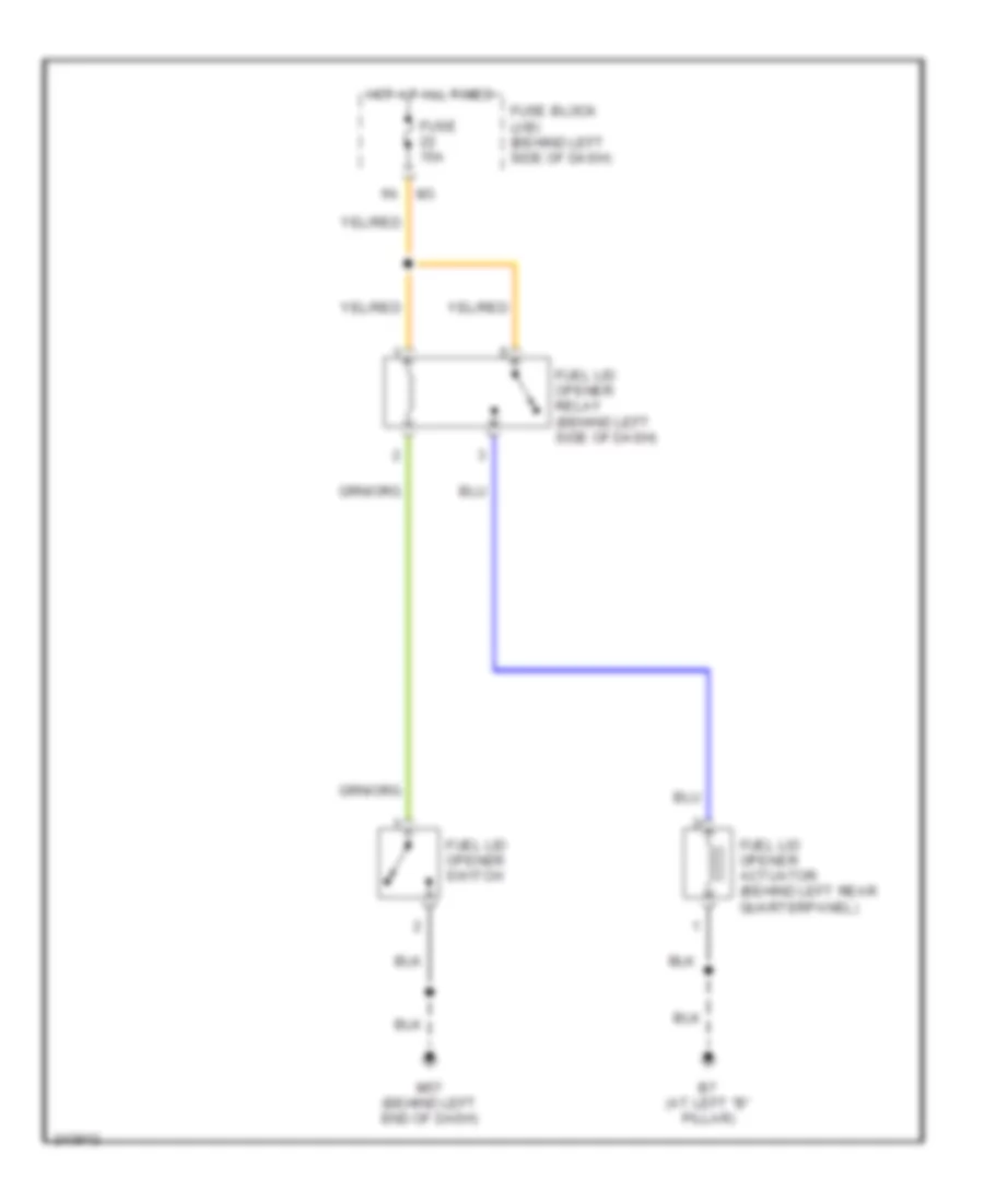
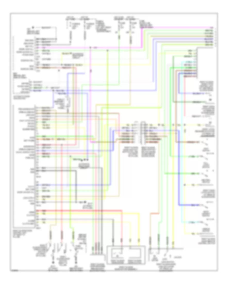
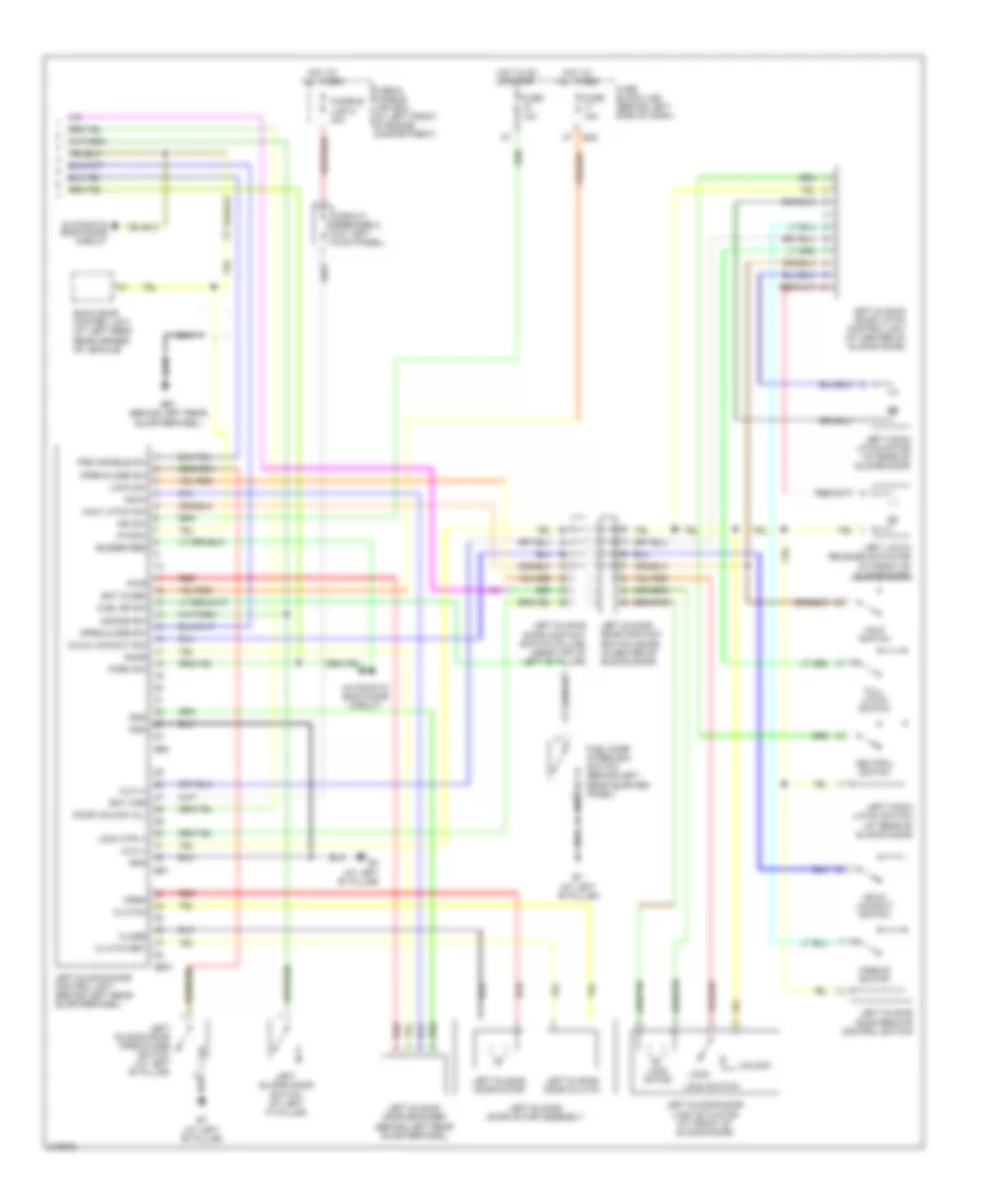
Diagram sections — 31 (88 total)
AIR CONDITIONING ANTI-LOCK BRAKES ANTI-THEFT BODY CONTROL MODULES COMPUTER DATA LINES COOLING FAN CRUISE CONTROL DEFOGGERS ENGINE PERFORMANCE EXTERIOR LIGHTS GROUND DISTRIBUTION HEADLIGHTS HORN INSTRUMENT CLUSTER INTERIOR LIGHTS MEMORY SYSTEMS NAVIGATION POWER DISTRIBUTION POWER DOOR LOCKS POWER MIRRORS POWER SEATS POWER TOP/SUNROOF POWER WINDOWS RADIO SHIFT INTERLOCK STARTING/CHARGING SUPPLEMENTAL RESTRAINTS TRANSMISSION TRUNK, TAILGATE, FUEL DOOR WARNING SYSTEMS WIPER/WASHER
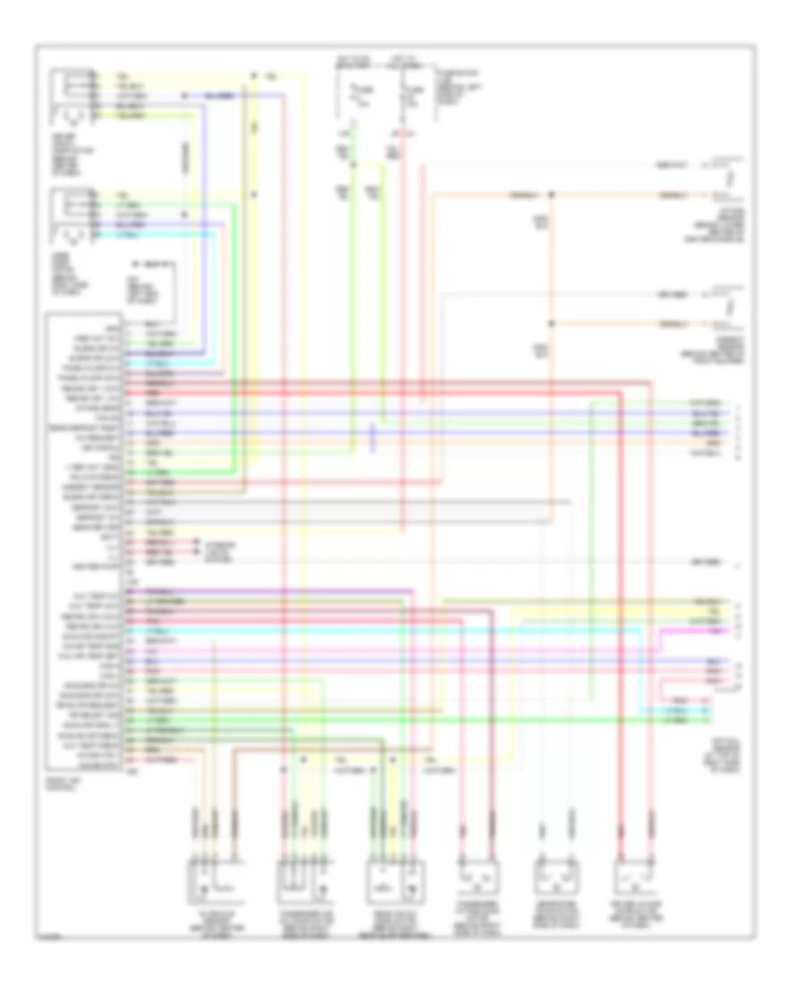
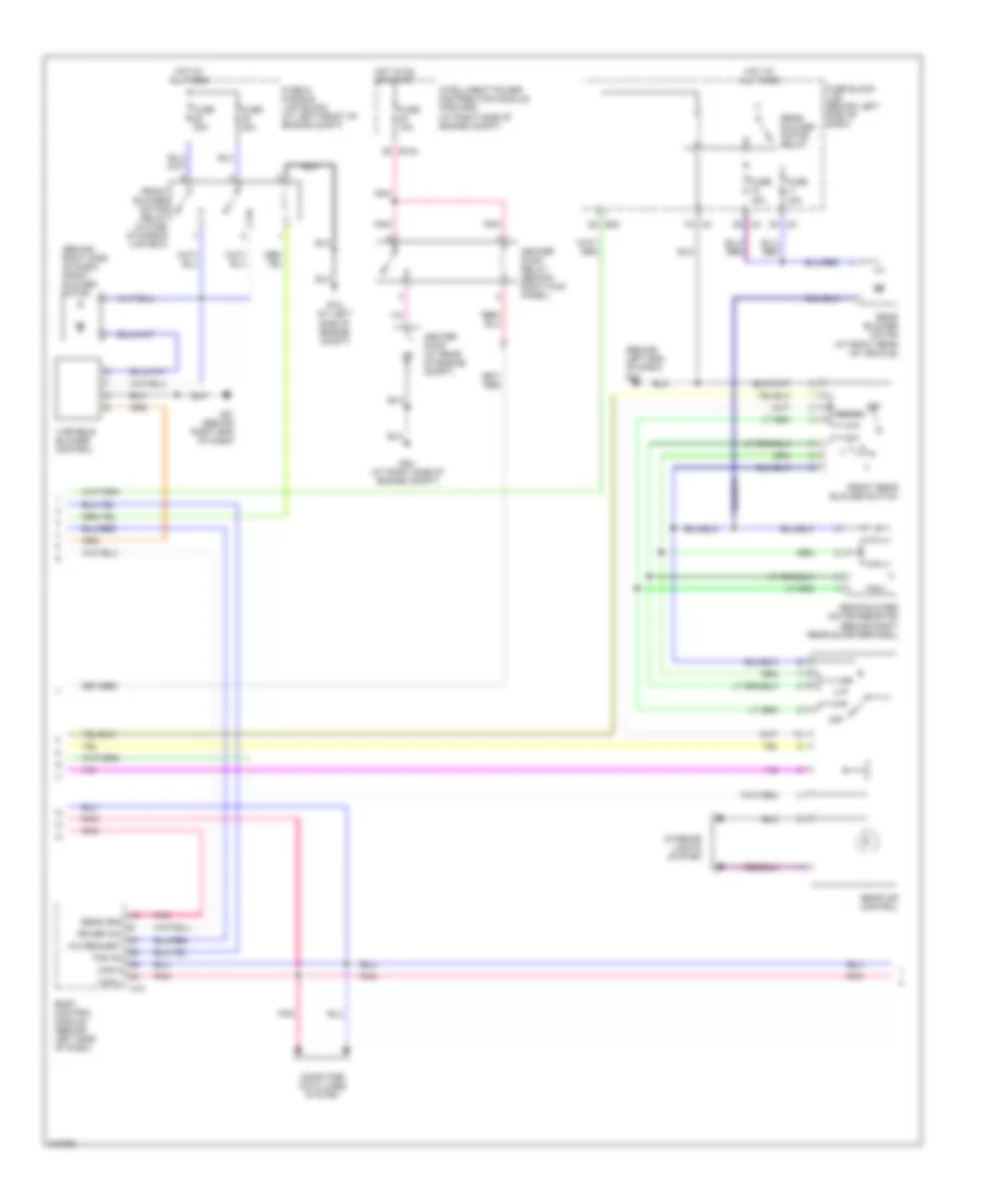
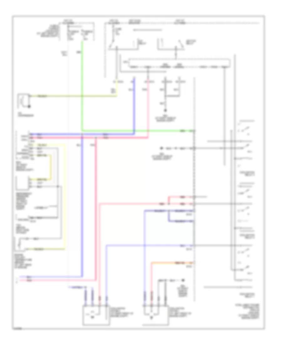
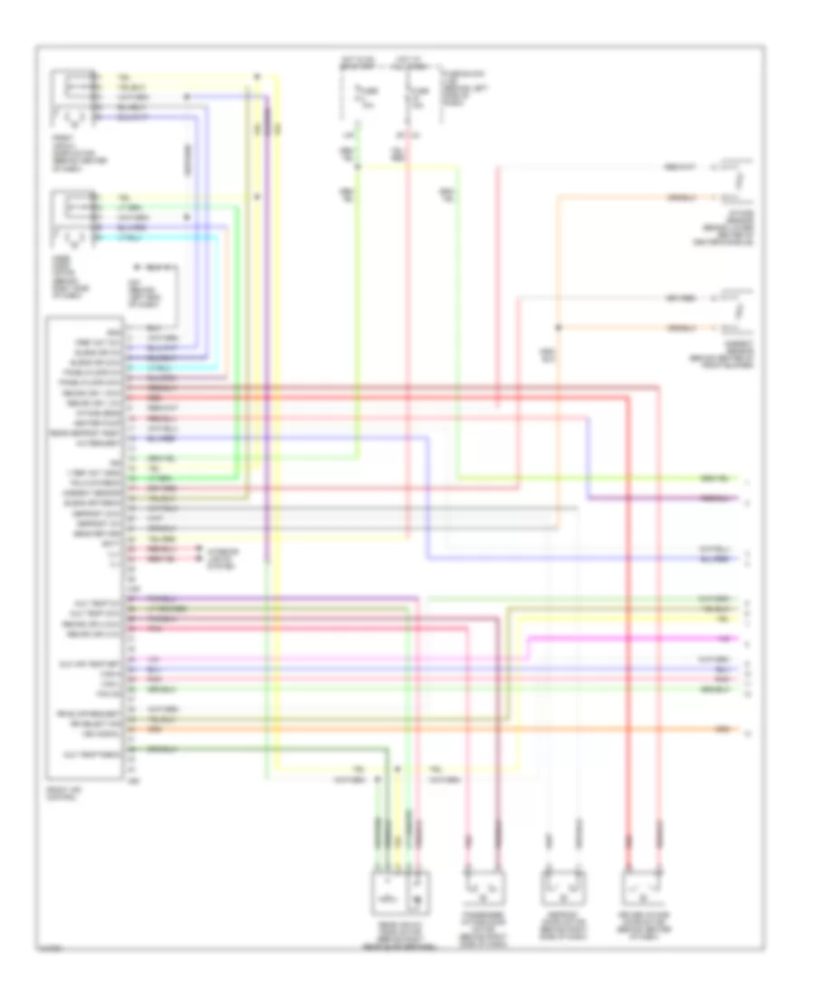
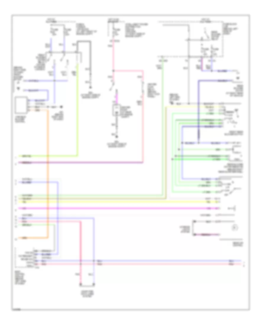
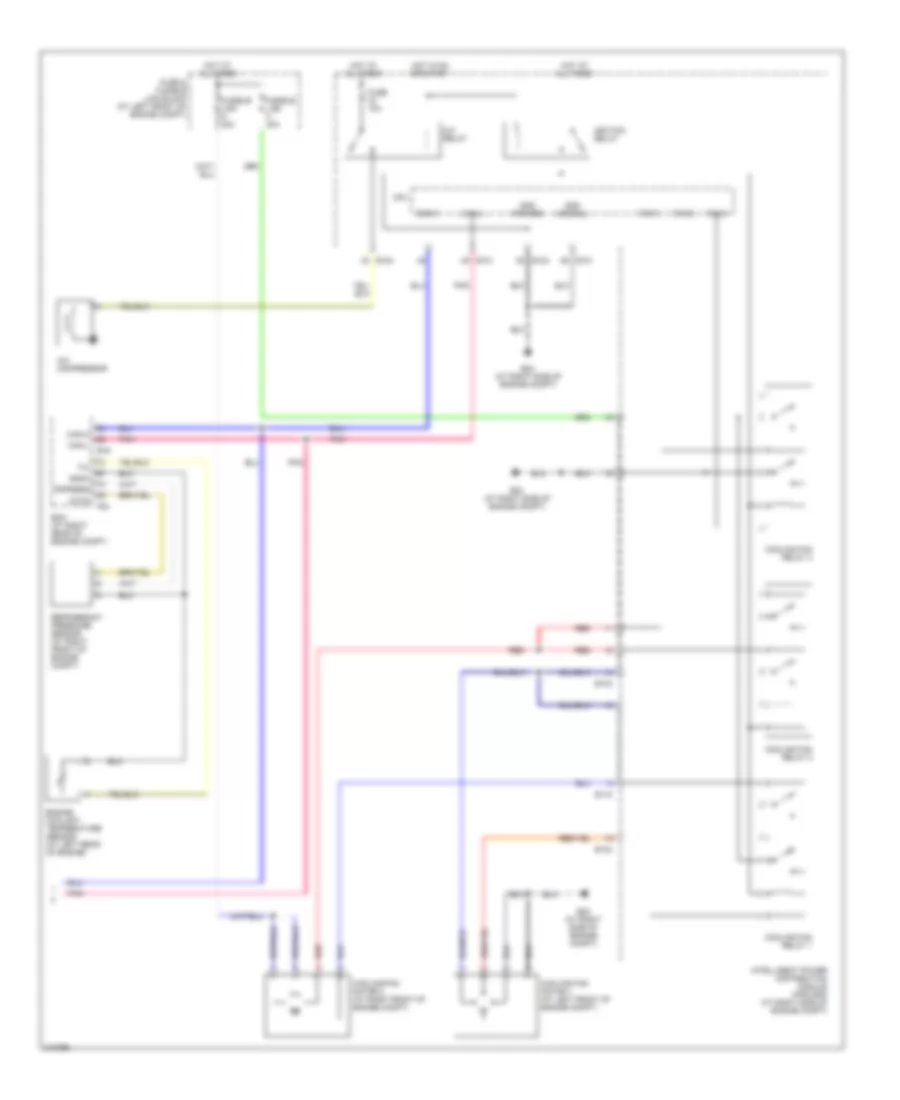
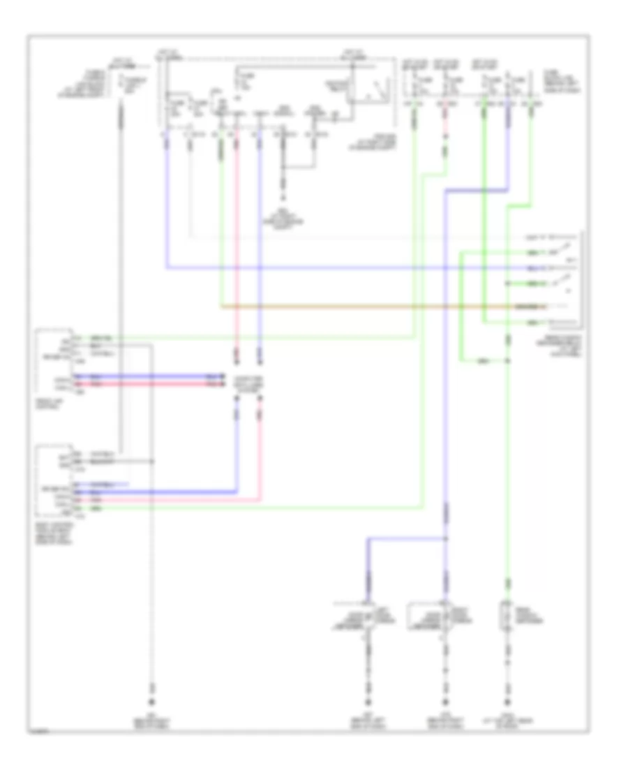
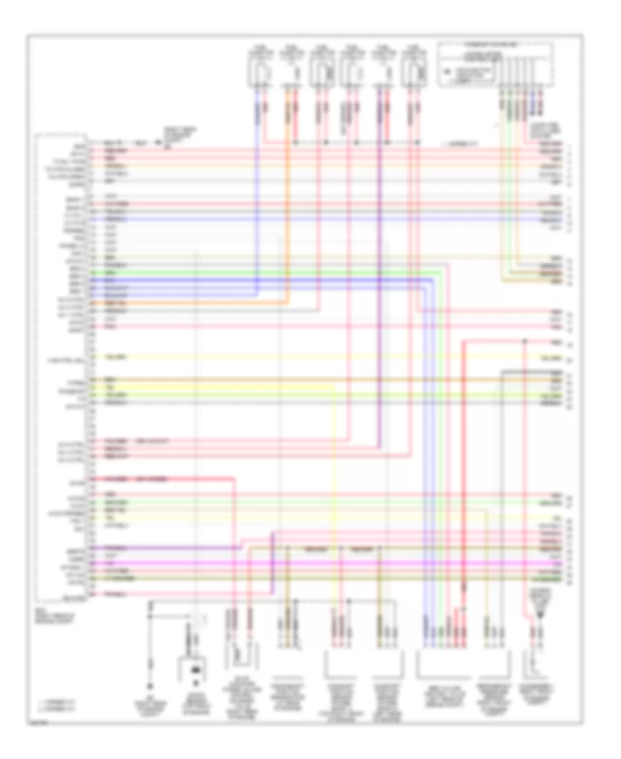
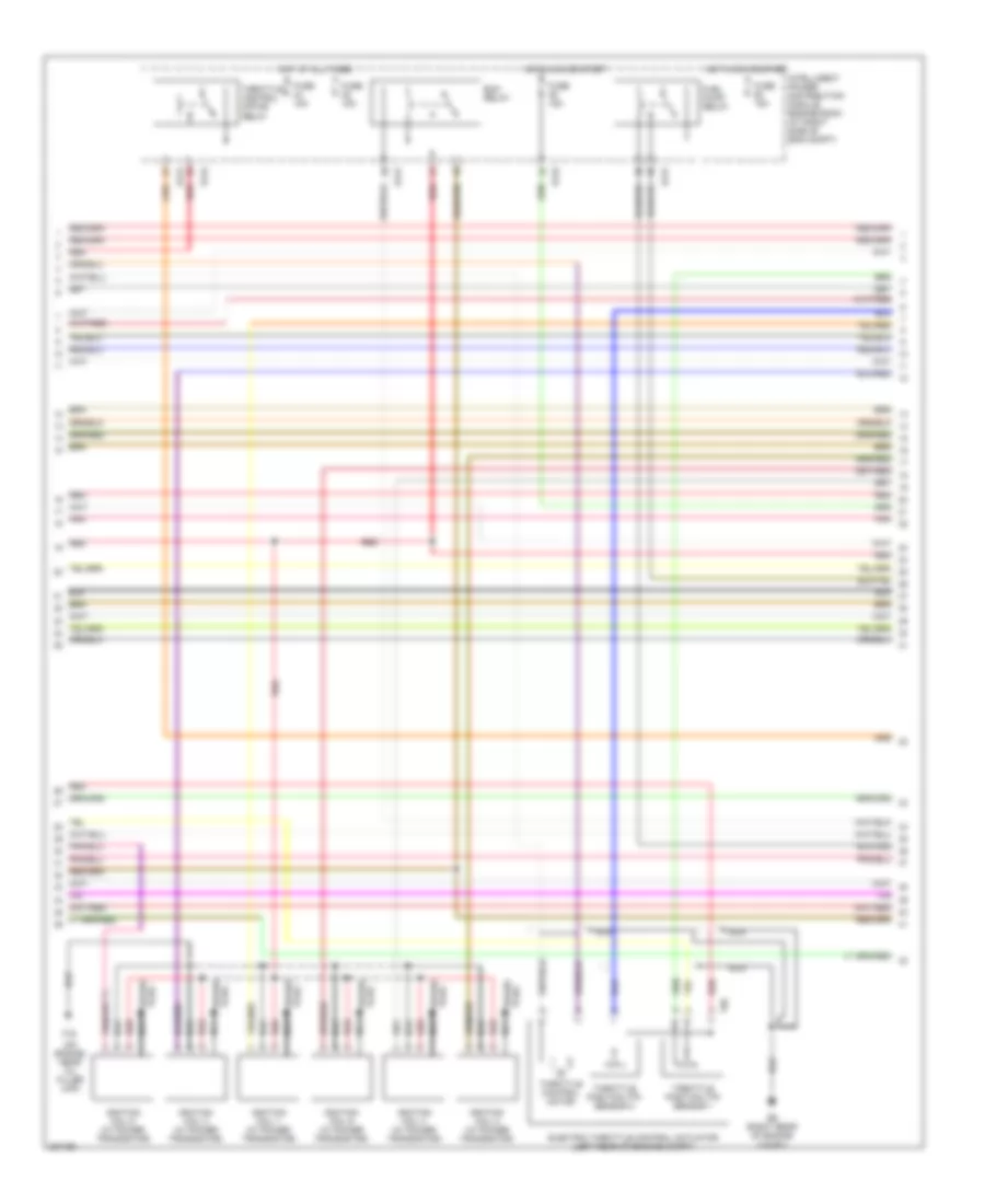
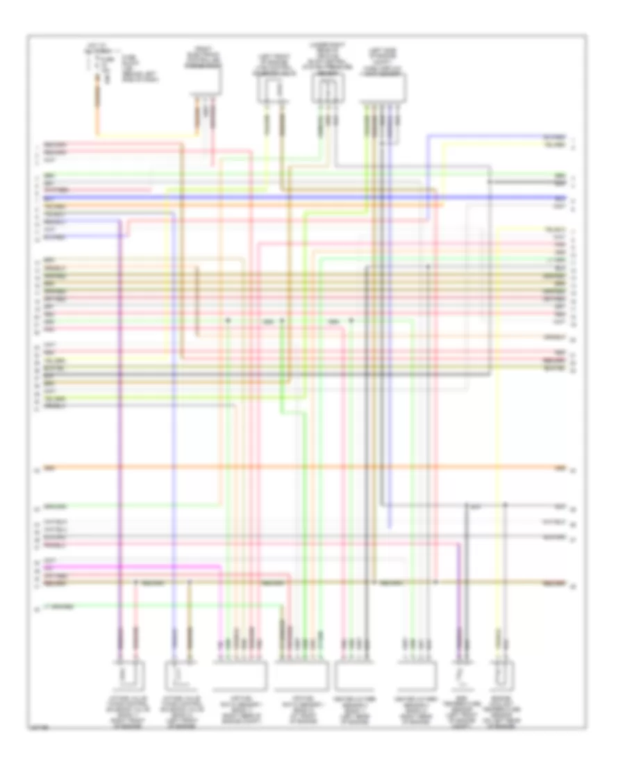
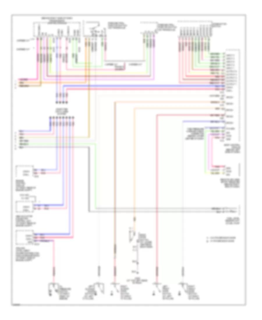
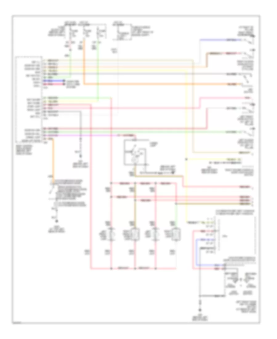
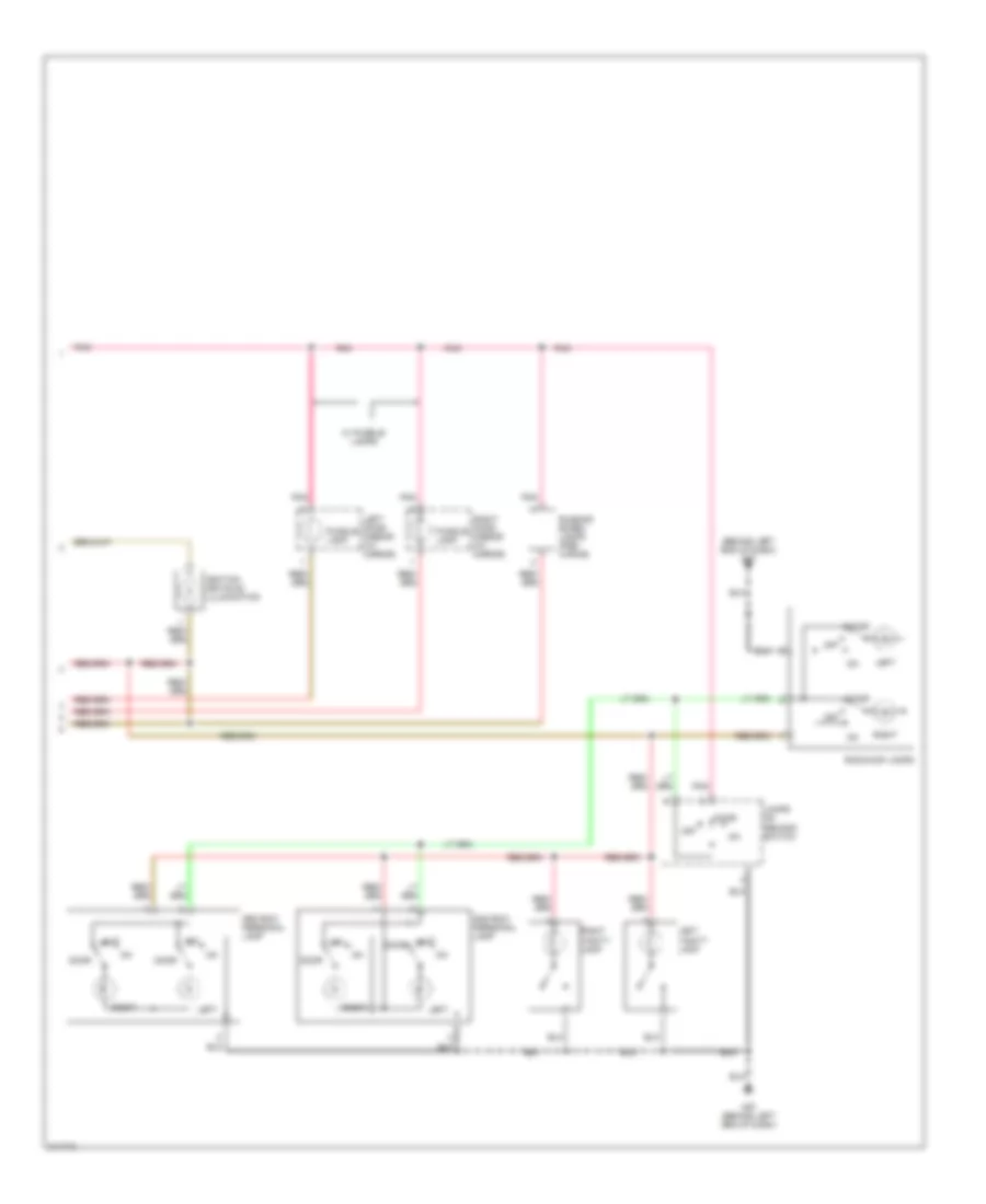
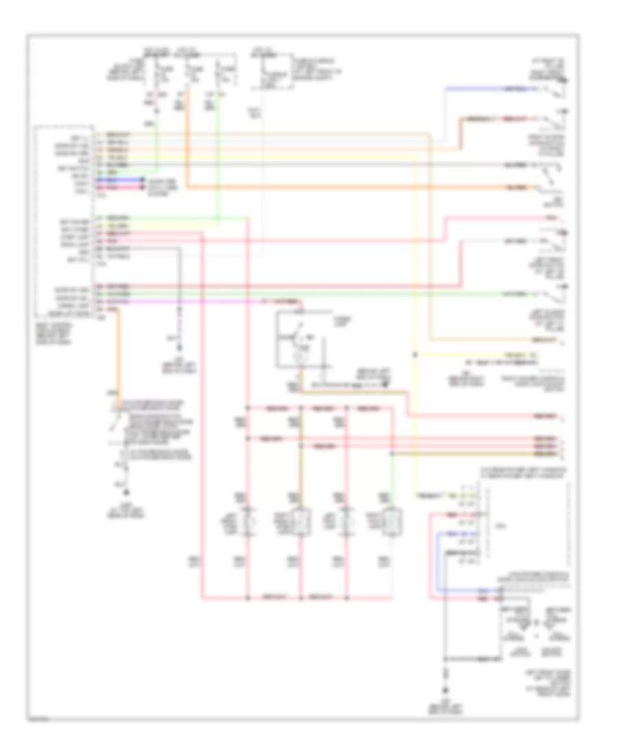
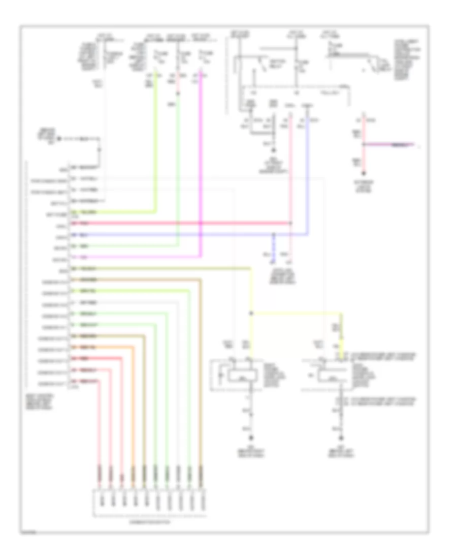
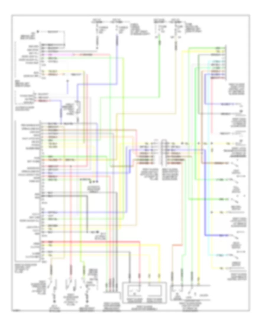
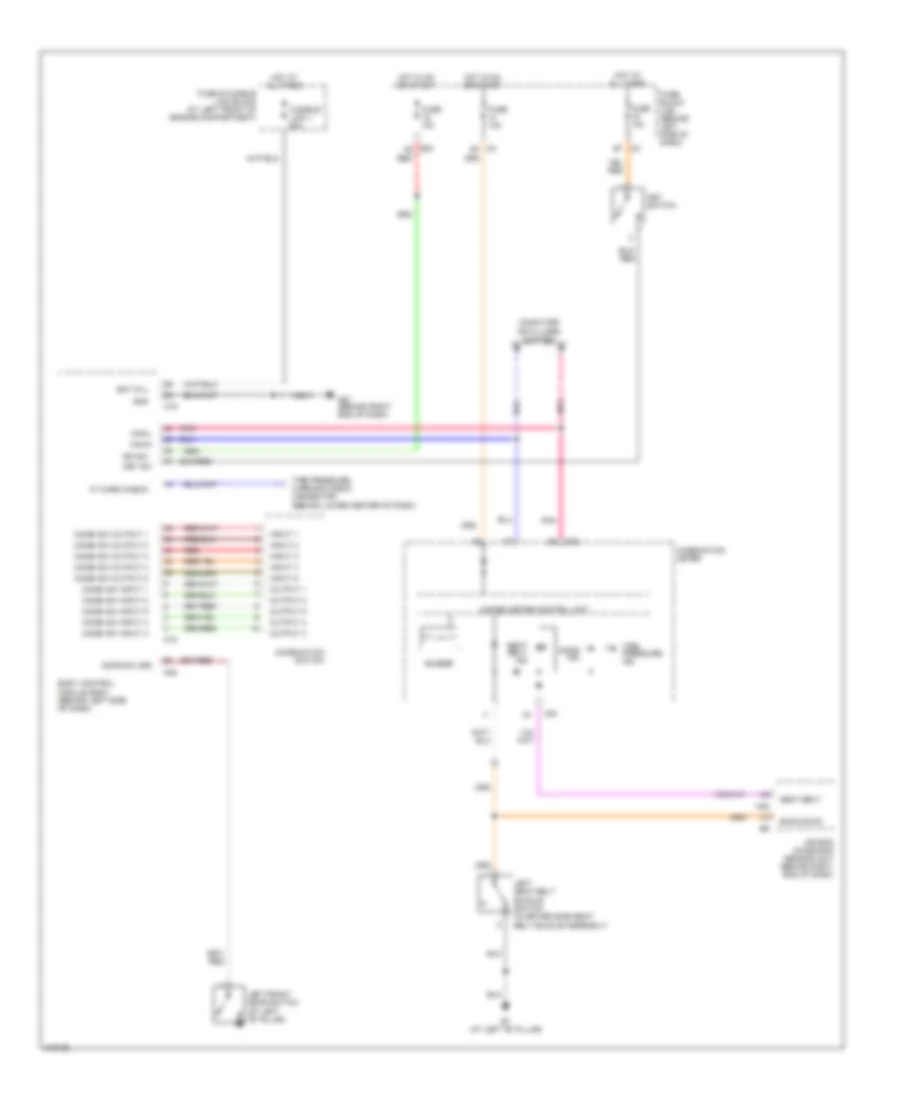
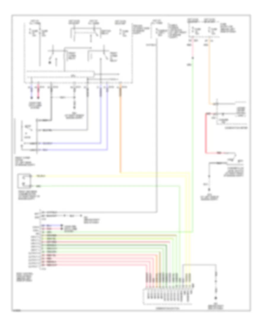
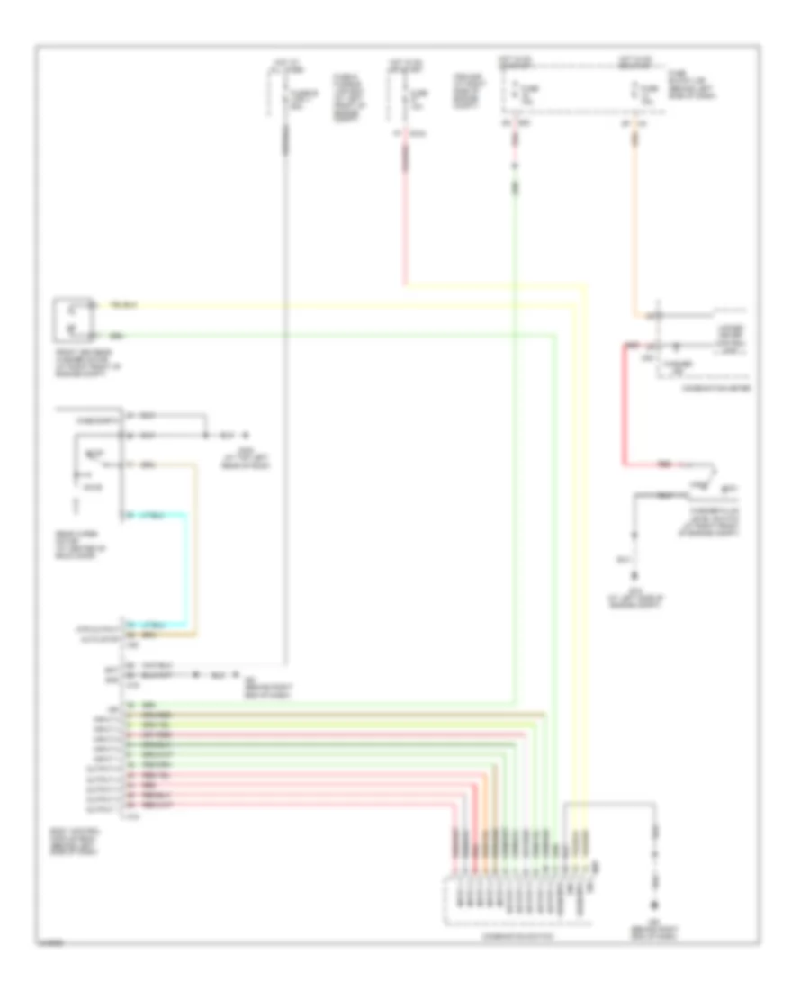
AIR CONDITIONING Automatic A/C Wiring Diagram (1 of 3) for Nissan Quest S 2006 List of elements for Automatic A/C Wiring Diagram (1 of 3) for Nissan Quest S 2006: 68 14p 8p m4 A/c request Ambient sensor Ambient sensor (behind center of front bumper) As blend dr ccw As blend dr cw As blnd dr fdbck Aux air temp set Aux temp ccw Aux temp cw Aux temp fdbck Batt Blend dr ccw Blend dr cw Blend dr fdbck Can-h Can-l Defrost ccw Defrost cw Defroster door motor (behind right side of dash) Driver air mix door motor (behind center of dash) Driver intake door motor (behind center of dash) Fan on Front air control Fuse 10a Fuse 15a Fuse block (j/b) (behind left side of dash) Gnd Heater pump Hot at all times Hot in on or start Ign Ill+ Ill- In-car mtr + In-car mtr - In-car temp sns In-vehicle sensor (behind center of dash) Intake sens Intake sensor (behind lower center of center console) Interior lights system M49 M50 M57 (behind left end of dash) Mode door motor (behind right side of dash) Optical sensor (at top of right side of dash) Panel/floor ccw Panel/floor cw Passenger air mix door motor (behind right side of dash) Passenger intake door motor (behind right side of dash) Pnk Pnl/flr fdbck Rear air mix door motor (behind right rear quarterpanel) Rear defrost rqst Recirc dr 1 ccw Recirc dr 1 cw Recirc dr 2 ccw Recirc dr 2 cw Red Rr blwr request Rr select sig Sens return Sunload sns lt Sunload sns rt V ref act (gnd) Vbc signal Vref act (5v) Automatic A/C Wiring Diagram (2 of 3) for Nissan Quest S 2006 List of elements for Automatic A/C Wiring Diagram (2 of 3) for Nissan Quest S 2006: 40 (behind left end of dash) m57 (behind right side of dash) front blower motor 3q e30 A/c request Body control module (behind left side of dash) Can-h Can-l Computer data lines system E122 E15 (at left side of engine compt) E24 (at right side of engine compt) Fan on Front blower motor relay (in fuse & fusible link box) Front rear blower switch Fuse & fusible link block (at left front of engine compt) Fuse 10a Fuse 15a Fuse 20a Fuse block (j/b) (behind left side of dash) Heater pump (at rear of engine compt) Heater pump relay (behind right kick panel) Hot at all times Hot in on or start Intelligent power distribution module (ipdm e/r) (at right side of engine compt) Interior lights system M18 M3 3n M3 7n M3 8n M61 (behind right end of dash) Off Pnk Rear Rear air control Rear blower motor (at right rear of vehicle) Rear blower motor relay Rear blower motor resistor (behind right rear quarterpanel) Rr def sw Sens gnd Variable blower control Automatic A/C Wiring Diagram (3 of 3) for Nissan Quest S 2006 List of elements for Automatic A/C Wiring Diagram (3 of 3) for Nissan Quest S 2006: 42 4 speed a/t A/c compressor A/c relay Avcc Can-h Can-l Cooling fan motor 1 (at left front of engine compt) Cooling fan motor 2 (at right front of engine compt) Cooling fan relay 1 Cooling fan relay 2 Cooling fan relay 3 Cpu E118 E121 E123 E124 E143 E16 E24 (at right side of engine compt) Ecm (at right rear of engine compt) Engine coolant temperature sensor (at left rear of engine) F54 Fan 1 Fan 2 Fan 3 Fuse & fusible link block (at left front of engine compt) Fuse 10a Fusible link g 40a Fusible link h 40a Gnd (power) Gnd (signal) Gnda Hot at all times Hot in on or start Ignition relay Intelligent power distribution module (ipdm e/r) (at right side of engine compt) Pdpress Pnk Red Refrigerant pressure sensor (at right front of engine compt) Sns gnd Tcm (behind right side of dash) Manual A/C Wiring Diagram (1 of 3) for Nissan Quest S 2006 List of elements for Manual A/C Wiring Diagram (1 of 3) for Nissan Quest S 2006: 57 14p 8p m4 A/c request Ambient sensor Ambient sensor (behind center of front bumper) Aux air temp set Aux temp ccw Aux temp cw Aux temp fdbck Batt Blend dr ccw Blend dr cw Blend dr fdbck Can-h Can-l Defrost ccw Defrost cw Defrost door motor (behind right side of dash) Driver intake door motor (behind center of dash) Fan on Front air control Front air mix door motor (behind center of dash) Fuse 10a Fuse 15a Fuse block (j/b) (behind left side of dash) Gnd Heater pump Hot at all times Hot in on or start Ign Ill+ Ill- Intake sens Intake sensor (behind lower center of center console) Interior lights system M49 M50 M57 (behind left end of dash) Mode door motor (behind right side of dash) Panel/floor ccw Panel/floor cw Passenger intake door motor (behind right side of dash) Pnk Pnl/flr fdbck Rear air mix door motor (behind right rear quarterpanel) Rear defrost rqst Recirc dr 1 ccw Recirc dr 1 cw Recirc dr 2 ccw Recirc dr 2 cw Red Rr blwr request Rr select sig Sens return V ref act (gnd) Vbc signal Vref act (5v) Manual A/C Wiring Diagram (2 of 3) for Nissan Quest S 2006 List of elements for Manual A/C Wiring Diagram (2 of 3) for Nissan Quest S 2006: 36 (behind left end of dash) m57 (behind right side of dash) front blower motor A/c request Body control module (behind left side of dash) Can-h Can-l Computer data lines system E122 E24 (at right side of engine compt) E30 6q Fan on Front blower motor relay (in fuse & fusible link box) Front rear blower switch Fuse & fusible link block (at left front of engine compt) Fuse 10a Fuse 15a Fuse 20a Fuse block (j/b) (behind left side of dash) Heater pump (at rear of engine compt) Heater pump relay (behind right kick panel) Hot at all times Hot in on or start Intelligent power distribution module (ipdm e/r) (at right side of engine compt) Interior lights system M18 M3 3n M61 (behind right end of dash) Off Pnk Rear Rear air control Rear blower motor (at right rear of vehicle) Rear blower motor relay Rear blower motor resistor (behind right rear quarterpanel) Rr def sw Variable blower control Manual A/C Wiring Diagram (3 of 3) for Nissan Quest S 2006 List of elements for Manual A/C Wiring Diagram (3 of 3) for Nissan Quest S 2006: 38 A/c compressor A/c relay Avcc Can-h Can-l Cooling fan motor 1 (at left front of engine compt) Cooling fan motor 2 (at right front of engine compt) Cooling fan relay 1 Cooling fan relay 2 Cooling fan relay 3 Cpu E118 E121 E123 E124 E16 E24 (at right side of engine compt) Ecm (at right rear of engine compt) Engine coolant temperature sensor (at left rear of engine) F54 Fan 1 Fan 2 Fan 3 Fuse & fusible link block (at left front of engine compt) Fuse 10a Fusible link g 40a Fusible link h 40a Gnd (power) Gnd (signal) Gnda Hot at all times Hot in on or start Ignition relay Intelligent power distribution module (ipdm e/r) (at right side of engine compt) Pdpress Pnk Red Refrigerant pressure sensor (at right front of engine compt)
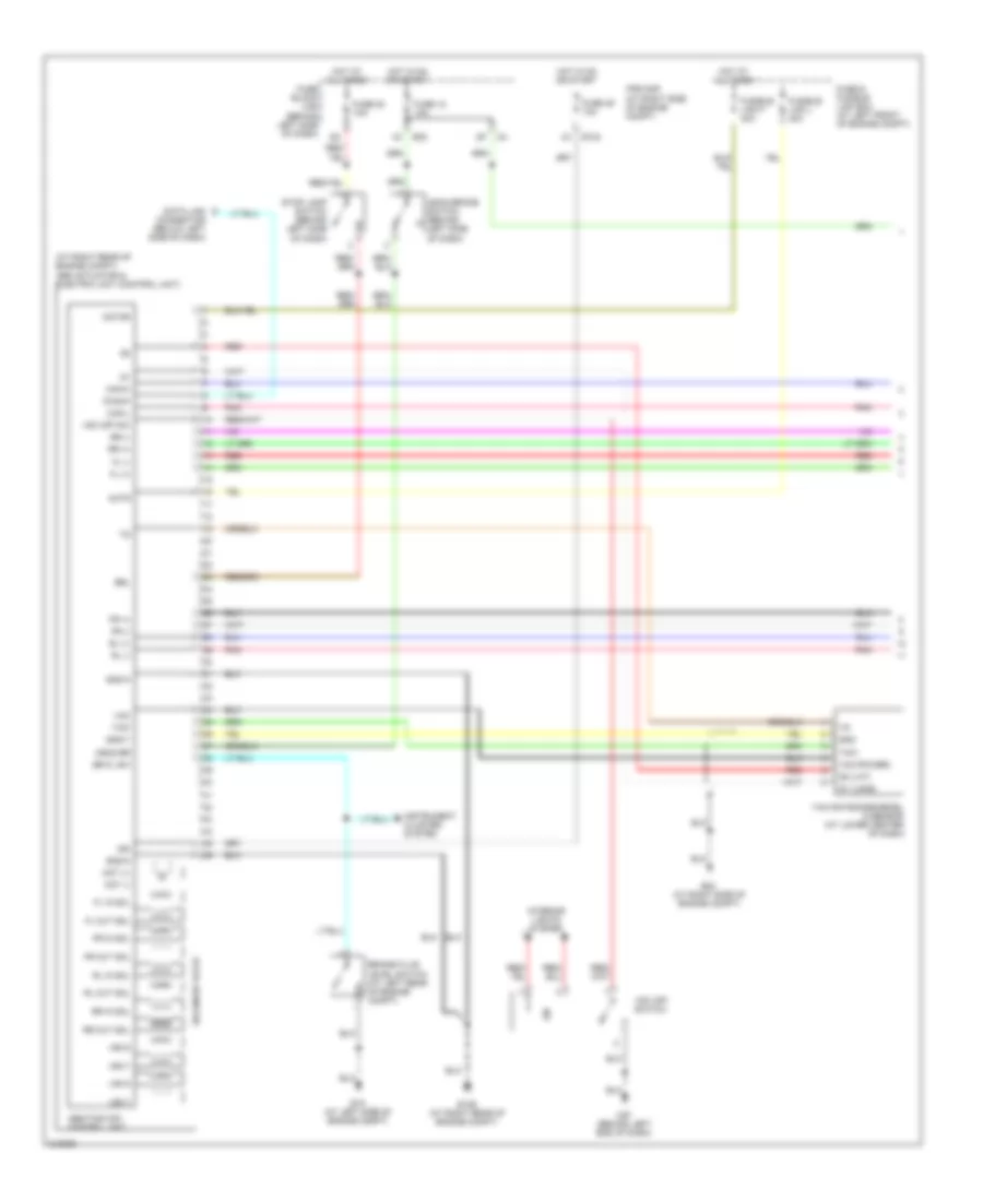
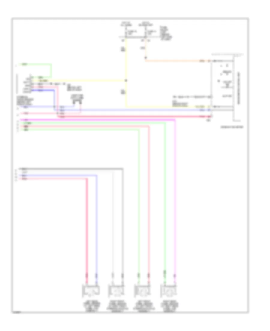
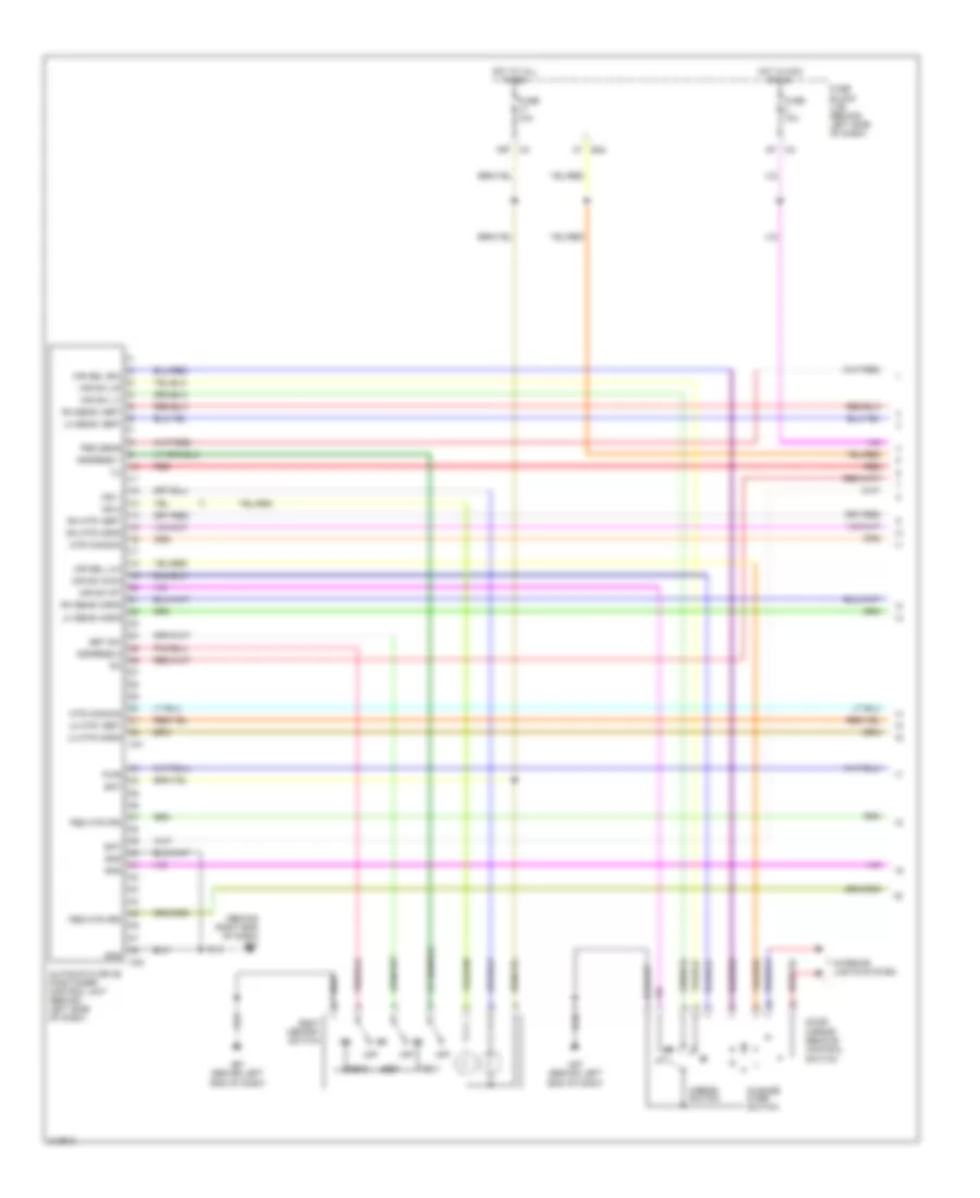
ANTI-LOCK BRAKES Anti-lock Brakes Wiring Diagram, with Traction Control & Stability Assist (1 of 2) for Nissan Quest S 2006 List of elements for Anti-lock Brakes Wiring Diagram, with Traction Control & Stability Assist (1 of 2) for Nissan Quest S 2006: 70 (at right rear of engine compt) abs actuator & electric unit (control unit) Abs/tcs/vdc control unit Actr Ascd br Ascd brake switch (behind left side of dash) Br fl sw Brake fluid level switch (at left rear of engine compt) Brl Can-h Can-l Data link connector (below left side of dash) Diag-k E124 E126 (at right rear of engine compt) E15 (at left side of engine compt) E24 (at right side of engine compt) E30 Fl (+) Fl (-) Fl in sol Fl out sol Fr (+) Fr (-) Fr in sol Fr out sol Fuse & fusible link box (at left front of engine compt) Fuse 12 10a Fuse 20 10a Fuse 49 10a Fuse block (j/b) (behind left side of dash) Fusible link f 40a Fusible link l 40a G1 (long) G2 (lat) Gnd Gnd-a Gnd-m Gnd-y Hot at all times Hot in on or start Hsv1 Hsv2 Ign Instrument cluster system Interior lights system Ipdm e/r (at right side of engine compt) M57 (behind left end of dash) Mot (+) Mot (-) Motor Pnk Red Rl (+) Rl (-) Rl in sol Rl out sol Rr (+) Rr (-) Rr in sol Rr out sol Solenoid valve Stop lamp switch (behind left side of dash) Usv1 Usv2 Vcc Vcc (power) Vdc off sw Vdc off switch Yaw Yaw rate/side/decel g sensor (at lower center of dash) Anti-lock Brakes Wiring Diagram, with Traction Control & Stability Assist (2 of 2) for Nissan Quest S 2006 List of elements for Anti-lock Brakes Wiring Diagram, with Traction Control & Stability Assist (2 of 2) for Nissan Quest S 2006: 26 Abs ind Batt Can-h Can-l Combination meter Computer data lines system Fuse 14 10a Fuse 19 15a Fuse block (j/b) (behind left side of dash) Gnd Hot at all times Hot in on or start Ign Left front wheel sensor (at left front steering knuckle assembly) Left rear wheel sensor (at left rear wheel hub assembly) M23 M57 (behind left end of dash) M79 (behind right side of dash) Pnk Red Right front wheel sensor (at right front steering knuckle assembly) Right rear wheel sensor (at right rear wheel hub assembly) Slip ind Steering angle sensor (behind left side of dash) Unified meter control unit Vdc off ind Anti-lock Brakes Wiring Diagram, with Traction Control for Nissan Quest S 2006 List of elements for Anti-lock Brakes Wiring Diagram, with Traction Control for Nissan Quest S 2006: 65 (behind right end of dash) m79 (below left side of dash) data link connector Abs actuator & electric unit (control unit) (at right rear of engine compt) Abs ind Abs/tcs control unit Brl Can-h Can-l Combination meter Computer data lines system Diag-k E124 E126 (at right rear of engine compt) E30 Exterioir lights & engine controls systems Fl (+) Fl (-) Fl in sol Fl out sol Fr (+) Fr (-) Fr in sol Fr out sol Fuse & fusible link box (at left front of engine compt) Fuse 14 10a Fuse 19 15a Fuse 20 10a Fuse 49 10a Fuse block (j/b) (behind left side of dash) Fusible link f 40a Fusible link l 40a G sensor Gnd Hot at all times Hot in on or start Ign Interior lights system Ipdm e/r (at right side of engine compt) Left front wheel sensor (at left front steering knuckle assembly) Left rear wheel sensor (at left rear wheel hub assembly) M23 M57 (behind left end of dash) Mot (+) Mot (-) Motor batt Pnk Red Right front wheel sensor (at right front steering knuckle assembly) Right rear wheel sensor (at right rear wheel hub assembly) Rl (+) Rl (-) Rl in sol Rl out sol Rr (+) Rr (-) Rr in sol Rr out sol Slip ind Sol batt Solenoid valve Stop lamp switch (behind left side of dash) Tcs off ind Tcs off sw Tcs on/off switch Unified meter control unit
ANTI-THEFT Forced Entry Wiring Diagram (1 of 2) for Nissan Quest S 2006 List of elements for Forced Entry Wiring Diagram (1 of 2) for Nissan Quest S 2006: 49 13p 4p m4 Acc sw Back door latch (door ajar switch) (at lower center of back door) Back door switch (at lower center of back door) Bat (fuse) Body control module (bcm) (behind left side of dash) Bus Can-h Can-l Close Combination meter Cpu D403 (at top left rear of roof) Door lift gate Door sw (as) Door sw (dr) Door sw (rl) Door sw (rr) Fuse & fusible link block (at left front of engine compt) Fuse 10a Fuse 15a Fuse block (j/b) (behind left side of dash) Fusible link j 50a Gnd Gnd (power) bat (f/l) Hot at all times Hot in acc or on Left front door switch (at left "b" pillar) Left sliding door switch (at left "c" pillar) Lock M18 M19 M20 M23 M24 M57 (behind left end of dash) M79 (behind right end of dash) Open Pnk Power window serial link Right front door switch (at right "b" pillar) Right power window & door lock/unlock switch Right sliding door switch (at right "c" pillar) Security ind out Security indicator lamp Unlock W/ power back door W/o power back door Forced Entry Wiring Diagram (2 of 2) for Nissan Quest S 2006 List of elements for Forced Entry Wiring Diagram (2 of 2) for Nissan Quest S 2006: 42 (behind left end of dash) m57 (w/ rear power vent windows) (w/o rear power vent windows) +ig Between full stroke & n Can h Can l Computer data lines system Cpu E121 E122 E124 E24 (at right side of engine compt) Full stroke lock switch Fuse & fusible link block (at left front of engine compt) Fuse 10a Fuse 15a Gnd Gnd (power) Gnd (signal) H/lp hi H/lp lo Headlamp high relay Headlamp low relay Headlights systems Horn (high) (at right front of engine compt) Horn (low) (at center front of engine compt) Horn relay (in fuse & fusible link box) Horn rly Horns system Hot at all times Hot in on or start Ignition relay Ipdm e/r (intelligent power distribution module engine room) (at right side of engine compt) Left front door lock assembly (key cylinder switch) (at rear of left front door) Lock Main power window & door lock/ unlock switch Pnk Power window serial link Red Unlock Unlock switch full stroke Immobilizer Wiring Diagram for Nissan Quest S 2006 List of elements for Immobilizer Wiring Diagram for Nissan Quest S 2006: 50 +ig 13p Bat (f/l) Bat (fuse) Body control module (bcm) (behind left side of dash) Can h Can l Can-h Can-l Clock Combination meter Computer data lines system Cpu E121 E124 E16 E24 (at right side of engine compt) E30 Engine control module (at right rear of engine compt) Fuse & fusible link block (at left front of engine compt) Fuse 10a Fuse 15a Fuse block (j/b) (behind left side of dash) Fusible link j 50a Gnd Gnd (power) H/lp hi H/lp lo Headlights system Horn (high) (at right front of engine compt) Horn (low) (at center front of engine compt) Horn relay (in fuse & fusible link box) Horn rly Hot at all times Hot in on and start Ign sw Ignition relay Immob antenna sig (clock) Immob antenna sig (rx,tx) Intelligent power distribution module engine room (ipdm e/r) (at right side of engine compt) M18 M19 M61 (behind right end of dash) Nats antenna amplifier (behind left side of dash, near steering column) Pnk Red Rx,tx Security ind Security indicator output Vb (12v)
BODY CONTROL MODULES Body Control Modules Wiring Diagram for Nissan Quest S 2006 List of elements for Body Control Modules Wiring Diagram for Nissan Quest S 2006: 86 (behind right end of dash) 13p m4 4p m4 5q e30 A/c request Acc sw Air conditioning system Anti-theft system Bat (f/l) Bat (fuse) Bat saver Body control module (bcm) (behind left side of dash) Can-h Can-l Cargo lamp Comb sw in 1 Comb sw in 2 Comb sw in 3 Comb sw in 4 Comb sw in 5 Comb sw out 1 Comb sw out 2 Comb sw out 3 Comb sw out 4 Comb sw out 5 Computer data lines system Defogger, air conditioning system Door lift gate Door locks system Door sw (as) Door sw (dr) Door sw (rl) Door sw (rr) Dr lck out (all) Dr unlk out (dr) Exterior lights system Fan on Flash lamp Flasher out lt Flasher out rt Fuse & fusible link block (at left front of engine compt) Fuse 10a Fuse 15a Fuse block (j/b) (behind left side of dash) Fusible link j 50a Gnd Hazard sw Headlights system Headlights, door locks systems Headlights, exterior lights systems Hot at all times Hot in acc or on Hot in on or start Ign sw Immb ant sig (ck) Immb ant sig (r,t) Interior lights & power windows system Interior lights & power windows system Interior lights system Key ring output Key sw M18 M19 M20 M61 P/warn check Pnk Power windows system Pwr sup (bat) Pwr sup (rap) Pwr win ser link R wpr auto stp R wpr mtr out Red Room lamp Rr def sw Sec ind out Sensor gnd Sensor in Sig pwr Signal Step lamp Trunk, tailgate, fuel door system Unlk out (other) Warning system Wiper/washer system
COMPUTER DATA LINES Computer Data Lines Wiring Diagram for Nissan Quest S 2006 List of elements for Computer Data Lines Wiring Diagram for Nissan Quest S 2006: 68 (4-speed a/t) (behind left end of dash) m57 4-speed a/t 5-speed a/t Abs actuator & electric unit (control unit) (at right rear of engine compt) Abs/tcs/vdc control unit Air bag diagnosis sensor unit (behind right end of dash) Audio rx Audio tx Audio unit Automatic drive positioner control unit (behind left side of dash) Av switch B143 B60 B66 (at left rear corner of vehicle) Back door control unit (at left rear corner of vehicle) Body control module (bcm) (behind left side of dash) Bus + Bus - Bus shield Can-h Can-l Combination meter Cpu Data link connector (below left side of dash) Diag-k Display control unit (behind right end of dash) Display unit Driver seat control unit E121 E16 Engine control module (ecm) (at right rear of engine compt) Except vdc Front air control Fuse 12 10a Fuse 19 15a Fuse block (j/b) (behind left side of dash) Hot at all times Hot in on or start Ipdm e/r (at right side of engine compt) K-line Left sliding door control unit (behind left rear quarterpanel) M18 M23 M35 M41 M45 M50 M95 Main power window & door lock/unlock switch Navi control unit (under right front seat) Nca P107 Pnk Power window serial link Red Right power window & door lock/unlock switch Right sliding door control unit (at right "c" pillar) Shield Sss in (rx) Sss out (tx) Steering angle sensor (w/ vdc) (behind left side of dash) Transmission control module (tcm) (behind right side of dash) Unified meter control unit Vdc W/ navigation W/o navigation W/o rear power vent windows w/ rear power vent windows
COOLING FAN Cooling Fan Wiring Diagram for Nissan Quest S 2006 List of elements for Cooling Fan Wiring Diagram for Nissan Quest S 2006: 32 Can-h Can-l Cooling fan motor 1 (at left front of engine compt) Cooling fan motor 2 (at right front of engine compt) Cooling fan relay 1 Cooling fan relay 2 Cooling fan relay 3 Cpu E118 E121 E123 E124 E16 E24 (at right side of engine compt) Ecm (at right rear of engine compt) Engine coolant temperature sensor (at left rear of engine) F54 Fan 1 Fan 2 Fan 3 Fuse & fusible link block (at left front of engine compt) Fusible link g 40a Fusible link h 40a Gnd (power) Gnd (signal) Gnd-a Hot at all times Hot in on or start Ignition relay Intelligent power distribution module engine room (ipdm e/r) (at right side of engine compt) Pnk Red
CRUISE CONTROL Cruise Control Wiring Diagram for Nissan Quest S 2006 List of elements for Cruise Control Wiring Diagram for Nissan Quest S 2006: 52 (at right side of engine compt) e24 1q e30 4 speed a/t Ascd brake switch (behind left side of dash) Ascd steering switch Ascd sw Avcc2 Bnc sw Brake Can-h Can-l Cancel switch Close Combination meter Computer data lines system Cruise ind E143 E16 E24 (at right side of engine compt) Ecm (at right rear of engine compt) Electric throttle control actuator (at left rear of engine compt) F54 Fuse 10a Fuse 15a Fuse block (j/b) (behind left side of dash) Gnd Gnd-a Gnd-a2 Hot at all times Hot in on or start M102 M30 M79 (behind right end of dash) Main switch Motor 1 Motor 2 Nca Open Pnk Red Resume/accel switch Sens gnd Sensor 1 Sensor 2 Set ind Set/coast switch Spiral cable (combination switch) (behind left side of dash) Stop lamp switch (behind left side of dash) Tcm (behind right side of dash) Tps1 Tps2 Unified meter control unit
DEFOGGERS Defoggers Wiring Diagram for Nissan Quest S 2006 List of elements for Defoggers Wiring Diagram for Nissan Quest S 2006: 49 +ig 14p m4 5q e30 B42 Bat Body control module (bcm) (behind left side of dash) Can-h Can-l Computer data lines system Cpu D404 (at top left rear of roof) Door mirror defogger E119 E121 E124 E24 (at right side of engine compt) E30 Front air control Fuse & fusible link block (at left front of engine compt) Fuse 10a Fuse 15a Fuse 20a Fuse block (j/b) (behind left Fusible link j 50a Gnd Gnd (power) Gnd (signal) Hot at all times Hot in on or start Ign Ignition relay Ipdm e/r (at right side of engine compt) Left door mirror M18 M19 M49 M50 M57 (behind left end of dash) M61 (behind right end of dash) M79 (behind right end of dash) Pnk Rear window defogger Rear window defogger relay (at left kick panel) Red Right door mirror Rr def on Rr def relay Rr def sw Side of dash)
ENGINE PERFORMANCE
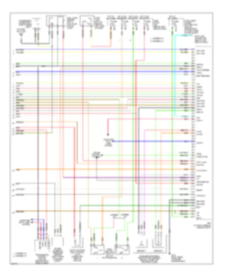
3.5L 3.5L, Engine Performance Wiring Diagram (1 of 4) for Nissan Quest S 2006 List of elements for 3.5L, Engine Performance Wiring Diagram (1 of 4) for Nissan Quest S 2006: 65 (on eng, near oil filler cap) f16 (right rear of engine compt) 02hr2 02sr2 4-speed a/t 5-speed a/t A/f sns 1 A/f-h2 A/f-ip2 A/f-un1 A/f-vm1 A/f-vm2 Af-h1 Avcc Avcc pdpres Avcc2 C-vtc l C-vtc r Camshaft position sensor (phase) (bank 1) (top right front of engine) Camshaft position sensor (phase) (bank 2) (left rear of engine) Combination meter Computer data lines system Condenser 1 (right front of engine compt) Crankshaft position sensor (pos) (at rear of engine) Ecm (right rear of engine compt) Egr volume control valve (left rear of engine compt) Egrts Enmn 1 Enmn 2 Erg 1 Erg 2 Erg 3 Erg 4 Evap Evap canister purge volume control solenoid valve (right rear of engine) Ftprs Fuel injector Gnd Ign 5 sig Inj 1 ctrl Inj 2 ctrl Inj 3 ctrl Inj 4 ctrl Inj 5 ctrl Inj 6 ctrl Knk1 Knock sensor (top front of engine) Malfunction indicator lamp Nca O2hr1 Phase lh Phase rh Pnk Pnk/red Pos Pspres Qa+ Red Refrigerant pressure sensor (right front of engine compt) Tc mtr (close) Tc mtr (open) Tc rly pwr Tps 1 Unified meter control unit Vias ctrl sol 3.5L, Engine Performance Wiring Diagram (2 of 4) for Nissan Quest S 2006 List of elements for 3.5L, Engine Performance Wiring Diagram (2 of 4) for Nissan Quest S 2006: 28 (on engine, near oil filler cap) E121 E122 E124 E9 (right rear of engine compt) Ecm relay Electric throttle control actuator (left rear of engine compt) F16 F50 Fuel pump relay Fuse 15a Hot at all times Hot in on or start Ignition coil 1 (w/ power transistor) Ignition coil 2 (w/ power transistor) Ignition coil 3 (w/ power transistor) Ignition coil 4 (w/ power transistor) Ignition coil 5 (w/ power transistor) Ignition coil 6 (w/ power transistor) Intelligent power distribution module engine room (at right side of eng compt) Nca Pnk Red Spark plug Throttle control motor Throttle control motor relay Throttle position (tp) sensor 1 Throttle position (tp) sensor 2 3.5L, Engine Performance Wiring Diagram (3 of 4) for Nissan Quest S 2006 List of elements for 3.5L, Engine Performance Wiring Diagram (3 of 4) for Nissan Quest S 2006: 19 (left front of engine) vias control solenoid valve (left side of engine compt) (under right rear of vehicle) evap control system pressure sensor Air fuel ratio sensor 1 (bank 1) (right rear of engine compt) Air fuel ratio sensor 1 (bank 2) (at front of engine) E30 Egr temperature sensor (left front of engine compt) Engine coolant temperature sensor (on left rear of engine) Front electronic controlled engine mount Fuse 15a Fuse block (j/b) (behind left side of dash) Heated oxygen sensor 2 (bank 1) (left rear of engine) Heated oxygen sensor 2 (bank 2) (right rear of engine) Hot at all times Intake valve timing control solenoid valve (bank 1) (right front of engine) Intake valve timing control solenoid valve (bank 2) (left front of engine) Mass airflow (maf) sensor Pnk Red 3.5L, Engine Performance Wiring Diagram (4 of 4) for Nissan Quest S 2006 List of elements for 3.5L, Engine Performance Wiring Diagram (4 of 4) for Nissan Quest S 2006: 68 (at right b pillar) b117 4-speed a/t 4-speed a/t 5-speed a/t 5-speed a/t A/f-ia1 A/f-ia2 A/f-un2 Accelerator pedal position (app) sensor 1 (behind lower left center of dash) Aps1 Aps2 Ascd brk sw Ascd st sw Avcc Avcc pspres Avcc2 Batt Can h Can l Can-h1 Can-l1 Cdcv Computer data lines system Condenser 2 (under right side of rear seat) Cruise control system Data link connector (below left side of dash) Dlc E124 E133 (right rear of engine compartment) E30 Ecm (at right rear of engine compt) Ecm gnd Evap canister vent control valve (under left rear of vehicle) F pmp rly Fuel level sensor unit & fuel pump (in fuel tank) Fuse 10a Fuse 15a Fuse block (j/b) (behind left side of dash) Gnd Gnd a Gnd a2 Gnd-a2 Hot at all times Hot in on or start Ign 1 sig Ign 2 sig Ign 3 sig Ign 4 sig Ign 6 sig Ign sw Intelligent power distribution module engine room (at right side of eng compt) O2sr1 Park/ neutral position switch (on transaxle) Pnk Pnp p/n Power steering pressure sensor (right rear of engine compt) P_n_sw Red Ref pres sns Sen gnd Sensor 1 Sensor 2 Ssoff Stop lamp switch (behind left side of dash) Stp lp sw Tc mtr rly Tps 2 Transmission control module (behind right side of dash)
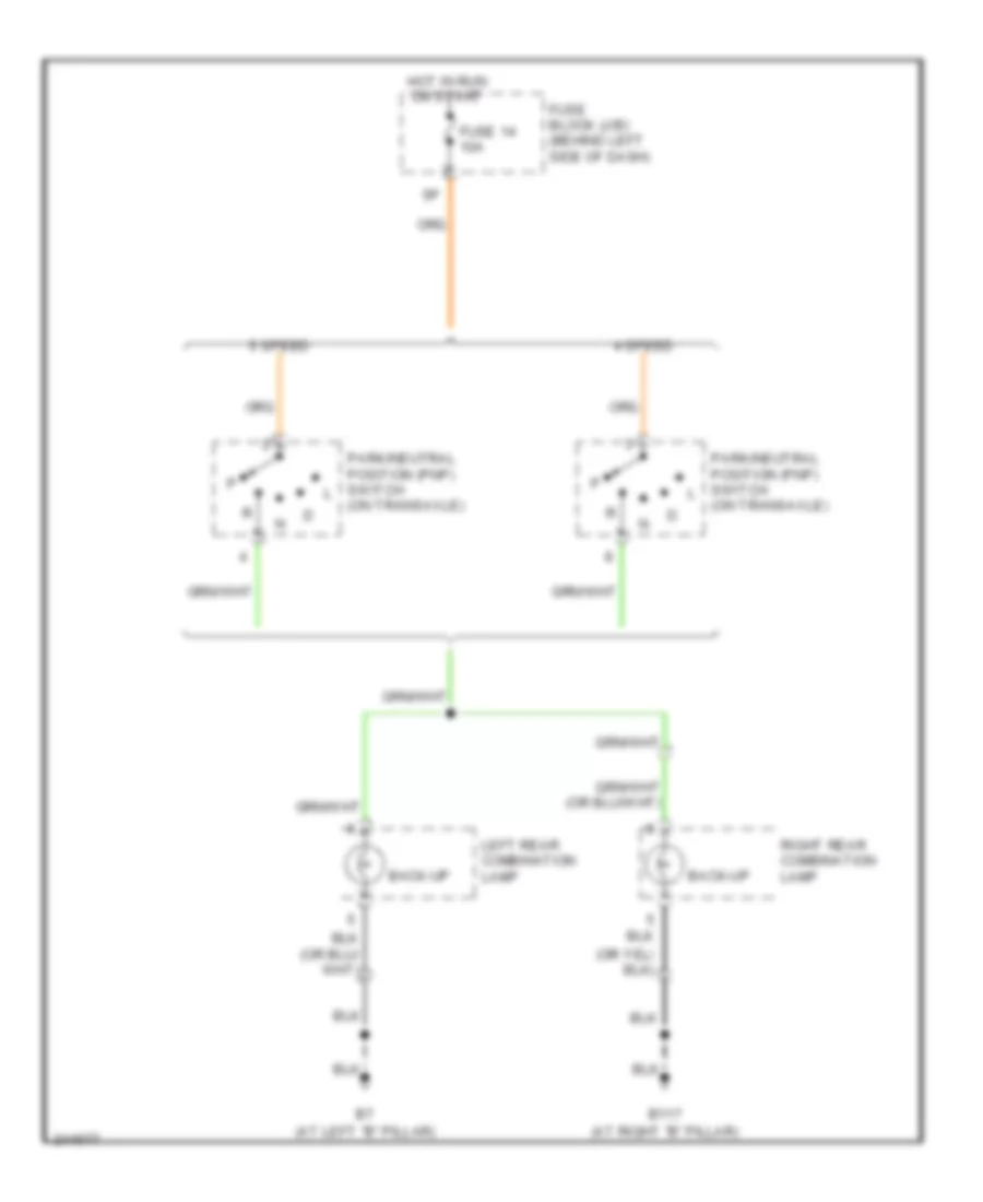
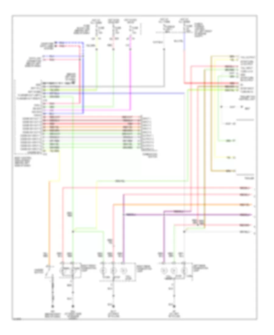
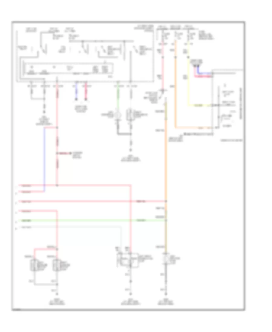
EXTERIOR LIGHTS Back-up Lamps Wiring Diagram for Nissan Quest S 2006 List of elements for Back-up Lamps Wiring Diagram for Nissan Quest S 2006: 12 (at left "b" pillar) (at right "b" pillar) 4 speed 5 speed B117 Back-up Fuse 14 10a Fuse block (j/b) (behind left side of dash) Hot in run or start Left rear combination lamp Park/neutral position (pnp) switch (on transaxle) Right rear combination lamp Exterior Lamps Wiring Diagram (1 of 2) for Nissan Quest S 2006 List of elements for Exterior Lamps Wiring Diagram (1 of 2) for Nissan Quest S 2006: 72 (behind left end of dash) m57 13p Acc sw B117 (at right "b" pillar) B307 B7 (at left "b" pillar) Bat (f/l) Bat (fuse) Body control module (bcm) (behind left side of dash) Can-h Can-l Combi sw input 1 Combi sw input 2 Combi sw input 3 Combi sw input 4 Combi sw input 5 Combi sw out 1 Combi sw out 2 Combi sw out 3 Combi sw out 4 Combi sw out 5 Combination switch Computer data lines system Data link connector (below left side of dash) E24 (at right side of engine compt) E30 Flasher out (left) Flasher out (right) Fuse & fusible link box (at left front of engine compt) Fuse 10a Fuse 15a Fuse 20a Fuse block (j/b) (behind left side of dash) Fusible link j 50a Gnd Hazard sw Hazard switch Hot at all times Hot in acc or on Hot in on or start Ign sw Input 1 Input 2 Input 3 Input 4 Input 5 Left rear combination lamp M18 M19 M61 (behind right end of dash) Output 1 Output 2 Output 3 Output 4 Output 5 Park Pnk Red Right front combination lamp Right rear combination lamp Stop Stop input Stop/turn lh output Stop/turn rh output Tail input Tail output Tail/ stop Trailer Trailer tow control unit Turn Turn lh in Turn rh in Exterior Lamps Wiring Diagram (2 of 2) for Nissan Quest S 2006 List of elements for Exterior Lamps Wiring Diagram (2 of 2) for Nissan Quest S 2006: 46 (at right side of engine compt) ipdm e/r +ig Buzzer Can-h Can-l Combination meter Computer data lines system Cpu D403 (at top left rear of roof) E121 E122 E124 E15 (at left side of engine compt) E24 (at right side of engine compt) E30 Fuse 10a Fuse 15a Fuse 34 15a Fuse 41 15a Fuse block (j/b) (behind left side of dash) Gnd (power) Gnd (signal) High mounted stop lamp Hot at all times Hot in on or start Ignition relay Interior lights system Left corn lamp Left cornering lamp Left cornering lamp relay Left front combination lamp Left license plate lamp Left turn ind M57 (behind left end of dash) Park Pnk Right corn lamp Right cornering lamp Right cornering lamp relay Right license plate lamp Right turn ind Stop lamp switch (behind left side of dash) Tail lamp relay Tail/l rly Turn Unified meter control unit
GROUND DISTRIBUTION Ground Distribution Wiring Diagram (1 of 2) for Nissan Quest S 2006 List of elements for Ground Distribution Wiring Diagram (1 of 2) for Nissan Quest S 2006: 22 B117 (at right "b" pillar) B132 (at top of right "d" pillar) B19 (at left "d" pillar) B7 (at left "b" pillar) Combination meter, front power socket 2 (console), automatic drive positioner control unit, display unit (w/o navi), display unit (w/ navi), display control unit (w/ navi), av switch, bose speaker amp, right power window, door lock/unlock switch, right door mirror & door mirror remote control switch (w/ automatic) Crankshaft position sensor, camshaft position sensor (phase) (bank 2), camshaft position sensor (phase) (bank 1), knock sensor, electric throttle control actuator (throttle position sensor) (shield wire) & ecm E15 (at left side of engine compt) E24 (at right side of engine compt) E9 (at right rear of engine compt) F16 (on engine, near oil filler cap) F9 (on engine, near oil filler cap) Fuse block (j/b) (rear blower motor relay), illumination control switch, tcs off switch (w/o vdc), vdc off switch (w/ vdc), door mirror remote control switch, console lamp, data link connector, combination switch, a/t device (overdrive control switch) (4a/t), steering angle sensor, front rear blower switch, lamps on demand switch, rear sonar system off switch, seat memory switch, fuel lid opener switch, main power window & door lock/unlock switch, left door mirror, left front door key cylinder switch, left vanity lamp, sunroof motor, left 2nd row personal lamp (w/o rear roof console assembly), right 2nd row personal lamp (w/o rear roof console assembly), right vanity lamp, room/map lamp, automatic door main switch, cargo lamp, left 3rd row personal lamp (w/o rear roof console assembly, right 3rd row personal lamp (w/o rear roof console assembly), auto anti-dazzling inside mirror, 2nd row personal lamp (w/ rear roof console assembly) & 3rd row personal lamp (w/ rear roof console assembly) Heated seat relay, right seat belt buckle switch, right heated seat switch, right rear combination lamp (w/ trailer tow) right rear combination lamp (w/o trailer tow) condenser 2, right sliding door open/close switch, rear air control, right sliding door control unit, fuel level sensor unit & fuel pump, right power seat switch, right front seat heater, dvd player, navi control unit (illumination), navi control unit, occupant detection system control unit & rear view camera control unit Ignition coil 2 (w/ power transistor), ignition coil 4 (w/ power transistor), ignition coil 6 (w/ power transistor), condenser 1, ignition coil 1 (w/ power transistor), ignition coil 3 (w/ power transistor), & ignition coil 5 (w/ power transistor), Left right front combination lamp, right front combination lamp (low), right front combination lamp (high), brake fluid level switch, front wiper motor, left cornering lamp, left front combination lamp (low), left front combination lamp (high) (w/o dtrl), right front fog lamp, left front fog lamp, daytime light control unit, daytime light relay & front blower motor relay Left seat belt buckle switch, pedal adjusting switch, rear audio remote control unit, fuel lid opener actuator, left & right rear combination lamp (w/ trailer tow), rear power socket (2nd row), rear power socket (cargo), sonar control unit, left sliding door open/close switch, fuel door interlock switch, back door close switch, left front heated seat switch, driver seat control unit, left power seat switch (w/ memory), left power seat switch (w/o memory) & left front seat heater M57 (behind left end of dash) M61 (behind right end of dash) M79 (behind right end of dash) Pedal adjusting control unit, bcm, nats antenna amplifier, data link connector, a/t device (shift lock & detent switch), air bag diagnosis sensor unit, automatic drive positioner control unit, front air control, hazard switch, glove box lamp, variable blower control & front power socket 1 (console) Subwoofer back door control unit, back door close switch, back door control unit (shield wire), driver seat control unit & left sliding door control unit Washer fluid level switch, right front combination lamp, cooling fan motor 1, ipdm e/r, right cornering lamp, heater pump, tcm (5 a/t), turbine revolution sensor (5a/t) (shield wire), revolution sensor (5a/t) (shield wire) & yaw rate/side/decel g-sensor (shield wire) Ground Distribution Wiring Diagram (2 of 2) for Nissan Quest S 2006 List of elements for Ground Distribution Wiring Diagram (2 of 2) for Nissan Quest S 2006: 18 A/t device (5 a/t), tcm (4 a/t), ecm & park neutral position switch (5 a/t) Abs actuator & electric unit (control unit) (w/o vdc) & abs actuator & electric unit (control unit) (w/ vdc) B66 (at left rear corner of vehicle) B67 (behind left rear quarterpanel) Back door control unit (shield wire), condenser 3 & condenser 4 Back door latch (shield) back door latch & rear window defogger Crash zone sensor (shield wire) D403 (at top left rear of roof) D404 (at top left rear of roof) E116 (at right side of engine compt) E126 (at right rear of engine compt) E133 E14 (at left side of engine compt) G71 Generator High mounted stop lamp, rear wiper motor, right license plate lamp, left license plate lamp, back door handle switch, back door latch, back door switch & rear view camera Left rear side curtain air bag module (shied), Left sliding door control unit
HEADLIGHTS Autolamps Wiring Diagram, with DRL (1 of 2) for Nissan Quest S 2006 List of elements for Autolamps Wiring Diagram, with DRL (1 of 2) for Nissan Quest S 2006: 71 2n m3 Acc Back door latch (at lower center of back door) Back door switch (at lower center of back door) Bat (f/l) Bat (fuse) Body control module (bcm) (behind left side of dash) Can-h Can-l Comb sw in 1 Comb sw in 2 Comb sw in 3 Comb sw in 4 Comb sw in 5 Comb sw out 1 Comb sw out 2 Comb sw out 3 Comb sw out 4 Comb sw out 5 Combination meter Combination switch Computer data lines system D403 (at top left rear of roof) Diode 1 (behind left side of dash) Door lift gate Door sw (as) Door sw (dr) Door sw (rl) Door sw (rr) E30 1q E30 5q Fuse & fusible link block (at left front of engine compt) Fuse 10a Fuse 15a Fuse block (j/b) (behind left side of dash) Fusible link j 50a Gnd High beam indicator Hot at all times Hot in acc or on Hot in on or start Hot in start Ign sw Input 1 Input 2 Input 3 Input 4 Input 5 Left front door switch (at left "b" pillar) Left sliding door switch (at left "c" pillar) M18 M19 M20 M23 M4 13p M61 (behind right end of dash) Optical sensor (at top of right side of dash) Output 1 Output 2 Output 3 Output 4 Output 5 Pnk Red Right front door switch (at right "b" pillar) Right sliding door switch (at right "c" pillar) Sensor gnd Sensor in Sig out W/ power back door W/o power back door Autolamps Wiring Diagram, with DRL (2 of 2) for Nissan Quest S 2006 List of elements for Autolamps Wiring Diagram, with DRL (2 of 2) for Nissan Quest S 2006: 45 Alt Can-h Can-l Computer data lines system Cpu Daytime light control unit (at left side of engine compt) Daytime light relay (at left side of engine compt) Diode 3 (behind left end of dash) E103 E104 E121 E122 E124 E15 (at left side of engine compt) E24 (at right side of engine compt) Fr fog Front fog lamp relay Fuse 10a Fuse 15a Gnd Gnd (power) Gnd (signal) H/l l h fuse H/l l hi gnd H/l l hi pwr H/l lh lo H/l r h fuse H/lp hi H/lp lo Headlamp high relay Headlamp low relay Hot at all times Ignition Intelligent power distribution module engine room (ipdm e/r) (at right side of engine compt) Left front fog light Left headlamp (high) Left headlamp (low) Parking brake switch (behind left end of dash) Pkb switch Pnk Right front fog light Right headlamp (high) Right headlamp (low) St sig Starting/ charging system Autolamps Wiring Diagram, without DRL (1 of 2) for Nissan Quest S 2006 List of elements for Autolamps Wiring Diagram, without DRL (1 of 2) for Nissan Quest S 2006: 67 Acc Back door latch (at lower center of back door) Back door switch (at lower center of back door) Bat (f/l) Bat (fuse) Body control module (bcm) (behind left side of dash) Can-h Can-l Comb sw in 1 Comb sw in 2 Comb sw in 3 Comb sw in 4 Comb sw in 5 Comb sw out 1 Comb sw out 2 Comb sw out 3 Comb sw out 4 Comb sw out 5 Combination meter Combination switch Computer data lines system D403 (at top left rear of roof) Door lift gate Door sw (as) Door sw (dr) Door sw (rl) Door sw (rr) E30 5q Fuse & fusible link block (at left front of engine compt) Fuse 10a Fuse 15a Fuse block (j/b) (behind left side of dash) Fusible link j 50a Gnd High beam indicator Hot at all times Hot in acc or on Hot in on or start Ign sw Input 1 Input 2 Input 3 Input 4 Input 5 Left front door switch (at left "b" pillar) Left sliding door switch (at left "c" pillar) M18 M19 M20 M23 M4 13p M61 (behind right end of dash) Optical sensor (at top of right side of dash) Output 1 Output 2 Output 3 Output 4 Output 5 Pnk Red Right front door switch (at right "b" pillar) Right sliding door switch (at right "c" pillar) Sensor gnd Sensor in Sig out W/ power back door W/o power back door Autolamps Wiring Diagram, without DRL (2 of 2) for Nissan Quest S 2006 List of elements for Autolamps Wiring Diagram, without DRL (2 of 2) for Nissan Quest S 2006: 28 Can-h Can-l Computer data lines system Cpu E121 E122 E124 E15 (at left side of engine compt) E24 (at right side of engine compt) Fr fog Front fog lamp relay Fuse 10a Fuse 15a Gnd (power) Gnd (signal) H/lp hi H/lp lo Headlamp high relay Headlamp low relay Hot at all times Intelligent power distribution module engine room (ipdm e/r) (at right side of engine compt) Left front fog light Left headlamp (high) Left headlamp (low) Pnk Right front fog light Right headlamp (high) Right headlamp (low) Headlamps Wiring Diagram, with DRL (1 of 2) for Nissan Quest S 2006 List of elements for Headlamps Wiring Diagram, with DRL (1 of 2) for Nissan Quest S 2006: 52 2n m3 Acc Bat (f/l) Bat (fuse) Body control module (bcm) (behind left side of dash) Can-h Can-l Comb sw in 1 Comb sw in 2 Comb sw in 3 Comb sw in 4 Comb sw in 5 Comb sw out 1 Comb sw out 2 Comb sw out 3 Comb sw out 4 Comb sw out 5 Combination meter Combination switch Computer data lines system Diode 1 (behind left side of dash) E30 1q E30 5q Fuse & fusible link block (at left front of engine compt) Fuse 10a Fuse 15a Fuse block (j/b) (behind left side of dash) Fusible link j 50a Gnd High beam indicator Hot at all times Hot in acc or on Hot in on or start Hot in start Ign sw Input 1 Input 2 Input 3 Input 4 Input 5 M18 M19 M23 M4 13p M61 (behind right end of dash) Output 1 Output 2 Output 3 Output 4 Output 5 Pnk Red Headlamps Wiring Diagram, with DRL (2 of 2) for Nissan Quest S 2006 List of elements for Headlamps Wiring Diagram, with DRL (2 of 2) for Nissan Quest S 2006: 45 Alt Can-h Can-l Computer data lines system Cpu Daytime light control unit (at left side of engine compt) Daytime light relay (at left side of engine compt) Diode 3 (behind left end of dash) E103 E104 E121 E122 E124 E15 (at left side of engine compt) E24 (at right side of engine compt) Fr fog Front fog lamp relay Fuse 10a Fuse 15a Gnd Gnd (power) Gnd (signal) H/l l h fuse H/l l hi gnd H/l l hi pwr H/l lh lo H/l r h fuse H/lp hi H/lp lo Headlamp high relay Headlamp low relay Hot at all times Ignition Intelligent power distribution module engine room (ipdm e/r) (at right side of engine compt) Left front fog light Left headlamp (high) Left headlamp (low) Parking brake switch (behind left end of dash) Pkb switch Pnk Right front fog light Right headlamp (high) Right headlamp (low) St sig Starting/ charging system Headlamps Wiring Diagram, without DRL (1 of 2) for Nissan Quest S 2006 List of elements for Headlamps Wiring Diagram, without DRL (1 of 2) for Nissan Quest S 2006: 48 13p m4 Acc Bat (f/l) Bat (fuse) Body control module (bcm) (behind left side of dash) Can-h Can-l Comb sw in 1 Comb sw in 2 Comb sw in 3 Comb sw in 4 Comb sw in 5 Comb sw out 1 Comb sw out 2 Comb sw out 3 Comb sw out 4 Comb sw out 5 Combination meter Combination switch Computer data lines system E30 5q Fuse & fusible link block (at left front of engine compt) Fuse 10a Fuse 15a Fuse block (j/b) (behind left side of dash) Fusible link j 50a Gnd High beam indicator Hot at all times Hot in acc or on Hot in on or start Ign sw Input 1 Input 2 Input 3 Input 4 Input 5 M18 M19 M23 M61 (behind right end of dash) Output 1 Output 2 Output 3 Output 4 Output 5 Pnk Red Headlamps Wiring Diagram, without DRL (2 of 2) for Nissan Quest S 2006 List of elements for Headlamps Wiring Diagram, without DRL (2 of 2) for Nissan Quest S 2006: 28 Can-h Can-l Computer data lines system Cpu E121 E122 E124 E15 (at left side of engine compt) E24 (at right side of engine compt) Fr fog Front fog lamp relay Fuse 10a Fuse 15a Gnd (power) Gnd (signal) H/lp hi H/lp lo Headlamp high relay Headlamp low relay Hot at all times Intelligent power distribution module engine room (ipdm e/r) (at right side of engine compt) Left front fog light Left headlamp (high) Left headlamp (low) Pnk Right front fog light Right headlamp (high) Right headlamp (low)
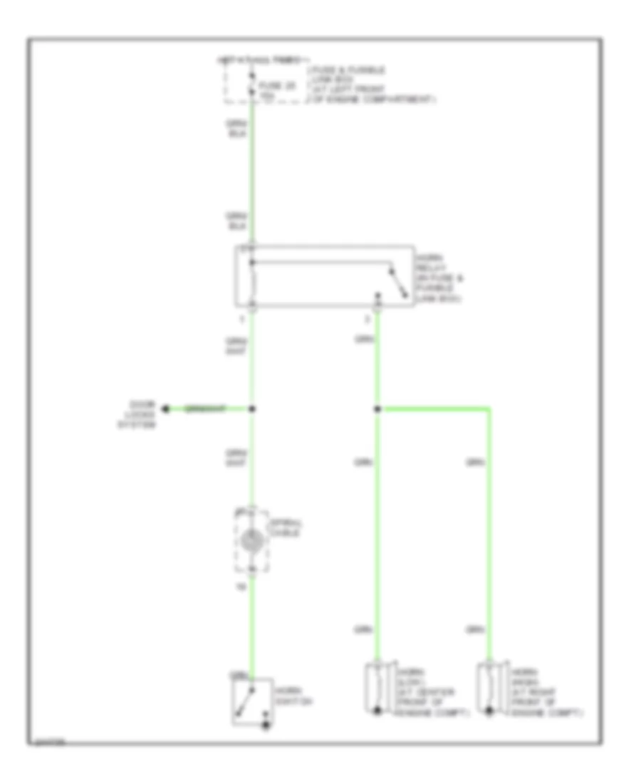
HORN Horn Wiring Diagram for Nissan Quest S 2006 List of elements for Horn Wiring Diagram for Nissan Quest S 2006: 9 Door locks system Fuse & fusible link box (at left front of engine compartment) Fuse 25 15a Horn (high) (at right front of engine compt) Horn (low) (at center front of engine compt) Horn relay (in fuse & fusible link box) Horn switch Hot at all times Spiral cable
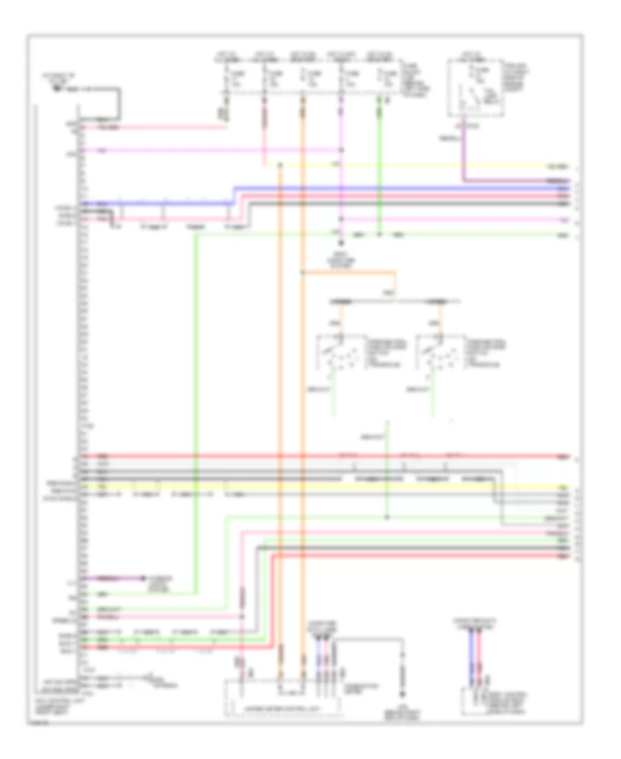
INSTRUMENT CLUSTER Instrument Cluster Wiring Diagram (1 of 2) for Nissan Quest S 2006 List of elements for Instrument Cluster Wiring Diagram (1 of 2) for Nissan Quest S 2006: 70 (4-speed a/t) (w/o vdc) 4-speed a/t A/t device o/d (4 speed off A/t) (behind center of dash) Abs ind Air bag diagnosis sensor unit (behind right end of dash) Air bag ind Anti-lock brakes system (w/ vdc) Anti-theft system B7 (at left "b" pillar) Bckl dr sw Belt ind Brake fluid level switch (at left rear of engine compt) Brake ind Buzzer Charge ind Combination meter Cruise ind Display control unit (behind right end of dash) Display unit Door ind E15 (at left side of engine compt) Fuel gauge Fuel ind Fuse 10a Fuse 15a Fuse block (j/b) (behind left side of dash) High beam ind High turn ind Hot at all times Hot in on or start Interior lights system Left turn ind M23 M24 M35 M57 (behind left end of dash) M79 (behind right end of dash) M94 Malfunction ind lamp Meter illum Navi control unit (under right front seat) O/d off Ods led Off ind Oil ind P107 Parking brake switch (behind left end of dash) Pass air bag Pnk Red Seat belt buckle switch (left side) (in driver side seat belt buckle assembly) Seat blt re Security ind Set ind Slip ind Speedometer Starting/ charging system Tachometer Tcs off ind Tire pressure ind Unified meter control unit Vdc off ind (w/ vdc) W/ navi- gation W/l W/o navi- gation Washer ind Water temp gauge Wiper/washer system Instrument Cluster Wiring Diagram (2 of 2) for Nissan Quest S 2006 List of elements for Instrument Cluster Wiring Diagram (2 of 2) for Nissan Quest S 2006: 59 (at left "b" pillar) (at right "c" pillar) (behind right side of dash) transmission control module 4 speed a/t 4-speed a/t 5 speed a/t 5-speed a/t Abs actuator & electric control unit (at right rear of engine compt) Back door switch (at lower center of back door) Body control module (behind left side of dash) Can-h Can-l Combination switch Computer data lines system D-sw D403 (at top left rear of roof) Dr sw Dr sw E121 E142 E143 E16 Engine control module (at right rear of engine compt) Fuel level sensor unit & fuel pump Gnd Input 1 Input 2 Input 3 Input 4 Input 5 Ipdm e/r (intelligent power distribution module engine room) (at right side of engine compt) L-sw & a Left front door switch Left sliding door switch (at left "c" pillar) M18 M20 Oil pressure ot switch (at right front of engine) Ops Output 1 Output 2 Output 3 Output 4 Output 5 P/warn Park/neutral position switch (on transaxle) Pnk Pwr R-sw Red Remote keyless entry receiver (behind right end of dash) Right front door switch (at right "b" pillar) Right sliding door switch Sig Spd sen 2 Tire pressure warning check connector (behind lower center of dash) W/ power back door W/ vdc W/o power back door W/o vdc
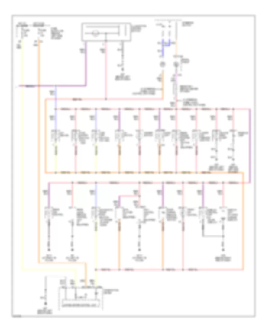
INTERIOR LIGHTS Courtesy Lamps Wiring Diagram, with Rear Roof Console Assembly (1 of 2) for Nissan Quest S 2006 List of elements for Courtesy Lamps Wiring Diagram, with Rear Roof Console Assembly (1 of 2) for Nissan Quest S 2006: 61 (at right "b" pillar) right front door switch (behind left end of dash) m57 (w/ power back door) (w/o power back door) (w/o power back door) (w/ power back door) 13p Back door switch (w/o power back door) back door latch (w/ power back door) (at lower center of back door) Bat (f/l) Bat (fuse) Bat saver Between full stroke & n Body control module (bcm) (behind left side of dash) Bus Can-h Can-l Cargo lamp Computer data lines Cpu D403 (at top left rear of roof) Door Door lift gate Door sw (as) Door sw (dr) Door sw (rl) Door sw (rr) E30 Full stroke Fuse 10a Fuse 15a Fuse & fusible link box (at left front of engine compt) Fuse block (j/b) (behind left side of dash) Fusible link j 50a Gnd Hot at all times Hot in on or start Ign sw Key ill Key switch Left foot lamp Left front door key cylinder switch (at rear of left front door) Left front door switch (at left "b" pillar) Left front step lamp Left sliding door switch (at left "c" pillar) Lock switch M18 M19 M20 M57 (behind left end of dash) M61 (behind right end of dash) Main power window & door lock/unlock switch On off Pnk Red Right foot lamp Right front step lamp Right power window & door lock/unlock switch Right sliding door switch (at right "c" pillar) Room lamp Step lamp System Unlock switch W/o rear power vent windows w/ rear power vent windows Courtesy Lamps Wiring Diagram, with Rear Roof Console Assembly (2 of 2) for Nissan Quest S 2006 List of elements for Courtesy Lamps Wiring Diagram, with Rear Roof Console Assembly (2 of 2) for Nissan Quest S 2006: 19 (behind left end of dash) m57 2nd row personal lamp 3rd row personal lamp Door Ignition keyhole illumination Lamps on demand switch Left Left door mirror (at mirror) Left vanity lamp M57 (behind left end of dash) Off Pnk Puddle lamp Right Right door mirror (at mirror) Right vanity lamp Room/map lamps Running board lamps (pre- wiring) W/ puddle lamps Courtesy Lamps Wiring Diagram, without Rear Roof Console Assembly (1 of 2) for Nissan Quest S 2006 List of elements for Courtesy Lamps Wiring Diagram, without Rear Roof Console Assembly (1 of 2) for Nissan Quest S 2006: 61 (at right "b" pillar) right front door switch (behind left end of dash) m57 (w/ power back door) (w/o power back door) (w/o power back door) (w/ power back door) 13p Back door switch (w/o power back door) back door latch (w/ power back door) (at lower center of back door) Bat (f/l) Bat (fuse) Bat saver Between full stroke & n Body control module (bcm) (behind left side of dash) Bus Can-h Can-l Cargo lamp Computer data lines Cpu D403 (at top left rear of roof) Door Door lift gate Door sw (as) Door sw (dr) Door sw (rl) Door sw (rr) E30 Full stroke Fuse 10a Fuse 15a Fuse & fusible link box (at left front of engine compt) Fuse block (j/b) (behind left side of dash) Fusible link j 50a Gnd Hot at all times Hot in on or start Ign sw Key ill Key switch Left foot lamp Left front door key cylinder switch (at rear of left front door) Left front door switch (at left "b" pillar) Left front step lamp Left sliding door switch (at left "c" pillar) Lock switch M18 M19 M20 M57 (behind left end of dash) M61 (behind right end of dash) Main power window & door lock/unlock switch Off Pnk Red Right foot lamp Right front step lamp Right power window & door lock/unlock switch Right sliding door switch (at right "c" pillar) Room lamp Step lamp System Unlock switch W/o rear power vent windows w/ rear power vent windows Courtesy Lamps Wiring Diagram, without Rear Roof Console Assembly (2 of 2) for Nissan Quest S 2006 List of elements for Courtesy Lamps Wiring Diagram, without Rear Roof Console Assembly (2 of 2) for Nissan Quest S 2006: 21 (behind left end of dash) m57 Door Ignition keyhole illumination Lamps on demand switch Left Left 2nd row personal lamp Left 3rd row personal lamp Left door mirror (at mirror) Left vanity lamp M57 (behind left end of dash) Off Pnk Puddle lamp Right Right 2nd row personal lamp Right 3rd row personal lamp Right door mirror (at mirror) Right vanity lamp Room/map lamps Running board lamps (pre- wiring) W/ puddle lamps Instrument Illumination Wiring Diagram (1 of 2) for Nissan Quest S 2006 List of elements for Instrument Illumination Wiring Diagram (1 of 2) for Nissan Quest S 2006: 68 (behind left end of dash) m57 (behind left side of dash) (w/o rear power vent windows) (w/ rear power vent windows) +ig 13p Acc sw Bat (f/l) Bat (fuse) Body control module (bcm) (behind left side of dash) Bus Can-h Can-l Comb sw in 1 Comb sw in 2 Comb sw in 3 Comb sw in 4 Comb sw in 5 Comb sw out 1 Comb sw out 2 Comb sw out 3 Comb sw out 4 Comb sw out 5 Combination switch Cpu Data link connector (below left side of dash) E121 E122 E124 E24 (at right side of engine compt) E30 Exterior lights system Fuse & fusible link box (at left front of engine compt) Fuse 10a Fuse 15a Fuse block (j/b) Fusible link j 50a Gnd Gnd (pwr) Gnd (sig) Hot at all times Hot in on or acc Hot in on or start Ign sw Ignition Input 1 Input 2 Input 3 Input 4 Input 5 Intelligent power distribution module engine room (ipdm e/r) (at right side of engine compt) M18 M19 M57 (behind left end of dash) M61 (behind right end of dash) Main power window & door lock/ unlock switch Output 1 Output 2 Output 3 Output 4 Output 5 Pnk Pwr window (bat) Pwr window (rap) Red Relay Right power window & door lock/ unlock switch Tail lamp relay Tail/l rly Instrument Illumination Wiring Diagram (2 of 2) for Nissan Quest S 2006 List of elements for Instrument Illumination Wiring Diagram (2 of 2) for Nissan Quest S 2006: 44 A/t device Audio unit Automatic door main switch (w/ power sliding door) Av switch B117 (at right "b" pillar) B7 (at left "b" pillar) Combination meter Console lamp Display control unit (w/ color display) Display unit (w/ mono- chrome display) Door mirror remote control switch Dvd player (if equipped) Front air control Fuse 10a Fuse 15a Fuse block (j/b) (behind left side of dash) Glove box lamp Gnd Hazard switch Hot at all times Hot in on or start Ill Illum Illumination control switch Lamps on demand switch M102 M23 M24 M30 M43 M57 (behind left end of dash) M79 (behind right end of dash) Navi control unit (if equipped) P106 Rear air control Rear audio remote control unit (if equipped) Rear sonar system off switch (if equipped) Resistor 1 (behind center of dash) Spiral cable Steering switch Tcs on/off switch (w/o vdc) Unified meter control unit Vdc off switch (w/ vdc) W/ steering wheel audio control switches
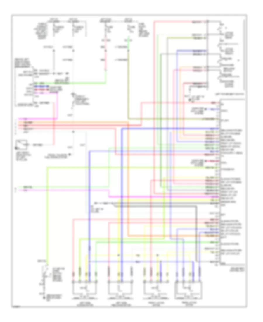
MEMORY SYSTEMS Memory Systems Wiring Diagram (1 of 3) for Nissan Quest S 2006 List of elements for Memory Systems Wiring Diagram (1 of 3) for Nissan Quest S 2006: 47 (behind right end of dash) m61 16p Address 1 Address 2 Automatic drive positioner control unit (behind left side of dash) B42 Bat Change over switch Door mirror remote control switch Fuse 10a Fuse block (j/b) (behind left side of dash) Gnd Hot at all times Hot in acc or on Ind 1 Ind 2 Interior lights system Lh mtr horiz Lh mtr vert Lh sens horiz Lh sens vert M41 M42 M57 (behind left end of dash) Mem1 Mem2 Mir sel (lh) Mir sel (rh) Mir sw dwn Mir sw lt Mir sw rt Mir sw up Mirror switch Mtr common Off Ped mtr (fr) Ped mtr (rr) Ped sens Pwr Red Rh mtr horiz Rh mtr vert Rh sens horiz Rh sens vert Seat memory switch Set Set sw Memory Systems Wiring Diagram (2 of 3) for Nissan Quest S 2006 List of elements for Memory Systems Wiring Diagram (2 of 3) for Nissan Quest S 2006: 8 (at mirror) right door mirror B7 (at left "b" pillar) Bwd Fwd Left door mirror (at mirror) Pedal adjusting motor (behind lower left center of dash) Pedal adjusting switch Red Memory Systems Wiring Diagram (3 of 3) for Nissan Quest S 2006 List of elements for Memory Systems Wiring Diagram (3 of 3) for Nissan Quest S 2006: 75 (at left "b" pillar) b7 (behind left side of dash) body control module (bcm) (behind right end of dash) m61 2n m3 A/t device (park switch) (behind center of dash) Acc sw B7 (at left "b" pillar) Backward Bat Bat (f/l) Batt Bwd Can-h Can-l Circuit breaker 2 (at left kick panel) Computer data lines system Door sw (dr) Down Driver seat control unit E30 5q Forward Front lift (down) Front lift (up) Front lifting motor Frt lift mtr (dwn) Frt lift mtr (up) Frt lift mtr sens Fuse & fusible link block (at left front of engine compt) Fuse 10a Fuse block (j/b) (behind left side of dash) Fusible link j 50a Fusible link m 40a Fwd Gnd Gnd (power) Hot at all times Hot in on or start Hot in start Ign Left front door switch (at left "b" pillar) Left power seat switch Left side reclining motor Left side sliding motor Lifting switch (front) Lifting switch (rear) M18 M19 M20 M57 (behind left end of dash) P range sw Ped sw (ff) Ped sw (rr) Pnk Rear lift (down) Rear lift (up) Rear lifting motor Recline (fr) Recline (rr) Reclining mtr (fr) Reclining mtr (rr) Reclining mtr sen Reclining switch Red Rr lift mtr (dwn) Rr lift mtr (up) Rr lift mtr sens Sensor (gnd) Slide (fr) Slide (rr) Sliding mtr (fr) Sliding mtr (rr) Sliding mtr sens Sliding switch St_sw Trunk, tailgate, fuel doors system
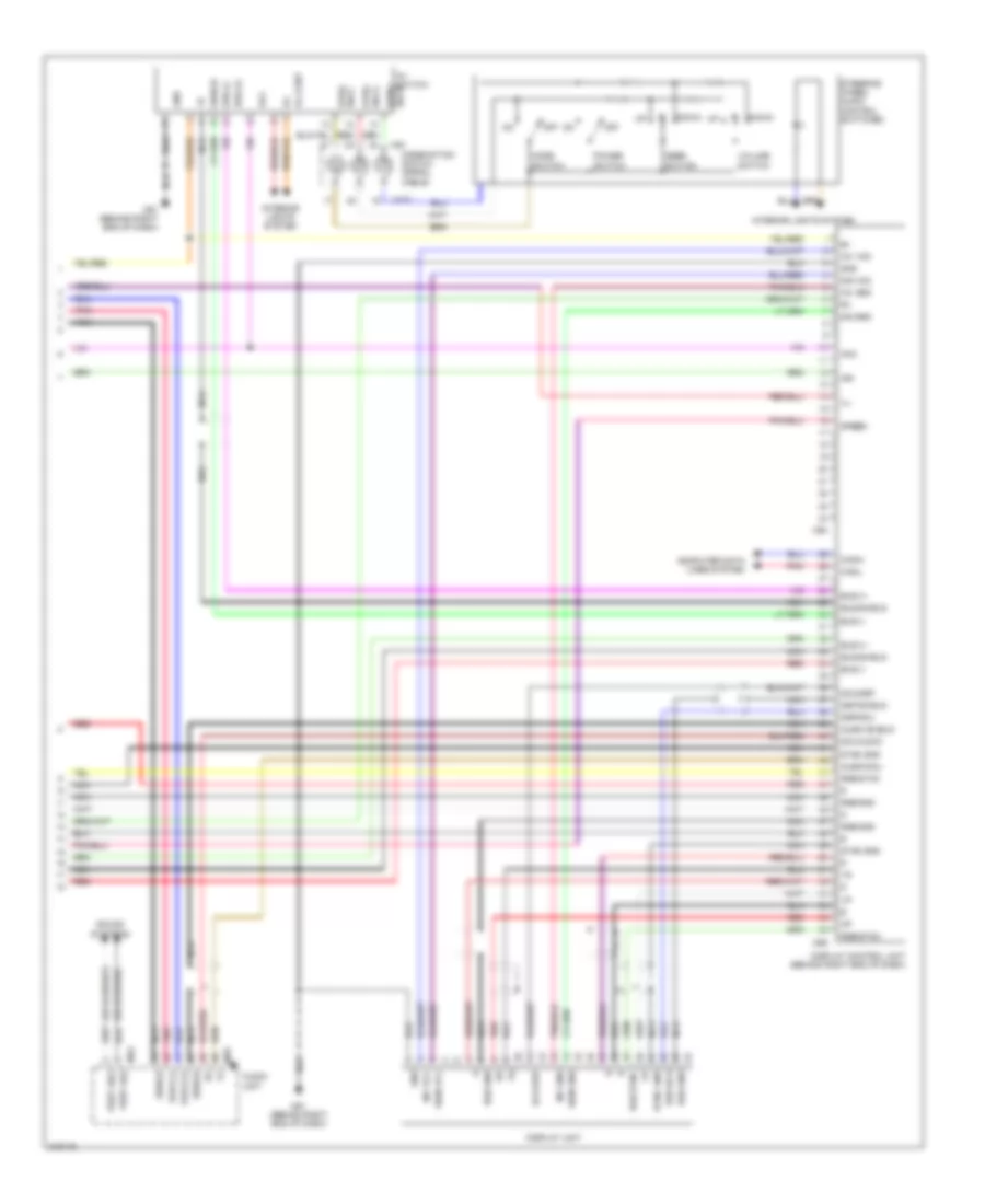
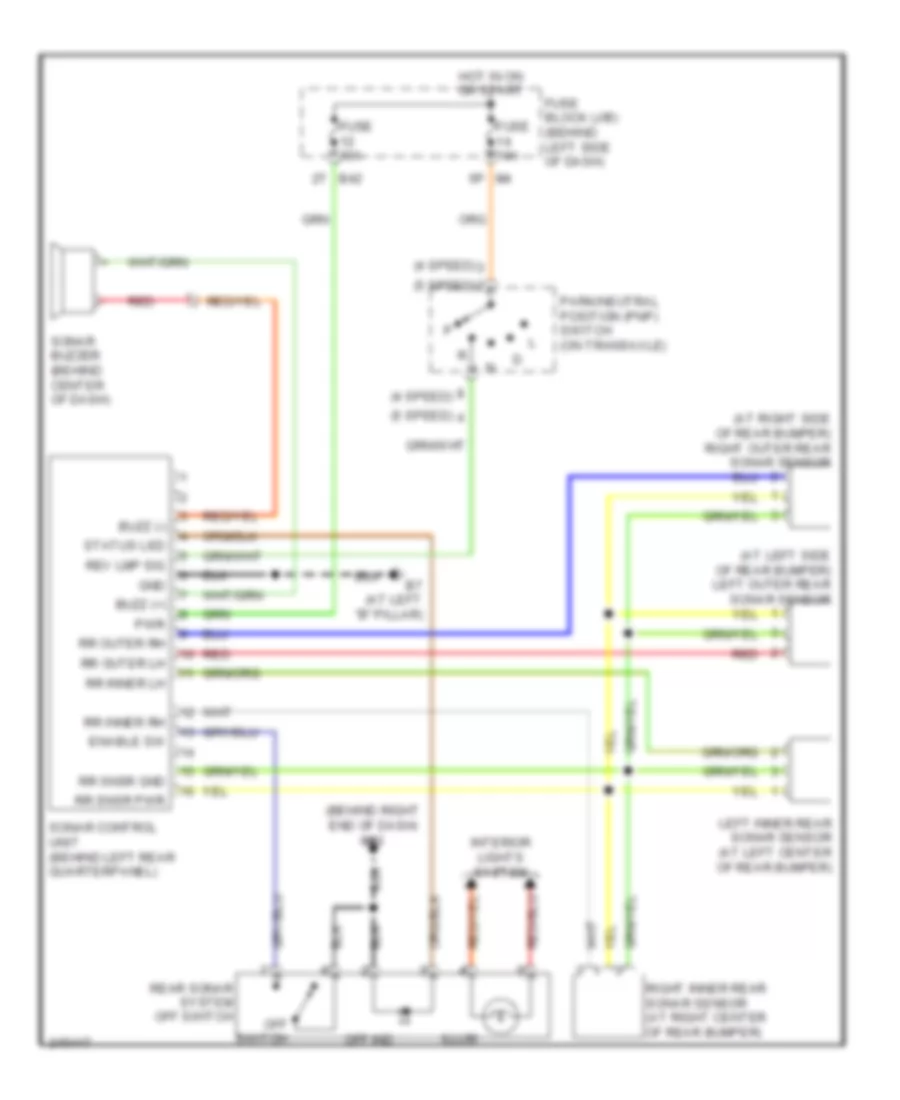
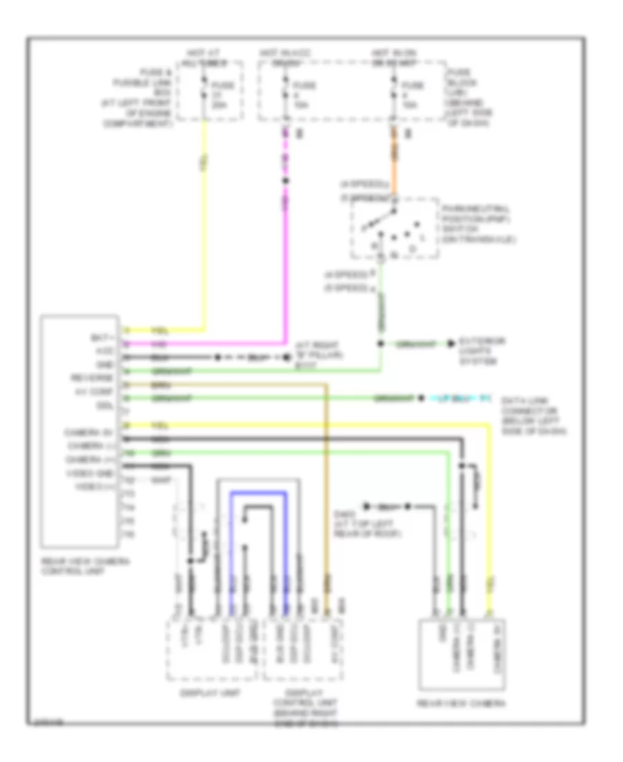
NAVIGATION Navigation Wiring Diagram (1 of 2) for Nissan Quest S 2006 List of elements for Navigation Wiring Diagram (1 of 2) for Nissan Quest S 2006: 52 (at right "b" pillar) b117 16p 16p 4 speed 4p 4p 5 speed 5p 5p 8p 8p Acc Ant gnd (gps) Ant sig (gps) Body computer system Body control module (bcm) (behind left side of dash) Bus (+) Bus (-) Can-h Can-l Combination meter Computer data lines system E122 Fuse 10a Fuse 15a Fuse block (j/b) (behind left side of dash) Gnd Gps antenna Hot at all times Hot in acc or on Hot in on or start Ign Ill+ Interior lights system Ipdm e/r (at right side of engine compt) M18 M23 M24 M79 (behind right end of dash) Navi control unit (under right front seat) Nca P106 P107 P151 Park/neutral position (pnp) switch (on transaxle) Pnk Red Rgb shield Rgb sync Shield Speed (8) Sync shield Tail lamp relay Unified meter control unit Voice (+) Voice (-) Navigation Wiring Diagram (2 of 2) for Nissan Quest S 2006 List of elements for Navigation Wiring Diagram (2 of 2) for Nissan Quest S 2006: 60 Acc Audio shield Audio unit Audio-dcu Av switch Bus (+) Bus (-) Bus gnd Bus shield Can-h Can-l Combination switch (spiral cable) Computer data lines system Dcu-audio Dcu-dsp Display control unit (behind right end of dash) Display unit Down Dsp shield Dsp-dcu Frsp lh(+) Frsp lh(-) Gnd Ign Ill Ill cont Interior lights system Inv gnd Inv vcc M102 M30 M43 M45 M61 (behind right end of dash) M94 M95 Mode switch Nca Off Pnk Power switch Red Rgb gnd Rgb sync Seek switch Shield Sig gnd Sig vcc Sign gnd Sign vcc Sound systems Speed Steering wheel audio control switches Strg sw a Strg sw c Sw b strg Sync gnd Voice (+) Voice (-) Volume switch Rear Sonar Wiring Diagram for Nissan Quest S 2006 List of elements for Rear Sonar Wiring Diagram for Nissan Quest S 2006: 35 (4 speed) (5 speed) (at left side of rear bumper) left outer rear sonar sensor (at right side of rear bumper) right outer rear sonar sensor (behind right end of dash) m61 2t b42 5p m4 B7 (at left "b" pillar) Buzz (+) Buzz (-) Enable sw Fuse 10a Fuse block (j/b) (behind left side of dash) Gnd Hot in on or start Illum Interior lights system Left inner rear sonar sensor (at left center of rear bumper) Off ind Off switch Park/neutral position (pnp) switch (on transaxle) Pwr Rear sonar system off switch Red Rev lmp sig Right inner rear sonar sensor (at right center of rear bumper) Rr inner lh Rr inner rh Rr outer lh Rr outer rh Rr snsr gnd Rr snsr pwr Sonar buzzer (behind center of dash) Sonar control unit (behind left rear quarterpanel) Status led Rear View Monitoring Wiring Diagram for Nissan Quest S 2006 List of elements for Rear View Monitoring Wiring Diagram for Nissan Quest S 2006: 37 (4 speed) (5 speed) (at right "b" pillar) b117 Acc Av cont Bat+ Bus gnd Camera (+) Camera (-) Camera 6v D403 (at top left rear of roof) Data link connector (below left side of dash) Dcu-dsp Ddl Display control unit (behind right end of dash) Display unit Dsp-dcu Exterior lights system Fuse & fusible link box (at left front of engine compartment) Fuse 10a Fuse 20a Fuse block (j/b) (behind left side of dash) Gnd Hot at all times Hot in acc or on Hot in on or start M94 M95 Nca Park/neutral position (pnp) switch (on transaxle) Rear view camera Rear view camera control unit Reverse Video (+) Video gnd Vtr+ Vtr-
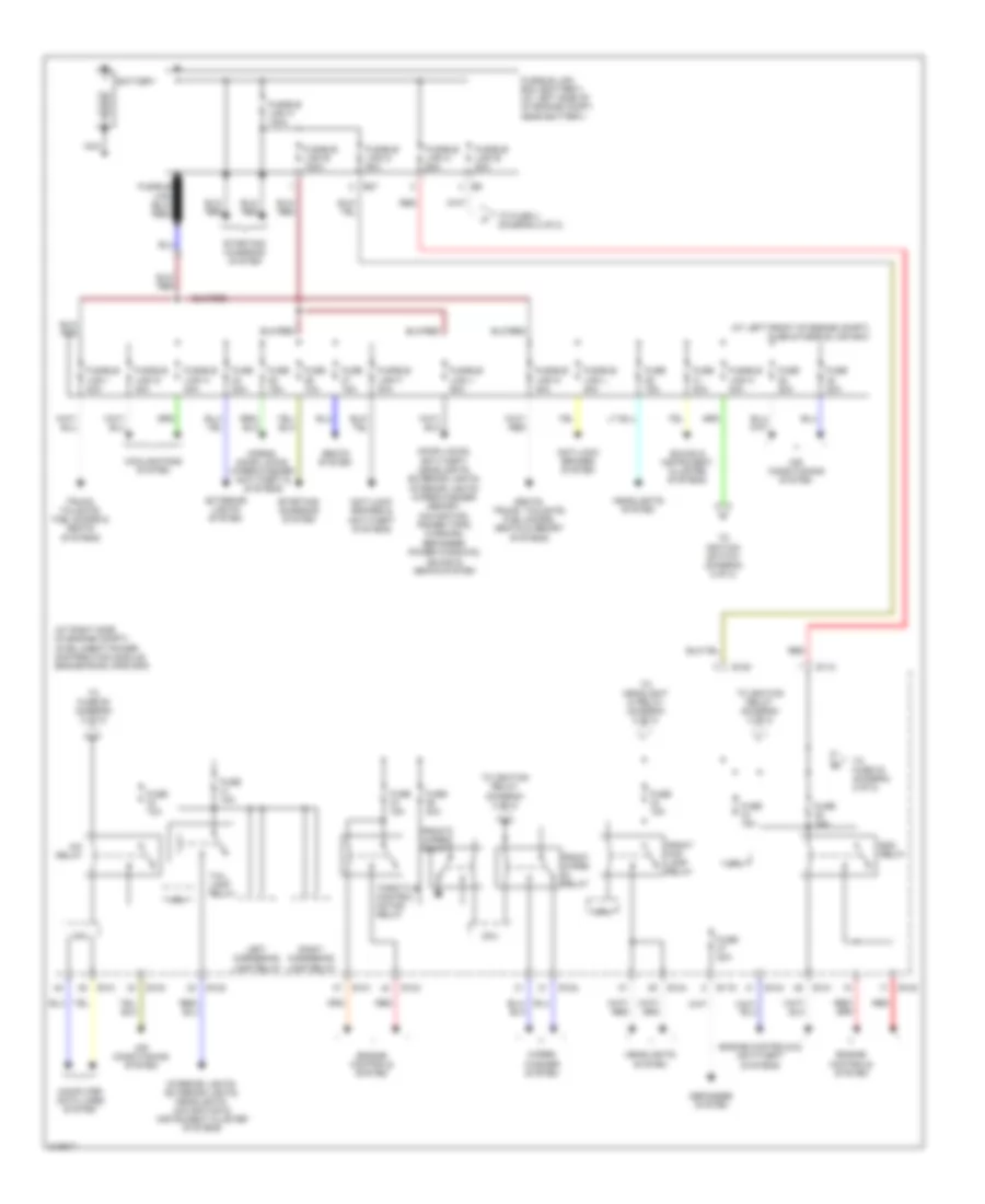
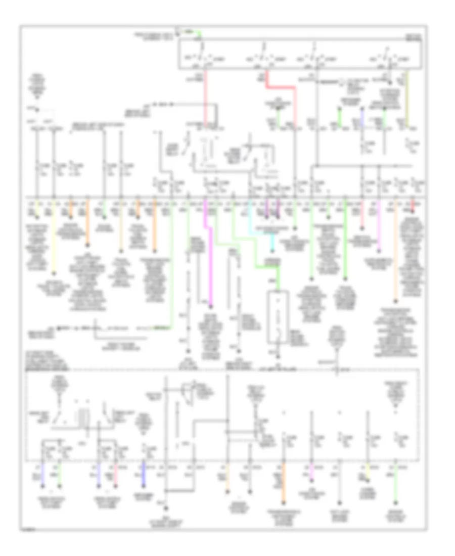
POWER DISTRIBUTION Power Distribution Wiring Diagram (1 of 2) for Nissan Quest S 2006 List of elements for Power Distribution Wiring Diagram (1 of 2) for Nissan Quest S 2006: 65 (at left front of engine compt) fuse & fusible link box (at right side of engine compt) intelligent power distribution module engine room (ipdm e/r) A/c relay Air conditioning system Anti-lock brakes & anti-theft systems Anti-lock brakes system Battery Computer data lines system Cooling fans system Cpu Defogger system Door locks, anti-theft, headlights, exterior lights, interior lights, wiper/washer, memory, navigation, power tops, warning, defogger, power windows, sound & seats system E118 E119 E120 E121 E122 E124 E27 Ecm relay Engine controls & anti-theft systems Engine controls system Exterior lights system Front fog lamp relay Front wiper hi relay Front wiper relay Fuse 10a Fuse 15a Fuse 20a Fuse 30a Fusible link a 140a Fusible link b 80a Fusible link box (battery) (at left side of of engine compt, near battery) Fusible link c 60a Fusible link d 80a Fusible link e 100a Fusible link f 40a Fusible link g 40a Fusible link h 40a Fusible link i 40a Fusible link j 50a Fusible link k 40a Fusible link l 40a Fusible link m 40a Headlights system Horns, door locks, wiper/washer, anti-theft & systems Interior lights, exterior lights, headlights, navigation & instrument cluster systems Left cornering lamp relay Nca Red Right cornering lamp relay Seats system Seats, trunk, tailgate, fuel doors, seats & memory systems Sound & instrument cluster systems Starting/ charging system Tail lamp relay Throttle control motor relay To fuse 3 (diagram 2 of 2) To fuse 32 (diagram 2 of 2) To fuse 50 (diagram 2 of 2) To headlight hi relay (diagram 2 of 2) To ignition relay (diagram 2 of 2) To ignition switch (diagram 2 of 2) Trunk, tailgate, fuel doors & seats systems Wiper/ washer system Power Distribution Wiring Diagram (2 of 2) for Nissan Quest S 2006 List of elements for Power Distribution Wiring Diagram (2 of 2) for Nissan Quest S 2006: 92 (at right side of engine compt) intelligent power distribution module engine room (ipdm e/r) (behind left end of dash) (behind left side of dash) fuse block (j/b) (diagram 1 of 2) 10p m4 12p m4 13p m4 14p 15p 16p m4 1n m3 1s e32 1t b42 2p m4 2r e31 2t b42 3n m3 3t b42 4n m3 4q e30 5p m4 5q e30 5t b42 8q e30 Acc Acce- ssory relay Air conditioning & defogger systems Air conditioning system Air conditioning, anti-theft, anti-lock brakes, engine controls, instrument cluster, exterior lights, transmissions, interior lights, navigation, sound, door locks & warning systems Anti-lock brakes system B19 (at left "d" pillar) B7 (at left "b" pillar) Cpu Defogger system E118 E119 E121 E122 E124 E24 (at right side of engine compt) E30 E30 1q E31 Engine controls & transmissions systems Engine controls system Engine controls, door locks, anti-theft, headlights, exterior lights, interior lights, seats, wiper/ washer, power tops, navigation, warning, defogger & power windows systems Engine controls, transmissions, starting/ charging, headlights & anti-lock brakes systems From a/c relay (diagram 1 of 2) From front wiper hi relay (diagram 1 of 2) From fuse 34 (diagram 1 of 2) From fuse 43 (diagram 1 of 2) From fusible link b (diagram 1 of 2) From fusible link k b From ignition switch (diagram 2 of 2) Front power socket-1 (console) Front power socket-2 (console) Fuel pump relay Fuse 10a Fuse 15a Fuse 20a Headlight high relay Headlight low relay Headlights & anti-theft systems Headlights & seats systems Ig2 red Ignition relay Ignition switch M4 7p M57 M61 (behind right end of dash) M79 (behind right end of dash) Mirrors system Navigation, exterior lights, interior lights, headlights, mirrors, door locks & anti-theft systems Off Rear blower motor relay Rear power socket (2nd row) Rear power socket (cargo) + Red Seats & transmissions systems Sound & trunk, tailgate, fuel doors system Sound systems Sound, seats, door locks, headlights, exterior lights, interior lights & power windows systems Start Starting/ charging system To ignition relay (diagram 2 of 2) Transmissions & instrument cluster systems Transmissions, anti-lock brakes, engine controls, instrument cluster, warning & exterior lights systems Transmissions, seats, sound, navigation, anti-lock brakes, engine controls & trunk, tailgate, fuel doors systems Trunk, tailgate, fuel doors & seats systems Trunk, tailgate, fuel doors, navigation & seats systems Trunk, tailgate, fuel doors, warning & defogger systems Wiper/ washer system
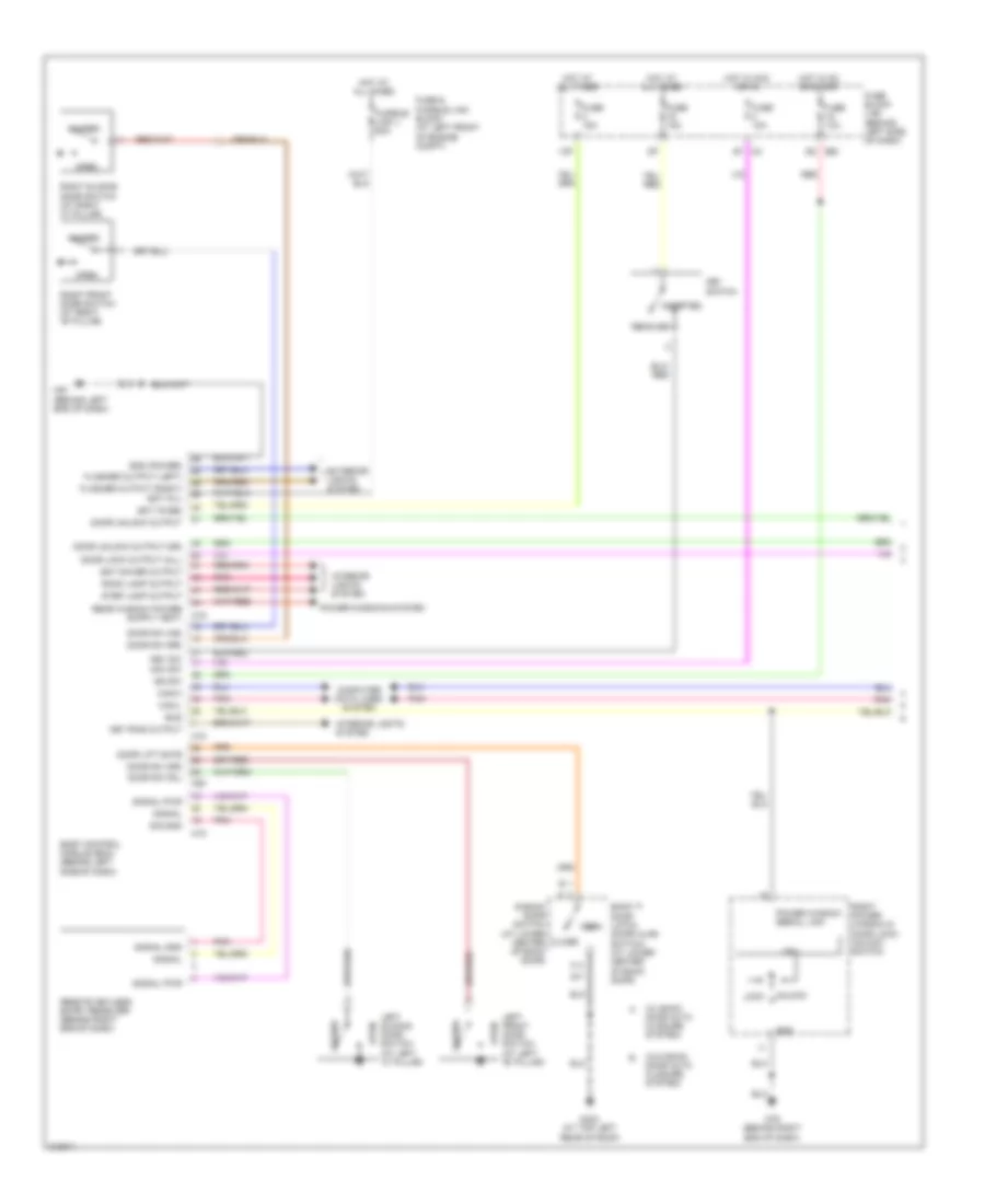
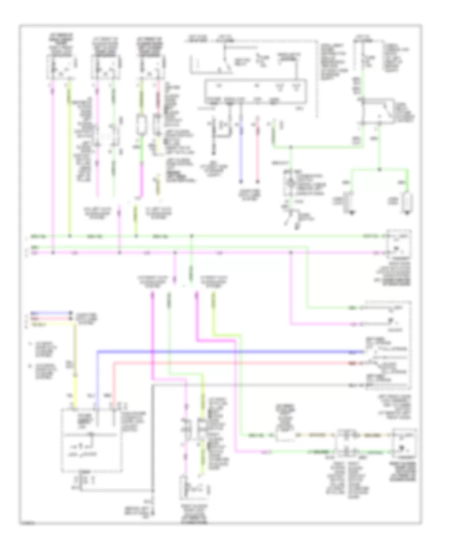
POWER DOOR LOCKS Power Door Locks Wiring Diagram (1 of 2) for Nissan Quest S 2006 List of elements for Power Door Locks Wiring Diagram (1 of 2) for Nissan Quest S 2006: 72 (w/ back door auto closure system) (w/o back door auto closure system) 13p 4p m4 Acc sw Back door latch (door ajar switch) (at lower center of back door) Back door switch (at lower center of back door) Bat (f/l) Bat (fuse) Bat saver output Body control module (bcm) (behind left side of dash) Bus Can-h Can-l Close Closed Computer data lines system Cpu D403 (at top left rear of roof) Door lift gate Door lock output (all) Door sw (as) Door sw (dr) Door sw (rl) Door sw (rr) Door unlock output Door unlock output (dr) E30 5q Exterior lights system Flasher output (left) Flasher output (right) Fuse & fusible link block (at left front of engine compt) Fuse 10a Fuse 15a Fuse block (j/b) (behind left side of dash) Fusible link j 50a Gnd Gnd (power) Hot at all times Hot in acc or on Hot in on or start Ign sw Inserted Interior lights system Key ring output Key sw Key switch Left front door switch (at left "b" pillar) Left sliding door switch (at left "c" pillar) Lock M18 M19 M20 M57 (behind left end of dash) M79 (behind right end of dash) Open Pnk Power window serial link Power windows system Red Remote keyless entry receiver (behind right end of dash) Removed Right front door switch (at right "b" pillar) Right power window & door lock/ unlock switch Right sliding door switch (at right "c" pillar) Room lamp output Sig gnd Signal Signal gnd Signal pwr Step lamp output Unlock Power Door Locks Wiring Diagram (2 of 2) for Nissan Quest S 2006 List of elements for Power Door Locks Wiring Diagram (2 of 2) for Nissan Quest S 2006: 73 (at front of (at front of sliding door) sliding door) left sliding left sliding door lock door lock actuator actuator (at front of sliding door) left sliding door lock door lock actuator actuator (at rear of (at rear of right front right front door) door) right front door lock actuator (at right "b" pillar) (pillar) right sliding b139 door contact switch (at right (at right "c" pillar) "c" pillar) right sliding door control unit (behind left end of dash) m57 (in center of sliding door) (door) left sliding d201 door contact switch (in center of sliding door) (door) left sliding door contact switch (w/ back door auto closure system) (w/o back door auto closure system) +ig A b B a B139 B57 Back door lock actuator (w/o auto sliding door system) (at lower center (at lower center of back door) of back door) Between full stroke & n C c Can h Can l Combination switch (spiral cable) (behind left Computer data lines system Contact switch (pillar) (near top of left "b" pillar) Cpu D d D201 D301 d301 D7 d8 E121 E124 E24 (at right side of engine compt) Full stroke Fuse & fusible link block (at left front of engine compt) Fuse 15a Gnd H/lp hi H/lp lo Headlights system Horn (high) Horn (low) Horn relay (in fuse & fusible link box) Horn rly Horn switch Hot at all times Hot in on or start Ignition relay Intelligent power distribution module engine room (ipdm e/r) (at right side of engine compt) Left front door lock assembly (key cylinder switch) (at rear of left front door) Left sliding door a Left sliding door contact switch (pillar) b57 (near top of left "b" pillar) Left sliding door control unit (behind (behind left rear left rear quarterpanel) Lock M m M102 M30 Main power window & door lock/ unlock switch Pnk Power Power window serial link Red Right right sliding door contact switch (door) (in center of sliding door) Right sliding door contact switch d301 (door) (in center of sliding door) Right sliding door lock actuator (at front of (at front of sliding door) sliding door) Right sliding right sliding door lock door lock actuator actuator (at front of (at front of sliding door) sliding door) Side of dash) Signal Sliding door contact switch (pillar) (at right "b" pillar) Unlock Unlock switch full stroke W/ left auto sliding door system W/ right auto sliding door system W/o left auto sliding door system W/o right auto sliding door system
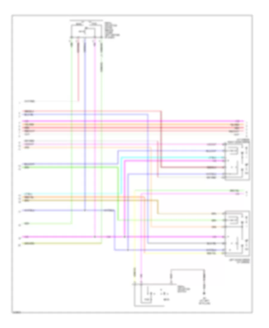
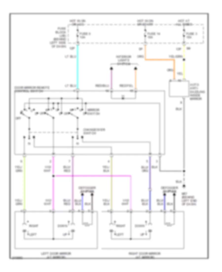
POWER MIRRORS Power Mirror Wiring Diagram for Nissan Quest S 2006 List of elements for Power Mirror Wiring Diagram for Nissan Quest S 2006: 22 12p 13p Auto anti- dazzling inside mirror Changeover switch Defogger system Door mirror remote control switch Down Fuse 14 10a Fuse 3 15a Fuse 6 10a Fuse block (j/b) (behind left side of dash) Hot at all times Hot in on or acc Hot in on or start Interior lights system Left Left door mirror (at mirror) M57 (behind left end of dash) Mirror switch Off Right Right door mirror (at mirror)
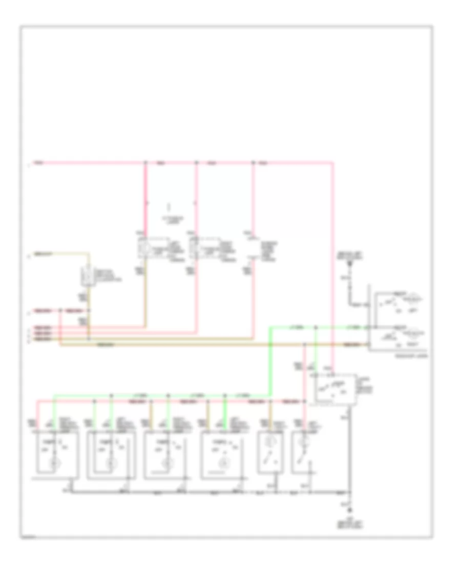
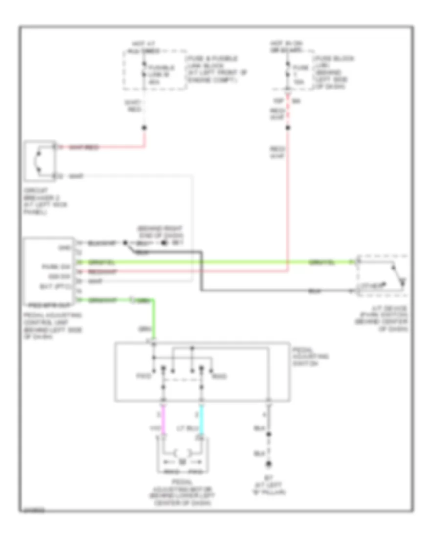
POWER SEATS Adjustable Pedal Wiring Diagram for Nissan Quest S 2006 List of elements for Adjustable Pedal Wiring Diagram for Nissan Quest S 2006: 22 (behind right end of dash) m61 15p A/t device (park switch) (behind center of dash) B7 (at left "b" pillar) Bat (ptc) Circuit breaker 2 (at left kick panel) Fuse & fusible link block (at left front of engine compt) Fuse 10a Fuse block (j/b) (behind left side of dash) Fusible link m 40a Fwd Gnd Hot at all times Hot in on or start Ign sw Other Park sw Ped mtr out Pedal adjusting control unit (behind left side of dash) Pedal adjusting motor (behind lower left center of dash) Pedal adjusting switch Rwd Heated Seats Wiring Diagram for Nissan Quest S 2006 List of elements for Heated Seats Wiring Diagram for Nissan Quest S 2006: 18 (at right "b" pillar) b117 2p m4 B117 (at right "b" pillar) B7 (at left "b" pillar) Fuse & fusible link block (at left front of engine compt) Fuse 10a Fuse 15a Fuse block (j/b) (behind left side of dash) Heated seat relay (at right kick panel) High Hot at all times Hot in on or start Left front heated seat switch Left front seat heater Low Off Right front heated seat switch Right front seat heater Power Seat Wiring Diagram for Nissan Quest S 2006 List of elements for Power Seat Wiring Diagram for Nissan Quest S 2006: 29 B117 (at right "b" pillar) B7 (at left "b" pillar) Back- ward Bwd Circuit breaker 1 (at right kick panel) Circuit breaker 2 (at left kick panel) Down Dwn For- ward Front lifting motor Front lifting switch Fuse & fusible link block (at left front of engine compt) Fusible link i 40a Fusible link m 40a Fwd Hot at all times Left front power seat Left power seat switch Left reclining motor Left sliding motor Rear lifting motor Rear lifting switch Reclining switch Red Right front power seat Right power seat switch Right reclining motor Right sliding motor Sliding switch
POWER TOP/SUNROOF Power Top/Sunroof Wiring Diagram for Nissan Quest S 2006 List of elements for Power Top/Sunroof Wiring Diagram for Nissan Quest S 2006: 31 Bat (f/l) Body control module (bcm) (behind left side of dash) Cpu Door sw (as) Door sw (dr) E30 Encoder Fuse & fusible link box (at left front of engine compartment) Fuse 10a Fuse block (j/b) (behind left side of dash) Fusible j 50a Gnd (power) Hot at all times Hot in on or start Ignition sw Left front door switch (at left "b" pillar) M18 M19 M20 M57 (behind left end of dash) Pnk Pre-select switch Pwr window (rap) Pwr wndw (bat) Red Right front door switch (at right "b" pillar) Slide limit sw Sun roof motor (at center front of roof) Sun roof switch Tilt limit sw Tilt switch
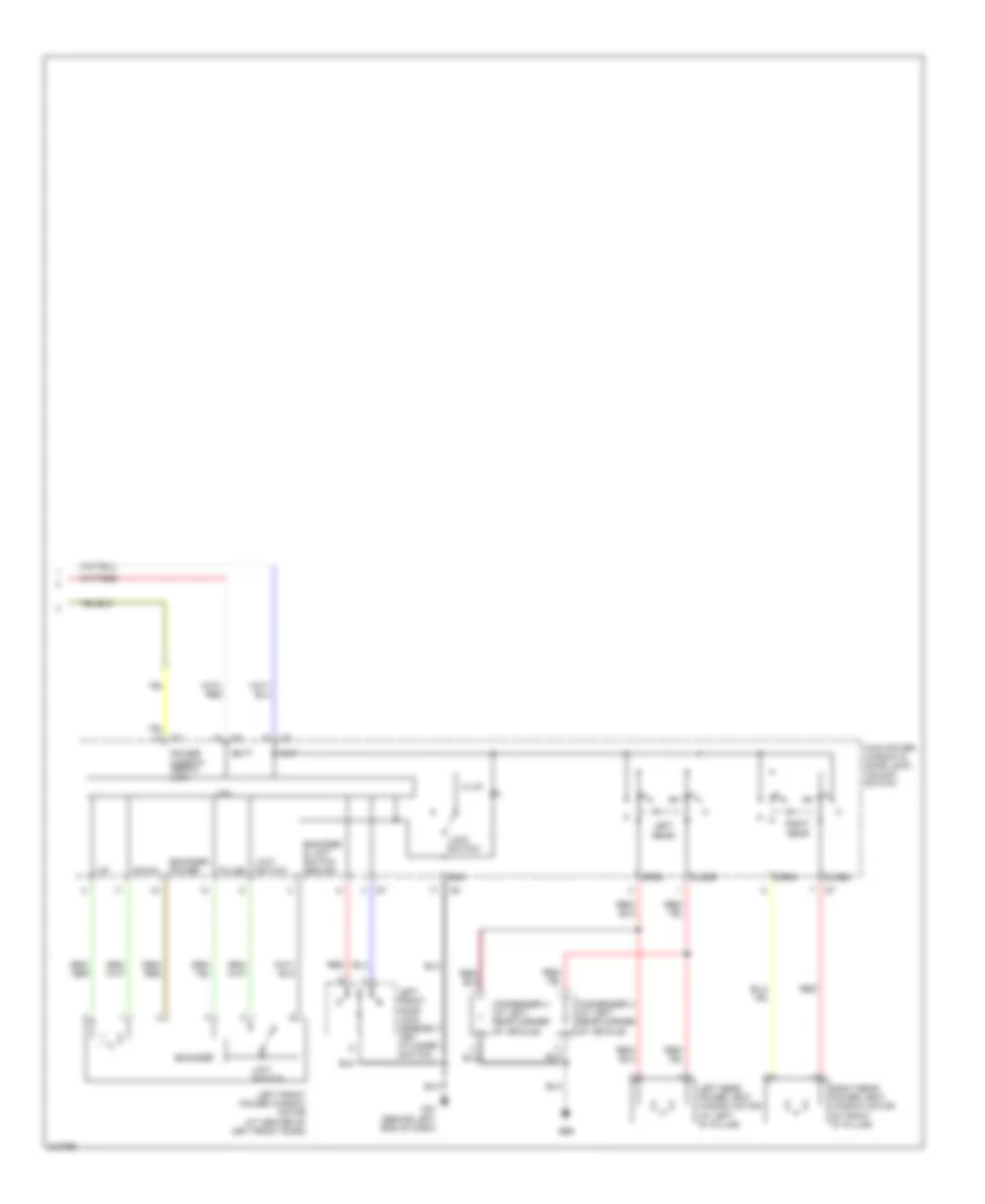
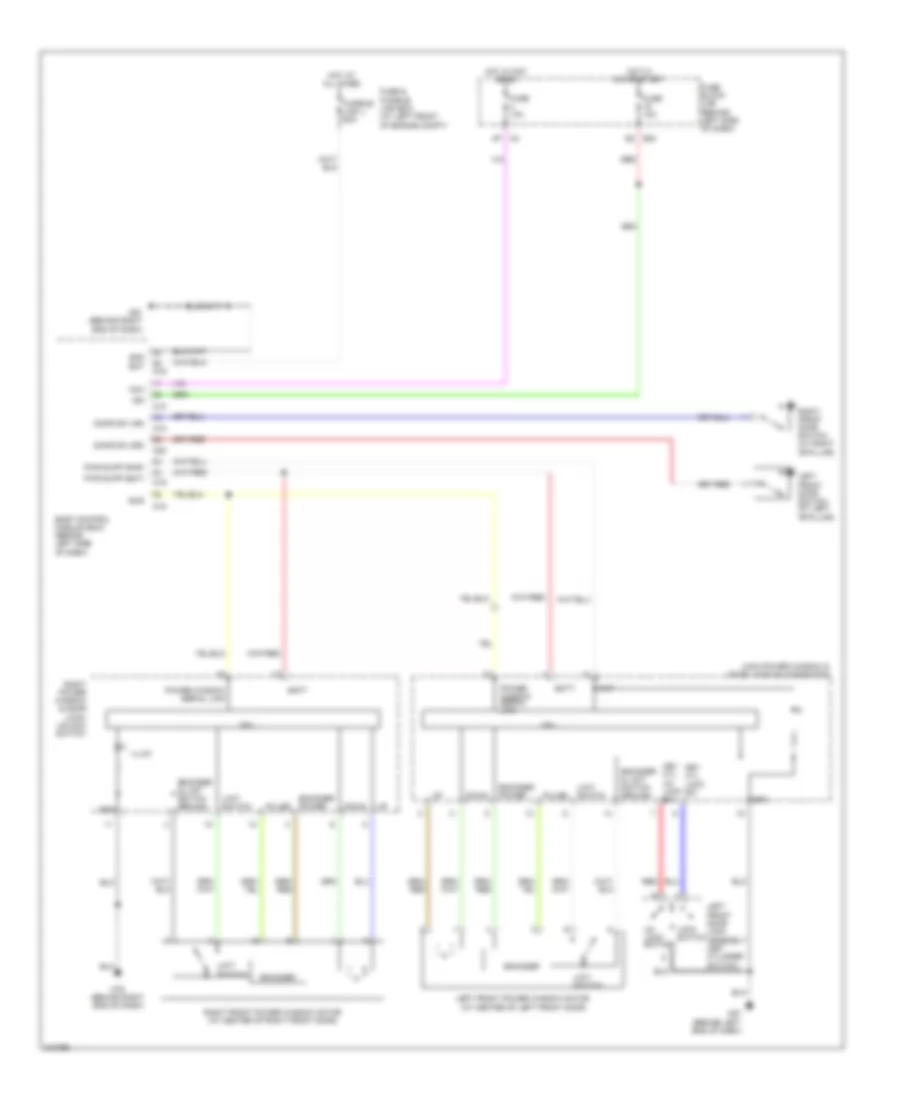
POWER WINDOWS Power Windows Wiring Diagram, with Rear Power Vent Windows (1 of 2) for Nissan Quest S 2006 List of elements for Power Windows Wiring Diagram, with Rear Power Vent Windows (1 of 2) for Nissan Quest S 2006: 42 (at center of right front door) 4p m4 5q e30 Acc Bat Batt Body control module (bcm) (behind left side of dash) Bus Closed Cpu Door sw (as) Door sw (dr) Down Encoder Encoder & limit switch ground Encoder power Fuse & fusible link box (at left front of engine compt) Fuse 10a Fuse block (j/b) (behind left side of dash) Fusible link j 50a Gnd Hot at all times Hot in acc or on Hot in on or start Ign Illum Left front door switch (at left "b" pillar) Limit switch M18 M19 M20 M61 (behind right end of dash) M79 (behind right end of dash) Open Power window serial link Pulse Pwr win pwr supp (bat) Pwr win pwr supp (rap) Red Right front door switch (at right "b" pillar) Right front power window motor Right power window & door lock/unlock switch Power Windows Wiring Diagram, with Rear Power Vent Windows (2 of 2) for Nissan Quest S 2006 List of elements for Power Windows Wiring Diagram, with Rear Power Vent Windows (2 of 2) for Nissan Quest S 2006: 27 B66 Batt Close Condenser 3 (at left rear corner of vehicle) Condenser 4 (at left rear corner of vehicle) Cpu Down Encoder Encoder & limit switch ground Encoder power Gnd Illum Left front door lock assembly (key cylinder switch) Left front power window motor (at center of left front door) Left rear Left rear power vent window motor (at left "d" pillar) Limit switch Lock switch M57 (behind left end of dash) Main power window & door lock/ unlock switch Open Power window serial link Pulse Rap Red Right rear Right rear power vent window motor (at right "d" pillar) Power Windows Wiring Diagram, without Rear Power Vent Windows for Nissan Quest S 2006 List of elements for Power Windows Wiring Diagram, without Rear Power Vent Windows for Nissan Quest S 2006: 48 4p m4 5q e30 Acc Bat Batt Body control module (bcm) (behind left side of dash) Bus Cpu Door sw (as) Door sw (dr) Down Encoder Encoder & limit switch ground Encoder power Fuse & fusible link box (at left front of engine compt) Fuse 10a Fuse block (j/b) (behind left side of dash) Fusible link j 50a Gnd Hot at all times Hot in acc or on Hot in on or start Ign Illum Key cyl lock sw Key cyl un lock sw Left front door lock assembly (key cylinder switch) Left front door switch (at left "b"pillar) Left front power window motor (at center of left front door) Limit switch Lock switch M18 M19 M20 M57 (behind left end of dash) M61 (behind right end of dash) M79 (behind right end of dash) Main power window & door lock/unlockswitch Power window serial link Pulse Pwr supp (bat) Pwr supp (rap) Rap Red Right front door switch (at right "b"pillar) Right front power window motor (at center of right front door) Right power window & door lock/ unlock switch Un lock switch
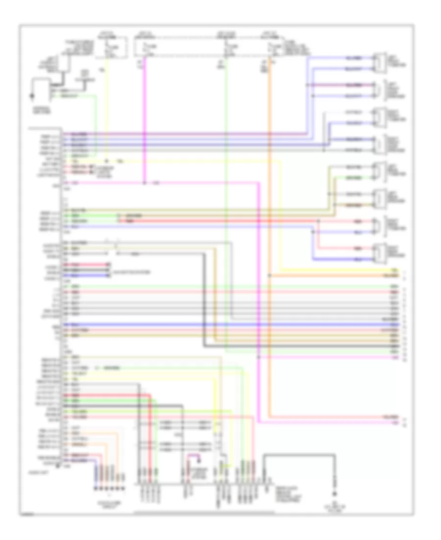
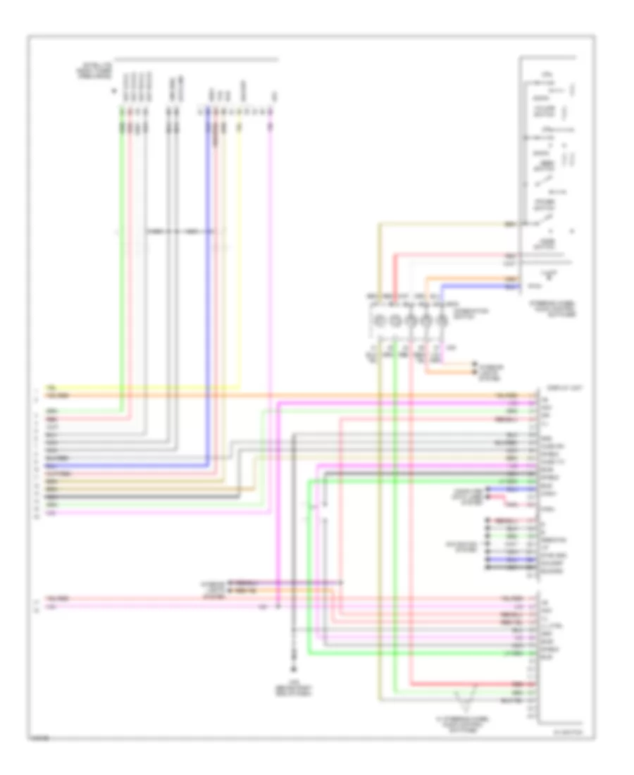
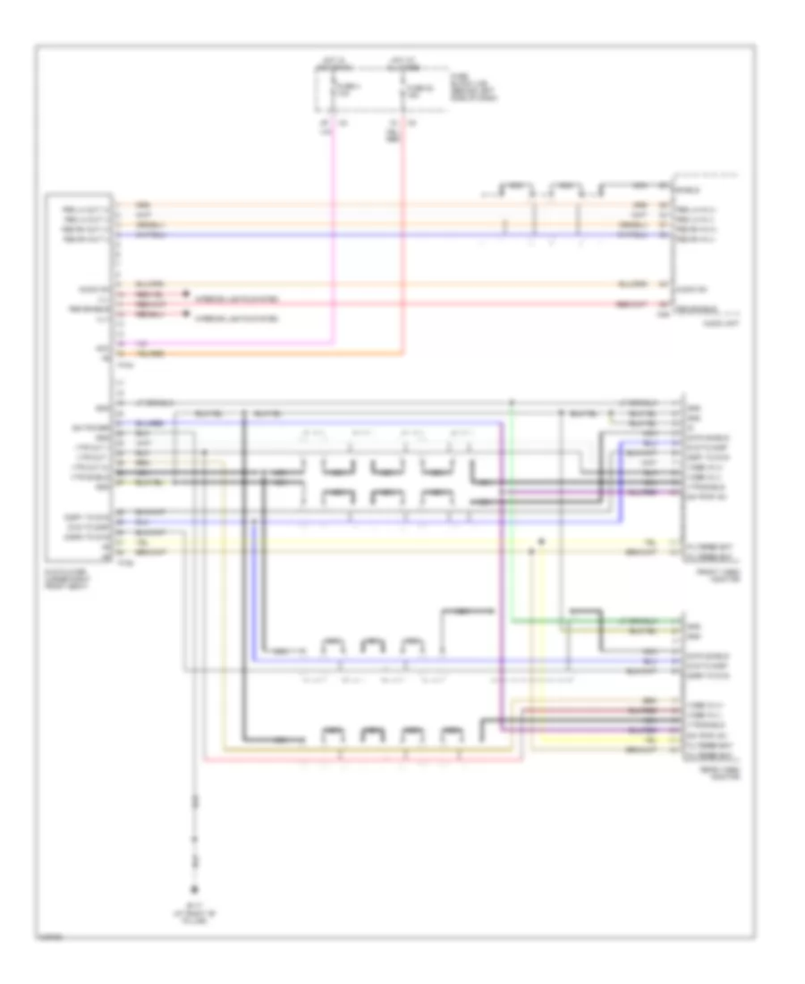
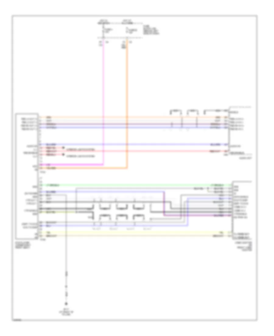
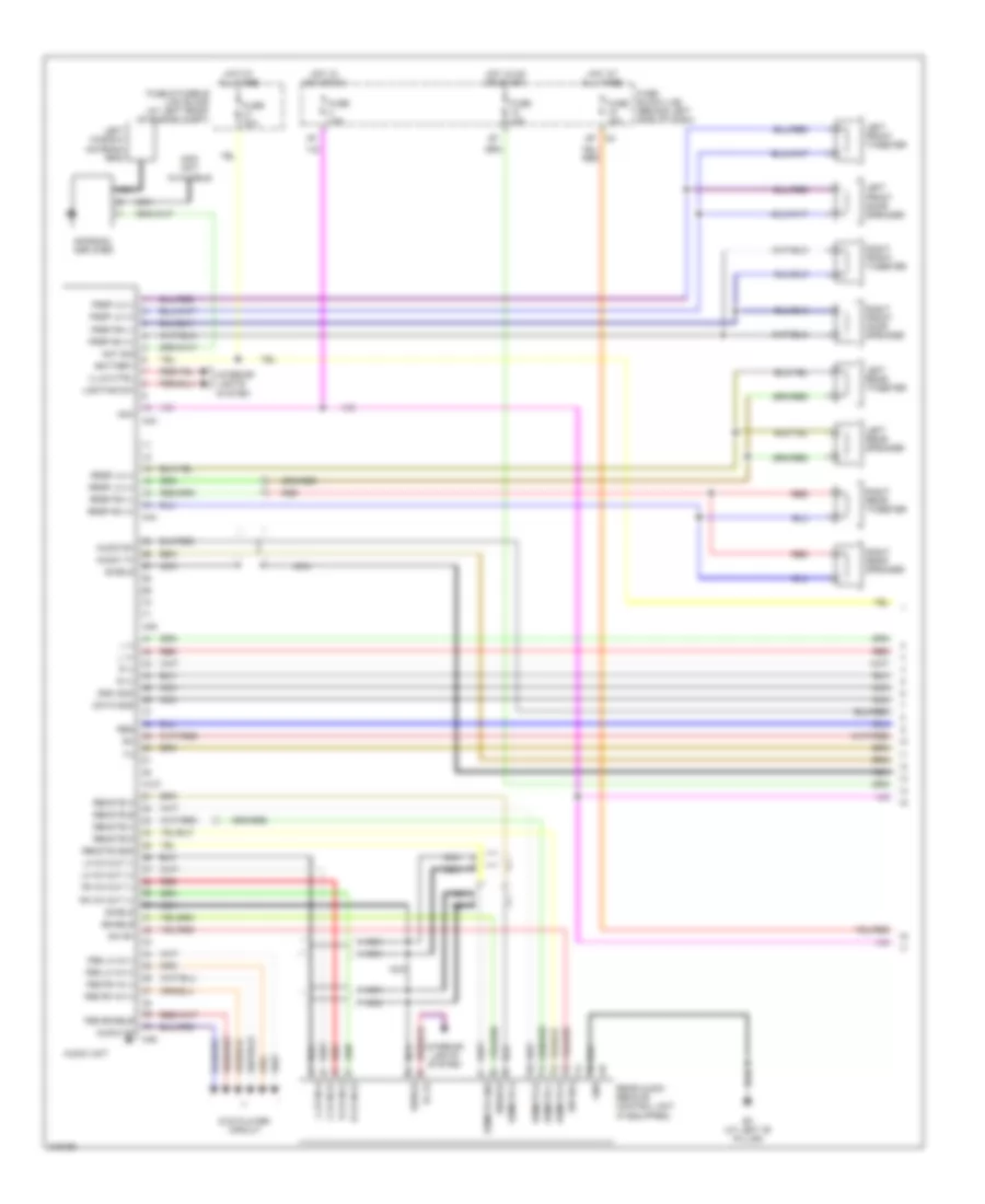
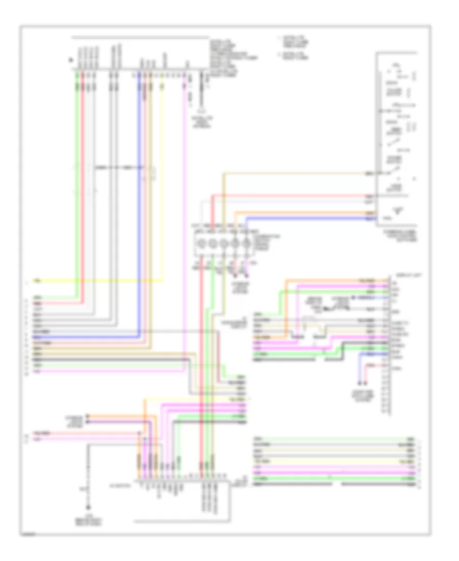
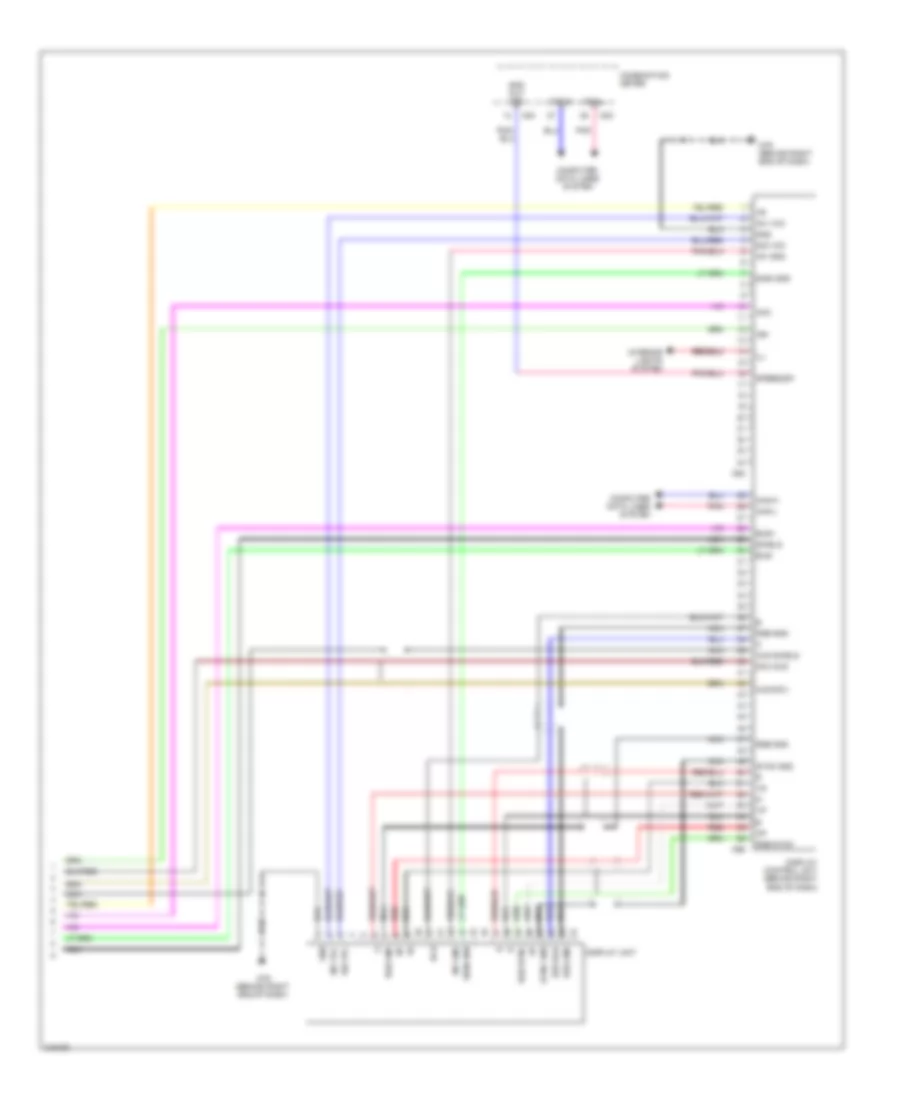
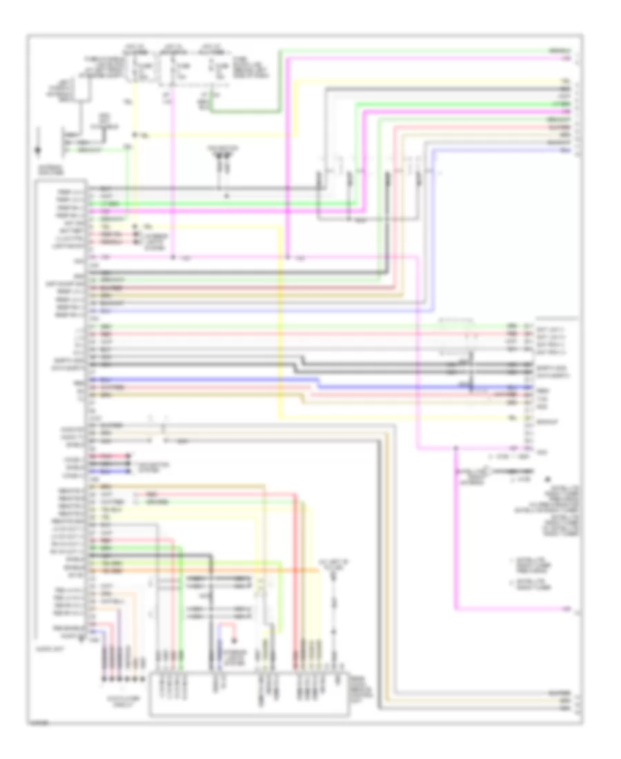
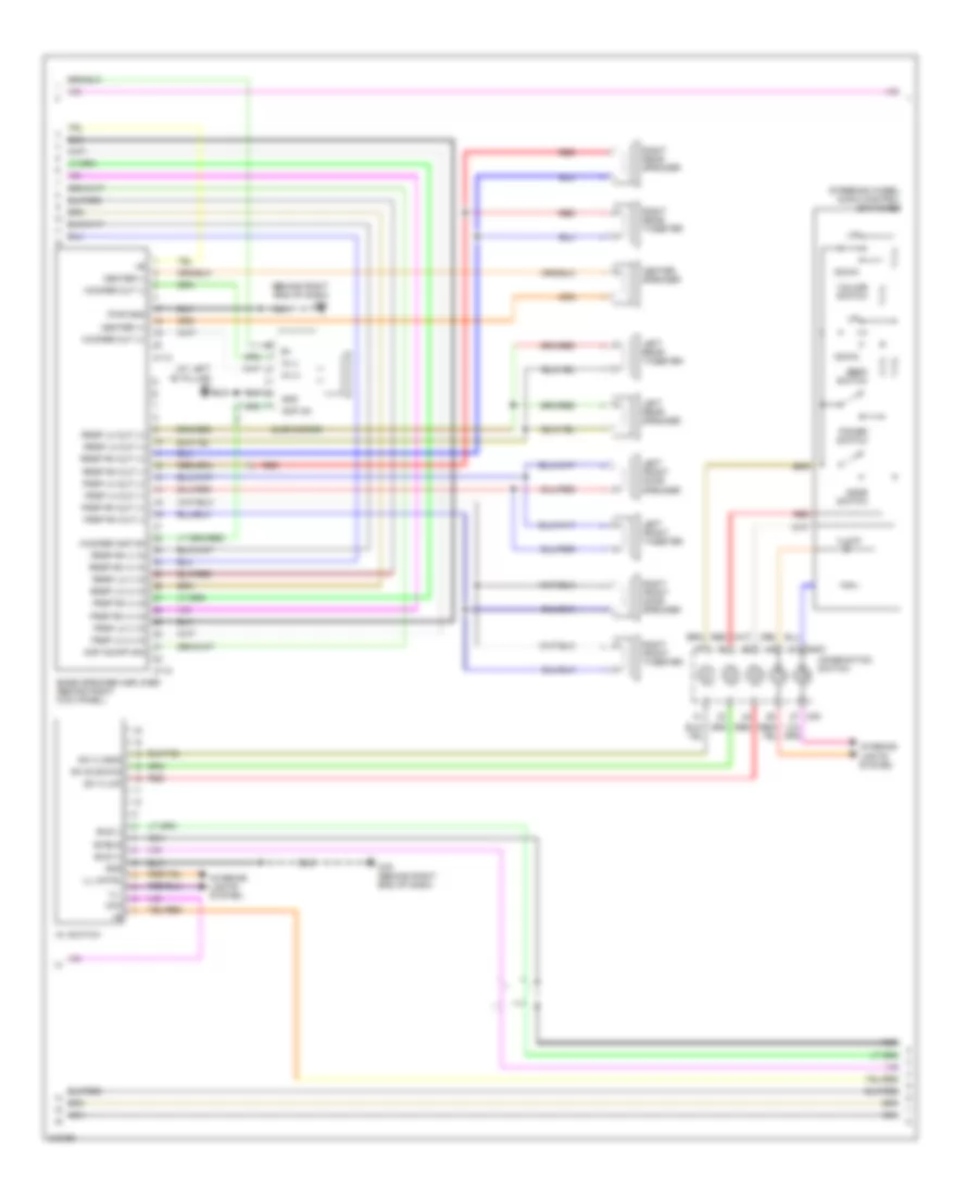
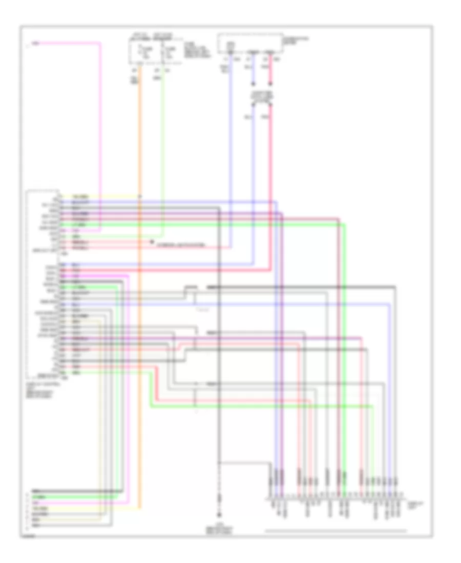
RADIO Base Radio Wiring Diagram (1 of 2) for Nissan Quest S 2006 List of elements for Base Radio Wiring Diagram (1 of 2) for Nissan Quest S 2006: 83 8p m4 Acc Ant sig Antenna amplifier Audio on Audio rx Audio tx Audio unit B7 (at left "b" pillar) Battery Data gnd Dvd player circuit Enable Fes enable Fes lh in (+) Fes lh in (-) Fes rh in (+) Fes rh in (-) Frsp lh (+) Frsp lh (-) Frsp rh (+) Frsp rh (-) Fuse & fusible link block (at left front of engine compt) Fuse 10a Fuse 15a Fuse 20a Fuse block (j/b) (behind left side of dash) Gnd Gnd (sig) Hot at all times Hot in acc or on Hot in on or start Ill (+) Illum ctrl Info not available Interior lights system L (+) L (-) L ch in (+) L ch in (-) Left front door speaker Left front tweeter Left rear speaker Left rear tweeter Left window antenna grid Lh ch out (+) Lh ch out (-) Lighting sw M252 M43 M44 M45 M46 Navigation system Nca Pnk R (+) R (-) R ch in (+) R ch in (-) Rear audio remote control unit (if equipped) Red Remote a Remote b Remote c Remote d Remote gnd Req Rh ch out (+) Rh ch out (-) Right front door speaker Right front tweeter Right rear speaker Right rear tweeter Rrsp lh (+) Rrsp lh (-) Rrsp rh (+) Rrsp rh (-) Shield Sw b(+) Sw b+ Voice (+) Voice (-) Base Radio Wiring Diagram (2 of 2) for Nissan Quest S 2006 List of elements for Base Radio Wiring Diagram (2 of 2) for Nissan Quest S 2006: 47 Acc Audio rx Audio tx Av switch Backup Bus gnd Bus+ Bus- Can-h Can-l Combination switch Computer data lines system Data gnd Dcu-dsp Display unit Down Gnd Gnd (sig) Ign Ill Ill ctrl Illium Interior lights system M102 M30 M79 (behind right end of dash) Mode switch Navigation system Nca Pnk Power switch Red Req1 Rgb sync Rxd Sat lch (+) Sat lch (-) Sat rch (+) Sat rch (-) Satellite radio tuner (pre-wiring) Seek switch Shield Steering wheel audio control switches Sync gnd Txd Volume switch W/ steering wheel audio control switches DVD Player Wiring Diagram, with Dual Monitors for Nissan Quest S 2006 List of elements for DVD Player Wiring Diagram, with Dual Monitors for Nissan Quest S 2006: 45 Acc Audio on Audio unit B117 (at right "b" pillar) Data shield Disp1 to dvd Disp2 to dvd Dsp1 to dvd Dsp2 to dvd Dvd player (under right front seat) Dvd to disp Fes enable Fes lh in (+) Fes lh in (-) Fes lh out (+) Fes lh out (-) Fes rh in (+) Fes rh in (-) Fes rh out (+) Fes rh out (-) Filtered bat Front video monitor Fuse 22 15a Fuse 4 10a Fuse block (j/b) (behind left side of dash) Gnd Hot at all times Hot in acc or on Ill+ Ill- Interior lights system M46 Nca P104 P105 Rear video monitor Shield Sw power Sw pwr +5v Video in (+) Video in (-) Vtr out + Vtr out - Vtr out 2+ Vtr shield DVD Player Wiring Diagram, with Single Monitor for Nissan Quest S 2006 List of elements for DVD Player Wiring Diagram, with Single Monitor for Nissan Quest S 2006: 41 Acc Audio on Audio unit B117 (at right "b" pillar) Data shield Disp1 to dvd Dsp1 to dvd Dvd player (under right front seat) Dvd to disp Fes enable Fes lh in (+) Fes lh in (-) Fes lh out (+) Fes lh out (-) Fes rh in (+) Fes rh in (-) Fes rh out (+) Fes rh out (-) Filtered bat Fuse 22 15a Fuse 4 10a Fuse block (j/b) (behind left side of dash) Gnd Hot at all times Hot in acc or on Ill+ Ill- Interior lights system M46 Nca P104 P105 Shield Sw power Sw pwr +5v Video in (+) Video in (-) Video monitor or front video monitor Vtr out + Vtr out - Vtr shield Mid-Line Radio Wiring Diagram (1 of 3) for Nissan Quest S 2006 List of elements for Mid-Line Radio Wiring Diagram (1 of 3) for Nissan Quest S 2006: 78 8p m4 Acc Ant sig Antenna amplifier Audio on Audio rx Audio tx Audio unit B7 (at left "b" pillar) Battery Data gnd Dvd player circuit Enable Fes enable Fes lh in (+) Fes lh in (-) Fes rh in (+) Fes rh in (-) Frsp lh (+) Frsp lh (-) Frsp rh (+) Frsp rh (-) Fuse & fusible link block (at left front of engine compt) Fuse 10a Fuse 20a Fuse block (j/b) (behind left side of dash) Gnd Gnd (sig) Hot at all times Hot in acc or on Hot in on or start Ill (+) Illum ctrl Info not available Interior lights system L (+) L (-) L ch in (+) L ch in (-) Left front door speaker Left front tweeter Left rear speaker Left rear tweeter Left window antenna grid Lh ch out (+) Lh ch out (-) Lighting sw M127 M43 M44 M45 M46 Nca R (+) R (-) R ch in (+) R ch in (-) Rear audio remote control unit (if equipped) Red Remote a Remote b Remote c Remote d Remote gnd Req Rh ch out (+) Rh ch out (-) Right front door speaker Right front tweeter Right rear speaker Right rear tweeter Rrsp lh (+) Rrsp lh (-) Rrsp rh (+) Rrsp rh (-) Shield Sw b(+) Sw b+ Mid-Line Radio Wiring Diagram (2 of 3) for Nissan Quest S 2006 List of elements for Mid-Line Radio Wiring Diagram (2 of 3) for Nissan Quest S 2006: 55 (behind right of dash) Acc Audio rx Audio tx Av switch Backup Bus+ Bus- Can-h Can-l Combination switch (spiral cable) Computer data lines system Data earth Display unit Down Earth (sig) Gnd Ign Ill Ill ctrl Illum Interior lights system M102 M128 M129 M251 M30 M79 M79 (behind right end of dash) Mode switch Nca Pnk Power switch Radio tuner Radio tuner pre-wiring Red Req1 Rxd Sat lch (+) Sat lch (-) Sat rch (+) Sat rch (-) Satellite Satellite radio antenna Satellite radio tuner pre-wiring (w/ pre-wiring for satellite radio tuner) satellite radio tuner (w/ satellite radio tuner) Seek switch Shield Steering wheel audio control switches Strg sw a (up) Strg sw b (dn) Strg sw c (gnd) Txd Volume switch W/ color display W/ monochrome display Mid-Line Radio Wiring Diagram (3 of 3) for Nissan Quest S 2006 List of elements for Mid-Line Radio Wiring Diagram (3 of 3) for Nissan Quest S 2006: 37 Acc Aud shield Aud-dcu Bus gnd Bus+ Bus- Can-h Can-l Combination meter Computer data lines system Dcu Dcu-aud Display control unit (behind right end of dash) Display unit Dsp-dcu Gnd Ign Ill Interior lights system Inv gnd Inv vcc M23 M24 M79 (behind right end of dash) M94 M95 Nca Pnk Red Rgb gnd Rgb sync Shield Sig vcc Sign gnd Spd out (8p) Speed(8p) Sync gnd Premium Radio Wiring Diagram (1 of 3) for Nissan Quest S 2006 List of elements for Premium Radio Wiring Diagram (1 of 3) for Nissan Quest S 2006: 91 (at left "b" pillar) b7 Acc Amp on/off sig Ant sig Antenna amplifier Audio on Audio rx Audio tx Audio unit Backup Battery Data earth Dvd player circuit Earth (sig) Enable Fes enable Fes lh in (+) Fes lh in (-) Fes rh in (+) Fes rh in (-) Frsp lh (+) Frsp lh (-) Frsp rh (+) Frsp rh (-) Fuse & fusible link block (at left front of engine compt) Fuse 10a Fuse 15a Fuse 20a Fuse block (j/b) (behind left side of dash) Gnd Hot at all times Hot in acc or on Ill (+) Illum ctrl Info not available Interior lights system L (+) L (-) L ch in (+) L ch in (-) Left window antenna grid Lh ch out (+) Lh ch out (-) Lighting sw M127 M128 M129 M251 M43 M44 M45 M46 Navigation system Nca Pnk R (+) R (-) R ch in (+) R ch in (-) Radio tuner Radio tuner pre-wiring Rear audio remote control unit Red Remote a Remote b Remote c Remote d Remote gnd Req Req1 Rh ch out (+) Rh ch out (-) Rrsp lh (+) Rrsp lh (-) Rrsp rh (+) Rrsp rh (-) Rxd Sat lch (+) Sat lch (-) Sat rch (+) Sat rch (-) Satellite Satellite radio antenna Satellite radio tuner (w/ satellite radio tuner) Satellite radio tuner pre-wiring (w/ pre-wiring for satellite radio tuner) Shield Sw b(+) Sw b+ Txd Voice (+) Voice (-) Premium Radio Wiring Diagram (2 of 3) for Nissan Quest S 2006 List of elements for Premium Radio Wiring Diagram (2 of 3) for Nissan Quest S 2006: 66 (at left "b" pillar) b7 (behind right end of dash) m61 Acc Amp on Amp on/off sig Av switch Bose speaker amplifier (behind right kick panel) Bus (+) Bus (-) Center (+) Center (-) Center speaker Combination switch Down Frsp lh (+) in Frsp lh (-) in Frsp lh out (+) Frsp lh out (-) Frsp rh (+) in Frsp rh (-) in Frsp rh out (+) Frsp rh out (-) Gnd Ill Ill cntrl Illium In (+) In (-) Interior lights system Left front door speaker Left front tweeter Left rear speaker Left rear tweeter M102 M112 M113 M30 M79 (behind right end of dash) Mode switch Nca Power switch Pwr gnd Red Right front door speaker Right front tweeter Right rear speaker Right rear tweeter Rrsp lh (+) in Rrsp lh (-) in Rrsp lh out (+) Rrsp lh out (-) Rrsp rh (+) in Rrsp rh (-) in Rrsp rh out (+) Rrsp rh out (-) Seek switch Shield Steering wheel audio control switches Subwoofer Sw a (up) Sw b (down) Sw c (gnd) Volume switch Woofer amp on Woofer out (+) Woofer out (-) Premium Radio Wiring Diagram (3 of 3) for Nissan Quest S 2006 List of elements for Premium Radio Wiring Diagram (3 of 3) for Nissan Quest S 2006: 42 Acc Aud shield Aud-dcu Bus + Bus - Bus gnd Can-h Can-l Combination meter Computer data lines system Dcu-aud Dcu-dsp Display control unit (behind right end of dash) Display unit Dsp-dcu Fuse 10a Fuse 15a Fuse block (j/b) (behind left side of dash) Gnd Hot at all times Hot in on or start Ign Ill Interior lights system Inv gnd Inv vcc M23 M24 M79 (behind right end of dash) M94 M95 Nca Pnk Red Rgb gnd Rgb sync Shield Sig vcc Sign gnd Sign vcc Spd out (8p) Sync gnd
SHIFT INTERLOCK Shift Interlock Wiring Diagram for Nissan Quest S 2006 List of elements for Shift Interlock Wiring Diagram for Nissan Quest S 2006: 15 (at left rear corner of vehicle) back door control unit (at right "c" pillar) right sliding door control unit (behind left rear quarterpanel) left sliding door control unit (behind right end of dash) m61 15p A/t device (behind center of dash) Diode 4 (behind left end of dash) Fuse 1 10a Fuse block (j/b) (behind left side of dash) Hot in on or start Park position switch Prk sw Red Shift lock solenoid Stop lamp switch (behind left side of dash)
STARTING/CHARGING Charging Wiring Diagram for Nissan Quest S 2006 List of elements for Charging Wiring Diagram for Nissan Quest S 2006: 19 Battery Charge indicator Comb- ination meter E112 E116 (at right side of engine compt) F1 generator l Fuse & fusible link box (battery) (left front of engine compt) Fuse 10a Fuse 14 10a Fuse block (j/b) (behind left side of dash) Fusible link a 140a Fusible link box (battery) (left side of engine compt) Hot at all times Hot in on or start M23 M24 Nca Starting circuit Unified meter control unit Starting Wiring Diagram for Nissan Quest S 2006 List of elements for Starting Wiring Diagram for Nissan Quest S 2006: 25 4 speed 5 speed Acc Battery Computer data lines system Cpu E119 E121 E30 E9 (at right rear of engine compartment) Fuse & fusible link box (at left front of engine compt) Fuse 10a Fuse block (j/b) (behind left side of dash) Fusible link k 40a Hot at all times Hot in on or start Ignition switch Intelligent power distribution module engine room (ipdm e/r) (right side of engine compt) Nca Off Park/ neutral position switch (on transaxle) Pnk Start Starter motor (left rear of engine) Starter relay
SUPPLEMENTAL RESTRAINTS Supplemental Restraints Wiring Diagram (1 of 3) for Nissan Quest S 2006 List of elements for Supplemental Restraints Wiring Diagram (1 of 3) for Nissan Quest S 2006: 64 (behind left end of dash) m57 (behind right end of dash) m61 Air bag diagnosis sensor unit (behind right end of dash) Air bag indicator Airbag w/l As1 (+) As1 (-) As2 (+) As2 (-) B113 B71 Clh (+) Clh (-) Combination meter Crh (+) Crh (-) Czs (+) Czs (-) Czs-shld Data link connector (partial) (below lower left side of dash) Dr (-) Dr1 (+) Dr2 (+) Fuse 10a Fuse block (j/b) (behind left end of dash) Gnd Hot in on or start Ign K-line Left front side curtain air bag module (top of left "b" pillar) Left rear side curtain air bag module (near top of left "c" pillar) Left sat (+) Left sat (-) Left side air bag (satellite) sensor (at left "b" pillar) Lh buckle sw Lh curtain 2 (+) Lh curtain 2 (-) M23 M24 M35 Nca Ods in Ods out Plh (+) Plh (-) Prh (+) Prh (-) R-sat (+) R-sat (-) Rh buckle sw Rh curtain 2 (+) Rh curtain 2 (-) Right front seat belt pretensioner (at right "b" pillar) Right front side air bag module (side of right front seat) Right front side curtain air bag module (top of right "b" pillar) Right rear side curtain air bag module (near top of right "c" pillar) Right side air bag (satellite) sensor (at right "b" pillar) Seat belt Seat belt reminder Slh1 (+) Slh1 (-) Srh1 (+) Srh1 (-) Unified meter control unit Supplemental Restraints Wiring Diagram (2 of 3) for Nissan Quest S 2006 List of elements for Supplemental Restraints Wiring Diagram (2 of 3) for Nissan Quest S 2006: 22 (at left "d" pillar) b19 (at left side of engine compartment) e14 (at right "b" pillar) b117 Crash zone sensor (center front of engine compt) Driver air bag module Fastened Front passenger air bag module Left front seat belt pretensioner (at left "b" pillar) Left front side air bag module (side of driver's seat) Left seat belt buckle switch (inside left front seat belt buckle) M101 M103 M105 M106 M77 Nca Red Right seat belt buckle switch (inside right front seat belt buckle) Spiral cable Un- fastened W/ service replacement W/o service replacement Supplemental Restraints Wiring Diagram (3 of 3) for Nissan Quest S 2006 List of elements for Supplemental Restraints Wiring Diagram (3 of 3) for Nissan Quest S 2006: 18 (+) (-) B117 (at right "b" pillar) Belt tension sensor (at base of right "b" pillar) Bts (+) Bts (-) Bts sig Combination meter Gnd Ign M24 M79 (behind right end of dash) Occupant classification system control unit (integral part of front pass seat cushion) Occupant classification system sensor (in right front seat cushion) Ods led Pass air bag off ind Red Sig
TRANSMISSION A/T Wiring Diagram, 4 Speed A/T for Nissan Quest S 2006 List of elements for A/T Wiring Diagram, 4 Speed A/T for Nissan Quest S 2006: 72 (left side of engine compt) dropping resistor (on transaxle) park/neutral position switch A/t check A/t device (od control switch) A/t fluid temp sensor Atcu p & u Automatic transaxle Avcc Can-h Can-l Combination meter Computer data lines system D sw Data link connector (below left side of dash) Duty sol E133 E142 E143 E24 (right side of engine compt) Ect Electric throttle control actuator (at left rear of engine compt) Engine control module (ecm) (right rear of engine compt) Engine coolant temperature sensor (left rear of engine) Exterior lights Fld tmp Fuse 10a Fuse 15a Fuse block (behind left side of dash) Gnd Gnd sens Gnd-a Hot at all times Hot in on or start Ign Intelligent power distribution module engine room (ipdm e/r) (at right side of engine compt) L sw Line press sol valve Lu duty M57 (behind left end of dash) M79 (behind right end of dash) Mem b/u Nca Neutral Od off Over- run clutch sol Ovr/c P/n sw P/t sens Park Pnk R sw Red Revolution sensor (at rear of transaxle) Shift sol valve a Shift sol valve b Sp sens Spd out 2p Ssa Ssb Starting/ charging system Tacho Tcc sol valve Tps 1 Tps 2 Tps gnd Tps pwr Transmission control module (tcm) (behind right side of dash) Turbine revolution sensor (at rear of transaxle) Tv01 Tvoo V sens Vign A/T Wiring Diagram, 5 Speed A/T for Nissan Quest S 2006 List of elements for A/T Wiring Diagram, 5 Speed A/T for Nissan Quest S 2006: 57 (behind center of dash) a/t device (lever switch) (on transaxle) park/neutral position switch A/t fluid temp sensor A/t pv ign relay (behind right end of dash) Automatic transaxle Can-h Can-l Cntrl sol valve a Cntrl sol valve b Cntrl sol valve c Combination meter Computer data lines system E133 E24 (right side of engine compt) Engine control module (right rear of engine compt) F30 F62 Fuse 10a Fuse 15a Fuse block (j/b) (behind left side of dash) Gnd Hot at all times Hot in on or start Ig1 Ig2 Igr5 Intelligent power distribution module (engine room) (right side of engine compt) Nc+ Nc- Nca Otg Pnk Press Range Red Revolution sensor (rear of transaxle) Sens gnd Shift sol valve a Shift sol valve b Shift sol valve c Shift sol valve d Shift sol valve e Sls Slsg Slt Sltg Slu Slug Sol a Sol b Sol c Sol d Sol e Starting/ charging system Transmission control module (tcm) (behind right side of dash) Turbine revolution sensor (rear of transaxle) Vss 1
TRUNK, TAILGATE, FUEL DOOR Automatic Back Door Wiring Diagram for Nissan Quest S 2006 List of elements for Automatic Back Door Wiring Diagram for Nissan Quest S 2006: 82 (at left side of back door) (at right "c" pillar) right sliding door control unit (behind left end of dash) A/t device (behind center of dash) As buzz req Automatic door main switch Automatic sliding door circuit B19 (at left "d" pillar) B42 B66 (at left rear corner of vehicle) B7 (at left "b" pillar) Back door close switch (at left "d" pillar) Back door clutch Back door control unit (at left rear corner of vehicle) Back door encoder Back door handle switch (at center of back door) Back door latch Back door motor Back door warning chime (at left side of back door) Bat (c/b) Bat (f/l) Bat (fuse) Bcm (behind left side of dash) Bus Cinch latch motor Cinch latch mtr Close Close sw Close switch Clutch Clutch ret D403 (at top left rear of roof) Door ajar switch Door lift gate Dr buzz req Flash lamp Fuse & fusible link box (at left front of engine compt) Fuse 12 10a Fuse 17 10a Fuse block (j/b) (behind left side of dash) Fusible link j 50a Gnd Gnd (pwr) Gnd (sig) Half latch switch Half sw Hot at all times Hot in on or start Ign sw Left pinch strip Left sliding door control unit (behind left rear quarterpanel) Lh pinch strip M18 M19 M20 M57 M57 (behind left end of dash) M61 (behind right end of dash) Nca Open Open sw Open switch Open/close sw Outside handle P/wdw P/wdw rap Park sw Park switch Pbd Pbd close sw Pinch strip gnd Pnk Power tops system Power windows system Psd main sw Pwr Rh pinch strip Right pinch strip (at right side of back door) Sig-a Sig-b Speaker (+) Speaker (-) Fuel Door Release Wiring Diagram for Nissan Quest S 2006 List of elements for Fuel Door Release Wiring Diagram for Nissan Quest S 2006: 8 B7 (at left "b" pillar) Fuel lid opener actuator (behind left rear quarterpanel) Fuel lid opener relay (behind left side of dash) Fuel lid opener switch Fuse 15a Fuse block (j/b) (behind left side of dash) Hot at all times M57 (behind left end of dash) Right & Left Sliding Door Wiring Diagram (1 of 2) for Nissan Quest S 2006 List of elements for Right & Left Sliding Door Wiring Diagram (1 of 2) for Nissan Quest S 2006: 83 (behind center of dash) a/t device 16p As psd Automatic back door circuit Automatic door main switch B117 (at right "b" pillar) B143 B144 B401 Bat (c/b) Bat (f/l) Bat (fuse) Bcm (behind left side of dash) Bus Buzzer req Child lockout sw Child lockout switch Circuit breaker 1 (at right kick panel) - Clm (+) Clm (-) Close Clutch Clutch ret Door lock all Door sw (rl) Door sw (rr) Door unlock all Dr psd Full latch switch Fuse & fusible link box (at left front of engine compartment) Fuse 10a Fuse block (j/b) (behind left side of dash) Fusible link i 40a Fusible link j 50a Gnd Gnd (pwr) Gnd (sig) Half latch sw Half switch Handle switch Hot at all times Hot in on or start Ign sw Lock Lock motor Lock mtr (-) Lock sw Lock switch M18 M19 M20 M57 (behind left end of dash) M61 (behind right end of dash) Main sw Neutral switch Open Open/close sw P/wdw P/wdw rap Park sw Park switch Psd disable sw Pwr Red Right cinch latch motor (at rear of sliding door) Right cinch latch switch (at rear of sliding door) Right latch release actuator (at front of sliding door) Right sliding door clutch Right sliding door contact switch (door) (in center of sliding door) Right sliding door contact switch (pillar) (at right "b" pillar) Right sliding door control unit (at right "c" pillar) Right sliding door encoder (behind right quarterpanel) Right sliding door latch control unit (at center of sliding door) Right sliding door lock actuator (at front of sliding door) Right sliding door motor Right sliding door motor assembly Right sliding door open/close switch (at right "b" pillar) Right sliding door remote control switch Right sliding door switch (right "c" pillar) S/door sw Sig-a Sig-b Unlock Right & Left Sliding Door Wiring Diagram (2 of 2) for Nissan Quest S 2006 List of elements for Right & Left Sliding Door Wiring Diagram (2 of 2) for Nissan Quest S 2006: 67 (at left "b" pillar) Automatic back door circuit B42 B501 B60 B61 B67 (behind left rear quarterpanel) B7 (at left "b" pillar) Back door control unit (at left rear rear corner of vehicle) Bat (c/b) Bat (fuse) Buzzer req Child lockout sw Child lockout switch Circuit breaker 2 (at left kick panel) Clm (+) Clm (-) Close Clutch Clutch ret Door unlock all Fuel door interlock switch (behind left rear quarter- panel) Fuel dr sw Full latch switch Fuse & fusible link box (at left front of engine compartment) Fuse 10a Fuse block (j/b) (behind left side of dash) Fusible link m 40a Gnd Half latch sw Half switch Handle switch Hot at all times Hot in on or start Ign sw Left cinch latch motor (at rear of sliding door) Left cinch latch switch (at rear of sliding door) Left latch release actuator (at front of sliding door) Left sliding door clutch Left sliding door contact switch (door) (in center of sliding door) Left sliding door contact switch (pillar) (near top of left "b" pillar) Left sliding door control unit (behind left rear quarterpanel) Left sliding door encoder (behind left rear quarterpanel) Left sliding door latch control unit (at center of sliding door) Left sliding door lock actuator (at front of sliding door) Left sliding door motor Left sliding door motor assembly Left sliding door open/close switch (at left "b" pillar) Left sliding door remote control switch Left sliding door switch (at left "c" pillar) Lock Lock motor Lock mtr (-) Lock sw Lock switch Neutral switch Open Open/close sw P/wdw Park sw Psd disable sw Pwr Red S/door sw Sig-a Sig-b Unlock Right Sliding Door Wiring Diagram for Nissan Quest S 2006 List of elements for Right Sliding Door Wiring Diagram for Nissan Quest S 2006: 80 (behind center of dash) a/t device 16p As psd Automatic back door circuit Automatic door main switch B117 (at right "b" pillar) B143 B144 B401 Bat (c/b) Bat (f/l) Bat (fuse) Bcm (behind left side of dash) Bus Buzzer req Child lockout sw Child lockout switch Circuit breaker 1 (at right kick panel) Clm (+) Clm (-) Close Clutch Clutch ret Door lock all Door sw (rr) Door unlock all Full latch switch Fuse & fusible link box (at left front of engine compt) Fuse 10a Fuse block (j/b) (behind left side of dash) Fusible link i 40a Fusible link j 50a Gnd Gnd (pwr) Gnd (sig) Half latch sw Half switch Handle switch Hot at all times Hot in on or start Ign sw Lock Lock motor Lock mtr (-) Lock sw Lock switch M18 M19 M57 (behind left end of dash) M61 (behind right end of dash) Main sw Neutral switch Open Open/close sw P/wdw P/wdw rap Park sw Park switch Psd disable sw Pwr Red Right cinch latch motor (at rear of sliding door) Right cinch latch switch (at rear of sliding door) Right latch release actuator (at front of sliding door) Right sliding door clutch Right sliding door contact switch (door) (in center of sliding door) Right sliding door contact switch (pillar) (at right "b" pillar) Right sliding door control unit (at right "c" pillar) Right sliding door encoder (behind right quarterpanel) Right sliding door latch control unit (at center of sliding door) Right sliding door lock actuator (at front of sliding door) Right sliding door motor Right sliding door motor assembly Right sliding door open/close switch (at right "b" pillar) Right sliding door remote control switch Right sliding door switch (at right "c'' pillar) S/door sw Sig-a Sig-b Unlock
WARNING SYSTEMS Warning Systems Wiring Diagram for Nissan Quest S 2006 List of elements for Warning Systems Wiring Diagram for Nissan Quest S 2006: 62 Air bag diagnosis sensor unit (behind right end of dash) B7 (at left "b" pillar) Bat (f/l) Body control module (bcm) (behind left side of dash) Buckle sw Buzzer Can-h Can-l Combi sw input 1 Combi sw input 2 Combi sw input 3 Combi sw input 4 Combi sw input 5 Combi sw output 1 Combi sw output 2 Combi sw output 3 Combi sw output 4 Combi sw output 5 Combination meter Combination switch Computer data lines system Door ind Door sw (dr) E30 Fuse & fusible link block (at left front of engine compartment) Fuse 10a Fuse 15a Fuse block (j/b) (behind left side of dash) Fusible link j 50a Gnd Hot at all times Hot in on or start Ign sw Input 1 Input 2 Input 3 Input 4 Input 5 Key sw Key switch Left front door switch (at left "b" pillar) Left seat belt buckle switch (in driver side seat belt buckle assembly) M18 M19 M20 M23 M24 M35 M61 (behind right end of dash) Output 1 Output 2 Output 3 Output 4 Output 5 P/ warn check Pnk Red Seat belt Seat belt ind Tire pressure ind Tire pressure warning check connector (behind lower center of dash) Unified meter control unit
WIPER/WASHER Front Wiper/Washer Wiring Diagram for Nissan Quest S 2006 List of elements for Front Wiper/Washer Wiring Diagram for Nissan Quest S 2006: 55 Bat Body control module (bcm) (behind left side of dash) Can-h Can-l Combination meter Combination switch Computer data lines system Cpu E121 E122 E124 E15 (at left side of engine compt) E24 (at right side of engine compt) E30 Front and rear washer motor (at right front of engine compt) Front wiper hi relay Front wiper motor (at left rear of engine compt) Front wiper relay Fuse & fusible link block (at left front of engine compt) Fuse 10a Fuse 15a Fuse 30a Fuse block (j/b) (behind left side of dash) Fusible link j 50a Gnd High Hot at all times Hot in on or start Ign Ignition relay Input 1 Input 2 Input 3 Input 4 Input 5 Ipdm e/r (at right side of engine compt) Low M18 M19 M23 M28 M61 (behind right end of dash) Move Output 1 Output 2 Output 3 Output 4 Output 5 Pnk Red Stop Unified meter control unit Wash mtr Washer fluid level switch (at right front of engine compt) Washer ind Rear Washer/Wiper Wiring Diagram for Nissan Quest S 2006 List of elements for Rear Washer/Wiper Wiring Diagram for Nissan Quest S 2006: 47 Auto stop Bat Body control module (bcm) (behind left side of dash) Case earth Combination meter Combination switch D403 (at top left rear of roof) E124 E15 (at left side of engine compt) E30 Front and rear washer motor (at right front of engine compt) Fuse & fusible link box (at left front of engine compt) Fuse 10a Fuse block (j/b) (behind left side of dash) Fusible link j 50a Gnd High Hot at all times Hot in on or start Ign Input 1 Input 2 Input 3 Input 4 Input 5 Ipdm e/r (at right side of engine compt) Low M18 M19 M20 M23 M28 M61 (behind right end of dash) Move Mtr output Output 1 Output 2 Output 3 Output 4 Output 5 Rear wiper motor (at center of back door) Red Stop Unified meter control unit Wash mtr Washer fluid level switch (at right front of engine compt) Washer ind