Diagram sections — 31 (74 total)
AIR CONDITIONING ANTI-LOCK BRAKES ANTI-THEFT BODY CONTROL MODULES COMPUTER DATA LINES COOLING FAN CRUISE CONTROL DEFOGGERS ELECTRONIC POWER STEERING ENGINE PERFORMANCE EXTERIOR LIGHTS GROUND DISTRIBUTION HEADLIGHTS HORN INSTRUMENT CLUSTER INTERIOR LIGHTS NAVIGATION POWER DISTRIBUTION POWER DOOR LOCKS POWER MIRRORS POWER SEATS POWER TOP/SUNROOF POWER WINDOWS RADIO SHIFT INTERLOCK STARTING/CHARGING SUPPLEMENTAL RESTRAINTS TRANSMISSION TRUNK, TAILGATE, FUEL DOOR WARNING SYSTEMS WIPER/WASHER
AIR CONDITIONING Automatic A/C Wiring Diagram (1 of 2) for Nissan Rogue Krom 2011 List of elements for Automatic A/C Wiring Diagram (1 of 2) for Nissan Rogue Krom 2011: 69 (behind left side of dash) Acc Air mix door motor (right side of hvac unit) Aircon sw Amb sens Ambient sensor Amp Auto amplifier Bat Bcm (body control module) (behind left end of dash) Blower fan sw Blower motor (left side of hvac unit) Blower relay Can-h Can-l Combination meter Comp on Computer data lines system Con recognition sig Defogger system E105 Engine coolant temp sig Fan control amplifier (left side of hvac unit) Fan on Fr/fan f/b Fr/fan out Fr/ign 2 Fuse 10a Fuse 15a Fuse block (j/b) (behind left end of dash) Fusible link d 100a Fusible link holder Gnd (pwr) Hot at all times Hot in on or start Ign Ignition switch In-vehicle sensor Incar sens Int sens Intake door motor (behind right side of dash) Intake sensor (on condenser) Interior lights systems Lan (+) Lan (-) Light (+) Light (-) M301 M301 m99 M34 M54 M55 M65 M76 M76 (behind left side of dash) M77 M99 Mode door motor (left side of hvac unit) Off Outside temp pwr Pnk Red Rr/def f/b Rr/def sw Sens gnd Start Sun sens Sunload sensor Water temp Automatic A/C Wiring Diagram (2 of 2) for Nissan Rogue Krom 2011 List of elements for Automatic A/C Wiring Diagram (2 of 2) for Nissan Rogue Krom 2011: 52 (left front of engine compt) (on ipdm e/r (intelligent power distribution module engine room)) (right front of engine compt) A/c compressor (lower left front of eng) A/c relay Avcc 2 California Computer data lines system Cooling fan motor 1 (left front of engine compt) Cooling fan motor 2 (right front of engine compt) Cooling fan relay 1 Cooling fan relay 2 Cooling fan relay 3 Cooling fan relay 4 Cooling fan relay 5 Cpu E10 E105 E11 E13 E14 E15 E16 E21 E38 E38 (right front of engine compt) Ecm (left side of engine compt) Engine coolant temperature sensor (rear of engine) Except california F121 F123 e6 F6 (left front of engine) Fuse 10a Fuse 15a Fuse 20a Fuse, fusible link & relay box (left side of engine compt) Fusible link m 40a Gnd a Gnda-tw Hot at all times Hot in on or start Ignition relay Ipdm e/r (intelligent power distribution module engine room) (left side of engine compt) M77 Pdpress Pnk Refrigerant pressure sensor (left front of engine compt) Scvpos Tumble control valve actuator (right rear of engine) Tumble control valve position sensor Vehcan-h Vehcan-l Manual A/C Wiring Diagram (1 of 2) for Nissan Rogue Krom 2011 List of elements for Manual A/C Wiring Diagram (1 of 2) for Nissan Rogue Krom 2011: 66 (left front of engine compt) A/c amplifier (behind center of dash) A/c sw sig Air mix door motor (right side of hvac unit) Aircon sw Avcc2 Bat Bcm (body control module) (behind left end of dash) Blower motor (left side of hvac unit) Blower relay Blower sig Blwr fan sw California Can-h Can-l Com (lan sig) Defogger system E105 m77 E16 E21 Ecm (left side of engine compt) Engine coolant temperature sensor (rear of engine) Except california F123 Fan control amplifier (left side of hvac unit) Fan control sig Fan on Fuse 10a Fuse 15a Fuse block (j/b) (behind left end of dash) Fusible link d 100a Fusible link holder Gnd Gnd-a Gnda-tw Hot at all times Hot in on Hot in on or start Ign Ign2 Int sens Intake door motor (behind right side of dash) Intake sensor (on condenser) Interior Lights system Lt+ Lt- M301 M65 M76 (behind left side of dash) M99 M99 m301 Mode door motor (left side of hvac unit) Pdpress Pnk Pwr sply Red Refrigerant pressure sensor (left front of engine compt) Rr def f/s Rr def sw Scvpos Sens gnd Tumble control valve actuator (right rear of engine) Tumble control valve position sensor Vehcan-h Vehcan-l Manual A/C Wiring Diagram (2 of 2) for Nissan Rogue Krom 2011 List of elements for Manual A/C Wiring Diagram (2 of 2) for Nissan Rogue Krom 2011: 30 (on ipdm e/r (intelligent power distribution module engine room)) A/c compressor (lower left front of engine) A/c relay Computer data lines system Cooling fan motor 1 (left front of engine compt) Cooling fan motor 2 (right front of engine compt) Cooling fan relay 1 Cooling fan relay 2 Cooling fan relay 3 Cooling fan relay 4 Cooling fan relay 5 Cpu E10 E11 E13 E14 E15 E38 (right front of engine compt) F121 F6 (left front of engine) Fuse 10a Fuse 15a Fuse 20a Fuse, fusible link & relay box (left side of engine compt) Fusible link m 40a Hot at all times Hot in on or start Ignition relay Ipdm e/r (intelligent power distribution module engine room) (left side of engine compt) Pnk
ANTI-LOCK BRAKES Anti-lock Brakes Wiring Diagram, with VDC for Nissan Rogue Krom 2011 List of elements for Anti-lock Brakes Wiring Diagram, with VDC for Nissan Rogue Krom 2011: 70 (right rear of engine compt) 4wd comm Abs actuator & electric unit (control unit) Abs, slip, vdc off & brake ind Actr Ascd brake switch (on brake pedal bracket) Ascd cancel sw B11 B26 (in left "d" pillar) Brake fluid level switch Brake fluid sw Can h Can l Can-h Can-l Combination meter Computer data lines system Diag k E101 E105 E15 E21 (left front of engine compt) E35 (right rear of engine compt) Fl sens sig Fl sens vb Fr sens sig Fr sens vb Fuse 10a Fuse block (j/b) (behind left end of dash) Fuse, fusible link & relay box (left side of engine compt) Fusible link h 30a Fusible link i 50a G check G gnd G sw2 Gnd Gnd a Gnd m Gsw1 Hot at all times Hot in on or start Ign Interior lights system Ipdm e/r (intelligent power distribution module engine room) (left side of engine compt) Left front wheel sensor Left rear wheel sensor M35 (behind right side of dash) M77 Motor Parking brake sw Parking brake switch Pnk Red Right front wheel sensor Right rear wheel sensor Rl sens sig Rl sens vb Rr sens sig Rr sens vb Serial + Serial - Shield Steering angle sensor (on steering column) Stop lamp sw Stoplight switch (on brake pedal bracket) Transmissions system Vcc (power) Vdc off sw Vdc off switch Yaw rate/side/ decel g sensor Anti-lock Brakes Wiring Diagram, without VDC for Nissan Rogue Krom 2011 List of elements for Anti-lock Brakes Wiring Diagram, without VDC for Nissan Rogue Krom 2011: 60 (right rear of engine compt) Abs & brake ind Abs actuator & electric unit (control unit) Actr B11 Brake fluid level switch Brake fluid sw Can h Can l Can-h Can-l Combination meter Computer data lines system Diag k E101 E105 E105 m77 E15 E21 (left front of engine compt) E35 (right rear of engine compt) Fl sens sig Fl sens vb Fr sens sig Fr sens vb Fuse 10a Fuse block (j/b) (behind left end of dash) Fuse, fusible link & relay box (left side of engine compt) Fusible link h 30a Fusible link i 50a G check G gnd G sensor (awd) (in center console) G sw2 Gnd Gnd a Gnd m Gs1 Gs2 Gst Gsw1 Hot at all times Hot in on or start Ign Ipdm e/r (intelligent power distribution module engine room) (left side of engine compt) Left front wheel sensor Left rear wheel sensor M77 Motor Parking brake sw Parking brake switch Pnk Red Right front wheel sensor Right rear wheel sensor Rl sens sig Rl sens vb Rr sens sig Rr sens vb Stop lamp sw Stoplight switch (on brake pedal bracket)
ANTI-THEFT Forced Entry Wiring Diagram for Nissan Rogue Krom 2011 List of elements for Forced Entry Wiring Diagram for Nissan Rogue Krom 2011: 76 +batt +ign B26 (in left "d" pillar) B77 B79 Back door lock assembly (bottom center of back door) Back door sw Back door switch Bat fl Between full stroke & n Body control module (bcm) (behind left end of dash) Can-h Can-l Cdl lock sw Cdl unlock sw Combination meter Computer data lines system Cpu D152 D153 D157 D159 D182 D183 D41 Door lock & unlock switch Dr sw as Dr sw dr Dr sw rl Dr sw rr Driver side front door lock assembly (rear of driver's door) Driver side front door switch (left "b" pillar) E105 E11 E13 E15 E38 (right front of engine compt) Full stroke Fuse & fusible link & relay box (left side of engine compt) Fuse 10a Fuse 15a Fuse 20a Fuse block (j/b) (behind left end of dash) Fusible link j 50a Gnd Gnd (power) Horn rly Horns system Hot at all times Hot in on or start Ign sw Ignition relay Ipdm e/r (intelligent power distribution module engine room) (left side of engine compt) Key cyl lock sw Key cyl unlock sw Left rear door switch (left "c" pillar) M11 M13 M18 M35 (behind right side of dash) M65 M66 M67 M76 (behind left side of dash) M77 M81 Passenger side front door switch (right "b" pillar) Passenger side front power window switch Pnk Power window main switch Red Right rear door switch (right "c" pillar) Security ind Security ind out Switch Unlock lock switch Immobilizer Wiring Diagram for Nissan Rogue Krom 2011 List of elements for Immobilizer Wiring Diagram for Nissan Rogue Krom 2011: 32 Bat fl Bcm (body control module) (behind left end of dash) Can-h Can-l Clk Combination meter Computer data lines system Data E105 E15 E16 Ecm (left side of engine compt) Fuse & fusible link & relay box (left side of engine compt) Fuse 10a Fuse 20a Fuse block (j/b) (behind left end of dash) Fusible link j 50a Gnd Hot at all times Hot in on or start Ign Immob ant Ipdm e/r (intelligent power distribution module engine room) (left side of engine compt) M35 (behind right side of dash) M65 M67 M77 Nats antenna amplifier (behind left side of dash) Pnk Red Security Security ind
BODY CONTROL MODULES Body Control Modules Wiring Diagram for Nissan Rogue Krom 2011 List of elements for Body Control Modules Wiring Diagram for Nissan Rogue Krom 2011: 83 Acc Air conditioning & defogger systems Air conditioning system Aircon sw Anti-theft system Auto light sens in Back door open sw Back door opener out Back door sw Bat (fuse) Bat fl Bat saver Bcm (body control module) (behind left end of dash) Blower fan sw Brake sw Can-h Can-l Cdl lock sw Cdl unlock sw Comb sw in 1 Comb sw in 2 Comb sw in 3 Comb sw in 4 Comb sw in 5 Comb sw out 1 Comb sw out 2 Comb sw out 3 Comb sw out 4 Comb sw out 5 Computer data lines system Door locks system Door sw rl Dr sw as Dr sw dr Dr sw rr E105 Exterior lights system Flasher out (left) Flasher out (right) Fuse 10a Fuse block (j/b) (behind left end of dash) Fuse, fusible link & relay box (left side of engine compt) Fusible link j 50a Gnd Hazard sw Headlights system Hot at all times Hot in acc or on Hot in on or start Ign sw Immob ant (clock) Immob ant (rx, tx) Interior lights system Key cyl lock sw Key cyl unlock sw Key ring out Key sw Keyless tuner pwr Keyless tuner sens gnd Keyless tuner sig Lock out all Luggage lamp out M35 (behind right side of dash) M65 M66 M67 M77 Pnk Power tops & power windows systems Pwr wdw out bat Pwr wdw out rap Red Room lamp out Rr def sw Rr wip auto stop Rr wip mtr out Security ind out Sens pwr sply Trunk, tailgate, fuel doors system Unlck out other Unlock out (dr) Warning systems Wiper/washer system
COMPUTER DATA LINES Computer Data Lines Wiring Diagram for Nissan Rogue Krom 2011 List of elements for Computer Data Lines Wiring Diagram for Nissan Rogue Krom 2011: 39 (behind left side of dash) m76 Abs actuator & electric unit (control unit) (right rear of engine compt) Air bag diagnosis sensor unit (w/ advanced air bag) (under center console) Awd control unit (w/ awd & w/o vdc) (behind left end of dash) Bcm (body control module) (behind left end of dash) Can h Can l Can-h Can-l Combination meter Cpu Data link connector (under left side of dash) Diag k E105 E13 E16 Ecm (left side of engine compt) Eps control unit (behind left side of dash) F123 Fuse 1 10a Fuse 8 10a Fuse block (j/b) (behind left end of dash) Hot at all times Hot in on or start Intelligent key unit (if equipped) (behind left end of dash) Ipdm e/r (intelligent power distribution module engine room) (left side of engine compt) M37 M59 M60 M65 M77 Nca Pnk Steering angle sensor (w/ vdc) (on steering column) Tcm (transmission control module) (left rear of engine compt) Unified meter control unit Veh can-h Veh can-l Veh k-line
COOLING FAN Cooling Fan Wiring Diagram for Nissan Rogue Krom 2011 List of elements for Cooling Fan Wiring Diagram for Nissan Rogue Krom 2011: 36 (on ipdm e/r (intelligent power distribution module engine room)) California Computer data lines system Cooling fan motor 1 (left front of engine compt) Cooling fan motor 2 (right front of engine compt) Cooling fan relay 1 Cooling fan relay 2 Cooling fan relay 3 Cooling fan relay 4 Cooling fan relay 5 Cpu E10 E11 E13 E14 E15 E16 E21 (left front of engine compt) E38 (right front of engine compt) Ecm (left side of engine compt) Engine coolant temperature sensor (rear of engine) Except california Fuse & fusible link block Fuse 15a Fuse 20a Fusible link m 40a Gnda-tw Hot at all times Hot in on or start Ignition relay Ipdm e/r (intelligent power distribution module engine room) (left side of engine compt) Pnk Tumble control valve actuator Tumble control valve position sensor Vehcan-h Vehcan-l
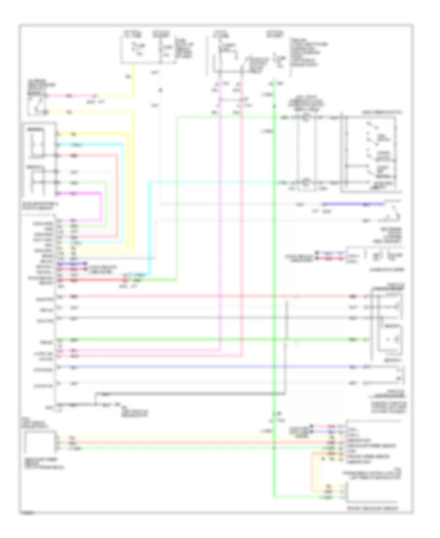
CRUISE CONTROL Cruise Control Wiring Diagram for Nissan Rogue Krom 2011 List of elements for Cruise Control Wiring Diagram for Nissan Rogue Krom 2011: 72 (m33: top of steering column) combination switch (spiral cable) (on brake pedal bracket) stoplight switch Accel/res switch Accelerator pedal position sensor Acsd steering switch Aps1 Aps2 Ascd brake switch (on brake pedal bracket) Ascdsw Avcc-tps Avcc1-aps1 Avcc2-aps2 Bncsw Brake Can-h Can-l Cancel Coast/ set Combination meter Computer data lines system Cruise ind E105 E13 E15 E16 E21 (left front of engine compt) Ecm (left side of engine compt) Electric throttle control actuator (on throttle body) F121 F123 Fuse 10a Fuse 61 15a Fuse block j/b (behind left end of dash) Gnd Gnda-aps1 Gnda-aps2 Gnda-ascdsw Gnda-tps Hot at all all times Hot at all times Hot in on or start Ipdm e/r (intelligent power distribution module engine room) (left side of engine compt) M33 M352 M77 M77 e105 Main switch Motor1-b1 Motor2-b1 Motrly-b1 Nca Pnk Primary secondary sensor Primary speed sensor Red Secondary speed sensor Secondary speed sensor (top of transmission) Sensor 1 Sensor 2 Sensor gnd Set ind Switch Tcm (transmission control module) (left rear of engine compt) Throttle control motor Throttle control motor relay Throttle position sensor Tps1-b1 Tps2-b1 Vehcan-h Vehcan-l Vign Vmot-b1
DEFOGGERS Defoggers Wiring Diagram for Nissan Rogue Krom 2011 List of elements for Defoggers Wiring Diagram for Nissan Rogue Krom 2011: 56 +ig A/c amplifier (rear window defogger switch) (behind center of dash) Auto amplifier (rear window defogger switch) Automatic a/c B159 B26 (in left "d" pillar) B79 Bat fl Bat fuse Bcm (body control module) (behind left end of dash) Can-h Can-l Computer data lines system Cpu D152 D159 D160 D182 D41 Door mirror defogger relay (w/ door mirror defogger) (on fuse block (j/b)) Driver side door mirror E101 b11 E105 E11 E13 E38 (right front of engine compt) Fuse & fusible link block Fuse 10a Fuse 15a Fuse 20a Fuse block (j/b) (behind left end of dash) Fusible link j 50a Gnd Gnd (pwr) Hot at all times Hot in on or start Ignition relay Ipdm e/r (intelligent power distribution module engine room) (left side of engine compt) M19 M35 (behind right side of dash) M54 M55 M65 M67 M76 (behind left side of dash) M77 M81 Manual a/c Passenger side door mirror Pnk Rear def sw Rear window defogger (w/ door mirror defogger) d185 Rear window defogger relay Rr def Rr def f/s Rr def sw
ELECTRONIC POWER STEERING Electronic Power Steering Wiring Diagram for Nissan Rogue Krom 2011 List of elements for Electronic Power Steering Wiring Diagram for Nissan Rogue Krom 2011: 22 (behind left side of dash) m43 Bat Can-h Can-l Combination meter Computer data lines system E106 Eps Eps control unit (behind left side of dash) Fuse 10a Fuse block (j/b) (behind left end of dash) Fuse, fusible link & relay box (left side of engine compt) Fusible link f 60a Gnd Hot at all times Hot in on or start Ign M37 M38 N78 Pnk Red
ENGINE PERFORMANCE
2.5L 2.5L, Engine Performance Wiring Diagram (1 of 4) for Nissan Rogue Krom 2011 List of elements for 2.5L, Engine Performance Wiring Diagram (1 of 4) for Nissan Rogue Krom 2011: 52 (top of engine) fuel injectors A/f+1 A/f-1 A/fh1 Avcc1-tps-b1 E21 (left front of engine compt) E7 f121 Engine control module (ecm) (left side of engine compt) Engine coolant temperature sensor (rear of engine) Evap Evap canister purge volume control solenoid valve (right front of engine) F121 F123 Fpr Gnd Gnda-o2sr1,2,3 Gnda-pdpres Gnda-tps-b1 Gnda-tw Ign 1 Ign 2 Ign 3 Ign 4 Inj 1 Inj 2 Inj 3 Inj 4 Motor1-b1 Motor2-b1 Motrly-b1 Nca O2hr1 O2hr2,3rdo2h O2sr1 O2sr2 Pdpres Pnk Qa-gnda-ta1 Red Refrigerant pressure sensor (left front of engine compt) Scv1 Scv2 Scvpos Ssoff Ta1 Tps1-b1 Tps2-b1 Tumble control valve actuator (california) (right rear of engine) Tumble control valve motor Tumble control valve position sensor Vmot-b1 Vscv 2.5L, Engine Performance Wiring Diagram (2 of 4) for Nissan Rogue Krom 2011 List of elements for 2.5L, Engine Performance Wiring Diagram (2 of 4) for Nissan Rogue Krom 2011: 35 (top of engine) Condenser (top of engine) E105 E13 E14 E15 E21 (left front of engine compt) Ecm relay Electric throttle control actuator (on throttle body) F121 F122 F123 F127 F9 (left front of engine) Fuel pump relay Fuse 15a Fuse 20a Hot at all times Hot in on or start Ignition coil 1 (w/ power transistor) (california) Ignition coil 2 (w/ power transistor) Ignition coil 3 (w/ power transistor) Ignition coil 4 (w/ power transistor) Ipdm e/r (intelligent power distribution module engine room) (left side of engine compt) M11 M77 Nca Plug spark Pnk Red Spark plug Throttle control motor Throttle control motor relay Throttle position (tp) sensor 1 Throttle position (tp) sensor 2 2.5L, Engine Performance Wiring Diagram (3 of 4) for Nissan Rogue Krom 2011 List of elements for 2.5L, Engine Performance Wiring Diagram (3 of 4) for Nissan Rogue Krom 2011: 27 (behind left end of dash) Air fuel ratio (a/f) sensor 1 (left side of engine) Camshaft position sensor (phase) (rear of engine) Crankshaft position sensor (pos) (right rear of engine) E105 E14 E15 E6 f123 F121 e7 F123 Fuse 10a Fuse 15a Fuse block (j/b) Heated oxygen sensor 2 (left side of engine) Heated oxygen sensor 3 (california) (downstream of catalytic converter) Hot at all times Hot in on or start Intake valve timing control solenoid valve (top front of engine) Ipdm e/r (intelligent power distribution module engine room) (left side of engine compt) M77 Mass airflow (maf) sensor (in engine air intake duct) Nca Pnk Red Starter relay Stop light switch (on brake pedal bracket) Transmission range switch (on transmission) 2.5L, Engine Performance Wiring Diagram (4 of 4) for Nissan Rogue Krom 2011 List of elements for 2.5L, Engine Performance Wiring Diagram (4 of 4) for Nissan Rogue Krom 2011: 56 Accelerator pedal position sensor (on accelerator pedal assembly) Aps1 Aps2 Ascdsw Avcc1-aps1 Avcc1-phase 1 Avcc2-aps2 Avcc2-ftpres Avcc2-pdpres Avcc2-pos B33 (in right "d" pillar) Batt Bncsw Brake Cdcv Computer data lines system Cruise control system Cvtc 1 E105 E105 m77 E16 E21 (left front of engine compt) Engine control module (ecm) (left side of engine compt) Evap canister vent control valve (in right rear wheelwell) Evap control system pressure sensor Ftpres Fuel level sensor unit & fuel pump (at fuel tank) Fuel tank temperature sensor Gnd Gnd-phase 1 Gnd-pos Gnda-aps1 Gnda-aps2 Gnda-ascdsw Gnda-ftpres Gnda-knk1 Gnda-tf Ignsw Kline Knk1 Knock sensor (right side of engine) M11 M11 b1 M77 Nca Neut-h Phase 1 Pnk Pos Qa1+ Red Sensor 1 Sensor 2 Vbr Vehcan-h Vehcan-l
EXTERIOR LIGHTS Backup Lamps Wiring Diagram for Nissan Rogue Krom 2011 List of elements for Backup Lamps Wiring Diagram for Nissan Rogue Krom 2011: 17 B11 B26 (in left "d" pillar) B77 D152 D153 D157 D182 D183 E101 E15 F123 Fuse 10a Hot in on or start Ipdm e/r (intelligent power distribution module engine room) (left side of engine compt) Left backup lamp Right backup lamp Transmission range switch (on transmission) Exterior Lamps Wiring Diagram for Nissan Rogue Krom 2011 List of elements for Exterior Lamps Wiring Diagram for Nissan Rogue Krom 2011: 91 (left front of engine compt) e21 (right front of engine compt) e38 Acc sw B11 B26 (in left "d" pillar) B33 (in right "d" pillar) B4 m14 B55 b54 Bat Bat (f/l) Bat (fuse) Bcm (body control module) (behind left end of dash) Can-h Can-l Comb sw in 1 Comb sw in 2 Comb sw in 3 Comb sw in 4 Comb sw in 5 Comb sw out 1 Comb sw out 2 Comb sw out 3 Comb sw out 4 Comb sw out 5 Combination meter Combination switch Computer data lines system Cpu D157 b77 D183 d153 E101 E101 b11 E105 E13 E14 E38 (right front of engine compt) Fuse & fusible link block Fuse 10a Fuse block (j/b) (behind left end of dash) Fusible link Fusible link c 100a Fusible link j 50a Gnd Gnd (power) Gnd (signal) Hazard sw Hazard switch High mounted stop lamp Holder Hot at all times Hot in acc or on Hot in on or start Ign Ign sw Input 1 Input 2 Input 3 Input 4 Input 5 Interior lights system Ipdm e/r (intelligent power distribution module engine room) (left side of engine compt) Left front combination lamp Left license plate lamp Left rear combination lamp Lh flasher out M11 M35 (behind right side of dash) M65 M67 M76 (behind left side of dash) M77 Output 1 Output 2 Output 3 Output 4 Output 5 Parking Pnk Red Rh flasher out Right front combination lamp Right license plate lamp Right rear combination lamp Shift interlock system Stop Stoplight switch (on brake pedal bracket) Tail lamp relay Tail/l rly Turn Turn ind & buzzer Turn signal
GROUND DISTRIBUTION Ground Distribution Wiring Diagram for Nissan Rogue Krom 2011 List of elements for Ground Distribution Wiring Diagram for Nissan Rogue Krom 2011: 29 Abs actuator & electric unit (control unit) Alternator B26 (in left "d" pillar) B33 (in right "d" pillar) B61 (in right "b" pillar) B62 (in left "b" pillar) Bcm (body control module), steering angle sensor (w/ vdc), vdc off switch (w/ vdc), front passenger air bag off indicator, air bag diagnosis sensor unit, right heated seat switch, left heated seat switch, intelligent key unit, nats antenna amplifier, sunroof motor assembly, sunroof switch, console power socket & front power socket (w/o console power socket) Compressor & transmission control module (tcm) Condenser, ignition coil 1 (w/ power transistor), ignition coil 2 (w/ power transistor), ignition coil 3 (w/ power transistor) & ignition coil 4 (w/ power transistor) Cooling fan relay, cooling fan motor 1, ipdm e/r (intelligent power distribution module engine room), right low headlamp, left high headlamp, right headlamp aiming motor, right front combination lamp & washer level switch Crash zone sensor shield Door mirror defogger relay (if equipped), cvt shaft selector, data link connector, combination switch, combination meter, awd lock switch, awd control unit, intake door motor, air mix door motor, mode door motor, a/c amplifier (m/t), fan control amplifier, fuse block (j/b), power window main switch, passenger side front power window switch, driver side front door lock assembly, outside handle assembly, door mirror remote control switch, auto anti-dazzling inside mirror, headlamp aiming switch, hazard switch, vanity mirror lamp, room lamp, map lamp, passenger side door mirror (door mirror defogger), driver side door mirror (door mirror defogger), auto amplifier (a/t), audio unit & navigation control unit (if equipped) E21 (left front of engine compt) E29 (left front of engine compt) E35 (right rear of engine compt) E38 (right front of engine compt) Ecm, brake fluid level switch, horn low, horn high, right high headlamp, left low headlamp, left headlamp aiming motor, left front combination lamp, right front fog lamp, front wiper motor, left front fog lamp & day time running light relay electric throttle control actuator shield, air fuel ratio (a/f) sensor 1 shield & tumble control valve actuator shield (california) Eps control unit F44 (right front of engine compt) F6 (left front of engine) F9 (left front of engine) Fuel lever sensor unit & fuel pump, passenger side front seat (seat back heater), right rear combination lamp, bose amplifier, occupant classification system control unit, right rear corner sensor shield, left rear corner sensor shield & tel adapter unit Left side airbag sensor (satellite) (shield) M35 (behind right side of dash) M43 (behind left side of dash) M76 (behind left side of dash) Nca Right side airbag sensor (satellite) (shield) Yaw rate/side/decel sensor (shield) (w/ vdc), driver side front seat (lumbar support switch, power seat switch, seat back heater) left rear combination lamp, rear wiper motor, back door opener switch assembly, back door lock assembly, left license plate lamp, right license plate lamp, park/neutral position switch, high-mounted stop lamp, left backup lamp, right backup lamp, rear window defogger & sonar control unit
HEADLIGHTS Headlights Wiring Diagram, with DRL (1 of 2) for Nissan Rogue Krom 2011 List of elements for Headlights Wiring Diagram, with DRL (1 of 2) for Nissan Rogue Krom 2011: 40 Acc Bat Bat fl Bat fuse Bcm (body control module) (behind left end of dash) Brake ind Can-h Can-l Combination meter Combination switch Computer data lines system E105 m77 Fuse & fusible link block Fuse 10a Fuse block (j/b) (behind left end of dash) Fusible link j 50a Gnd High beam ind Hot at all times Hot in acc or on Hot in on or start Ign Input 1 Input 2 Input 3 Input 4 Input 5 M35 (behind right side of dash) M65 M67 M76 (behind left side of dash) Output 1 Output 2 Output 3 Output 4 Output 5 Parking brake switch Pkb sw Pnk Red Headlights Wiring Diagram, with DRL (2 of 2) for Nissan Rogue Krom 2011 List of elements for Headlights Wiring Diagram, with DRL (2 of 2) for Nissan Rogue Krom 2011: 25 Cpu Daytime running light relay (on ipdm e/r (intelligent power distribution module engine room)) E11 E12 E13 E21 (left front of engine compt) E38 (right front of engine compt) Front fog lamp relay Fuse 10a Fuse 15a Fuse 20a Head- lamp high relay Head- lamp low relay Hot at all times Hot in on or start Ignition relay Ipdm e/r (intelligent power distribution module engine room) (left side of engine compt) Left front fog lamp Left high headlamp Left low headlamp Pnk Red Right front fog lamp Right high headlamp Right low headlamp Headlights Wiring Diagram, without DRL (1 of 2) for Nissan Rogue Krom 2011 List of elements for Headlights Wiring Diagram, without DRL (1 of 2) for Nissan Rogue Krom 2011: 41 Acc Bat Bat fl Bat fuse Bcm (body control module) (behind left end of dash) Can-h Can-l Combination meter Combination switch Computer data lines system E105 E105 m77 Fuse & fusible link box Fuse 10a Fuse block (j/b) (behind left end of dash) Fusible link j 50a Gnd High beam ind Hot at all times Hot in acc or on Hot in on or start Ign Input 1 Input 2 Input 3 Input 4 Input 5 M35 (behind right side of dash) M65 M67 M76 (behind left side of dash) M77 Output 1 Output 2 Output 3 Output 4 Output 5 Parking brake switch Pkb sw Pnk Red Headlights Wiring Diagram, without DRL (2 of 2) for Nissan Rogue Krom 2011 List of elements for Headlights Wiring Diagram, without DRL (2 of 2) for Nissan Rogue Krom 2011: 26 Cpu E11 E12 E13 E21 (left front of engine compt) E38 (right front of engine compt) Front fog lamp relay Fuse 10a Fuse 15a Fuse 20a Halogen Head- lamp high relay Head- lamp low relay Hid cont Hot at all times Hot in on or start Ignition relay Ipdm e/r (intelligent power distribution module engine room) (left side of engine compt) Left front fog lamp Left high headlamp Left low headlamp Pnk Right front fog lamp Right high headlamp Right low headlamp Xenon
HORN Horn Wiring Diagram for Nissan Rogue Krom 2011 List of elements for Horn Wiring Diagram for Nissan Rogue Krom 2011: 19 E105 E21 (left front of engine compt) E78 E79 E80 E81 Fuse 32 10a Fuse, fusible link & relay box (left side of engine compt) Horn high (left front of engine compt) Horn low (center front of engine compt) Horn relay (in fuse, fusible link & relay box) Horn switch Hot at all times M33 M352 M77 Nca Pnk Spiral cable (combination switch) (top of steering column)
INSTRUMENT CLUSTER Instrument Cluster Wiring Diagram for Nissan Rogue Krom 2011 List of elements for Instrument Cluster Wiring Diagram for Nissan Rogue Krom 2011: 87 (at fuel tank) A/c auto amp sig Abs & brake ind (w/o traction control) Abs, slip, vdc off & brake ind (w/ traction control) Air bag ind Air conditioning system Ambient Ambient sens Ambient sensor Anti-theft system Auto anti-dazzling inside mirror (compass) B40 Bcm (body control module) (behind left end of dash) Belt ind Brake fluid level sens Brake fluid level switch Buzzer Can-h Can-l Charge ind Combination meter Computer data lines system Cpu Cruise ind Cvt check ind Dr sw as Dr sw dr Dr sw rl Dr sw rr Driver front door switch (left "b" pillar) E105 E21 (left front of engine compt) Engine coolant temp sig Eps ind F123 Fuel level sens Fuel level sens gnd Fuel level sensor unit & fuel pump (fuel level sensor) b301 Fuel level sensor unit (sub) Fuse 10a Fuse block (j/b) (behind left end of dash) High beam ind Hot at all times Hot in on or start Interior lights system Ipdm e/r (intelligent power distribution module engine room) (left side of engine compt) Key (green) Key (red) Left rear door switch (left "c" pillar) Lock M11 M23 M36 M65 M66 M76 (behind left side of dash) M77 Mal ind Manual mode Nca Not manual mode O/d ctrl sw sig Oil pressure switch Oil sw Parking brake sw Parking brake switch Passenger front door switch (right "b" pillar) Pnk Power tops system Red Right rear door switch (right "c" pillar) Security ind Sens gnd Set ind Shift down Shift up Sound systems Starting/charging system Tail lamp ind Transmissions system Turn ind Unified meter control unit Vss (2 pulse) Vss (8 pulse) Warning systems Wash liquid sens Wiper/washer system
INTERIOR LIGHTS Courtesy Lamps Wiring Diagram for Nissan Rogue Krom 2011 List of elements for Courtesy Lamps Wiring Diagram for Nissan Rogue Krom 2011: 80 (behind left side of dash) m76 Acc sw B26 (in left "d" pillar) B77 B79 Back door lock assembly (back door switch) (bottom center of back door) Back door sw Bat (fuse) Bat fl Bat saver Bcm (body control module) (behind left end of dash) Between full stroke & n Can-h Can-l Computer data lines system D152 D153 D157 D159 D182 D183 Door Door locks system Dr sw as Dr sw dr Dr sw rl Dr sw rr Driver front door lock assembly (rear of driver's door) Driver front door switch (left "b" pillar) Driver side vanity mirror lamp (if equipped) E105 Full stroke Fuse & fusible link block Fuse 10a Fuse 14 10a Fuse 8 10a Fuse block (j/b) (behind left end of dash) Fusible link j 50a Gnd Hot at all times Hot in on or acc Hot in on or start Ign sw Ignition keyhole illumination Ignition knob switch Intelligent key unit (behind left end of dash) Key cyl lock Key cyl unlock Key ring out Key sw Key switch Key switch, ignition knob switch & key lock solenoid (key lock solenoid: right side of steering column) Knob sw Left rear door switch (left "c" pillar) Lock switch Lugg lp output Luggage room lamp M11 b1 M13 M18 M35 (behind right side of dash) M36 M65 M66 M67 M76 (behind left side of dash) M77 Map lamp Nca Off Passenger front door switch (right "b" pillar) Passenger side vanity mirror lamp (if equipped) Pnk Red Right rear door switch (right "c" pillar) Room lamp Room lp output Unlock switch W/ intelligent key W/o intelligent key Instrument Illumination Wiring Diagram for Nissan Rogue Krom 2011 List of elements for Instrument Illumination Wiring Diagram for Nissan Rogue Krom 2011: 65 (behind left side of dash) m76 A/c amplifier (behind center of dash) Audio unit Auto amplifier Awd lock switch (illumination) (if equipped) Bat (fuse) Bat fl Body control module (bcm) (behind left end of dash) Can-h Can-l Combination meter Combination switch Combination switch (spiral cable) Computer data lines system Cpu Cvt shift selector (illumination) E105 E13 E14 E38 (right front of engine compt) Exterior lights system Fuse & fusible link block Fuse 10a Fuse block (j/b) (behind left end of dash) Fusible link j 50a Glove box lamp Gnd Hazard switch (illumination) Hot at all times Hot in on or start Ign Ill out Input 1 Input 2 Input 3 Input 4 Input 5 Ipdm e/r (intelligent power distribution module engine room) (left side of engine compt) Left heated seat switch (illumination) (if equipped) Light + Light - M201 M23 M33 M35 (behind right side of dash) M352 M65 M67 M77 M97 Map lamp (mood lamp) (if equipped) Navigation control unit (if equipped) Nca Output 1 Output 2 Output 3 Output 4 Output 5 Pnk Red Right heated seat switch (illumination) (if equipped) Steering switch (illumination) Tail lamp relay Tail/l rly Vdc off switch (illumination) (w/ vdc)
NAVIGATION Navigation Wiring Diagram, Base (1 of 3) for Nissan Rogue Krom 2011 List of elements for Navigation Wiring Diagram, Base (1 of 3) for Nissan Rogue Krom 2011: 72 Acc Av comm (h) Av comm (l) B11 B78 B86 B88 Battery Cam gnd Cam image sig Camera gnd Computer data lines system D101 D153 D158 D183 D42 D81 E101 E15 Eq 2 Eq 3 F123 Fuse 10a Fuse 20a Fuse block (j/b) (behind left end of dash) Fuse, fusible link & relay box (left side of engine compt) Gnd Hot at all times Hot in acc or on Hot in on or start Ill (+) Ill (-) Image sig Interior lights system Ipdm e/r (intelligent power distribution module engine room) (left side of engine compt) Left front speaker Left rear speaker Left tweeter Lf speaker (+) Lf speaker (-) Lr speaker (+) Lr speaker (-) M11 M13 M14 M19 M76 (behind left side of dash) M82 M88 M89 Navi control unit Pnk Pwr sply Rear view camera Red Reverse sig Rf speaker (+) Rf speaker (-) Right front speaker Right rear door speaker Right tweeter Rr speaker (+) Rr speaker (-) Shield Sound sig (+) Sound sig (-) Strg sw a Strg sw b Strg sw gnd Transmission range switch (on transmission) Vehicle speed Navigation Wiring Diagram, Base (2 of 3) for Nissan Rogue Krom 2011 List of elements for Navigation Wiring Diagram, Base (2 of 3) for Nissan Rogue Krom 2011: 41 (or shield) Acc Av comm (h) Av comm (l) B33 (in right "d" pillar) B451 Battery Combination switch (spiral cable) (top of steering column) Computer data lines system Control sig Gnd Ignition Illum Interior lights system M11 M11 b1 M23 r1 M33 M352 Micro phone pwr Micro pwr Micro sig (+) Micro sig (-) Micro sig (-) microphone Nca Red Seek down Seek up Shield Sig (+) Sig (-) Source Steering switch Tel adapter unit Tel ant sig Tel antenna Tele- phone end Veh speed Voice/ tel Vol+ Vol- Navigation Wiring Diagram, Base (3 of 3) for Nissan Rogue Krom 2011 List of elements for Navigation Wiring Diagram, Base (3 of 3) for Nissan Rogue Krom 2011: 40 Ant amp on sig Ant sig Antenna amp Antenna base Aux sound sig gnd Aux sound sig lh (+) Aux sound sig rh (+) Bcm (behind left end of dash) Can-h Can-l Combination meter Computer data lines system Gps ant sig Gps antenna M209 M210 M211 M402 M405 M406 M407 M408 M409 M410 M411 M412 M413 Navi control unit Nca Pnk Red Rod antenna Satellite radio antenna Shield Usb connector & aux jack Usb d+ sig Usb d- sig Usb gnd V bus sig Veh spd sig Navigation Wiring Diagram, Bose (1 of 3) for Nissan Rogue Krom 2011 List of elements for Navigation Wiring Diagram, Bose (1 of 3) for Nissan Rogue Krom 2011: 75 (in right "d" pillar) b33 Amp on sig B33 (in right "d" pillar) B54 B55 B64 B65 B76 B86 B88 Bat Bcm (body control module) (behind left end of dash) Bose amplifier (right side of luggage compt) Can-h Can-l Center speaker Computer data lines system D101 D42 D81 E105 m77 E15 F123 Fuse 10a Fuse 20a Fuse block (j/b) (behind left end of dash) Fuse, fusible link & relay box (left side of engine compt) Gnd Hot at all times Hot in acc or on Hot in on or start Ipdm e/r (intelligent power distribution module engine room) (left side of engine compt) Left front speaker Left rear speaker Left tweeter Lf sound sig (+) Lf sound sig (-) Lf sound sig speaker (+) Lh sound sig twdr (+) Lh sound sig twdr (-) Lr sound sig (+) Lr sound sig (-) Lr sound sig speaker (+) Lr sound sig speaker (-) M11 M19 M65 M79 M82 Pnk Red Rf sound sig (+) Rf sound sig (-) Rf sound sig speaker (+) Rf sound sig speaker (-) Rh sound sig twdr (+) Rh sound sig twdr (-) Right front speaker Right rear speaker Right tweeter Rr sound sig (+) Rr sound sig (-) Rr sound sig speaker (+) Rr sound sig speaker (-) Shield Sound sig (+) Sound sig (-) Sound sig ctr speaker (+) Sound sig ctr speaker (-) Sound sig woofer (+) Sound sig woofer (-) Transmission range switch (on transmission) Woofer Woofer amp Woofer amp on sig Navigation Wiring Diagram, Bose (2 of 3) for Nissan Rogue Krom 2011 List of elements for Navigation Wiring Diagram, Bose (2 of 3) for Nissan Rogue Krom 2011: 44 (2 pulse) veh speed sig (8 pulse) veh spd sig (or shield) (top of steering column) combination switch (spiral cable) Acc Av comm sig (h) Av comm sig (l) B33 (in right "d" pillar) B451 Bat Can-h Can-l Combination meter Computer data lines system Ctrl sig Gnd Ign Illum Interior lights system M11 M23 M33 M352 Micro gnd (-) Micro pwr Micro sig (+) Microphone Nca Pnk Red Seek down Seek up Shield Sound sig (+) Sound sig (-) Source Steering switch Tel adapter unit Tel ant sig Tel antenna Tele- phone end Voice/ tel Vol+ Vol- Navigation Wiring Diagram, Bose (3 of 3) for Nissan Rogue Krom 2011 List of elements for Navigation Wiring Diagram, Bose (3 of 3) for Nissan Rogue Krom 2011: 90 (behind left side of dash) m76 Acc Amp on sig Antenna amp Antenna amp on sig Antenna base Antenna sig Aux sound sig gnd Av comm (h) Av comm (l) B11 B78 Bat Camera gnd Camera image sig Camera pwr sply Computer data lines system D153 D158 D183 E101 Eq1 Eq3 F123 Fr sound sig (-) Fuse 10a Fuse block (j/b) (behind left end of dash) Gnd Gnd camera Gps antenna Gps antenna sig Hot in on or start Ill ctrl sig (+) Ill ctrl sig (-) Interior lights system Lf sound sig (+) Lf sound sig (-) Lh aux sound sig (+) Lr sound sig (+) Lr sound sig (-) M11 M13 M209 M210 M211 M402 M403 M405 M406 M407 M408 M409 M410 M411 M412 M413 M88 M89 Navi control unit Nca Pnk Rear view camera Red Revr sig Rf sound sig (+) Rh aux sound sig (+) Rod antenna Rr sound sig (+) Rr sound sig (-) Satellite ratio antenna Shield Sig gnd aux sound Sig image Sig lh (+) aux sound Sig rh (+) aux sound Sonud sig (+) Sonud sig (-) Sply pwr Strg sw a Strg sw b Strg sw gnd Ucb d+ sig Ucb d- sig Ucb gnd Usb connector & aux jack Usb d+ sig Usb d- sig Usb gnd V bus sig Veh spd (8-pulse) Rear Sonar Wiring Diagram for Nissan Rogue Krom 2011 List of elements for Rear Sonar Wiring Diagram for Nissan Rogue Krom 2011: 35 (or nca) B255 B26 (in left "d" pillar) B33 (in right "d" pillar) B54 B55 B69 Computer data lines system E101 b11 E15 F123 F123 e6 Fuse 10a Fuse block (j/b) (behind left end of dash) Gnd Hot in on or start Ign pwr sply Ipdm e/r (intelligent power distribution module engine room) (left side of engine compt) K line Left rear center sensor Left rear corner sensor Lr center sens sig Lr corner sens sig M13 Pnk Red Right rear center sensor Right rear corner sensor Rr center sens sig Rr corner sens sig Rvrs sig Sens gnd Shield Sonar control unit (left rear of luggage compt) Transmission range switch (on transmission)
POWER DISTRIBUTION Power Distribution Wiring Diagram (1 of 4) for Nissan Rogue Krom 2011 List of elements for Power Distribution Wiring Diagram (1 of 4) for Nissan Rogue Krom 2011: 83 (left side of engine compt) fuse, fusible link & relay box A/c amplifier (manual a/c) Abs actuator & electric unit (control unit) Alternator Audio unit Auto amp (automatic a/c) Auto anti- dazzling inside mirror (if equipped) Awd control unit (w/ awd models) B11 B19 B64 B76 Battery Bcm (body control module) Bose amplifier (w/ bose system) Combination meter Cooling fan motor-2 Data link connector Daytime running light relay (if equipped) Door mirror defogger relay (if equipped) E101 E105 E106 Eps control unit F123 Fuse (w/ intelligent key) 10a Fuse 10a Fuse 20a Fuse block (j/b) (behind left end of dash) Fusible link a 140a Fusible link b 100a Fusible link c 100a Fusible link d 100a Fusible link e 80a Fusible link f 60a Fusible link h 30a Fusible link holder Fusible link i 50a Fusible link j 50a Fusible link k 40a Fusible link l 40a Fusible link m 40a Heated seat relay (if equipped) Horn relay Ignition knob switch, key switch & key lock solenoid Intelligent key unit Intelligent key warning buzzer Ipod adapter (if equipped) Key switch (w/0 intelli- gent key) M11 M14 M23 M38 M46 M67 M72 M77 M78 M79 M83 M88 N78 Navi control unit (w/ navigation system) Nca Option connector (if equipped) Passenger side selective unlock relay (w/ intelligent key) Pnk Red Satellite radio tuner (w/ satellite radio) Starter motor Steering lock unit Stop lamp switch Tcm (transmission control module) Tel adapter unit (w/ telephone) To accessory relay (fuse block (j/b)) (diagram 3 of 4) To cooling fan relay -1 (ipdm e/r) (diagram 4 of 4) To fuse 62 (ipdm e/r) (diagram 2 of 4) To ignition switch (diagram 3 of 4) To tail lamp relay (ipdm e/r) (diagram 2 of 4) W/ base audio w/o ipod W/ display audio W/ ipod Woofer (w/ bose system) Power Distribution Wiring Diagram (2 of 4) for Nissan Rogue Krom 2011 List of elements for Power Distribution Wiring Diagram (2 of 4) for Nissan Rogue Krom 2011: 74 (w/ navigation system) (w/ power transistor) A/c amplifier (manual a/c) Audio unit Auto amp (automatic a/c) Awd lock switch (awd) B54 B55 B77 d157 California Combination switch (spiral cable) Condenser Cpu Cvt shift selector D153 d183 E101 b11 E105 E105 m77 E14 E15 E16 Ecm Ecm relay Evap canister purge volume control solenoid valve Evap canister vent control valve F121 F122 From fusible link c (fusible link holder) (diagram 1 of 4) From fusible link e (fusible link holder) (diagram 1 of 4) Front fog lamp relay Fuse 10a Fuse 15a Fuse 20a Glove box lamp Hazard switch Headlamp high relay Headlamp low relay Ignition coil 1 Ignition coil 2 Ignition coil 3 Ignition coil 4 Intake valve timing control solenoid valve Ipdm e/r (intelligent power distribution module engine room) (left side of engine compt) Left front combination lamp Left heated seat switch (if equipped) Left license plate lamp Left rear combination lamp M11 M201 M23 M46 M72 M77 M83 M88 M97 Map lamp (w/ mood lamp) Mass air flow sensor Nats antenna amplifier Navi control unit Pnk Red Right front combination lamp Right heated seat switch (if equipped) Right license plate lamp Right rear combination lamp Tail lamp relay Throttle control motor relay To fuse 48 (ipdm e/r) (daigram 4 of 4) To fuse 55 (ipdm e/r) (daigram 4 of 4) Vdc off switch (if equipped) W/ base audio w/o ipod W/ display audio W/ ipod Power Distribution Wiring Diagram (3 of 4) for Nissan Rogue Krom 2011 List of elements for Power Distribution Wiring Diagram (3 of 4) for Nissan Rogue Krom 2011: 60 A/c amplifier (manual a/c) Acc Accessory relay Air bag diagnosis sensor unit Ascd brake switch Audio unit Auto amp (automatic a/c) Auto anti- dazzling inside mirror (if equipped) Bcm (body control module) Blower relay Combination meter Combination switch Console power socket (w/ console power socket) Data link connector Door mirror remote control switch E105 E106 Eps control unit From fusible link d (fusible link holder) (diagram 1 of 4) From fusible link l d (fuse, fusible link & relay box) (diagram 1 of 4) Front power socket Fuse 10a Fuse 20a Fuse block (j/b) (behind left end of dash) Heated seat relay (if equipped) Ignition switch Intelligent key unit (w/ intelligent key) Ipod adapter (w/ ipod) M11 M12 M13 M201 M23 M35 (behind right side of dash) M37 M46 M65 M72 M76 (behind left side of dash) M77 M78 M83 M88 M97 Navi control unit (w/ navigation system) Occupant classification system control unit (w/ advanced air bag) Off Pnk Red Satellite radio tuner (if equipped) Sonar control unit (w/ sonar system) Start Steering angle sensor (w/ vdc) Stop lamp switch Tel adapter unit (w/ telephone) To ignition relay (ipdm e/r) (diagram 4 of 4) To starter relay (ipdm e/r) (diagram 4 of 4) W/ base radio w/o ipod W/ display audio W/ ipod Power Distribution Wiring Diagram (4 of 4) for Nissan Rogue Krom 2011 List of elements for Power Distribution Wiring Diagram (4 of 4) for Nissan Rogue Krom 2011: 45 (left side of engine compt) ipdm e/r (intelligent power distribution module engine room) A/c relay Abs actuator & electric unit (control unit) Air fuel ratio (a/f) sensor 1 Awd control unit (awd models) B11 Cooling fan relay- Cooling fan relay-4 Cooling fan relay-5 Cpu E10 E101 E105 E11 E14 E15 E16 E38 (right front of engine compt) Ecm F121 F123 F123 e6 From fuse 62 (ipdm e/r) (diagram 2 of 4) From fusible link k (fuse, fusible link & relay box) (diagram 1 of 4) From ignition switch (diagram 3 of 4) From steering angle sensor (diagram 3 of 4) From taillamp relay (ipdm e/r) (diagram 2 of 4) Front wiper relay Fuel injector Fuel pump relay Fuse 10a Fuse 15a Fuse 30a G sensor (awd models w/o vdc) Heated oxygen sensor 2 Heated oxygen sensor 3 (california) Ignition relay M77 Primary speed sensor Rear window defogger relay Red Secondary speed sensor Starter relay Tcm (transmission control module) Transmission range switch
POWER DOOR LOCKS Power Door Locks Wiring Diagram, with Intelligent Key Unit (1 of 3) for Nissan Rogue Krom 2011 List of elements for Power Door Locks Wiring Diagram, with Intelligent Key Unit (1 of 3) for Nissan Rogue Krom 2011: 57 (or red) As anti hijack B26 (in left "d" pillar) B78 Back door (+) Back door (-) Back door opener switch assembly (request switch) Batt+ Buzzer Can-h Can-l Console (+) Console (-) D153 D158 D183 D41 Dr door (+) Dr door (-) Dr state sw Driver side outside handle assembly E105 E105 m77 Fuse 10a Fuse block (j/b) (behind left end of dash) Gnd Hot at all times Hot in on or start Ign sw Ignition key switch, ignition knob switch & key lock solenoid (key lock solenoid: right side of steering column) Intelligent key unit (behind left end of dash) Intelligent key warning buzzer (center front of engine compt) Key sw Knob sw M13 M18 M35 (behind right side of dash) M76 (behind left side of dash) M77 Nca Outside antenna P range sw Pass door (+) Pass door (-) Passenger side outside handle assembly Passenger side selective unlock relay (on fuse block (j/b)) Pnk Rear seat (+) Rear seat (-) Red Req sw Req sw (as) Req sw (dr) Sig Steering lock unit (on steering column) Stop lamp sw Stop lamp switch (on break pedal bracket) Power Door Locks Wiring Diagram, with Intelligent Key Unit (2 of 3) for Nissan Rogue Krom 2011 List of elements for Power Door Locks Wiring Diagram, with Intelligent Key Unit (2 of 3) for Nissan Rogue Krom 2011: 45 & n B86 B88 Bat Between full stroke Buzzer Can-h Can-l Combination meter Console inside key antenna (under center console) Cvt shift selector D1 m18 D101 D2 m19 D41 m81 D81 Door lock & Door) Driver side front door lock assembly (rear of driver's & n Full stroke between Fuse 10a Fuse block (j/b) (behind left end of dash) Gnd Hot at all times Key (green) Key (lock) Key (red) Left rear door lock actuator (rear of left rear door) M11 b1 M13 b3 M14 b4 M76 (behind left side of dash) M97 m201 Park position switch Passenger side front door lock switch Pnk Power window main switch Rear bumper inside key antenna Rear seat inside key antenna (under left side of rear seat) Red Right rear door lock actuator (rear of right rear door) Stroke full Switch lock Unified meter control unit Unlock switch Power Door Locks Wiring Diagram, with Intelligent Key Unit (3 of 3) for Nissan Rogue Krom 2011 List of elements for Power Door Locks Wiring Diagram, with Intelligent Key Unit (3 of 3) for Nissan Rogue Krom 2011: 80 +batt +ign B26 (in left "d" pillar) B3 m13 B77 B79 Back door lock assembly (bottom center of back door) Back door opener out Back door sw Back door switch Bat (fuse) Bat fl Batt saver Body control module (bcm) (behind left end of dash) Can-h Can-l Cdl lock sw Cdl unlock sw Computer data lines system Cpu D/l unlock dr D152 D153 D157 D159 D182 D183 D42 Door lock out all Door unlock out other Dr sw as Dr sw dr Dr sw rl Dr sw rr Driver side front door switch (left "b" pillar) E105 E11 E13 E15 E38 (right front of engine compt) Exterior lights Flasher out (left) Flasher out (right) Fuse & fusible link & relay box (left side of engine compt) Fuse 10a Fuse 15a Fuse 20a Fuse block (j/b) (behind left end of dash) Fusible link j 50a Gnd Gnd (power) Horn rly Horns system Hot at all times Hot in on or start Ignition Interior lights Ipdm e/r (intelligent power distribution module engine room) (left side of engine compt) Key cyl lock sw Key cyl unlock sw Key sw Left rear door switch (left "c" pillar) M11 M13 M14 b4 M35 (behind right side of dash) M65 M66 M67 M77 M82 Opener actuator Passenger side front door lock actuator (rear of front passenger's door) Passenger side front door switch (right "b" pillar) Pnk Red Relay Right rear door switch (right "c" pillar) Room lamp out System
POWER MIRRORS Auto Anti-dazzling Inside Mirror Wiring Diagram for Nissan Rogue Krom 2011 List of elements for Auto Anti-dazzling Inside Mirror Wiring Diagram for Nissan Rogue Krom 2011: 9 Auto anti-dazzling inside mirror Fuse 10a Fuse block (j/b) (behind left end of dash) Hot at all times Hot in on or start M23 M36 M76 (behind left side of dash) Pnk Power Mirrors Wiring Diagram for Nissan Rogue Krom 2011 List of elements for Power Mirrors Wiring Diagram for Nissan Rogue Krom 2011: 18 D41 Defogger system Door mirror remote control switch Down Driver side door mirror Fuse 10a Fuse block (j/b) (behind left end of dash) Hot in acc or on Left M18 M51 M76 (behind left side of dash) M81 Mirror switch Off Passenger side door mirror Red Right
POWER SEATS Heated Seats Wiring Diagram for Nissan Rogue Krom 2011 List of elements for Heated Seats Wiring Diagram for Nissan Rogue Krom 2011: 39 B20 b401 B21 b410 B33 (in right "d" pillar) B401 b21 B407 B410 b21 B414 B429 B429 b407 B430 B430 b414 Driver side front seat E105 Fuse & fusible link block Fuse 10a Fuse 20a Fuse block (j/b) (behind left end of dash) Heated seat relay High Hot at all times Hot in on or start Illum Interior lights system Left heated seat switch Low Low high M11 b1 M14 b4 M201 m97 M35 (behind right side of dash) M77 M97 m201 Off Passenger side front seat Red Right heated seat switch Seat back heater Seat cushion heater Thermostat Power Seat Wiring Diagram for Nissan Rogue Krom 2011 List of elements for Power Seat Wiring Diagram for Nissan Rogue Krom 2011: 40 (behind right side of dash) m35 B20 B26 (in left "d" pillar) B401 B425 B426 Bat (fuse) Bat fl Bcm (body control module (behind left end of dash) Bwd Can-h Can-l Computer data lines systems Down Driver side front seat Driver side lifting motor Driver side power seat switch Driver side reclining motor Driver side sliding motor Dwn E105 Fuse & fusible link block Fuse 10a Fuse block (j/b) (behind left end of dash) Fusible link j 50a Fwd Gnd Hot at all times Lifting switch Lumbar support motor Lumbar support switch M14 M65 M67 M77 Pnk Power wdw Reclining switch Red Sliding switch
POWER TOP/SUNROOF Power Top/Sunroof Wiring Diagram for Nissan Rogue Krom 2011 List of elements for Power Top/Sunroof Wiring Diagram for Nissan Rogue Krom 2011: 42 +ign Bat fl Bat fuse Bcm (body control module) (behind left end of dash) Can h Can l Combination meter Computer data lines system Down/ open Dr sw as Dr sw dr Driver front door switch (left "b" pillar) E105 Fuse & fusible link & relay box (left side of engine compt) Fuse 10a Fuse block (j/b) (behind left end of dash) Fusible link j 50a Gnd Hot at all times Hot in on or start Ign M11 M13 M23 M35 (behind right side of dash) M36 M65 M66 M67 M77 Passenger front door switch (right "b" pillar) Pnk Pwr wdw bat Pwr wdw rap Red Speed sens Sunroof motor assembly Sunroof switch Sw bit3 Sw bit4 Up/ close Vss (2 pulse)
POWER WINDOWS Power Windows Wiring Diagram for Nissan Rogue Krom 2011 List of elements for Power Windows Wiring Diagram for Nissan Rogue Krom 2011: 54 B86 d81 B88 d101 Bat fl Bat fuse Body control module (bcm) (behind left end of dash) Cpu D2 m19 Down Dr sw as Dr sw dr Driver front door switch (left "b" pillar) Driver side power window motor E105 Encoder (w/ power window anti-pinch system) Fuse 10a Fuse block (j/b) (behind left end of dash) Fuse, fusible link & relay box (left side of engine compt) Fusible link j 50a Gnd Hot at all times Hot in on or start Ign Left rear Left rear power window motor Left rear power window switch Lock Lock switch M11 M11 b1 M13 M14 b4 M19 M19 d2 M35 (behind right side of dash) M65 M66 M67 M76 (behind left side of dash) M77 M82 d42 Passenger front door switch (right "b" pillar) Passenger side Passenger side front power window motor Passenger side front power window switch Pnk Power window main switch Pwr wdw bat Pwr wdw rap Red Right rear Right rear power window motor Right rear power window switch Unlock W/ power window anti-pinch system
RADIO Radio Wiring Diagram, Base with Navigation (1 of 3) for Nissan Rogue Krom 2011 List of elements for Radio Wiring Diagram, Base with Navigation (1 of 3) for Nissan Rogue Krom 2011: 72 Acc Av comm (h) Av comm (l) B11 B78 B86 B88 Battery Cam gnd Cam image sig Camera gnd Computer data lines system D101 D153 D158 D183 D42 D81 E101 E15 Eq 2 Eq 3 F123 Fuse 10a Fuse 20a Fuse block (j/b) (behind left end of dash) Fuse, fusible link & relay box (left side of engine compt) Gnd Hot at all times Hot in acc or on Hot in on or start Ill (+) Ill (-) Image sig Interior lights system Ipdm e/r (intelligent power distribution module engine room) (left side of engine compt) Left front speaker Left rear speaker Left tweeter Lf speaker (+) Lf speaker (-) Lr speaker (+) Lr speaker (-) M11 M13 M14 M19 M76 (behind left side of dash) M82 M88 M89 Navi control unit Pnk Pwr sply Rear view camera Red Reverse sig Rf speaker (+) Rf speaker (-) Right front speaker Right rear door speaker Right tweeter Rr speaker (+) Rr speaker (-) Shield Sound sig (+) Sound sig (-) Strg sw a Strg sw b Strg sw gnd Transmission range switch (on transmission) Vehicle speed Radio Wiring Diagram, Base with Navigation (2 of 3) for Nissan Rogue Krom 2011 List of elements for Radio Wiring Diagram, Base with Navigation (2 of 3) for Nissan Rogue Krom 2011: 41 (or shield) Acc Av comm (h) Av comm (l) B33 (in right "d" pillar) B451 Battery Combination switch (spiral cable) (top of steering column) Computer data lines system Control sig Gnd Ignition Illum Interior lights system M11 M11 b1 M23 r1 M33 M352 Micro phone pwr Micro pwr Micro sig (+) Micro sig (-) Micro sig (-) microphone Nca Red Seek down Seek up Shield Sig (+) Sig (-) Source Steering switch Tel adapter unit Tel ant sig Tel antenna Tele- phone end Veh speed Voice/ tel Vol+ Vol- Radio Wiring Diagram, Base with Navigation (3 of 3) for Nissan Rogue Krom 2011 List of elements for Radio Wiring Diagram, Base with Navigation (3 of 3) for Nissan Rogue Krom 2011: 40 Ant amp on sig Ant sig Antenna amp Antenna base Aux sound sig gnd Aux sound sig lh (+) Aux sound sig rh (+) Bcm (behind left end of dash) Can-h Can-l Combination meter Computer data lines system Gps ant sig Gps antenna M209 M210 M211 M402 M405 M406 M407 M408 M409 M410 M411 M412 M413 Navi control unit Nca Pnk Red Rod antenna Satellite radio antenna Shield Usb connector & aux jack Usb d+ sig Usb d- sig Usb gnd V bus sig Veh spd sig Radio Wiring Diagram, Base with Satellite Radio (1 of 3) for Nissan Rogue Krom 2011 List of elements for Radio Wiring Diagram, Base with Satellite Radio (1 of 3) for Nissan Rogue Krom 2011: 80 (behind left side of dash) m76 (pin 54 to 64 not used) (w/ 6-speakers) right tweeter Acc All times Antenna amp, on sig Antenna signal Audio unit Av comm (h) Av comm (l) B4 m14 B86 Battery Camera ground Camera image signal Camera power sply Comm (audio-sat) Comm (sat-audio) D101 b88 D42 m82 D81 E101 b11 E15 Eq 4 F123 Fuse 10a Fuse 20a Fuse block (j/b) (behind left end of dash) Fuse, fusible link & relay box (left side of engine compt) Ground Hot at Hot in on or acc Hot in on or start Illumination ctrl sig (+) Illumination ctrl sig (-) Interior lights system Ipdm e/r (intelligent power distribution module engine room) (left side of engine compt) Left front speaker Left rear speaker Left tweeter (w/ 6- speakers) Lf sound sig speaker (+) Lf sound sig speaker (-) Lh satl radio sound sig (+) M11 M13 M19 M205 M401 M76 (behind left side of dash) M83 M84 M85 M86 M98 Pnk Red Request sig (sat-audio) Reverse signal Rf sound sig speaker (+) Rf sound sig speaker (-) Rh satl radio sound sig (+) Right front speaker Right rear speaker Rr sound sig speaker (+) Rr sound sig speaker (-) Satl radio snd sig lh (-) Satl radio snd sig rh (-) Shield Sound signal (+) Sound signal (-) Strg sw a Strg sw b Strg sw gnd Transmission range switch (on transmission) Usb connector Usb d+ signal Usb d- signal Usb gnd V bus signal Vehicle speed (8-pulse) Radio Wiring Diagram, Base with Satellite Radio (2 of 3) for Nissan Rogue Krom 2011 List of elements for Radio Wiring Diagram, Base with Satellite Radio (2 of 3) for Nissan Rogue Krom 2011: 33 Acc Antenna amp Antenna base B19 B351 B353 B78 d158 Battery Cam gnd Cam image sig Cam pwr sply Comm sig (audio-sat) Comm sig (sat-audio) D153 D183 Lh sound signal (+) Lh sound signal (-) M12 M13 M14 M402 M403 M406 Nca Rear view camera Red Req sig (sat-audio) Rh sound signal (+) Rh sound signal (-) Rod antenna Satellite radio antenna Satellite radio tuner (if equipped) Shield Radio Wiring Diagram, Base with Satellite Radio (3 of 3) for Nissan Rogue Krom 2011 List of elements for Radio Wiring Diagram, Base with Satellite Radio (3 of 3) for Nissan Rogue Krom 2011: 52 (or shield) Acc Av comm sig (h) Av comm sig (l) B33 (in right "d" pillar) B451 Battery Can-h Can-l Combination meter Combination switch (spiral cable) (top of steering column) Computer data lines system Control signal Fuse 10a Fuse block (j/b) (behind left end of dash) Gnd Hot in on or start Ign M11 M23 M33 M352 Microphone Microphone power Microphone pwr Microphone sig (+) Microphone sig (-) Nca Pnk Red Seek down Seek up Shield Sound signal (+) Sound signal (-) Source Steering switch Sterring sw sig a Sterring sw sig b Sterring sw sig gnd Stwerring swc sig a Stwerring swc sig b Stwerring swc sig gnd Tel adapter unit Tel antenna Tel antenna signal Tele- phone end Vch speed sig (2-pulse) Vch speed sig (8-pulse) Voice/ tel Volume + Volume - Radio Wiring Diagram, Base without Navigation (1 of 3) for Nissan Rogue Krom 2011 List of elements for Radio Wiring Diagram, Base without Navigation (1 of 3) for Nissan Rogue Krom 2011: 54 Acc Audio unit Av comm (h) Av comm (l) B86 B88 d101 Battery Computer data lines system D42 D81 Fuse 10a Fuse 20a Fuse block (j/b) (behind left end of dash) Fuse, fusible link & relay box (left side of engine compt) Hot at all times Hot in acc or on Ill (+) Ill (-) Interior lights system Left front speaker Left rear speaker Left tweeter (w/ 6-speakers) Lf speaker (+) Lf speaker (-) Lr speaker (+) Lr speaker (-) M11 M11 m11 M14 M19 M46 M72 M75 M82 Pnk Red Rf speaker (+) Rf speaker (-) Rh speaker (+) Rh speaker (-) Right front speaker Right rear speaker Right tweeter (w/ 6-speakers) Shield Sound sig (+) Sound sig (-) Strg sw a Strg sw b Strg sw gnd Tel on Vehicle speed W/ ipod W/ telephone W/o ipod Radio Wiring Diagram, Base without Navigation (2 of 3) for Nissan Rogue Krom 2011 List of elements for Radio Wiring Diagram, Base without Navigation (2 of 3) for Nissan Rogue Krom 2011: 39 Acc Av comm (h) Av comm (l) B33 (in right "d" pillar) B451 Battery Can-h Can-l Combination meter Combination switch (spiral cable) (top of steering column) Computer data lines system Control sig Fuse 10a Fuse block (j/b) (behind left end of dash) Gnd Hot in on or start Ignition M11 M33 M352 Micro gnd Micro sig Micro vcc Nca Pnk Shield Sig (+) Sig (-) Strg sw a Strg sw b Strg sw gnd Tel adapter unit (w/ telephone) Tel ant sig Tel antenna Tel on sig Veh spd sig Veh speed W/ ipod W/ telephone Radio Wiring Diagram, Base without Navigation (3 of 3) for Nissan Rogue Krom 2011 List of elements for Radio Wiring Diagram, Base without Navigation (3 of 3) for Nissan Rogue Krom 2011: 67 Acc Acc detect Acc identify Accessory detect Accessory identify Ant amp on sig Ant sig Antenna amp Antenna base Audio unit Av comm (h) Av comm (l) Batt charge 12v Batt charge 5v Battery Bcm (body control module) (behind left end of dash) Can-h Can-l Comm Computer data lines system Conn recog Gnd Ipod adapter (w/ ipod) Ipod connection recognition Ipod connector (w/ ipod) Ipod sig lh (+) Ipod sig lh (-) Ipod sig rh (+) Ipod sig rh (-) Ipod sound sig gnd Ipod sound sig lh (+) Ipod sound sig lh (-) Ipod sound sig rh (+) Ipod sound sig rh (-) M100 M207 M23 r1 M401 M402 M403 M406 M65 M73 Micro gnd microphone (w/ telephone) Micro pwr Micro sig Nca Pnk Red Rod antenna Seek down Seek up Sheild Shield Sig lh (+) Sig rh (+) Sound sig gnd Source Steering switch (w/ telephone) Tele- phone end Usb d+ sig Usb d- sig Voice/ tel Vol+ Vol- W/ ipod W/ telephone Radio Wiring Diagram, Bose (1 of 3) for Nissan Rogue Krom 2011 List of elements for Radio Wiring Diagram, Bose (1 of 3) for Nissan Rogue Krom 2011: 75 (in right "d" pillar) b33 Amp on sig B33 (in right "d" pillar) B54 B55 B64 B65 B76 B86 B88 Bat Bcm (body control module) (behind left end of dash) Bose amplifier (right side of luggage compt) Can-h Can-l Center speaker Computer data lines system D101 D42 D81 E105 m77 E15 F123 Fuse 10a Fuse 20a Fuse block (j/b) (behind left end of dash) Fuse, fusible link & relay box (left side of engine compt) Gnd Hot at all times Hot in acc or on Hot in on or start Ipdm e/r (intelligent power distribution module engine room) (left side of engine compt) Left front speaker Left rear speaker Left tweeter Lf sound sig (+) Lf sound sig (-) Lf sound sig speaker (+) Lh sound sig twdr (+) Lh sound sig twdr (-) Lr sound sig (+) Lr sound sig (-) Lr sound sig speaker (+) Lr sound sig speaker (-) M11 M19 M65 M79 M82 Pnk Red Rf sound sig (+) Rf sound sig (-) Rf sound sig speaker (+) Rf sound sig speaker (-) Rh sound sig twdr (+) Rh sound sig twdr (-) Right front speaker Right rear speaker Right tweeter Rr sound sig (+) Rr sound sig (-) Rr sound sig speaker (+) Rr sound sig speaker (-) Shield Sound sig (+) Sound sig (-) Sound sig ctr speaker (+) Sound sig ctr speaker (-) Sound sig woofer (+) Sound sig woofer (-) Transmission range switch (on transmission) Woofer Woofer amp Woofer amp on sig Radio Wiring Diagram, Bose (2 of 3) for Nissan Rogue Krom 2011 List of elements for Radio Wiring Diagram, Bose (2 of 3) for Nissan Rogue Krom 2011: 44 (2 pulse) veh speed sig (8 pulse) veh spd sig (or shield) (top of steering column) combination switch (spiral cable) Acc Av comm sig (h) Av comm sig (l) B33 (in right "d" pillar) B451 Bat Can-h Can-l Combination meter Computer data lines system Ctrl sig Gnd Ign Illum Interior lights system M11 M23 M33 M352 Micro gnd (-) Micro pwr Micro sig (+) Microphone Nca Pnk Red Seek down Seek up Shield Sound sig (+) Sound sig (-) Source Steering switch Tel adapter unit Tel ant sig Tel antenna Tele- phone end Voice/ tel Vol+ Vol- Radio Wiring Diagram, Bose (3 of 3) for Nissan Rogue Krom 2011 List of elements for Radio Wiring Diagram, Bose (3 of 3) for Nissan Rogue Krom 2011: 90 (behind left side of dash) m76 Acc Amp on sig Antenna amp Antenna amp on sig Antenna base Antenna sig Aux sound sig gnd Av comm (h) Av comm (l) B11 B78 Bat Camera gnd Camera image sig Camera pwr sply Computer data lines system D153 D158 D183 E101 Eq1 Eq3 F123 Fr sound sig (-) Fuse 10a Fuse block (j/b) (behind left end of dash) Gnd Gnd camera Gps antenna Gps antenna sig Hot in on or start Ill ctrl sig (+) Ill ctrl sig (-) Interior lights system Lf sound sig (+) Lf sound sig (-) Lh aux sound sig (+) Lr sound sig (+) Lr sound sig (-) M11 M13 M209 M210 M211 M402 M403 M405 M406 M407 M408 M409 M410 M411 M412 M413 M88 M89 Navi control unit Nca Pnk Rear view camera Red Revr sig Rf sound sig (+) Rh aux sound sig (+) Rod antenna Rr sound sig (+) Rr sound sig (-) Satellite ratio antenna Shield Sig gnd aux sound Sig image Sig lh (+) aux sound Sig rh (+) aux sound Sonud sig (+) Sonud sig (-) Sply pwr Strg sw a Strg sw b Strg sw gnd Ucb d+ sig Ucb d- sig Ucb gnd Usb connector & aux jack Usb d+ sig Usb d- sig Usb gnd V bus sig Veh spd (8-pulse)
SHIFT INTERLOCK Shift Interlock Wiring Diagram for Nissan Rogue Krom 2011 List of elements for Shift Interlock Wiring Diagram for Nissan Rogue Krom 2011: 13 (behind left side of dash) m76 Cvt shift selector Diode E105 Fuse 1 10a Fuse block (j/b) (behind left end of dash) Hot in on or start Park position switch Red Shift lock solenoid Stoplight switch (on brake pedal bracket) W/ intelligent key W/o intelligent key
STARTING/CHARGING Charging Wiring Diagram for Nissan Rogue Krom 2011 List of elements for Charging Wiring Diagram for Nissan Rogue Krom 2011: 22 Alternator Battery Charge ind Combination meter E105 F123 F42 F44 (right front of engine compt) F59 Fuse 10a Fuse 3 10a Fuse block (j/b) (behind left end of dash) Fuse, fusible link & relay box (left side of engine compt) Fusible link a 140a Fusible link c 100a Fusible link holder Horns system Hot in on or start M77 Nca Pnk Red Starting Wiring Diagram for Nissan Rogue Krom 2011 List of elements for Starting Wiring Diagram for Nissan Rogue Krom 2011: 32 (left side of engine compt) ipdm e/r (intelligent power distribution module engine room) Acc Battery Computer data lines system Cpu D n E10 E105 E11 E13 E14 E15 E38 (right front of engine compt) F122 F123 Fuse 10a Fuse block (j/b) (behind left end of dash) Fusible link e 80a Fusible link holder Hot at all times Hot in on or start Ignition relay Ignition switch M77 Nca Off Pnk Red Start Starter motor Starter relay Transmission range switch (on transmission)
SUPPLEMENTAL RESTRAINTS Supplemental Restraints Wiring Diagram (1 of 2) for Nissan Rogue Krom 2011 List of elements for Supplemental Restraints Wiring Diagram (1 of 2) for Nissan Rogue Krom 2011: 68 (in right "d" pillar) b33 (right side of dash) front passenger air bag module A/b cutoff telltale A/b w/l Air bag diagnosis sensor unit (under center console) B17 B21 B23 B24 B410 B61 (in right "b" pillar) B62 (in left "b" pillar) B68 Buckle sw lh Buckle sw rh Can hi Can lo Computer data lines system Eczs+ Eczs- Elr 2 lh+ Elr 2 lh- Elr 2 rh+ Elr 2 rh- Elr lh+ Elr lh- Elr rh+ Elr rh- Front passenger air bag off indicator Fuse 10a Fuse block (j/b) (behind left end of dash) Gnd Hot in on or start Ign Inf curtain rr lh+ Inf curtain rr lh- Inf curtain rr rh+ Inf curtain rr rh- Inf dr 1- & dr 2- Inflator as 1+ Inflator as 1- Inflator as 2+ Inflator as 2- Inflator dr 1+ Inflator dr 2+ Left side air bag (satellite) sensor (base of left "b" pillar) Left side curtain air bag module (in left roof rail) M35 (behind right side of dash) M59 Ods input Passenger side front seat Passenger side seat belt buckle switch Pnk Red Right front seat belt pre-tensioner (base of right "b" pillar) Right front side air bag module (right side of front passenger's seat back) Right side air bag (satellite) sensor (base of right "b" pillar) Right side curtain air bag module (in right roof rail) Seatbelt w/l Shield Side inf lh+ Side inf lh- Side inf rh+ Side inf rh- Side sens lh+ Side sens lh- Side sens rh+ Side sens rh- Supplemental Restraints Wiring Diagram (2 of 2) for Nissan Rogue Krom 2011 List of elements for Supplemental Restraints Wiring Diagram (2 of 2) for Nissan Rogue Krom 2011: 31 (in left "d" pillar) b26 (in steering wheel) driver air bag module (top of steering column) spiral cable Air bag ind B20 B33 (in right "d" pillar) B401 Combination meter Communication Crash zone sensor (center front of engine compt) Driver side front seat Driver side seat belt buckle switch E105 E29 (left front of engine compt) Gnd Ign Left front seat belt pre-tensioner (base of left "b" pillar) Left front seat belt pre-tensioner 2 (left side of driver's seat cushion) Left front side air bag module (left side of driver's seat back) M11 M13 b3 M350 M351 M76 (behind left side of dash) Nca Occupant classification system control unit (under front passenger's seat) Pnk Red Right front seat belt pre-tensioner 2 (right side of front passenger's seat cushion) Seat belt ind Shield
TRANSMISSION A/T Wiring Diagram for Nissan Rogue Krom 2011 List of elements for A/T Wiring Diagram for Nissan Rogue Krom 2011: 79 (on transmission) transmission range switch (w/ manual mode) paddle shift-up switch Auto Batt Bcm (body control module) (behind left end of dash) Can-h Can-l Chip select (sel1) Clock (sel2) Clutch sol valve Combination meter Combination switch (spiral cable) Computer data lines system Cvt check ind Cvt fluid temp sens Cvt fluid temp sensor Cvt shift selector Cvt unit D range sw Data i/o (sel3) Down E15 F123 F123 e6 F6 (left front of engine) Fuse 10a Fuse, fusible link & relay box (left side of engine compt) Gnd Hot at all times Hot in on or start Ipdm e/r (intelligent power distribution module engine room) (left side of engine compt) L range sw L/u select solenoid valve Line pressure solenoid valve Lock-up select solenoid valve M32 M353 M65 M76 (behind left side of dash) Manual Manual mode Mode select switch (w/ manual mode) N range sw Nca O/d off sw Overdrive control switch (w/o manual mode) P range sw Paddle shift-down switch (w/ manual mode) Pnk Position select switch (w/ manual mode) Pressure liner sol Pri oil press sens Pri speed sens Primary pressure sensor Primary speed sensor (left side of transmission) R range sw Red Rom assembly S/m a S/m b S/m c S/m d Sec liner sol Sec oil press sens Sec speed sens Secondary pressure sensor Secondary pressure solenoid valve Secondary speed sensor (top of transmission) Sens power source Sensor gnd Shift down not manual diode Shift up Starting/ charging system Step motor Strg sw down Strg sw up Tcm (transmission control module) (left rear of engine compt) Torque converter clutch solenoid valve Vign AWD Wiring Diagram for Nissan Rogue Krom 2011 List of elements for AWD Wiring Diagram for Nissan Rogue Krom 2011: 37 (right rear of engine compt) (w/ vdc) abs actuator & electric unit (control unit) 4wd comm Auto sw Awd control unit (behind left end of dash) Awd ind Awd lock ind Awd lock switch Awd sol+ Awd sol- Awd solenoid B250 B46 Batt Can h Can l Can-h Can-l Combination meter Computer data lines system E105 E105 m77 E15 Fuse 10a Fuse block (j/b) (behind left end of dash) Gnd Hot at all times Hot in on or start Ign Ipdm e/r (intelligent power distribution module engine room) (left side of engine compt) Lin Lock sw M13 M76 (behind left side of dash) M77 Pnk W/ vdc W/o vdc
TRUNK, TAILGATE, FUEL DOOR Back Door Opener Wiring Diagram for Nissan Rogue Krom 2011 List of elements for Back Door Opener Wiring Diagram for Nissan Rogue Krom 2011: 34 B26 (in left "d" pillar) B77 B79 Back door lock assembly (bottom center of back door) Back door opener switch assembly (opener switch) Back door sw Bat fl Bat fuse Bcm (body control module) (behind left end of dash) Can-h Can-l Computer data lines system D153 D157 D159 D183 Door open sw Door opener out E105 Fuse & fusible link block Fuse 10a Fuse block (j/b) (behind left end of dash) Fusible link j 50a Gnd Hot at all times M13 M14 M35 (behind right side of dash) M65 M66 M67 M77 Opener actuator Pnk
WARNING SYSTEMS Chime Wiring Diagram for Nissan Rogue Krom 2011 List of elements for Chime Wiring Diagram for Nissan Rogue Krom 2011: 67 A/b w/l Air bag Air bag diagnosis sensor unit (under center console) B20 b401 B26 (in left "d" pillar) B401 b20 Bat fl Batt Bcm (body control module) (behind left end of dash) Can-h Can-l Combination meter Combination switch Computer data lines system Door locks system Dr sw dr Driver front door switch (left "b" pillar) Driver side front seat (w/ advanced air bag) Driver side seat buckle switch Drv seat belt sw E105 Fuse 14 10a Fuse 3 10a Fuse 8 10a Fuse 9 10a Fuse block (j/b) (behind left end of dash) Fuse, fusible link & relay box (left side of engine compt) Fusible link j 50a Gnd Hot at all times Hot in on or start Ign Ignition key switch, ignition knob switch & key lock solenoid (key lock solenoid: right side of steering column) Ignition knob switch Input 1 Input 2 Input 3 Input 4 Input 5 Intelligent key unit (if equipped) (behind left end of dash) Key sw Key switch M13 M35 (behind right side of dash) M59 M60 M65 M66 M67 M76 (behind left side of dash) M77 Nca Output 1 Output 2 Output 3 Output 4 Output 5 Parking brake Parking brake switch Pnk Push sw Red Seat belt ind W/ advanced air bag W/ intelligent key W/o advanced air bag W/o intelligent key Tire Pressure Monitoring Wiring Diagram for Nissan Rogue Krom 2011 List of elements for Tire Pressure Monitoring Wiring Diagram for Nissan Rogue Krom 2011: 52 Bat fl Bat fuse Batt Bcm (body control module) (behind left end of dash) Can-h Can-l Combination meter Combination switch Computer data lines system Dr sw dr Driver front door switch (left "b" pillar) Driver side front tire pressure sensor E105 Fuse 10 10a Fuse 3 10a Fuse 9 10a Fuse block (j/b) (behind left end of dash) Fuse, fusible link & relay box (left side of engine compt) Fusible link j 50a Gnd Hot at all times Hot in on or start Ign Input 1 Input 2 Input 3 Input 4 Input 5 Left rear tire pressure sensor M13 M35 (behind right side of dash) M65 M66 M67 M76 (behind left side of dash) M77 Output 1 Output 2 Output 3 Output 4 Output 5 Passenger side front tire pressure sensor Pnk Power Red Remote keyless entry receiver (tire pressure receiver) Right rear tire pressure sensor Sens gnd Sig Tire pressure ind Tuner pwr Tuner sig
WIPER/WASHER Front Wiper/Washer Wiring Diagram for Nissan Rogue Krom 2011 List of elements for Front Wiper/Washer Wiring Diagram for Nissan Rogue Krom 2011: 59 (left front of engine compt) e21 Bat fl Bat fuse Bcm (body control module) (behind left end of dash) Can-h Can-l Combination meter Combination switch Computer data lines system Cpu E105 E11 E13 E14 E38 (right front of engine compt) Front wiper high relay Front wiper motor (left rear of engine compt) Front wiper relay Fuse 10a Fuse 15a Fuse 20a Fuse 30a Fuse block (j/b) (behind left end of dash) Fuse, fusible link & relay box (left side of engine compt) Fusible link j 50a Gnd High Hot at all times Hot in on or start Ign Ign sw Ignition relay Input 1 Input 2 Input 3 Input 4 Input 5 Ipdm e/r (intelligent power distribution module engine room) (left side of engine compt) Low M27 M35 (behind right side of dash) M65 M67 M76 (behind left side of dash) M77 Move Output 1 Output 2 Output 3 Output 4 Output 5 Pnk Red Stop Wash (fr+) rr(-) Wash (fr-) rr(+) Wash liquid sens Washer level switch (if equipped) Washer pump Rear Wiper/Washer Wiring Diagram for Nissan Rogue Krom 2011 List of elements for Rear Wiper/Washer Wiring Diagram for Nissan Rogue Krom 2011: 46 B26 (in left "d" pillar) Bat fl Bat fuse Bcm (body control module) (behind left end of dash) Can-h Can-l Combination switch Computer data lines system D157 b77 D183 d153 E105 Fuse 10a Fuse block (j/b) (behind left end of dash) Fuse, fusible link & relay box (left side of engine compt) Fusible link j 50a Gnd Hot at all times Hot in on or start Ign Input 1 Input 2 Input 3 Input 4 Input 5 M13 M14 M27 M35 (behind right side of dash) M65 M66 M67 M76 (behind left side of dash) M77 Output 1 Output 2 Output 3 Output 4 Output 5 Pnk Rear wiper motor Red Rr wip auto stp Rr wip mtr out Wash fr(+) rr(-) Wash fr(-) rr(+) Washer pump