Diagram sections — 29 (63 total)
AIR CONDITIONING ANTI-LOCK BRAKES ANTI-THEFT BODY CONTROL MODULES COMPUTER DATA LINES COOLING FAN CRUISE CONTROL DEFOGGERS ELECTRONIC POWER STEERING ENGINE PERFORMANCE EXTERIOR LIGHTS GROUND DISTRIBUTION HEADLIGHTS HORN INSTRUMENT CLUSTER INTERIOR LIGHTS NAVIGATION POWER DISTRIBUTION POWER DOOR LOCKS POWER MIRRORS POWER WINDOWS RADIO SHIFT INTERLOCK STARTING/CHARGING SUPPLEMENTAL RESTRAINTS TRANSMISSION TRUNK, TAILGATE, FUEL DOOR WARNING SYSTEMS WIPER/WASHER
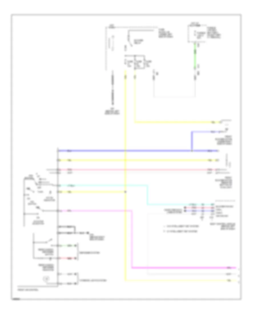
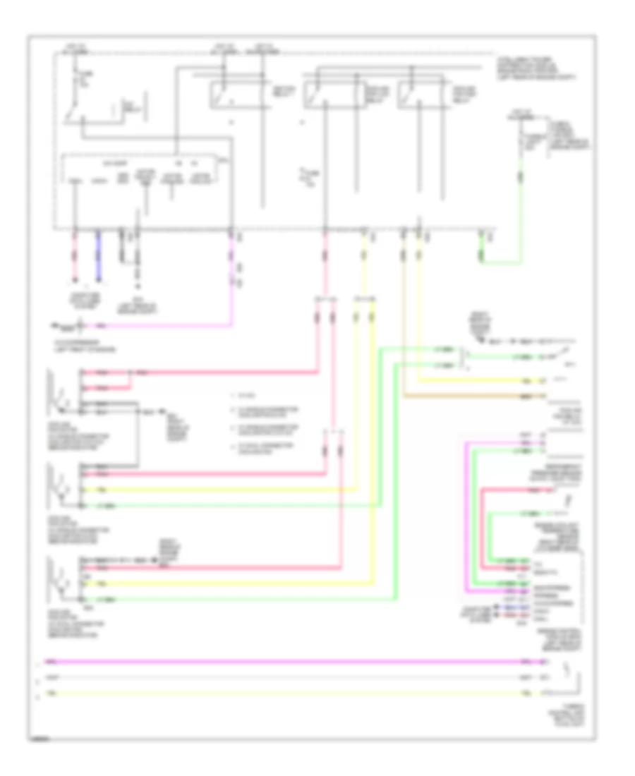
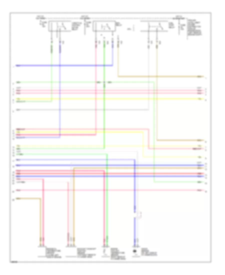
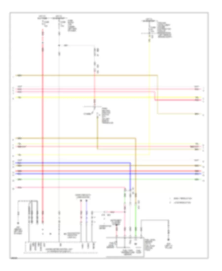
AIR CONDITIONING Manual A/C Wiring Diagram (1 of 2) for Nissan Versa S 2013 List of elements for Manual A/C Wiring Diagram (1 of 2) for Nissan Versa S 2013: 37 A/c & fan on switch A/c on indicator A/c switch Air con sw Blower fan sw Blower relay Body control module (behind left end of dash) Can-h Can-l Computer data lines system Defogger system E10 E11 Fan switch Front air control Front blower motor (under right side of dash) Front blower motor resistor (bottom of hvac unit) Fuse 10a Fuse 15a Fuse block j/b (under left end of dash) Fusible link box (battery) (on battery (+) terminal) Fusible link c 80a Hot at all times Hot in on Interior lights system M18 M57 (behind left side of dash) M78 M79 (behind right end of dash) M97 Off Pnk Rear window defogger indicator Rear window defogger switch Red W/ intelligent key system W/o intelligent key system Manual A/C Wiring Diagram (2 of 2) for Nissan Versa S 2013 List of elements for Manual A/C Wiring Diagram (2 of 2) for Nissan Versa S 2013: 51 (left front of engine) (right rear of engine compt) e24 A/c comp A/c compressor A/c relay Avcc2-pdpres Can-h Can-l Computer data lines system Cooling fan Cooling fan & a/c Cooling fan high relay Cooling fan low relay Cooling fan motor (w/ dual connector cooling fan) (behind radiator) Cooling fan motor (w/ single connector cooling fan & a/c) (behind radiator) Cooling fan motor (w/ single connector cooling fan w/o a/c) (behind radiator) Cooling fan relay (w/ a/c) Cooling fan w/o a/c Cpu E15 (left rear of engine compt) E16 E24 (right rear of engine compt) E32 E43 E45 E46 E55 Engine control module (ecm) (left rear of engine compt) Engine coolant temperature sensor (right rear of cylinder head) F11 F55 Fuse & fusible link box (left rear of engine compt) Fuse 10a Fusible link f 40a Gnd (sig) Gnd-pdpress Gnda-tw Hot at all times Hot in on or start Ignition relay 1 Intelligent power distribution module engine room (ipdm e/r) (left rear of engine compt) Motor fan-high Motor fan-low Motor fan-rly gnd Pdpress Pnk Refrigerant pressure sensor (on a/c liquid tank) Thermo control amp (bottom of hvac unit) W/ a/c W/ dual connector W/ single connector
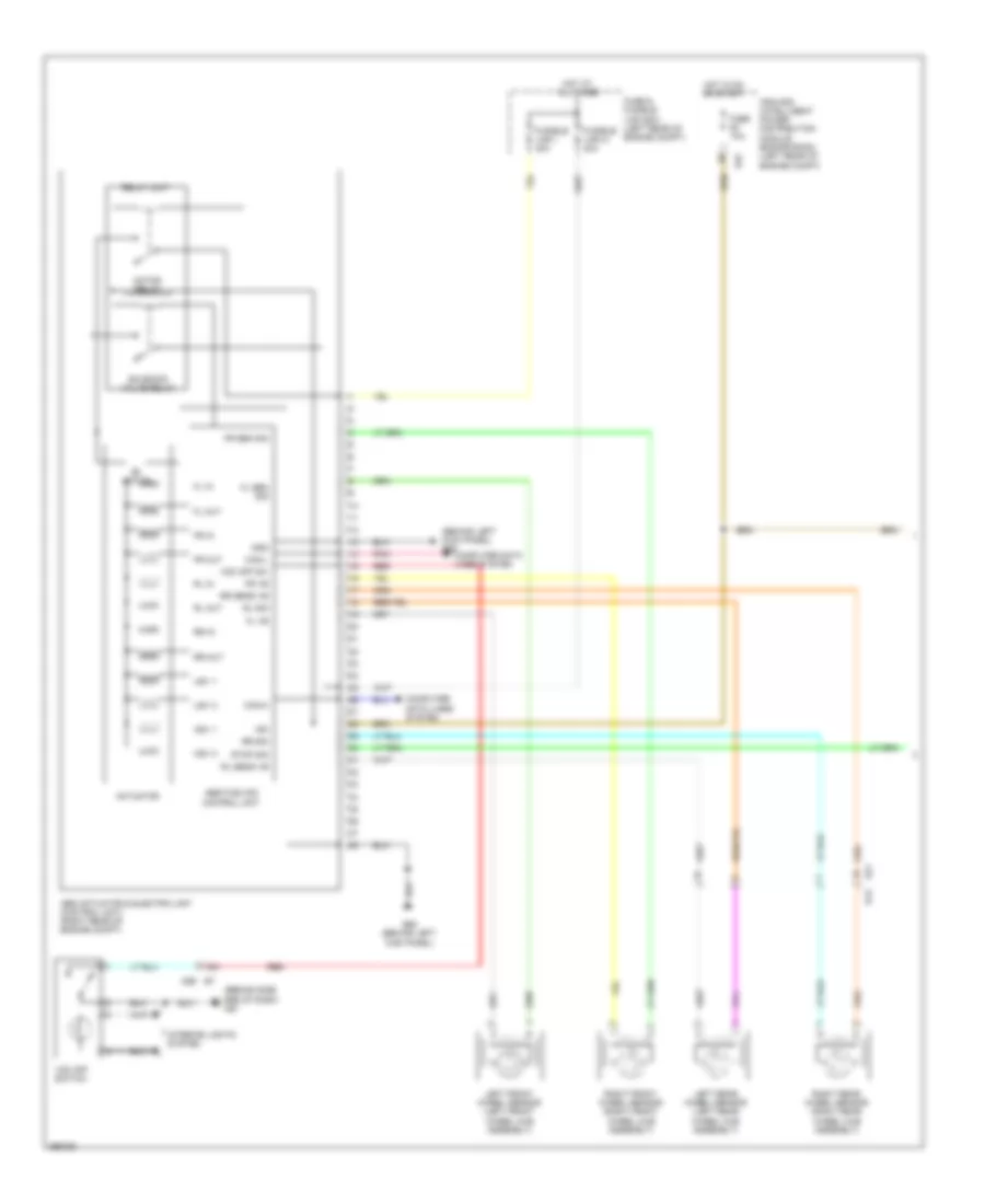
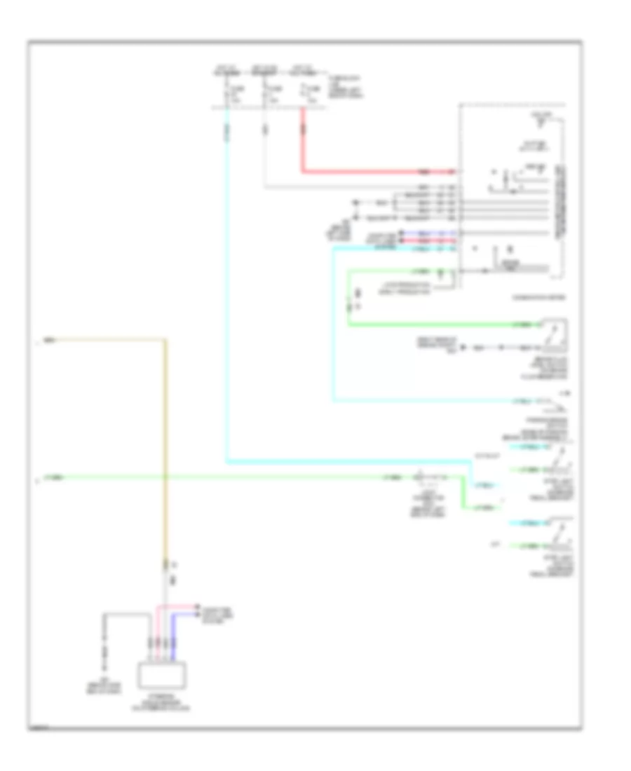
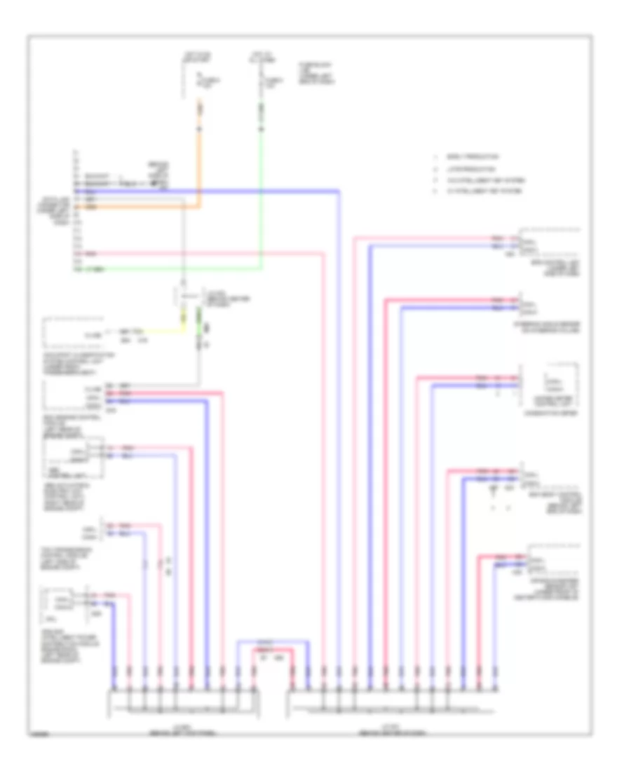
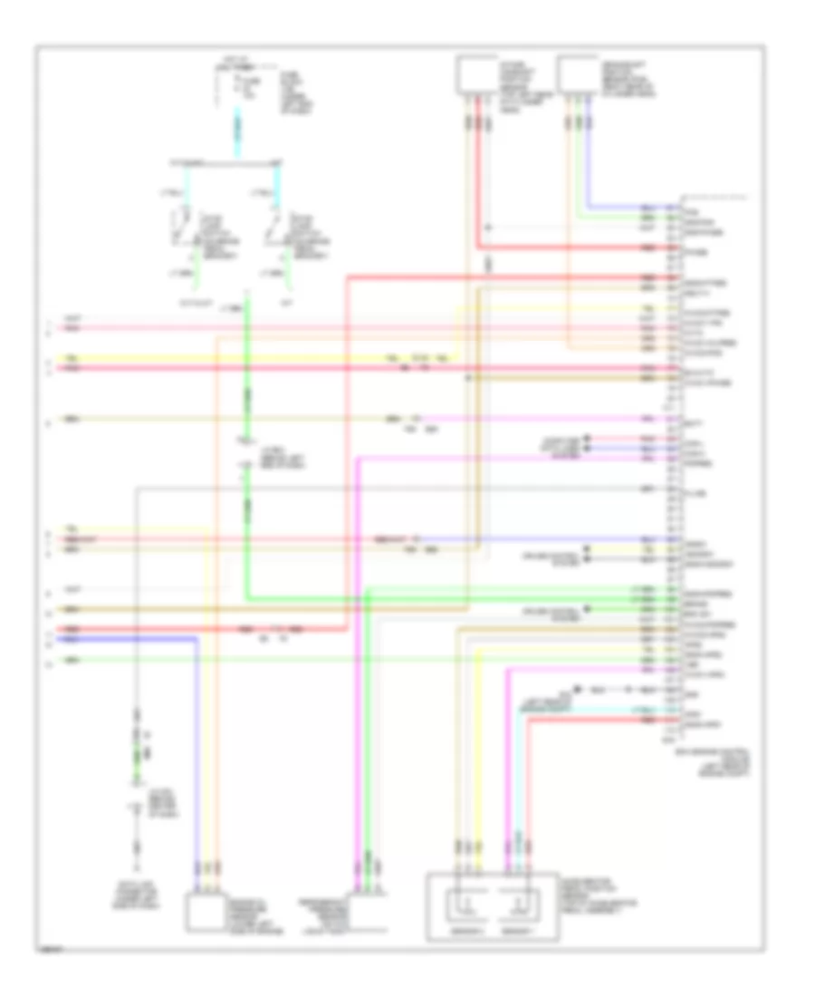
ANTI-LOCK BRAKES Anti-lock Brakes Wiring Diagram (1 of 2) for Nissan Versa S 2013 List of elements for Anti-lock Brakes Wiring Diagram (1 of 2) for Nissan Versa S 2013: 57 (behind left kick panel) e59 (behind side end of dash) m61 16a Abs actuator & electric unit (control unit) (right rear of engine compt) Abs/tcs/vdc control unit Actuator B12 Can-h Can-l Computer data lines system E21 E45 E60 (behind left kick panel) E7 m69 Fl in Fl out Fl sen sig Fl vb Fr in Fr out Fr sen sig Fr vb Fuse & fusible link box (left rear of engine compt) Fuse 10a Fusible link i 40a Fusible link m 40a Gnd Hot at all times Hot in on or start Hsv 1 Hsv 2 Ign Interior lights system Ipdm e/r (intelligent power distribution module engine room) (left rear of engine compt) Left front wheel sensor (left front wheel hub assembly) Left rear wheel sensor (left rear wheel hub assembly) Motor Motor relay Pnk Red Relay unit Right front wheel sensor (right front wheel hub assembly) Right rear wheel sensor (right rear wheel hub assembly) Rl in Rl out Rl sens vb Rl sig Rr in Rr out Rr sens vb Rr sig Solenoid valve relay Stop sig Usv 1 Usv 2 Vdc off sw Vdc off switch Anti-lock Brakes Wiring Diagram (2 of 2) for Nissan Versa S 2013 List of elements for Anti-lock Brakes Wiring Diagram (2 of 2) for Nissan Versa S 2013: 29 (right rear of engine compt) e24 (w/ information display) unified meter control unit 15a 18a Abs ind Brake fluid level switch (on brake fluid reservoir) Brake ind Combination meter Computer data lines system Cvt & a/t Early production Fuse 10a Fuse block (j/b) (under left end of dash) Hot at all times Hot in on or start Joint connector e-02 (behind left end of dash) Late production M/t M57 (behind left side of dash) M61 (behind side end of dash) M69 M69 e7 Parking brake switch (base of parking brake lever assembly) Pnk Red Slip ind Steering angle sensor (on steering column) Stop light switch (on brake pedal bracket) Vdc off ind
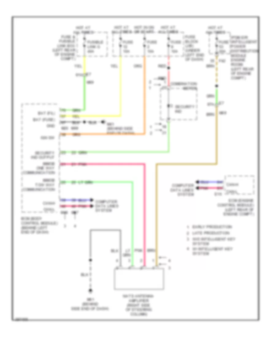
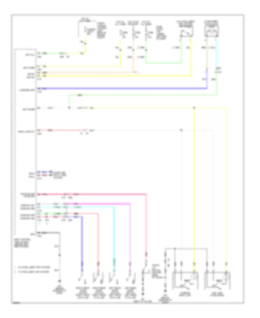
ANTI-THEFT Forced Entry Wiring Diagram, with Intelligent Key Unit (1 of 4) for Nissan Versa S 2013 List of elements for Forced Entry Wiring Diagram, with Intelligent Key Unit (1 of 4) for Nissan Versa S 2013: 90 (or red) 1o4 37a 38a red 39a e7 91a 92a 93a At device output B29 Back door antenna + Back door antenna - Batt saver output Battery (f/l) Bcm (body control module) (behind left end of dash) Brake sw 1 Brake sw 2 Can-h Can-l Canada Central door lock sw Central door unlock sw Computer data lines system Cvt shift selector (park position switch Door antenna (as) + Door antenna (as) - Door antenna (dr) + Door antenna (dr) - Door lock output Door sw (as) Door sw (dr) Door sw (rl) Door sw (rr) Door unlock common (dr) Door unlock output (as) Dr unlock output (rr, rl) Engine start switch Exterior lights system Fuse & fusible link box (left rear of engine compt) Fuse 10a Fuse block j/b (under left end of dash) Fusible link g 40a Gnd Hazard switch Hot at all times Hot in on or start Intelligent tuner Interior lights system J/c e02 (behind left end of dash) Key cylinder lock sw Key cylinder unlock sw Keyless tuner auto light Keyless tuner power sply Keyless tuner rssi Keyless tuner sig Left flasher output Left front door lock key cylinder switch Lock Luggage lamp output M100 M12 M61 (behind side end of dash) M69 M79 (behind right end of dash) M97 M98 M99 Outside key antenna (rear bumper) (behind center of rear bumper) Pnk Pow posi led (loc posi led) Red Request switch (as) Request switch (dr) Right flasher output Room antenna 1+ Room antenna 1- Room antenna 2+ Room antenna 2- Room antenna 3+ Room antenna 3- Room lamp output Security ind Sensor gnd Shift p posi park posi sw Smart keyless buzz output Stop lamp switch (on brake pedal bracket) Trunk, tailgate, fuel doors system Trunk/back dr open output Unlock Usa Forced Entry Wiring Diagram, with Intelligent Key Unit (2 of 4) for Nissan Versa S 2013 List of elements for Forced Entry Wiring Diagram, with Intelligent Key Unit (2 of 4) for Nissan Versa S 2013: 29 47a Computer data lines system Cpu D106 D113 D116 D16 D17 E15 (left rear of engine compt) E44 E46 E47 Horns system Inside key antenna (console) (under rear of center console) Inside key antenna (instrument center) (behind left center of dash) Intelligent key warning buzzer (left front of engine compt) Ipdm e/r (intelligent power distribution module engine room) (left rear of engine compt) J/c m05 (behind center of dash) Left front outside handle M61 (behind side end of dash) M69 M79 (behind right end of dash) M92 M93 Outside key antenna Pnk Red Request switch Right front outside handle Forced Entry Wiring Diagram, with Intelligent Key Unit (3 of 4) for Nissan Versa S 2013 List of elements for Forced Entry Wiring Diagram, with Intelligent Key Unit (3 of 4) for Nissan Versa S 2013: 23 (early production) combination meter B19 (left "c" pillar) B24 B29 Buzzer Canada Computer data lines system Inside key antenna (trunk room) (center front of luggage compt) Key ind Left front door switch (left front "b" pillar) Left rear door switch (left rear "c" pillar) M12 M16 M79 (behind right end of dash) Pnk Red Remote keyless entry receiver (behind right side of dash) Right front door switch (right front "b" pillar) Right rear door switch (right rear "c" pillar) Security ind Shield Unified meter control unit (w/ information display) Usa Forced Entry Wiring Diagram, with Intelligent Key Unit (4 of 4) for Nissan Versa S 2013 List of elements for Forced Entry Wiring Diagram, with Intelligent Key Unit (4 of 4) for Nissan Versa S 2013: 28 (behind center end of dash) j/c m05 Acc/on B11 B23 B29 Cpu D115 D201 D301 Interior lights system J/c m05 (behind center end of dash) Left front door lock actuator Left rear door lock actuator Lock M12 M15 M57 (behind left side of dash) M61 (behind side end of dash) M79 (behind right end of dash) M81 Main power window & door lock/unlock switch Push switch Push-button ignition switch Red Right front door lock actuator Right power window & door lock/unlock switch Right rear door lock actuator Unlock Forced Entry Wiring Diagram, without Intelligent Key Unit for Nissan Versa S 2013 List of elements for Forced Entry Wiring Diagram, without Intelligent Key Unit for Nissan Versa S 2013: 88 Acc sw Audio/dongle B11 B23 B24 B29 Bat (f/l) Bat (fuse) Batt saver Bcm (body control module) (behind left end of dash) Can- h Can- l Can-h Can-l security ind output Cdl lock sw Cdl unlock sw Combination meter Computer data lines system Cpu D115 D201 D301 Dongle unit (behind left center of dash) Door sw (as) Door sw (dr) Door sw (rl) Door sw (rr) Dr lk output Dr unlk out (all) Dr unlk out (dr) Dtrl E46 E7 91a Early production Exterior lights system Fuse & fusible link box (left rear of engine compt) Fuse 10a Fuse block (j/b) (under left end of dash) Fusible link g 40a Gnd H/lp hi H/lp lo Headlights system Horn rly Horns system Hot at all times Hot in on or acc Interior lights system Ipdm e/r (intelligent power distribution module engine room) (left rear of engine compt) Key cyl lk sw Key cyl unlk sw Key sw Key switch Keyless & auto light sens gnd Late production Left front door lock actuator Left front door lock key cylinder switch Left front door switch (left front "b" pillar) Left rear door lock actuator Left rear door switch (left rear "c" pillar) Lock Lt flasher out Luggage lamp out M12 M15 M16 M18 M19 M20 M57 (behind left side of dash) M61 (behind side end of dash) M69 M79 (behind right end of dash) M81 Main power window & door lock/ unlock switch Pnk Red Remote keyless entry receiver (behind right side of dash) Right front door lock actuator Right front door switch (right front "b" pillar) Right power window & door lock/ unlock switch Right rear door lock actuator Right rear door switch (right rear "c" pillar) Room lamp output Rt flasher out Security ind Un- lock Unlock Immobilizer Wiring Diagram for Nissan Versa S 2013 List of elements for Immobilizer Wiring Diagram for Nissan Versa S 2013: 39 Bat (f/l) Bat (fuse) Bcm (body control module) (behind left end of dash) Can-h Can-l Combination meter Computer data lines system E16 E7 91a E7 97a Early production Ecm (engine control module) (left rear of engine compt) F42 Fuse & fusible link box (left rear of engine compt) Fuse 10a Fuse 20a Fuse block (j/b) (under left end of dash) Fusible link g 40a Gnd Hot at all times Hot in on or start Ign sw Immob one way communication Immob tow way communication Ipdm e/r (intelligent power distribution module engine room) (left rear of engine compt) Late production M18 M20 M61 (behind side end of dash) M69 M97 M99 Nats antenna amplifier (right side of steering column) Pnk Red Security ind Security ind output W/ intelligent key system W/o intelligent key system
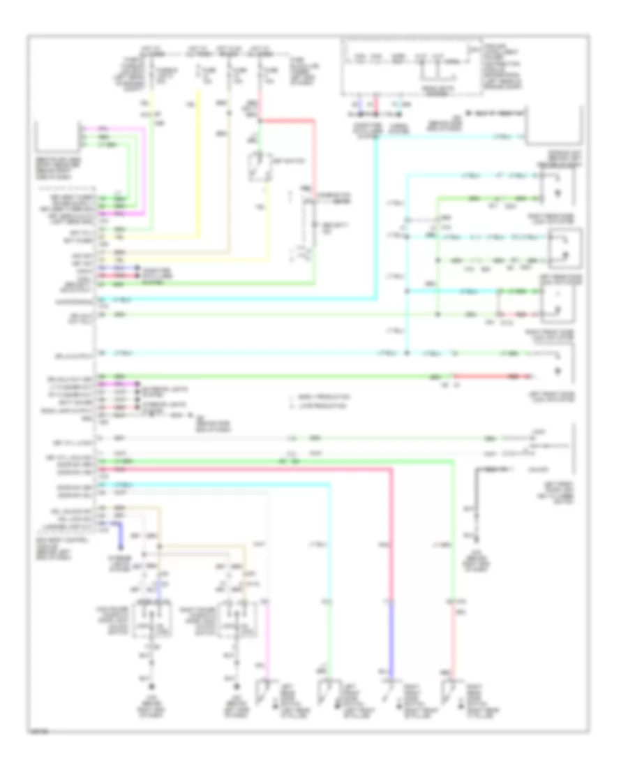
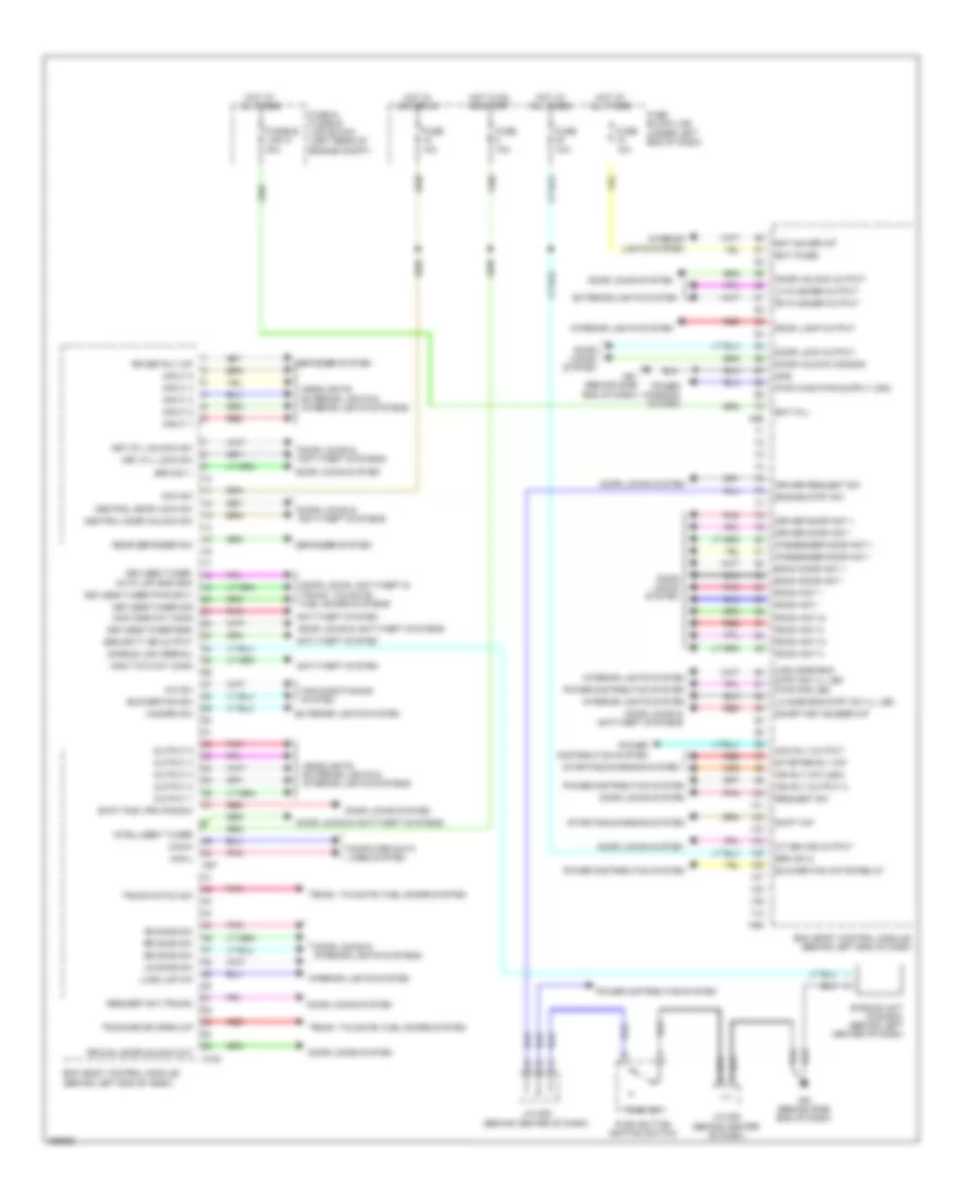
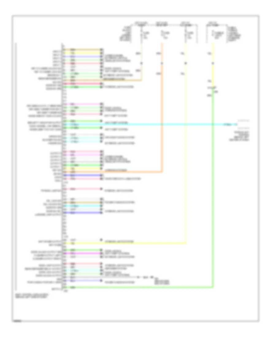
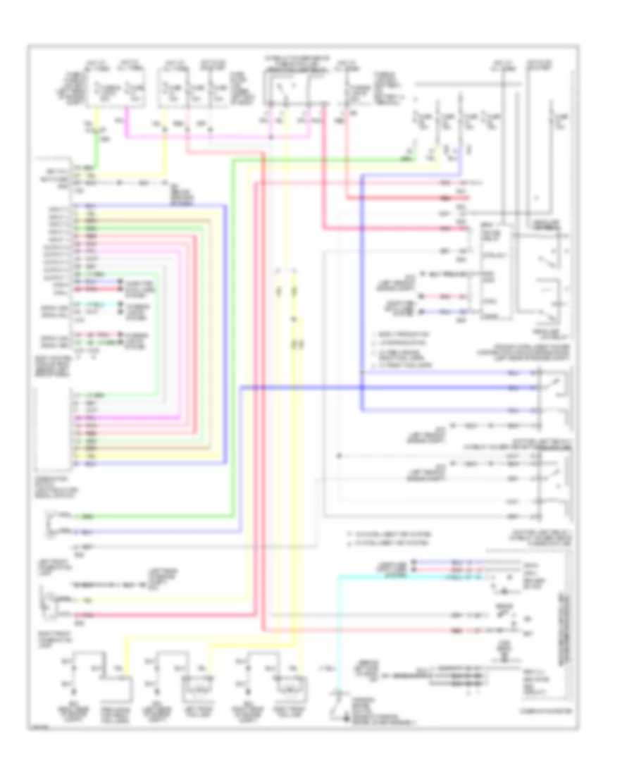
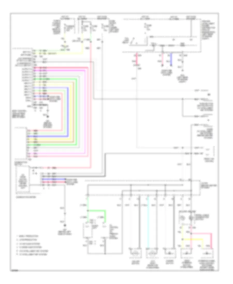
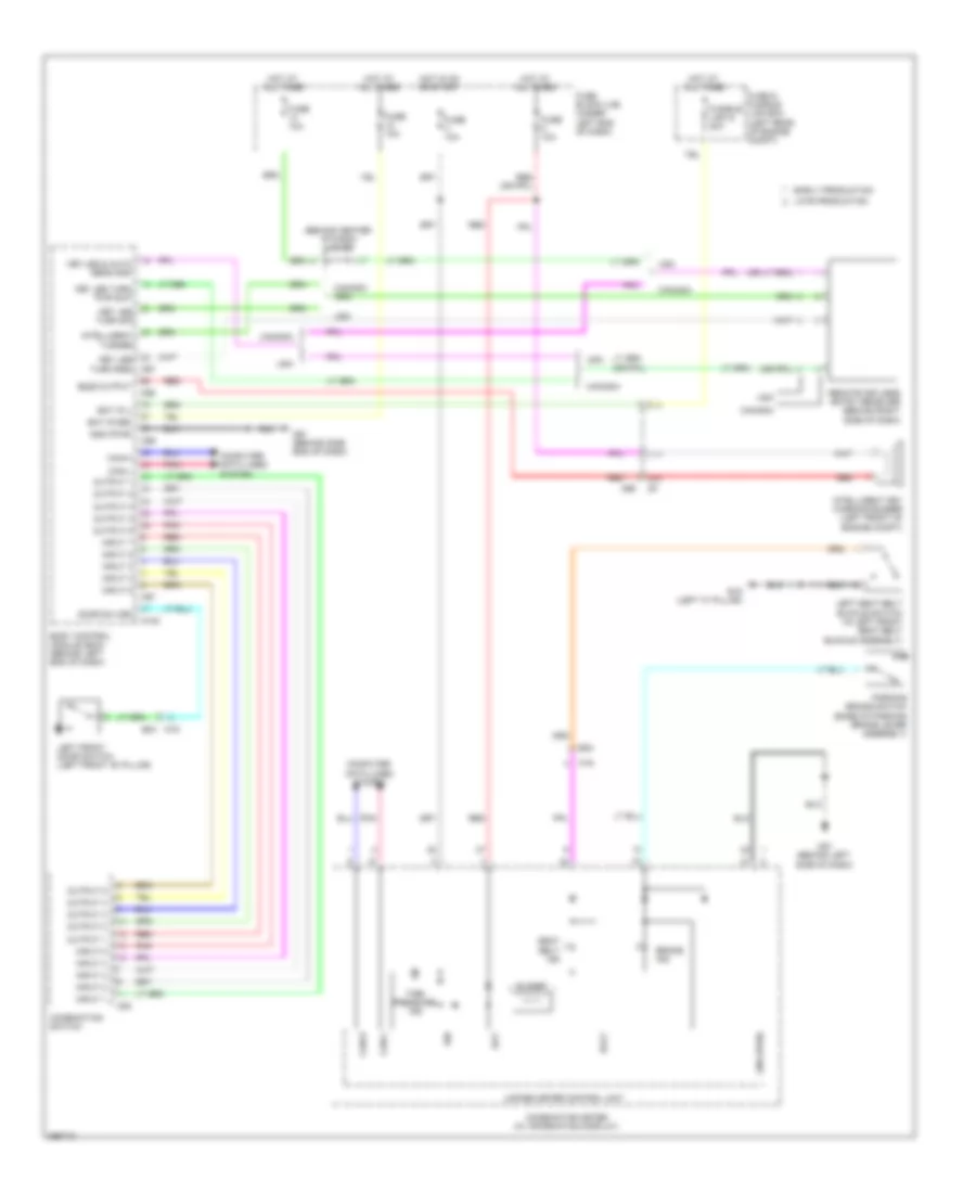
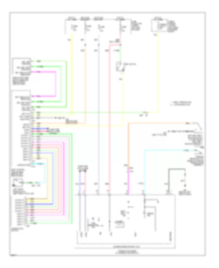
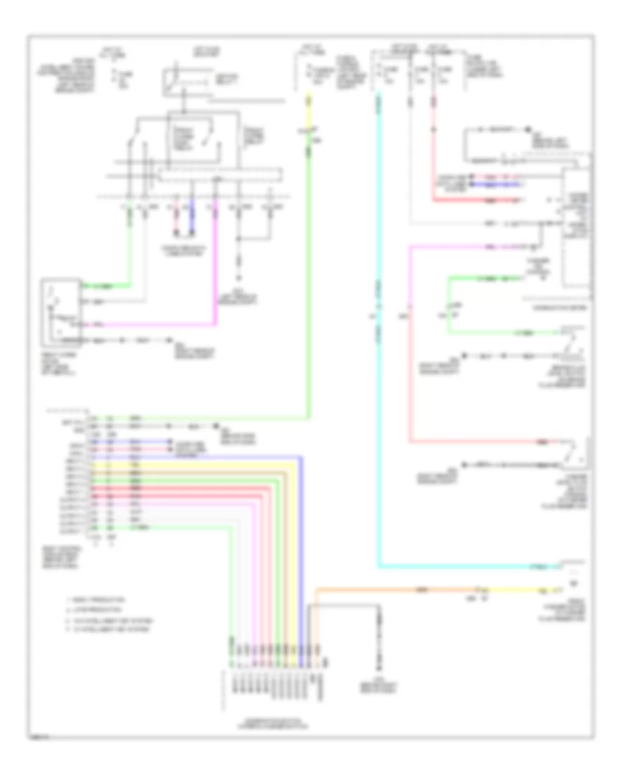
BODY CONTROL MODULES Body Control Modules Wiring Diagram, with Intelligent Key for Nissan Versa S 2013 List of elements for Body Control Modules Wiring Diagram, with Intelligent Key for Nissan Versa S 2013: 114 A/c sw Acc rly output Acc sw Air conditioning system Anti-theft system As door sw At device output Auto lmp sns gnd Back door ant + Back door ant - Bat (f/l) Bat (fuse) Bat saver o/p Bcm (body control module) (behind left end of dash) Blower fan motor relay Blower fan sw Brk sw 1 Brk sw 2 Can-h Can-l Central door lock sw Central door unlock sw Computer data lines system Defogger system Dongle link (serial) Dongle unit (canada) (behind left center of dash) Door lock output Door locks & anti-theft systems Door locks & interior lights systems Door locks system Door locks, anti-theft & trunk, tailgate, fuel doors systems Door unlock common Door unlock output Dr door sw Driver door ant + Driver door ant - Driver request sw Engine strt sw Exterior lights system Fuse & fusible link block (left rear of engine compt) Fuse 10a Fuse block (j/b) (under left end of dash) Fusible link g 40a Gnd Hazard sw Headlights, exterior lights & interior lights systems High side eng strt sw ill led Hot at all times Hot in acc or on Hot in on or start Ign rly o/p (usm) Ign rly output 2 Immo one way comm Immo two way comm Input 1 Input 2 Input 3 Input 4 Input 5 Intelligent tuner Interior lights system J/c m05 (behind center of dash) Key cyl lock sw Key cyl unlock sw Keyless tuner pwr sply Keyless tuner rssi Keyless tuner sig Keyless tuner, Lh flasher output Lo side eng strt sw ill led Lr door sw Lugg lmp o/p M100 M61 (behind side end of dash) M97 M98 M99 Output 1 Output 2 Output 3 Output 4 Output 5 Passenger door ant + Passenger door ant - Pnk Power distribution system Power windows system Push button ignition switch Push sw Pwr pos led Rear defogger sw Red Request sw Request sw (trunk) Rh flasher output Room ant + Room ant - Room ant 2+ Room ant 2- Room ant 3+ Room ant 3- Room lamp output Rr & rl door unlock out Rr def rly o/p Rr door sw Security ind output Shift n/p Shift pos, prk pos sw Smart-key buzzer o/p Starter rly o/p Starting/charging system Trunk hatch sw Trunk, tailgate, fuel doors system Trunk/bk dr open o/p Body Control Modules Wiring Diagram, without Intelligent Key for Nissan Versa S 2013 List of elements for Body Control Modules Wiring Diagram, without Intelligent Key for Nissan Versa S 2013: 77 Acc sw Air conditioning system Aircon sw Anti-theft system Audio /dongel link (serial) Bat (f/l) Bat (fuse) Bat saver output Blower fan sw Body control module (bcm) (behind left side of dash) Brake sw 1 Can-h Can-l Cdl lock sw Cdl unlock sw Computer data lines system Defogger system Dongle unit (canada) (behind left center of dash) Door lock output Door locks & anti-theft systems Door locks & warning systems Door sw (as) Door sw (dr) Door sw (rl) Door sw (rr) Door unlock output Door unlock output (dr) E7 91a Exterior lights system Flasher output (left) Flasher output (right) Fuse & fusible link box (left rear of engine compt) Fuse 10a Fuse block (j/b) (under left end of dash) Fusible link g 40a Gnd Hazard sw Hot at all times Hot in acc or on Hot in on or start Ign sw Immob oneway comm (clock) Immobilizer two way comm Input 1 Input 2 Input 3 Input 4 Input 5 Interior lights system Key cylinder lock sw Key cylinder unlock sw Key sw Keyless & auto lt sens gnd Keyless turner pwr sply Keyless turner sig Luggage lamp output M18 M19 M20 M61 (behind side end of dash) M69 Output 1 Output 2 Output 3 Output 4 Output 5 Pnk Power windows system Pwr window pwr sply (rap) Rear defogger relay output Rear defogger sw Red Room lamp output Security indicator output Tr room lamp sw Warning systems Wiper/washer, exterior lights & headlights systems
COMPUTER DATA LINES Computer Data Lines Wiring Diagram for Nissan Versa S 2013 List of elements for Computer Data Lines Wiring Diagram for Nissan Versa S 2013: 46 (behind center of dash) (behind left kick panel) (behind left side of dash) m57 19a 20a 21a Abs actuator & electric unit (control unit) (right rear of engine compt) Abs control unit Air bag diagnosis sensor unit (under front of center floor console) B24 Bcm (body control module) (behind left end of dash) Can-h Can-l Combination meter Cpu Data link connector (under left side of dash) E16 E46 Early production Ecm (engine control module) (left rear of engine compt) Eps control unit (under left side of dash) F8 e8 Fuse 5 10a Fuse 8 10a Fuse block (j/b) (under left end of dash) Hot at all times Hot in on or start Ipdm e/r (intelligent power distribution module engine room) (left rear of engine compt) J/c e03 J/c m01 J/c m03 (behind center of dash) K-line Late production M16 M18 M35 M53 M69 M97 Occupant classification system control unit (under front passenger's seat) Pnk Steering angle sensor (on steering column) Tcm (transmission control module) (left side of engine compt) Unified meter control unit W/ intelligent key system W/o intelligent key system
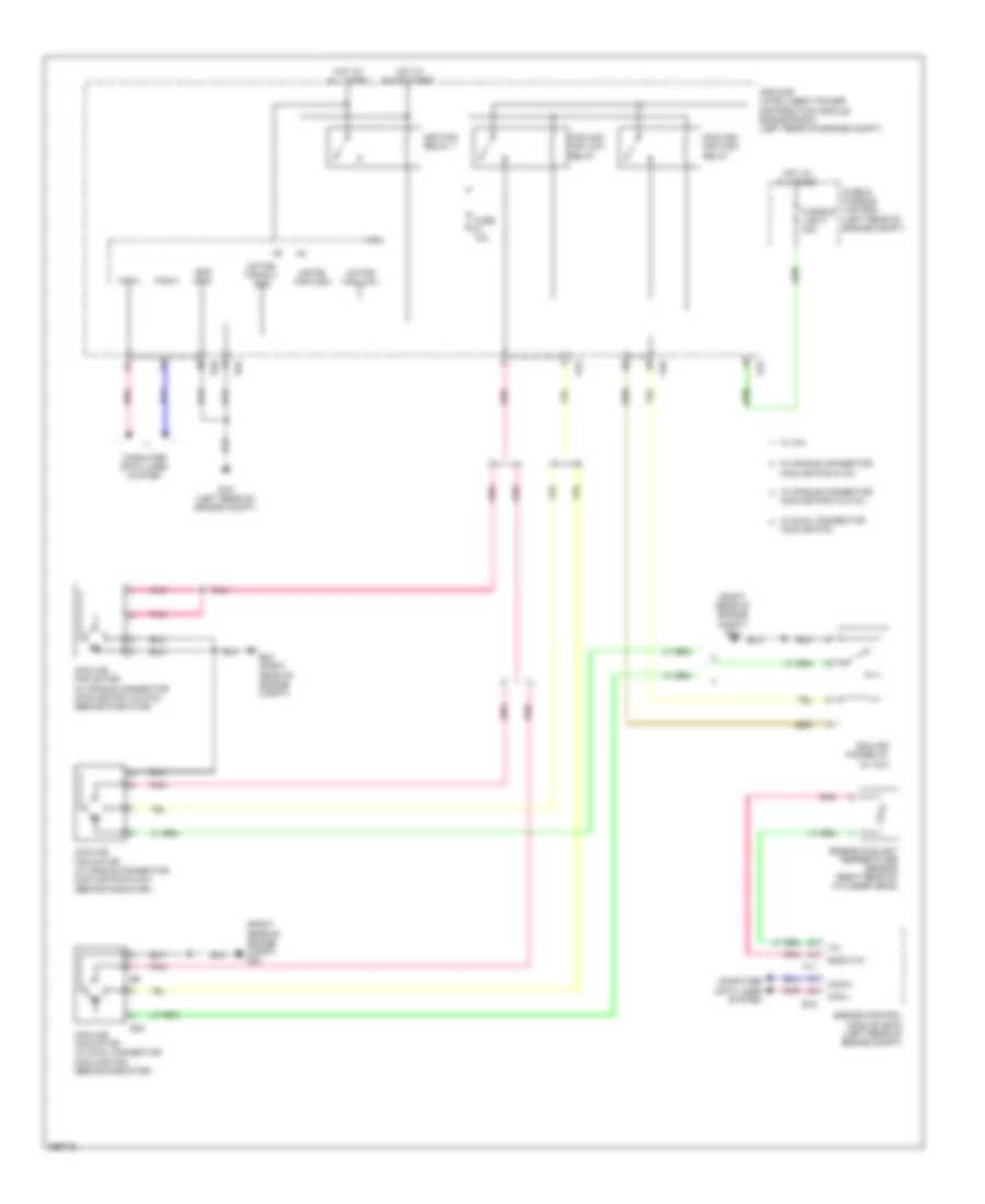
COOLING FAN Cooling Fan Wiring Diagram for Nissan Versa S 2013 List of elements for Cooling Fan Wiring Diagram for Nissan Versa S 2013: 40 (right rear of engine compt) e24 Can-h Can-l Computer data lines system Cooling fan Cooling fan & a/c Cooling fan high relay Cooling fan low relay Cooling fan motor (w/ dual connector cooling fan) (behind radiator) Cooling fan motor (w/ single connector cooling fan & a/c) (behind radiator) Cooling fan motor (w/ single connector cooling fan w/o a/c) (behind radiator) Cooling fan relay (w/ a/c) Cooling fan w/o a/c Cpu E15 (left rear of engine compt) E16 E24 (right rear of engine compt) E32 E43 E45 E46 Engine control module (ecm) (left rear of engine compt) Engine coolant temperature sensor (right rear of cylinder head) F11 Fuse & fusible link box (left rear of engine compt) Fuse 10a Fusible link f 40a Gnd (sig) Gnda-tw Hot at all times Hot in on or start Ignition relay 1 Ipdm e/r (intelligent power distribution module engine room) (left rear of engine compt) Motor fan-high Motor fan-low Motor fan-rly gnd Pnk W/ a/c W/ dual connector W/ single connector
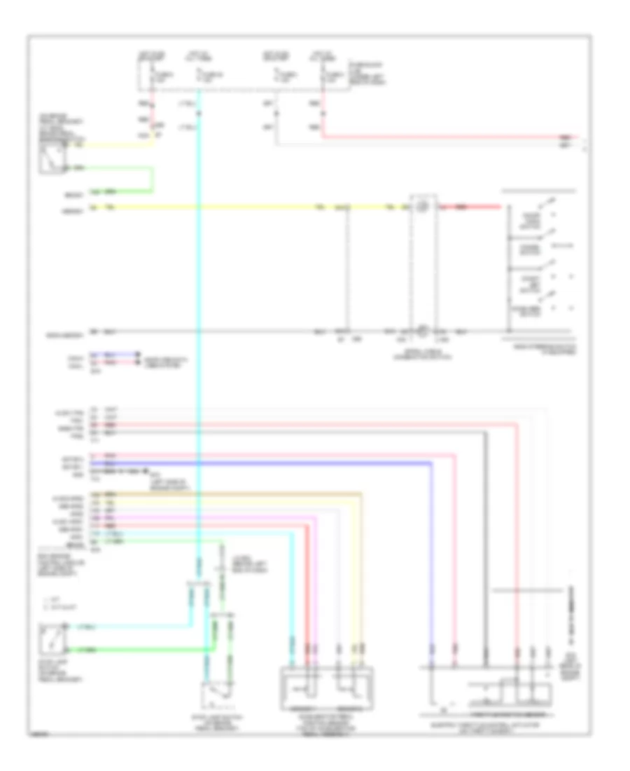
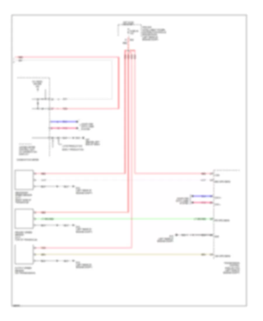
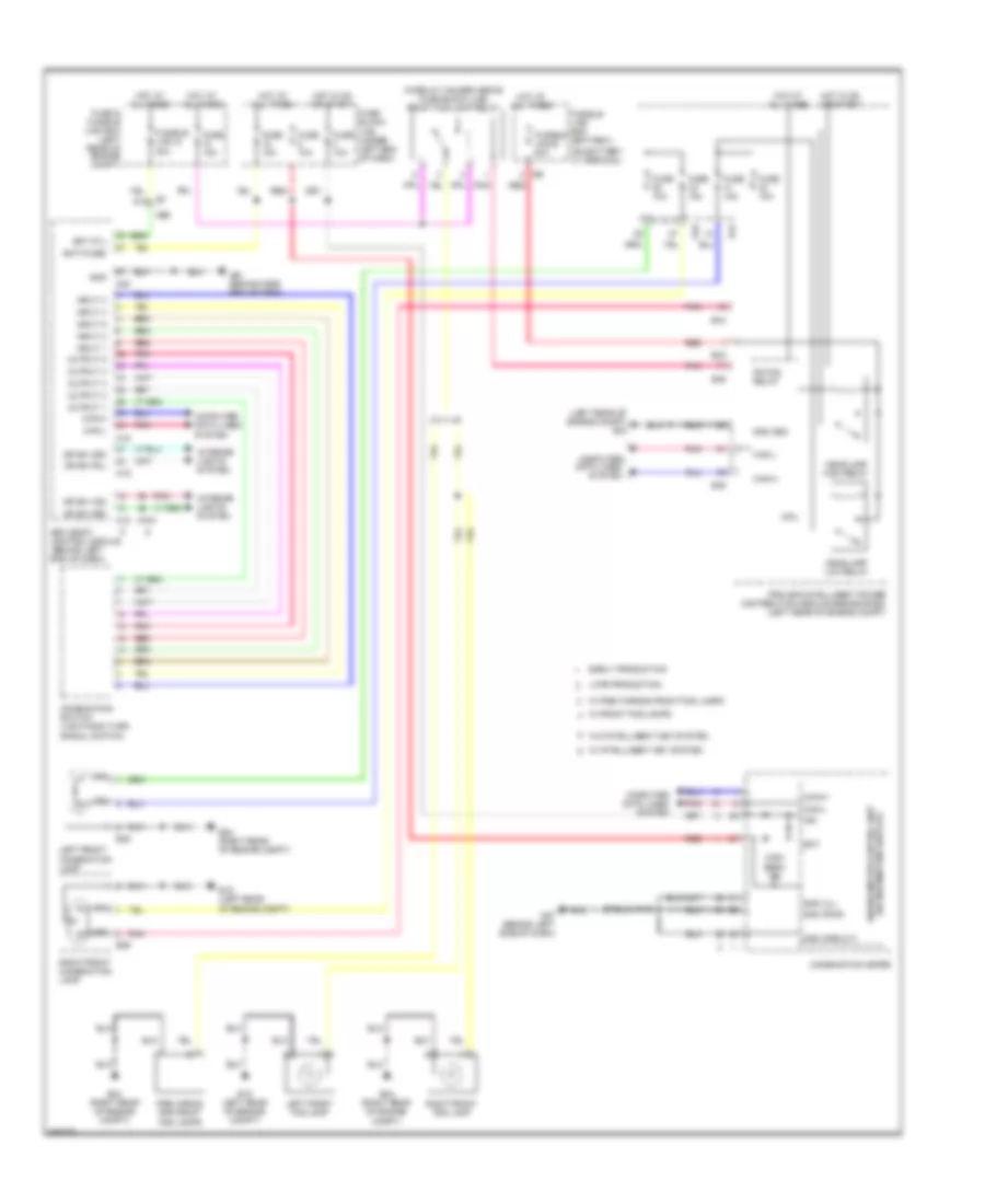
CRUISE CONTROL Cruise Control Wiring Diagram (1 of 2) for Nissan Versa S 2013 List of elements for Cruise Control Wiring Diagram (1 of 2) for Nissan Versa S 2013: 60 (left side of (on brake pedal bracket) (w/ ascd) brake pedal position switch 100a 94a 99a Accel/res switch Accelerator pedal position sensor (top of accelerator pedal assembly) Aps1 Aps2 Ascd steering switch (if equipped) Ascdsw Avcc1-aps1 Avcc1-tps Avcc2-aps2 Bncsw Brake Can-h Can-l Cancel switch Coast/ set switch Computer data lines system Cvt & a/t E15 E15 (left rear of engine compt) E16 Ecm (engine control module) (left side of engine compt) Electric throttle control actuator (on throttle body) Engine compt) F10 F11 Fuse 3 10a Fuse 30 10a Fuse 5 10a Fuse 8 10a Fuse block (j/b) (under left end of dash) Gnd Gnd-aps1 Gnd-aps2 Gnda-ascdsw Gnda-tps Hot at all times Hot in on or start J/c e02 (behind left end of dash) M/t M30 M69 M88 Motor 1 Motor 2 Nca On/off (main) switch Pnk Red Sensor 1 Sensor 2 Spiral cable (combination switch) Stop lamp switch (on brake pedal bracket) Throttle position sensor Tps1 Tps2 Cruise Control Wiring Diagram (2 of 2) for Nissan Versa S 2013 List of elements for Cruise Control Wiring Diagram (2 of 2) for Nissan Versa S 2013: 25 (w/ ascd) cruise ind Can h Can l Combination meter Computer data lines system E15 (left rear of engine compt) E45 Early production Fuse 49 10a Gnd Hot in on or start Ipdm e/r (intelligent power distribution module engine room) (left rear of engine compt) Late production M57 (behind left end of dash) Output speed sensor (on transmission) Pnk Pri spd sens Primary speed sensor (cvt) (top of transaxle) Red Sec spd sens Secondary speed sensor (cvt) (right side of transaxle) Transmission control module (tcm) (left side of engine compt) Unified meter control unit (w/ information display) Veh spd sens Vign
DEFOGGERS Defoggers Wiring Diagram for Nissan Versa S 2013 List of elements for Defoggers Wiring Diagram for Nissan Versa S 2013: 50 91a B28 B42 B43 (left front of luggage compt) B46 Bat (f/l) Bcm (body control module) (behind left end of dash) Can-h Can-l Canada Computer data lines system D115 D115 m81 D2 m8 Door Door mirror defogger Front air control Fuse & fusible link box (left rear of engine compt) Fuse 10a Fuse 20a Fuse block (j/b) (under left end of dash) Fusible link g 40a Gnd Hot at all times Hot in on or start Ig sw J/c m01 (behind center of dash) Left door mirror M10 M11 M18 M20 M61 (behind side of dash) M69 M79 (behind right end of dash) M81 M97 M99 Mirror defogger Pnk Rear window defogger Rear window defogger indicator Rear window defogger relay (in relay holder above fuse block (j/b)) Rear window defogger switch Red Right door mirror Rr def relay out Rr def sw W/ intelligent key W/o intelligent key
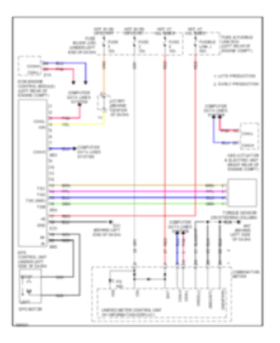
ELECTRONIC POWER STEERING Electronic Power Steering Wiring Diagram for Nissan Versa S 2013 List of elements for Electronic Power Steering Wiring Diagram for Nissan Versa S 2013: 42 Abs actuator & electric unit (right rear of engine compt) Bat Can-h Can-l Combination meter Computer data lines system E16 E23 E61 (behind left end of dash) Early production Ecm (engine control module) (left rear of engine compt) Eps control unit (under left side of dash) Eps motor Fuse & fusible link box (left rear of engine compt) Fuse 10a Fuse block (j/b) (under left end of dash) Fusible link j 60a Gnd Gnd(ckt) Gnd(ill) Gnd(pwr) Hot at all times Hot in on or start Ign J/c m01 (behind center of dash) Late production Left M53 M54 M57 (behind left side of dash) M60 Nca Pnk Ps ind Red Right Torque sensor (on steering column) Tse (gnd) Tsm Tss Tsv Unified meter control unit (w/ information display)
ENGINE PERFORMANCE
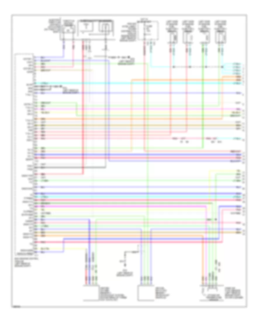
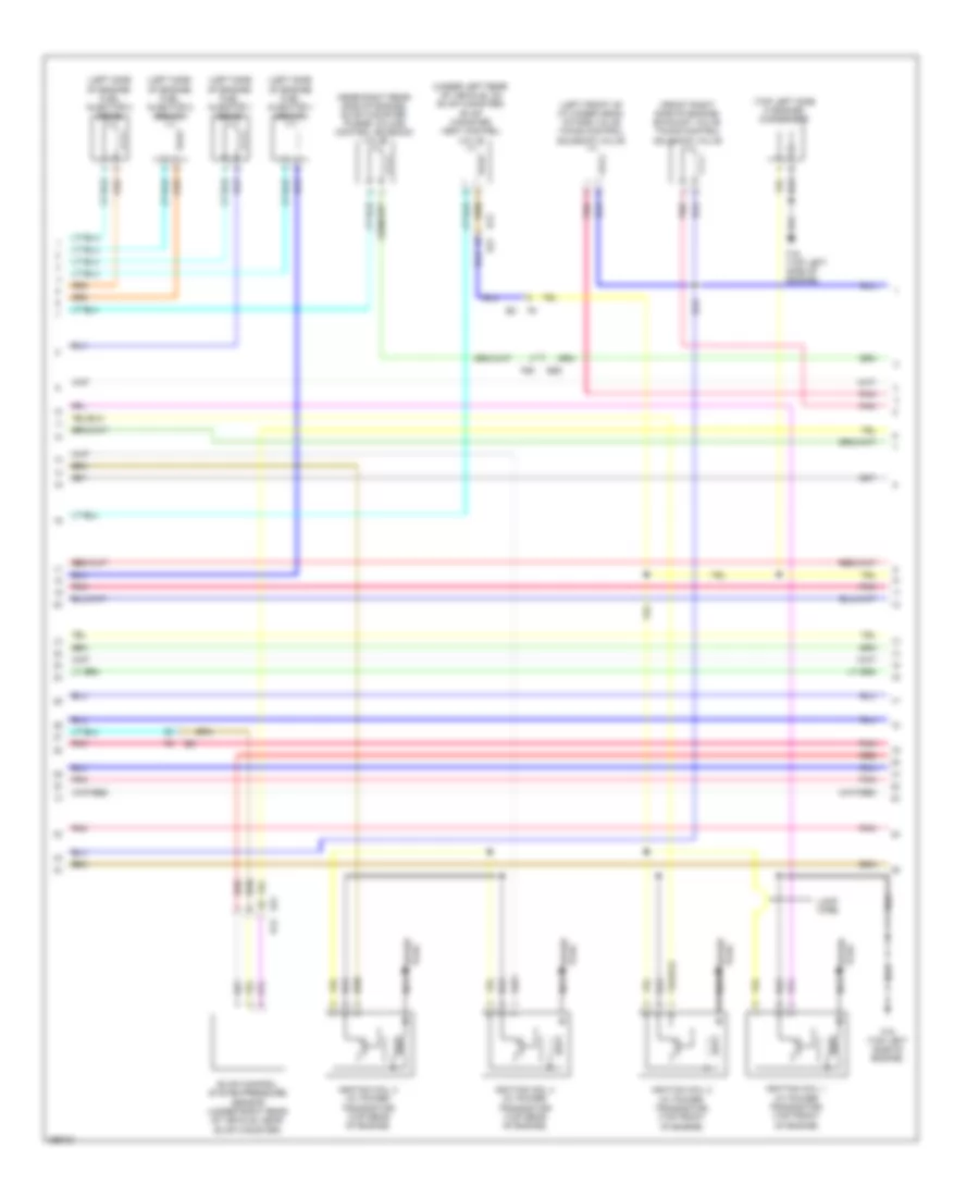
1.6L 1.6L, Engine Performance Wiring Diagram (1 of 5) for Nissan Versa S 2013 List of elements for 1.6L, Engine Performance Wiring Diagram (1 of 5) for Nissan Versa S 2013: 70 (left side of engine) fuel injector 3 (front) (left side of engine) fuel injector 3 (rear) (left side of engine) fuel injector 4 (front) (left side of engine) fuel injector 4 (rear) Af+ Af- Afh Air fuel ratio (a/f) sensor 1 (on exhaust manifold) B12 Cdcv E15 (left rear of engine compt) E21 E55 Ecm (engine control module) (left rear of engine compt) Electric throttle control actuator (on throttle body) Evap Ex-phase F10 F11 F42 F43 F55 F8 e8 Fpr Ftpres Fuse 10a Gnd Gnda-knk Gnda-o2sr Gnda-oilpres Gnda-ta Gnda-tf Gnda-to Gnda-tps Gnda-tw Heated oxygen sensor 2 (on exhaust system, downstream of three way catalyst) Hot in on or start Ign 1 Ign 2 Ign 3 Ign 4 Inj 1 Inj 2 Inj 3 Inj 4 Intake air temperature sensor Ipdm e/r (intelligent power distribution module engine room) (left rear of engine compt) Knk Mass air flow sensor (left rear of engine compt, on air cleaner) Motor 1 Motor 2 Motrly Nca O2hr O2ssr Oilpres Pnk Qa+ Qa- Red Ssoff T-inj 1 T-inj 2 T-inj 3 T-inj 4 Throttle control motor Throttle position sensor Tps1 Tps2 Vmot 1.6L, Engine Performance Wiring Diagram (2 of 5) for Nissan Versa S 2013 List of elements for 1.6L, Engine Performance Wiring Diagram (2 of 5) for Nissan Versa S 2013: 26 (front right side of engine) exhaust valve timing control solenoid valve (left front of cylinder head) intake valve timing control solenoid valve (left side of engine) fuel injector 1 (front) (left side of engine) fuel injector 1 (rear) (left side of engine) fuel injector 2 (front) (left side of engine) fuel injector 2 (rear) (near right rear side of engine) evap canister purge volume control solenoid valve (top left side if engine) condenser (under left rear of vehicle, on evap canister) evap canister vent control valve B12 E21 E21 b12 E55 Evap control system pressure sensor (under right rear of vehicle, near evap canister) F16 (top left side of engine) F55 Ignition coil 1 (w/ power transistor) (top front of engine) Ignition coil 2 (w/ power transistor) (top front of engine) Ignition coil 3 (w/ power transistor) (top rear of engine) Ignition coil 4 (w/ power transistor) (top rear of engine) Loop wire Nca Plug spark Pnk Red Spark plug 1.6L, Engine Performance Wiring Diagram (3 of 5) for Nissan Versa S 2013 List of elements for 1.6L, Engine Performance Wiring Diagram (3 of 5) for Nissan Versa S 2013: 18 Cpu E44 Ecm relay Engine coolant temperature sensor (right rear of cylinder head) Engine oil temperature sensor (lower left side of engine) Exhaust camshaft position sensor (top right rear of cylinder head) F42 F43 Fuel pump relay Fuse 15a Fuse 20a Hot at all times Hot in on or start Ipdm e/r (intelligent power distribution module engine room) (left rear of engine compt) Knock sensor (on left side of cylinder block) Pnk Red Throttle control motor relay 1.6L, Engine Performance Wiring Diagram (4 of 5) for Nissan Versa S 2013 List of elements for 1.6L, Engine Performance Wiring Diagram (4 of 5) for Nissan Versa S 2013: 39 (power) gnd B12 B19 (left "c" pillar) B24 Bat Can-h Can-l Combination meter Computer data E21 E42 E55 Early production F55 Fm gnd Fuel level sensor Fuel level sensor unit & fuel pump (on fuel tank) Fuel pump Fuel tank temperature sensor Fuse 10a Fuse block (j/b) (under left end of dash) Gnd (circuit) Gnd(ill) Hot at all times Hot in on or start Ign Instrument cluster system Ipdm e/r (intelligent power distribution module engine room) (left rear of engine compt) Late production Lines system M16 M57 (behind left end of dash) M69 Malfunction indicator lamp (mil) Others Park/ neutral position switch (m/t) (on left side of transaxle) Pnk Red Unified meter control unit (w/ information display) 1.6L, Engine Performance Wiring Diagram (5 of 5) for Nissan Versa S 2013 List of elements for 1.6L, Engine Performance Wiring Diagram (5 of 5) for Nissan Versa S 2013: 60 Accelerator pedal position sensor (top of accelerator pedal assembly) Aps1 Aps2 Ascdsw Avcc1-aps1 Avcc1-oilpres Avcc1-phase Avcc1-tps Avcc2-aps2 Avcc2-ftpes Avcc2-pdpres Avcc2-pos Batt Bnc sw Brake Can-h Can-l Computer data lines system Crankshaft position sensor (pos) (right rear of cylinder head) Cruise control system Cvt & a/t Cvtc Data link connector (under left side of dash) E15 (left rear of engine compt) E16 E55 Ecm (engine control module) (left rear of engine compt) Engine oil pressure sensor (lower left side of engine) Ex-cvtc F11 F55 Fuse 10a Fuse block (j/b) (under left end of dash) Gnd Gnd-phase Gnd-pos Gnda-aps1 Gnda-aps2 Gnda-ascdsw Gnda-ftpes Gnda-pdpres Hot at all times Ignsw Intake camshaft position sensor (top left rear of cylinder head) J/c e02 (behind left end of dash) J/c m03 (behind center of dash) K-line M/t M69 Neut-h Pdpres Phase Pnk Pos Red Refrigerant pressure sensor (on a/c liquid tank) Sensor 1 Sensor 2 Stop lamp switch (on brake pedal bracket) Vbr
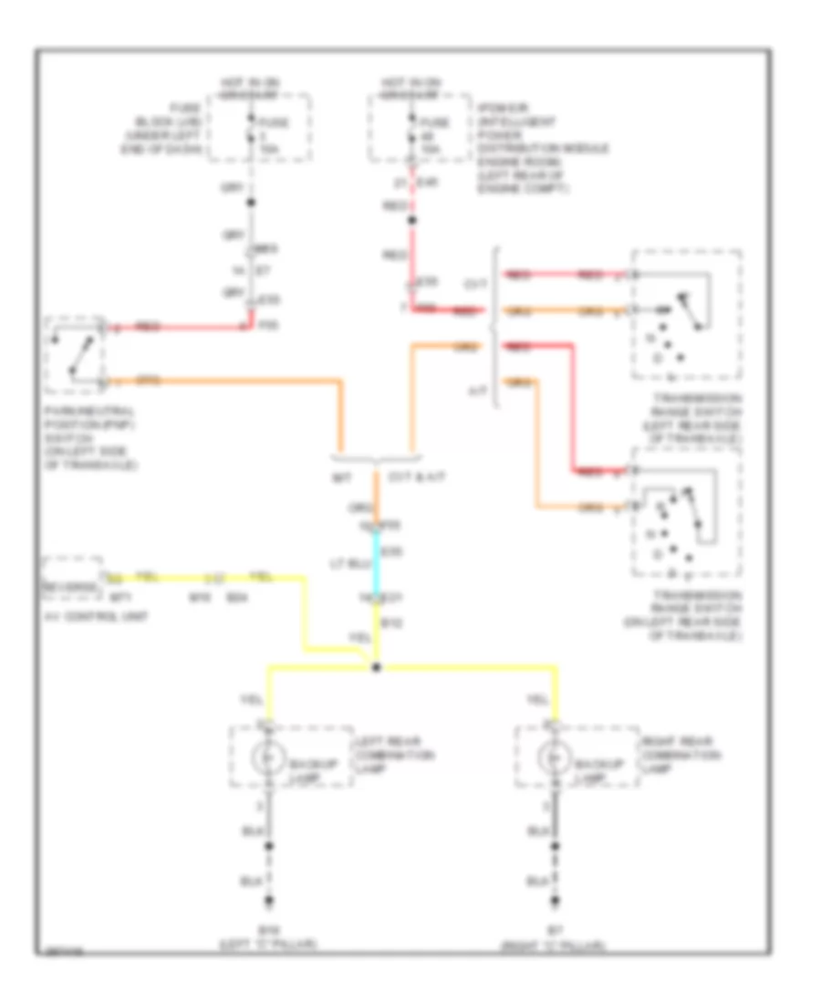
EXTERIOR LIGHTS Backup Lamps Wiring Diagram for Nissan Versa S 2013 List of elements for Backup Lamps Wiring Diagram for Nissan Versa S 2013: 29 (right "c" pillar) A/t Av control unit B12 B19 (left "c" pillar) B24 Backup lamp Cvt Cvt & a/t E21 E45 E55 E7 1a F55 Fuse 10a Fuse block (j/b) (under left end of dash) Hot in on or start Ipdm e/r (intelligent power distribution module engine room) (left rear of engine compt) Left rear combination lamp M/t M16 M69 M71 Park/neutral position (pnp) switch (on left side of transaxle) Red Reverse Right rear combination lamp Transmission range switch (left rear side of transaxle) Transmission range switch (on left rear side of transaxle) Exterior Lamps Wiring Diagram (1 of 2) for Nissan Versa S 2013 List of elements for Exterior Lamps Wiring Diagram (1 of 2) for Nissan Versa S 2013: 56 91a 92a B19 (left "c" pillar) B23 Bat (f/l) Bat (fuse) Bcm (body control module) (behind left end of dash) Can-h Can-l Combination meter Combination switch Computer data lines system Early production Fuse & fusible link box (left rear of engine compt) Fuse 10a Fuse block (j/b) (under left end of dash) Fusible link g 40a Gnd Hazard sw Hazard switch High mounted stop lamp Hot at all times Hot in on or start Input 1 Input 2 Input 3 Input 4 Input 5 Interior lights system J/c e02 (behind left end of dash) Late production Left turn ind Lt flasher o/p M15 M18 M20 M28 M57 (behind left side of dash) M61 (behind side end of dash) M69 M97 M99 Output 1 Output 2 Output 3 Output 4 Output 5 Pnk Red Right turn ind Rt flasher o/p Stop lamp switch (on brake pedal bracket) Tail ind Unified meter control unit (w/ inform- ation display) W/ intelligent key system W/o intelligent key system Exterior Lamps Wiring Diagram (2 of 2) for Nissan Versa S 2013 List of elements for Exterior Lamps Wiring Diagram (2 of 2) for Nissan Versa S 2013: 41 (behind left end of dash) j/c e02 B12 B19 (left "c" pillar) B24 B31 B375 B7 (right "c" pillar) Backup Backup lamps circuit Computer data Cpu E15 (left rear of engine compt) E21 E22 E24 (right rear of engine compt) E27 E28 E29 E30 E45 E46 Fuse 10a Hot at all times Ipdm e/r (intelligent power distribution module engine room) (left rear of engine compt) Left front combination lamp Left license plate lamp Left rear combination lamp Lines system M16 M69 Parking Pnk Red Right front combination lamp Right license plate lamp Right rear combination lamp Side marker Stop Tail Tail lamp relay Turn
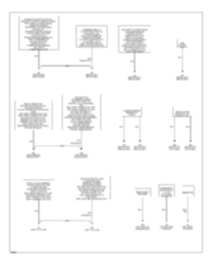
GROUND DISTRIBUTION Ground Distribution Wiring Diagram for Nissan Versa S 2013 List of elements for Ground Distribution Wiring Diagram for Nissan Versa S 2013: 28 (or shield) Abs actuator & electric unit (control unit) Accessory relay 2 a/t shift selector (a/t), fuse block (j/b), data link connector, combination meter, cvt shift selector (cvt), av control unit & right power window & door lock/unlock switch Air bag diagnosis sensor unit shield Air fuel ratio (a/f) sensor 1 shield, electric throttle control actuator shield, ecm, right front combination lamp, left front combination lamp, daytime light relay 1, daytime light relay 2, ipdm e/r (intelligent power distribution module engine room), left front fog lamp, output speed sensor, tcm (transmission control module), secondary speed sensor & primary speed sensor B19 (left "c" pillar) B43 (left front of luggage compt) B7 (right "c" pillar) Condenser & ignition coils 1, 2, 3 & 4 (w/ power transistor) E15 (left rear of engine compt) E24 (right rear of engine compt) E59 (behind left kick panel) E60 (behind left kick panel) E61 (behind left end of dash) Eps control unit F16 (top left side of engine) F5 (left front of engine) Front wiper motor, cooling fan motor (w/o a/c), cooling fan motor (w/ dual connector cooling fan), horn, left front combination lamp, right front combination lamp, cooling fan motor (w/ a/c), brake fluid level switch, washer fluid level switch, right front fog lamp, pre-wiring for front fog lamp & cooling fan relay Generator High mounted stop lamp (w/ rear spoiler), inside key antenna (trunk room) shield, left seat belt buckle switch, left rear combination lamp, occupant classification system control unit, fuel level sensor unit & fuel pump & right seat belt buckle switch Left front outside handle, door mirror remote control switch, combination switch, front air control, console power socket, left door mirror, main power window & door lock/unlock switch, left front door lock, key cylinder switch & right door mirror M57 (behind left end of dash) M61 (behind side end of dash) M79 (behind right end of dash) M84 (behind right side of dash) M85 (behind right end of dash) Push-button ignition switch, inside key antenna (console) shield, right front outside handle, inside key antenna (instrument center) shield, dongle unit, bcm (body control module), nats antenna amplifier, vdc off switch, air bag diagnosis sensor unit, front passenger air bag off indicator, hazard switch , steering angle sensor, map lamp & interior room lamp Rear window defogger
HEADLIGHTS Headlights Wiring Diagram, with DRL for Nissan Versa S 2013 List of elements for Headlights Wiring Diagram, with DRL for Nissan Versa S 2013: 87 (behind left side of dash) m57 (in relay holder above fuse block (j/b)) front fog lamp relay (left rear of engine compt) e15 (w/ information display) unified meter control unit Bat Bat (f/l) Bat (fuse) Body control module (bcm) (behind left end of dash) Brake ind Can-h Can-l Combination meter Combination switch (lighting & turn signal switch) Computer data lines system Cpu Daytime light relay 1 (in relay holder above fuse block (j/b)) Daytime light relay 2 (in relay holder above fuse block (j/b)) Dr sw (as) Dr sw (dr) Dr sw (rl) Dr sw (rr) Dtrl rly E15 (left rear of engine compt) E24 (right rear of engine compt) E25 E26 E42 E44 E45 E46 E7 91a Early production Fr fog relay Front fog lamps Fuse & fusible link box (left rear of engine compt) Fuse 10a Fuse 15a Fuse block (j/b) (under left end of dash) Fusible link box (battery) (on battery (+) terminal) Fusible link e 80a Fusible link g 40a Gnd Gnd (circuit) Gnd (ill) Gnd (pwr) Gnd (sig) Headlamp Headlamp high relay High High beam ind Hot at all times Hot in on or start Ign Input 1 Input 2 Input 3 Input 4 Input 5 Interior lights system Ipdm e/r (intelligent power distribution module engine room) (left rear of engine compt) Late production Left front combination lamp Left front fog lamp Low Low relay M100 M18 M19 M20 M61 (behind side end of dash) M69 Output 1 Output 2 Output 3 Output 4 Output 5 Parking brake switch (base of parking brake lever assembly) Pnk Pre wiring for front fog lamps Prk brk sw sig Red Right front combination lamp Right front fog lamp W/ front fog lamps W/ intelligent key system W/ pre wirning W/o intelligent key system Headlights Wiring Diagram, without DRL for Nissan Versa S 2013 List of elements for Headlights Wiring Diagram, without DRL for Nissan Versa S 2013: 80 (in relay holder above fuse block (j/b)) front fog lamp relay (left rear of engine compt) e15 (on battery (+) terminal) (w/ information display) unified meter control unit Bat Bat (f/l) Bat (fuse) Bcm (body control module (behind left end of dash) Can-h Can-l Combination meter Combination switch (lighting & turn signal switch) Computer data lines system Cpu Dr sw (as) Dr sw (dr) Dr sw (rl) Dr sw (rr) E15 (left rear of engine compt) E24 (right rear of engine compt) E25 E26 E42 E44 E45 E46 E7 91a Early production Fr fog relay Fuse & fusible link box (left rear of engine compt) Fuse 10a Fuse 15a Fuse block (j/b) (under left end of dash) Fusible link box (battery) Fusible link e 80a Fusible link g 40a Gnd Gnd (circuit) Gnd (ill) Gnd (pwr) Gnd (sig) Headlamp high relay Headlamp low relay High High beam ind Hot at all times Hot in on or start Ign Input 1 Input 2 Input 3 Input 4 Input 5 Interior lights system Ipdm e/r (intelligent power distribution module engine room) (left rear of engine compt) Late production Left front combination lamp Left front fog lamp Low M100 M18 M19 M20 M57 (behind left side of dash) M61 (behind side end of dash) M69 Output 1 Output 2 Output 3 Output 4 Output 5 Pnk Pre wiring for front fog lamps Red Right front combination lamp Right front fog lamp W/ front fog lamps W/ intelligent key system W/ pre wirning front fog lamps W/o intelligent key system
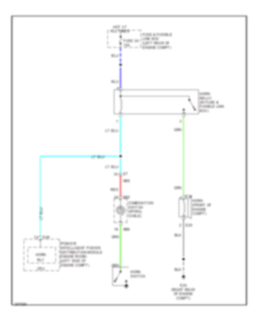
HORN Horn Wiring Diagram for Nissan Versa S 2013 List of elements for Horn Wiring Diagram for Nissan Versa S 2013: 19 Combination switch (spiral cable) Cpu E18 E20 E24 (right rear of engine compt) E46 Fuse & fusible link box (left rear of engine compt) Fuse 24 10a Horn Horn (front of engine compt) Horn relay (in fuse & fusible link box) Horn switch Hot at all times Ipdm e/r (intelligent power distribution module engine room) (left side of engine compt) M30 M69 M88 Red Rly
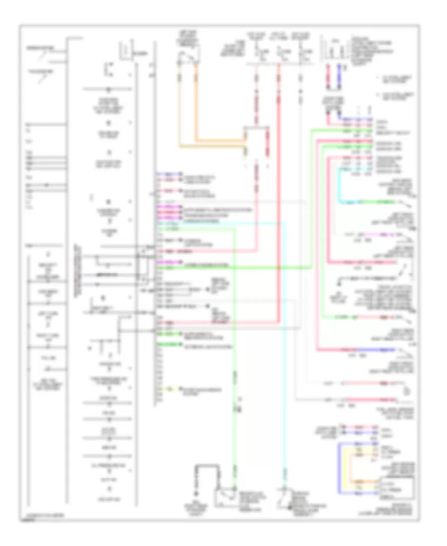
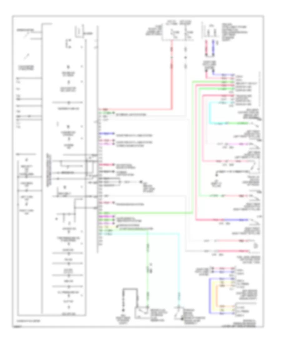
INSTRUMENT CLUSTER Instrument Cluster Wiring Diagram, Early Production for Nissan Versa S 2013 List of elements for Instrument Cluster Wiring Diagram, Early Production for Nissan Versa S 2013: 85 (behind left side of dash) m57 (left end of dash) accessory relay 2 (w/ information display) unified meter control unit 18a A vcci Abs ind Air bag ind B24 B29 B7 (right "c" pillar) Bcm (body control module) (behind left end of dash) Brake fluid level switch (on brake fluid reservoir) Brake ind Buzzer Can-h Can-l Charge ind Combination meter Computer data lines system Cpu Cruise ind (w/ ascd) Door ind Door sw (as) Door sw (dr) Door sw (rr) E16 E24 (right rear of engine compt) E46 Ecm (engine control module) (left rear of engine compt) Engine oil pressure sensor (lower left side of engine) Exterior lights system F11 Fuel level sensor unit & fuel pump (on fuel tank) Fuse 10a Fuse block (j/b) (under left end of dash) Gnd a High beam ind Hot at all times Hot in on or acc Hot in on or start Interior lights system Ipdm e/r (intelligent power distribution module engine room) (left rear of engine compt) Key ind (w/ intelligent key system) Left front door switch (left front "b" pillar) Left rear door switch (left rear "c" pillar) Left turn ind M100 M12 M16 M18 M19 M57 (behind left side of dash) M69 M97 Malfunction ind lamp (mil) Navigation & sound systems O/d off (w/ cvt) Oil press Oil pressure ind Parking brake switch (base of parking brake lever assembly) Pnk Ps ind Push eng start ind (w/ intelligent key system) Red Right front door switch (right front "b" pillar) Right rear door switch (right rear "c" pillar) Right turn ind Seat belt ind Security ind (w/ immobilizer) Security ind out Slip ind Speedometer Starting/charging system Tachometer Tail ind Tire pressure ind (if equipped) Transmissions system Trunk lid switch (w/o intelligent key system) trunk lid lock assembly (w/ intelligent key system) (w/o intelligent key system: center rear of trunk) Trunk/glass hatch sw door sw (rl) Vdc off ind W/ intelligent key system W/o intelligent key system Warning systems Washer ind (canada) Wiper/washer system Instrument Cluster Wiring Diagram, Late Production for Nissan Versa S 2013 List of elements for Instrument Cluster Wiring Diagram, Late Production for Nissan Versa S 2013: 78 (w/ information display) unified meter control unit 18a A vcci Abs ind Air bag ind B24 B29 B7 (right "c" pillar) Bcm (body control module) (behind left end of dash) Brake fluid level switch (on brake fluid reservoir) Brake ind Buzzer Can-h Can-l Charge ind Combination meter Computer data lines system Cpu Cruise ind (w/ ascd) Door ind Door sw (as) Door sw (dr) Door sw (rl) Door sw (rr) E16 E24 (right rear of engine compt) E46 Ecm (engine control module) (left rear of engine compt) Engine oil pressure sensor (lower left side of engine) Exterior lights system F11 Fuel level sensor unit & fuel pump (on fuel tank) Fuse 10a Fuse block (j/b) (under left end of dash) Gnd a Hatch sw High beam ind Hot at all times Hot in on or start Interior lights system Ipdm e/r (intelligent power distribution module engine room) (left rear of engine compt) Left front door switch (left front "b" pillar) Left rear door switch (left rear "c" pillar) Left turn ind M12 M16 M18 M19 M57 (behind left side of dash) M69 Malfunction ind lamp (mil) Navigation & sound systems O/d off (w/ cvt) Oil press Oil pressure ind Parking brake switch (base of parking brake lever assembly) Pnk Ps ind Red Right front door switch (right front "b" pillar) Right rear door switch (right rear "c" pillar) Right turn ind Seat belt ind Security ind (w/ immobilizer) Security ind out Slip ind Speedometer Starting/charging system Tachometer (if equipped) Temperature ind Tire pressure ind (if equipped) Transmissions system Trunk lid switch (center rear of trunk) Trunk/glass Vdc off ind Warning systems Washer ind (canada) Wiper/washer system
INTERIOR LIGHTS Courtesy Lamps Wiring Diagram for Nissan Versa S 2013 List of elements for Courtesy Lamps Wiring Diagram for Nissan Versa S 2013: 49 (if equipped) trunk room lamp (w/o intelligent key system) key switch 91a B24 B29 B7 (right "c" pillar) Bat (f/l) Bat (fuse) Bat saver Body control module (bcm) (behind left end of dash) Can-h Can-l Computer data lines system Door Door sw (as) Door sw (dr) Door sw (rl) Door sw (rr) Fuse & fusible link box (left rear of engine compt) Fuse 10a Fuse block (j/b) (under left end of dash) Fusible link g 40a Gnd Hot at all times Hot in on or start Ign sw Interior room lamp Key sw Left front door switch (left front "b" pillar) Left rear door switch (left rear "c" pillar) Luggage lamp M12 M16 M18 M19 M20 M61 (behind side end of dash) M69 Map lamp (if equipped) Off Pnk Red Right front door switch (right front "b" pillar) Right rear door switch (right rear "c" pillar) Room lamp out Trunk lid switch (center rear of trunk) Trunk/glass hatch sw W/ intelligent key system W/o intelligent key system Instrument Illumination Wiring Diagram for Nissan Versa S 2013 List of elements for Instrument Illumination Wiring Diagram for Nissan Versa S 2013: 77 (w/ infor- mation display) meter control unit 91a m69 Ascd steering switch (if equipped) Audio unit Av control unit (w/ premium audio system) Bat (f/l) Bat (fuse) Body control module (bcm) (behind left end of dash) Can-h Can-l Combination meter Combination switch Computer data lines system Cpu Cvt shift selector (if equipped) Diode (w/ intelligent key system) (behind center of dash) E15 (left rear of engine compt) E45 E46 E7 2a Early production Front air control Fuse & fusible link box (left rear of engine compt) Fuse 10a Fuse block (j/b) (under left end of dash) Fusible link g 40a Gnd Gnd (sig) Hazard switch Hi side eng st sw illu led out Hot at all times Hot in on or start Ig+ Ill+ Ill- Input 1 Input 2 Input 3 Input 4 Input 5 Ipdm e/r (intelligent power distribution module engine room) (left rear of engine compt) J/c m03 (behind center of dash) Late production Low side eng M18 M20 M28 M30 M31 M43 M43 m45 M45 M57 (behind left side of dash) M61 (behind side end of dash) M69 M88 M97 M98 M99 Output 1 Output 2 Output 3 Output 4 Output 5 Pnk Push button ignition switch (w/ intelligent key system) Red Spiral cable (combination switch) St sw illu led Steering wheel audio control switches (except base audio system) Tail lamp relay Tail/l rly Vdc off switch W/ base audio system W/ intelligent key system W/ mid audio system W/o intelligent key system
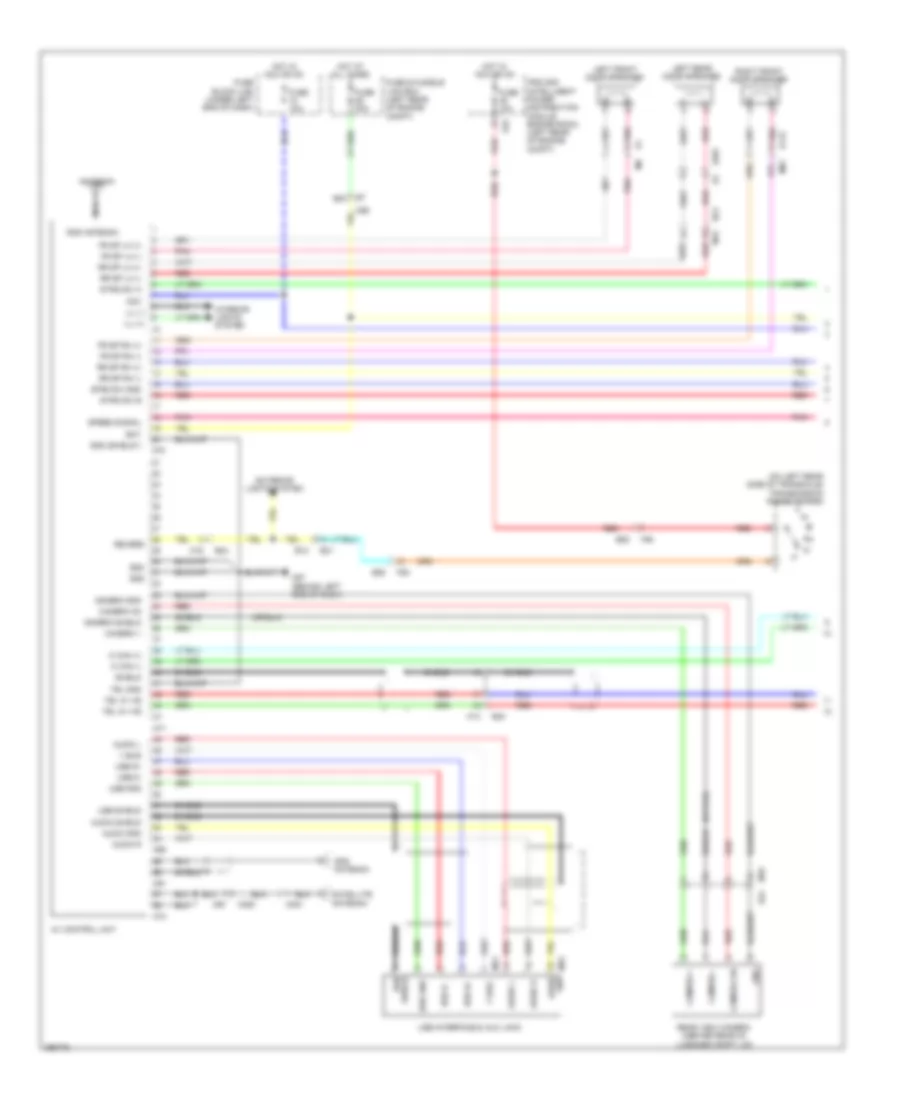
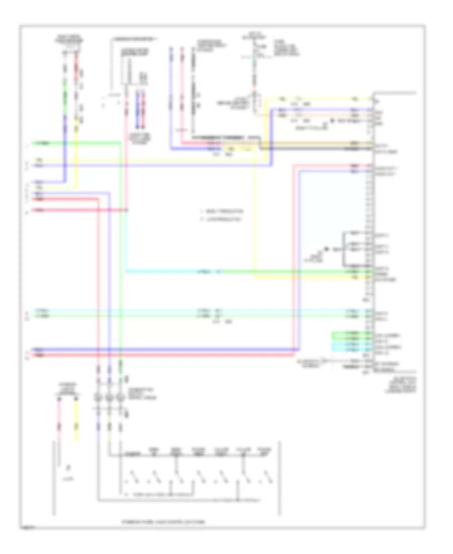
NAVIGATION Navigation Wiring Diagram (1 of 2) for Nissan Versa S 2013 List of elements for Navigation Wiring Diagram (1 of 2) for Nissan Versa S 2013: 92 (on left rear side of transaxle) transmission range switch 95a Acc Antenna Audio Audio gnd Audio l Audio r Audio shield Av control unit B12 B23 B24 B30 Bat Camera + Camera - Camera gnd Camera on Camera shield D115 D201 E21 E45 E55 Eq2 Eq3 Exterior lights system F55 Fr sp lh (+) Fr sp lh (-) Fr sp rh (+) Fr sp rh (-) Fuse & fusible link box (left rear of engine compt) Fuse 10a Fuse 20a Fuse block (j/b) (under left end of dash) Gnd Gnd (shield1) Gps antenna Hot at all times Hot in acc or on Ill (+) Ill (-) Interior lights system Ipdm e/r (intelligent power distribution module engine room) (left rear of engine compt) Left front door speaker Left rear door speaker M can (+) M can (-) M13 M15 M16 M350 M351 M57 (behind left end of dash) M67 M68 M69 M70 M71 M72 M73 M76 gnd M81 M91 Nca Pnk Rear view camera (center rear of luggage compt lid) Red Revers Right front door speaker Rod antenna Rr sp lh (+) Rr sp lh (-) Rr sp rh (+) Rr sp rh (-) Satellite antenna Shield Speed signal Strg sw a Strg sw b Strg sw gnd Tel gnd Tel in +ve Tel in -ve Usb d+ Usb d- Usb gnd Usb interface & aux jack Usb shield V bus Navigation Wiring Diagram (2 of 2) for Nissan Versa S 2013 List of elements for Navigation Wiring Diagram (2 of 2) for Nissan Versa S 2013: 60 Acc Audio out + Audio out - B11 B29 B30 B33 B34 B47 B7 (right "c" pillar) Bt antenna Bt shield Can +2 Can -l2 Can h1 Can jumper 1 Can jumper 2 Can l1 Can-h can-l Combination meter Combination switch (spiral cable) Computer data lines system Cont 2 Cont 4 Cont 5 Cont 6 D301 Early production Fuse 10a Fuse block (j/b) (under left end of dash) Gnd Hot in on or start Ign Illum Interior lights system J/c m01 (behind center of dash) Late production M12 M13 M30 M88 Mic in + Mic in -(gnd) Mic power Microphone (center front of roof) Phone/ end Phone/ send Pnk Red Right rear door speaker Seek down Seek up Shield Source Speed Speed out 8 Steering wheel audio control switches Unified meter control unit Volume down Volume up
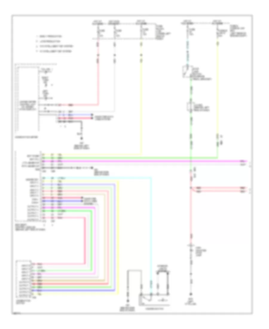
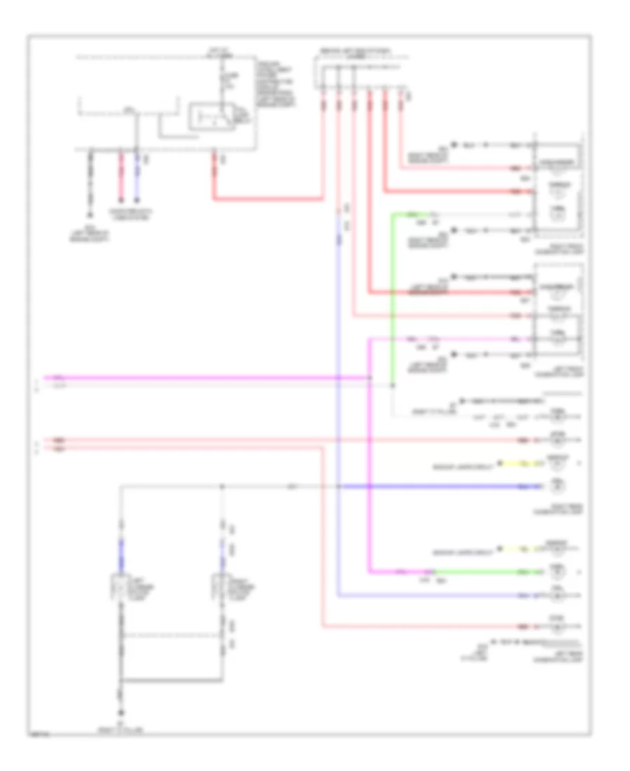
POWER DISTRIBUTION Power Distribution Wiring Diagram (1 of 3) for Nissan Versa S 2013 List of elements for Power Distribution Wiring Diagram (1 of 3) for Nissan Versa S 2013: 54 (left rear of engine compt) ipdm e/r (intelligent power distribution module engine room) A/c comp A/c relay Air conditioning system Battery Cooling fan high relay Cooling fan low relay Cpu E10 E11 E15 (left rear of engine compt) E42 E44 E45 E46 Exterior lights system F/wip hi rly F/wip rly F39 F40 From ignition relay 1 (diagram 2 of 3) Front wiper high relay Front wiper relay Fuse 10a Fuse 15a Fuse 30a Fusible link a 120a Fusible link b 60a Fusible link box (battery) (on battery (+) terminal) Fusible link c 80a Fusible link d 100a Fusible link e 80a Gnd (pwr) Gnd (sig) H/lp hi H/lp lo Headlamp high relay Headlamp low relay Headlights system Horn rly Horns system Interior lights system M78 Nca Pnk Red Starting/ charging system Tail lamp relay Tail/l rly To fuse & fusible link box (diagram 3 of 3) To fuse block (j/b) (diagram 2 of 3) To ipdm e/r (intelligent power distribution module engine room) (diagram 2 of 3) Wiper/washer system Wpr autostop Power Distribution Wiring Diagram (2 of 3) for Nissan Versa S 2013 List of elements for Power Distribution Wiring Diagram (2 of 3) for Nissan Versa S 2013: 69 (diagram 1 of 3) (diagram 3 of 3) (left rear of engine compt) ipdm e/r (intelligent power distribution module engine room) 47a e7 93a Acc Accessory relay 1 Air conditioning system Anti-lock brakes system Anti-theft system Anti-theft, defogger, interior lights, warning, body computer & shift interlock systems Blower relay Body computer & wiper/washer systems Can h Can l Computer data lines system Console power socket Cpu Defogger system Door locks, body computer, anti-lock brakes, transmissions, shift interlock, anti-theft, wiper/washer, warning, engine controls, headlights, exterior lights, instrument cluster, interior lights & electronic power steering systems Door locks, body computer, headlights, interior lights, anti-theft, exterior lights & warning systems E42 E43 E44 E45 E46 E47 Ecm relay Engine controls & cooling fans systems Engine controls & transmissions systems Engine controls system F42 F43 From accessory relay 2 k From fuse & fusible link box (diagram 3 of 3) From fusible link box (battery) (diagram 1 of 3) From ignition relay 2 (diagram 3 of 3) Fuel pump relay Fuse 10a Fuse 15a Fuse 20a Fuse block (j/b) (under left end of dash) Ig1 Ig2 Ignition relay 1 Ignition switch (w/o intelli- gent key system) M57 (behind left side of dash) M69 M79 (behind right end of dash) Mirrors system Off Pnk Push strt sw Red Start Start mtr Starter relay Starting/ charging system Throttle control motor relay To front wiper relay (diagram 1 of 3) To front wiper relay d To fuse 14 (diagram 3 of 3) To fuse block (j/b) (diagram 3 of 3) To fuse block (j/b) (diagram 3 of 3) from bcm (diagram 3 of 3) To push button ignition switch (diagram 3 of 3) Transmissions, engine controls, defogger, electronic power steering & sound systems Transmissions, exterior lights, engine controls & starting/ charging systems W/ intelligent key system W/o intelligent key system Power Distribution Wiring Diagram (3 of 3) for Nissan Versa S 2013 List of elements for Power Distribution Wiring Diagram (3 of 3) for Nissan Versa S 2013: 56 (behind left end of dash) bcm (body control module) (diagram 2 of 3) Acc rly output Acc/ on Accessory relay 2 (left end of dash) Anti-lock brakes system Anti-theft system Blwr mtr rly output Body computer, anti-lock brakes, transmissions, engine controls & exterior lights systems Cooling fans & air conditioning systems Door locks, body computer, warning, defogger, power windows, headlights, interior lights, exterior lights, shift interlock, wiper/washer, anti-theft & trunk, tailgate, fuel doors systems E7 10a Electronic power steering system Eng strt sw From blower relay h From fuse & fusible link box (diagram 2 of 3) From fusible link box (battery) n (diagram 1 of 3) From ignition switch (diagram 2 of 3) From ipdm e/r (intelligent power distribution module engine room) (diagram 2 of 3) Fuse & fusible link box (left rear of engine compt) Fuse 10a Fuse 10a (if equipped) Fuse 15a (if equipped) Fuse 20a Fuse block (j/b) (under left end of dash) Fusible link f 40a Fusible link g 40a Fusible link h 40a Fusible link i 40a Fusible link j 60a Fusible link m 40a Headlights system Ign rly output 2 Ignition relay 2 Ill Instrument cluster, navigation & body computer systems Interior lights system J/c m05 (behind center of dash) M57 (behind left side of dash) M61 (behind side end of dash) M69 M98 Navigation & sound systems Pnk Push button ignition switch (w/ intelligent key system) Push switch Pwr position led Red Starting/ charging & horns systems To fuse 2 (diagram 2 of 3) To fuse block (j/b) (diagram 2 of 3) To fuse block (j/b) m To ignition switch (diagram 2 of 3) Transmissions system W/ intelligent key system W/o intelligent key system
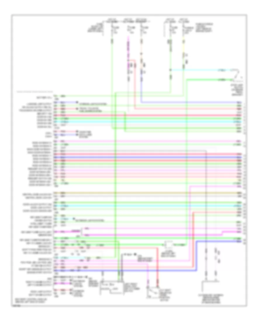
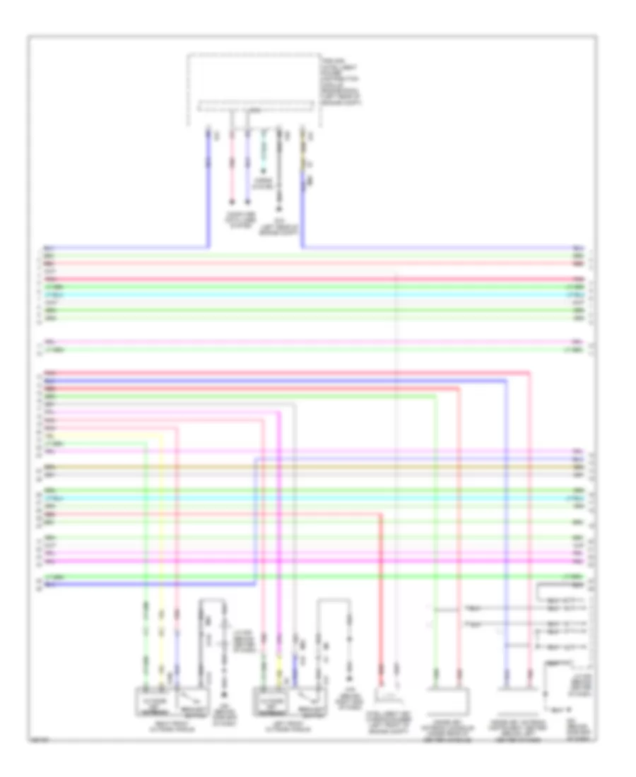
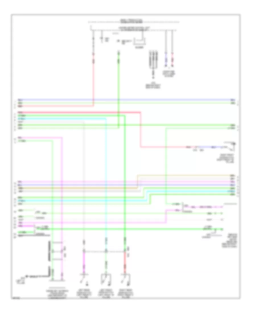
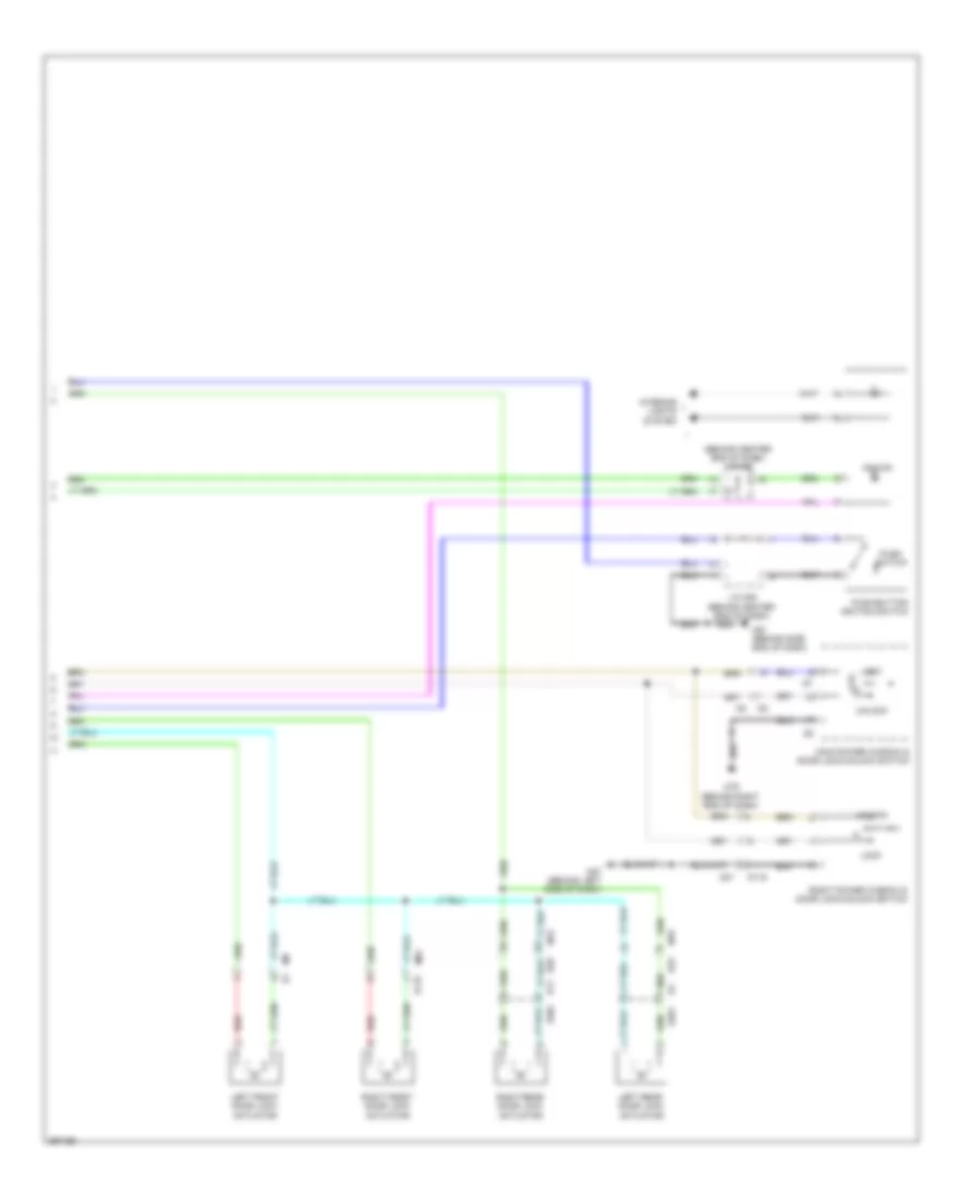
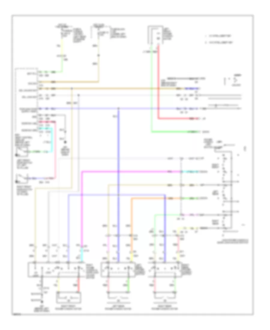
POWER DOOR LOCKS Power Door Locks Wiring Diagram, with Intelligent Key Unit (1 of 4) for Nissan Versa S 2013 List of elements for Power Door Locks Wiring Diagram, with Intelligent Key Unit (1 of 4) for Nissan Versa S 2013: 90 (or red) 1o4 37a 38a red 39a e7 91a 92a 93a At device output B29 Back door antenna + Back door antenna - Batt saver output Battery (f/l) Bcm (body control module) (behind left end of dash) Brake sw 1 Brake sw 2 Can-h Can-l Canada Central door lock sw Central door unlock sw Computer data lines system Cvt shift selector (park position switch Door antenna (as) + Door antenna (as) - Door antenna (dr) + Door antenna (dr) - Door lock output Door sw (as) Door sw (dr) Door sw (rl) Door sw (rr) Door unlock common (dr) Door unlock output (as) Dr unlock output (rr, rl) Engine start switch Exterior lights system Fuse & fusible link box (left rear of engine compt) Fuse 10a Fuse block j/b (under left end of dash) Fusible link g 40a Gnd Hazard switch Hot at all times Hot in on or start Intelligent tuner Interior lights system J/c e02 (behind left end of dash) Key cylinder lock sw Key cylinder unlock sw Keyless tuner auto light Keyless tuner power sply Keyless tuner rssi Keyless tuner sig Left flasher output Left front door lock key cylinder switch Lock Luggage lamp output M100 M12 M61 (behind side end of dash) M69 M79 (behind right end of dash) M97 M98 M99 Outside key antenna (rear bumper) (behind center of rear bumper) Pnk Pow posi led (loc posi led) Red Request switch (as) Request switch (dr) Right flasher output Room antenna 1+ Room antenna 1- Room antenna 2+ Room antenna 2- Room antenna 3+ Room antenna 3- Room lamp output Security ind Sensor gnd Shift p posi park posi sw Smart keyless buzz output Stop lamp switch (on brake pedal bracket) Trunk, tailgate, fuel doors system Trunk/back dr open output Unlock Usa Power Door Locks Wiring Diagram, with Intelligent Key Unit (2 of 4) for Nissan Versa S 2013 List of elements for Power Door Locks Wiring Diagram, with Intelligent Key Unit (2 of 4) for Nissan Versa S 2013: 29 47a Computer data lines system Cpu D106 D113 D116 D16 D17 E15 (left rear of engine compt) E44 E46 E47 Horns system Inside key antenna (console) (under rear of center console) Inside key antenna (instrument center) (behind left center of dash) Intelligent key warning buzzer (left front of engine compt) Ipdm e/r (intelligent power distribution module engine room) (left rear of engine compt) J/c m05 (behind center of dash) Left front outside handle M61 (behind side end of dash) M69 M79 (behind right end of dash) M92 M93 Outside key antenna Pnk Red Request switch Right front outside handle Power Door Locks Wiring Diagram, with Intelligent Key Unit (3 of 4) for Nissan Versa S 2013 List of elements for Power Door Locks Wiring Diagram, with Intelligent Key Unit (3 of 4) for Nissan Versa S 2013: 23 (early production) combination meter B19 (left "c" pillar) B24 B29 Buzzer Canada Computer data lines system Inside key antenna (trunk room) (center front of luggage compt) Key ind Left front door switch (left front "b" pillar) Left rear door switch (left rear "c" pillar) M12 M16 M79 (behind right end of dash) Pnk Red Remote keyless entry receiver (behind right side of dash) Right front door switch (right front "b" pillar) Right rear door switch (right rear "c" pillar) Security ind Shield Unified meter control unit (w/ information display) Usa Power Door Locks Wiring Diagram, with Intelligent Key Unit (4 of 4) for Nissan Versa S 2013 List of elements for Power Door Locks Wiring Diagram, with Intelligent Key Unit (4 of 4) for Nissan Versa S 2013: 28 (behind center end of dash) j/c m05 Acc/on B11 B23 B29 Cpu D115 D201 D301 Interior lights system J/c m05 (behind center end of dash) Left front door lock actuator Left rear door lock actuator Lock M12 M15 M57 (behind left side of dash) M61 (behind side end of dash) M79 (behind right end of dash) M81 Main power window & door lock/unlock switch Push switch Push-button ignition switch Red Right front door lock actuator Right power window & door lock/unlock switch Right rear door lock actuator Unlock Power Door Locks Wiring Diagram, without Intelligent Key Unit for Nissan Versa S 2013 List of elements for Power Door Locks Wiring Diagram, without Intelligent Key Unit for Nissan Versa S 2013: 88 Acc sw Audio/dongle B11 B23 B24 B29 Bat (f/l) Bat (fuse) Batt saver Bcm (body control module) (behind left end of dash) Can- h Can- l Can-h Can-l security ind output Cdl lock sw Cdl unlock sw Combination meter Computer data lines system Cpu D115 D201 D301 Dongle unit (behind left center of dash) Door sw (as) Door sw (dr) Door sw (rl) Door sw (rr) Dr lk output Dr unlk out (all) Dr unlk out (dr) Dtrl E46 E7 91a Early production Exterior lights system Fuse & fusible link box (left rear of engine compt) Fuse 10a Fuse block (j/b) (under left end of dash) Fusible link g 40a Gnd H/lp hi H/lp lo Headlights system Horn rly Horns system Hot at all times Hot in on or acc Interior lights system Ipdm e/r (intelligent power distribution module engine room) (left rear of engine compt) Key cyl lk sw Key cyl unlk sw Key sw Key switch Keyless & auto light sens gnd Late production Left front door lock actuator Left front door lock key cylinder switch Left front door switch (left front "b" pillar) Left rear door lock actuator Left rear door switch (left rear "c" pillar) Lock Lt flasher out Luggage lamp out M12 M15 M16 M18 M19 M20 M57 (behind left side of dash) M61 (behind side end of dash) M69 M79 (behind right end of dash) M81 Main power window & door lock/ unlock switch Pnk Red Remote keyless entry receiver (behind right side of dash) Right front door lock actuator Right front door switch (right front "b" pillar) Right power window & door lock/ unlock switch Right rear door lock actuator Right rear door switch (right rear "c" pillar) Room lamp output Rt flasher out Security ind Un- lock Unlock
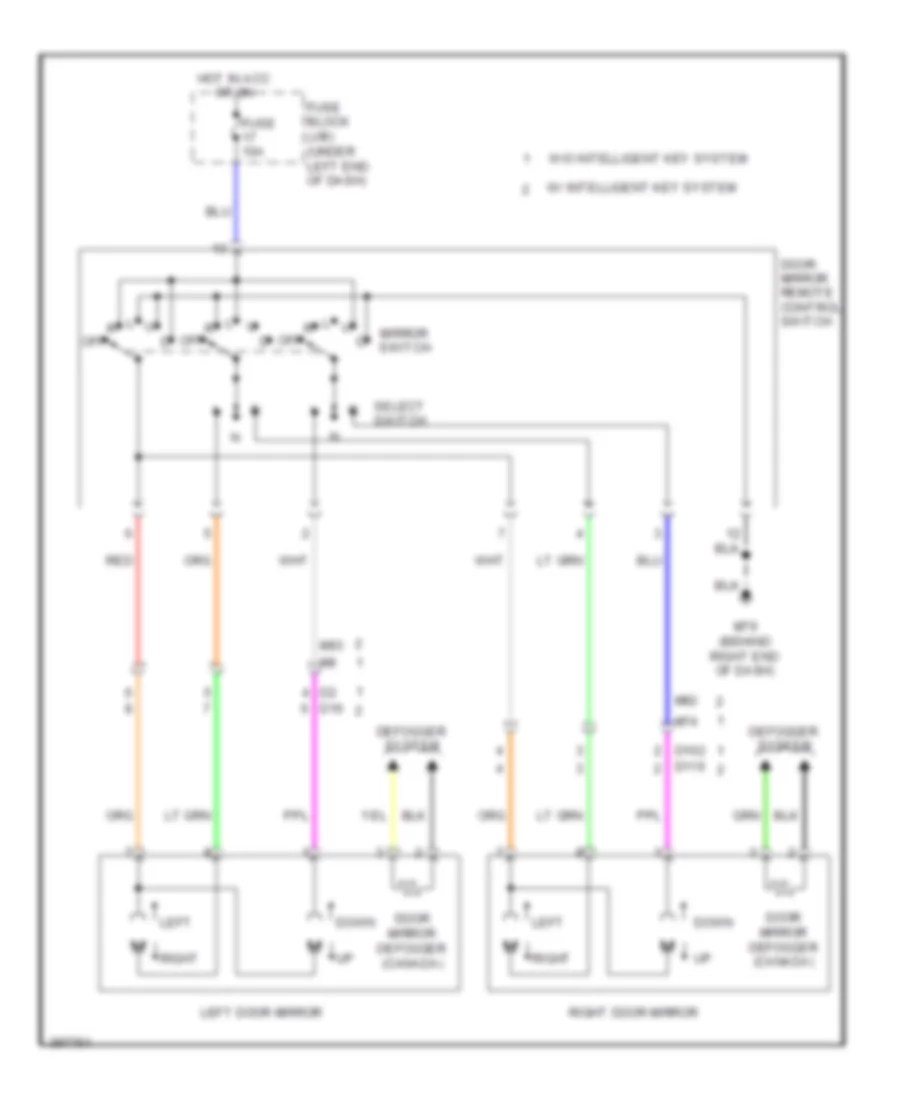
POWER MIRRORS Power Mirrors Wiring Diagram for Nissan Versa S 2013 List of elements for Power Mirrors Wiring Diagram for Nissan Versa S 2013: 24 D102 D116 D16 Defogger system Door mirror defogger (canada) Door mirror remote control switch Down Fuse 10a Fuse block (j/b) (under left end of dash) Hot in acc or on Left Left door mirror M74 M79 (behind right end of dash) M92 M93 Mirror switch R off Red Right Right door mirror Select switch W/ intelligent key system W/o intelligent key system
POWER WINDOWS Power Windows Wiring Diagram for Nissan Versa S 2013 List of elements for Power Windows Wiring Diagram for Nissan Versa S 2013: 61 91a Acc sw B11 B23 B24 m16 B29 Bat (f/l) Bcm (body control module) (behind left end of dash) Cdl lock sw Cdl unlock sw Cpu D1 m9 D115 D2 m8 D201 D301 Door sw (as) Door sw (dr) Down Fuse & fusible link box (left rear of engine compt) Fuse 18 10a Fuse block (j/b) (under left end of dash) Fusible link g 40a Gnd Hot at all times Hot in on or acc Ign Left front door switch (at left "b" pillar) Left front power window motor Left rear Left rear power window motor Left rear power window switch Lock M100 M12 M15 M18 M19 M20 M57 (behind left side of dash) M61 (behind side of dash) M69 M79 (behind right end of dash) M81 M9 d1 M97 M99 Main power window & door lock/unlock switch Pnk Power window lock switch Red Right front Right front door switch (at right "b" pillar) Right front power window motor Right power window & door lock/ unlock switch Right rear Right rear power window motor Right rear power window switch Unlock W/ intelligent key W/o intelligent key
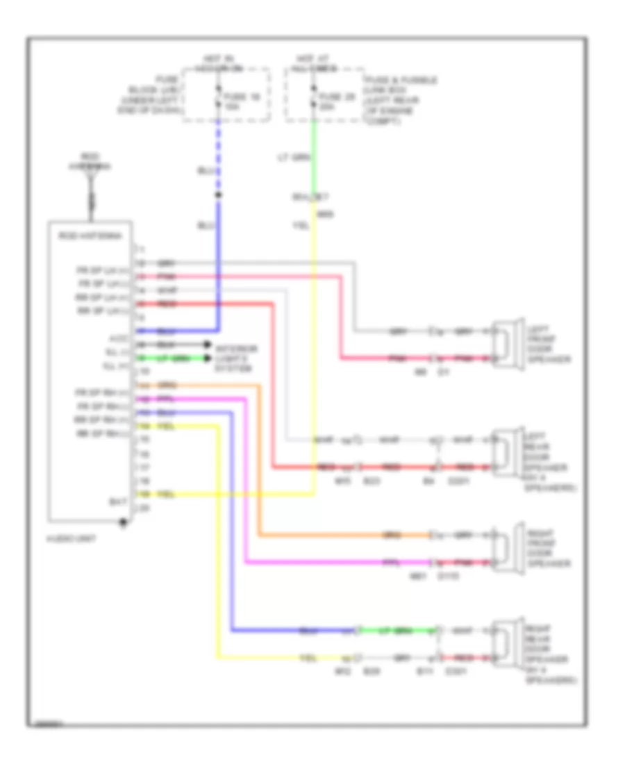
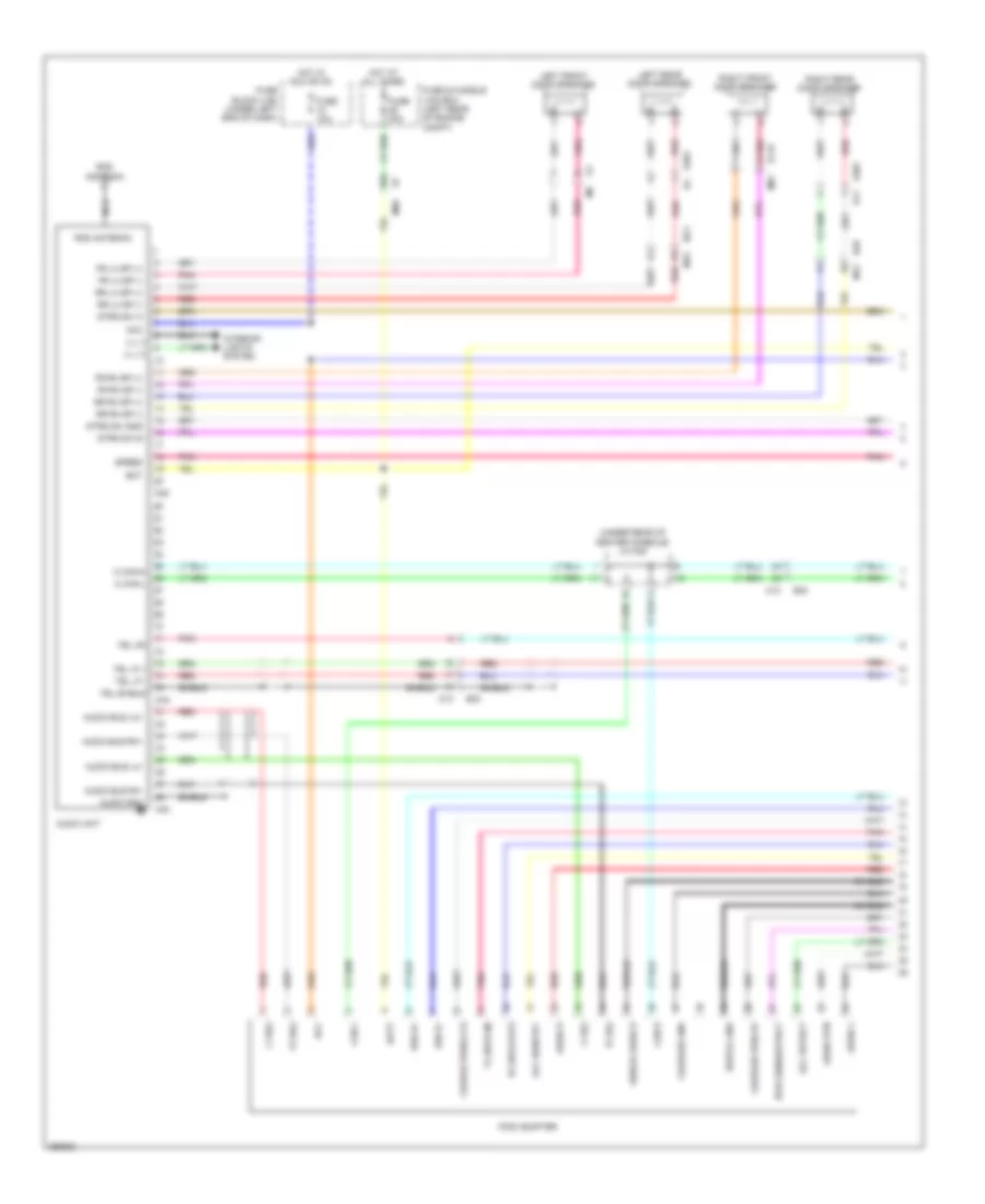
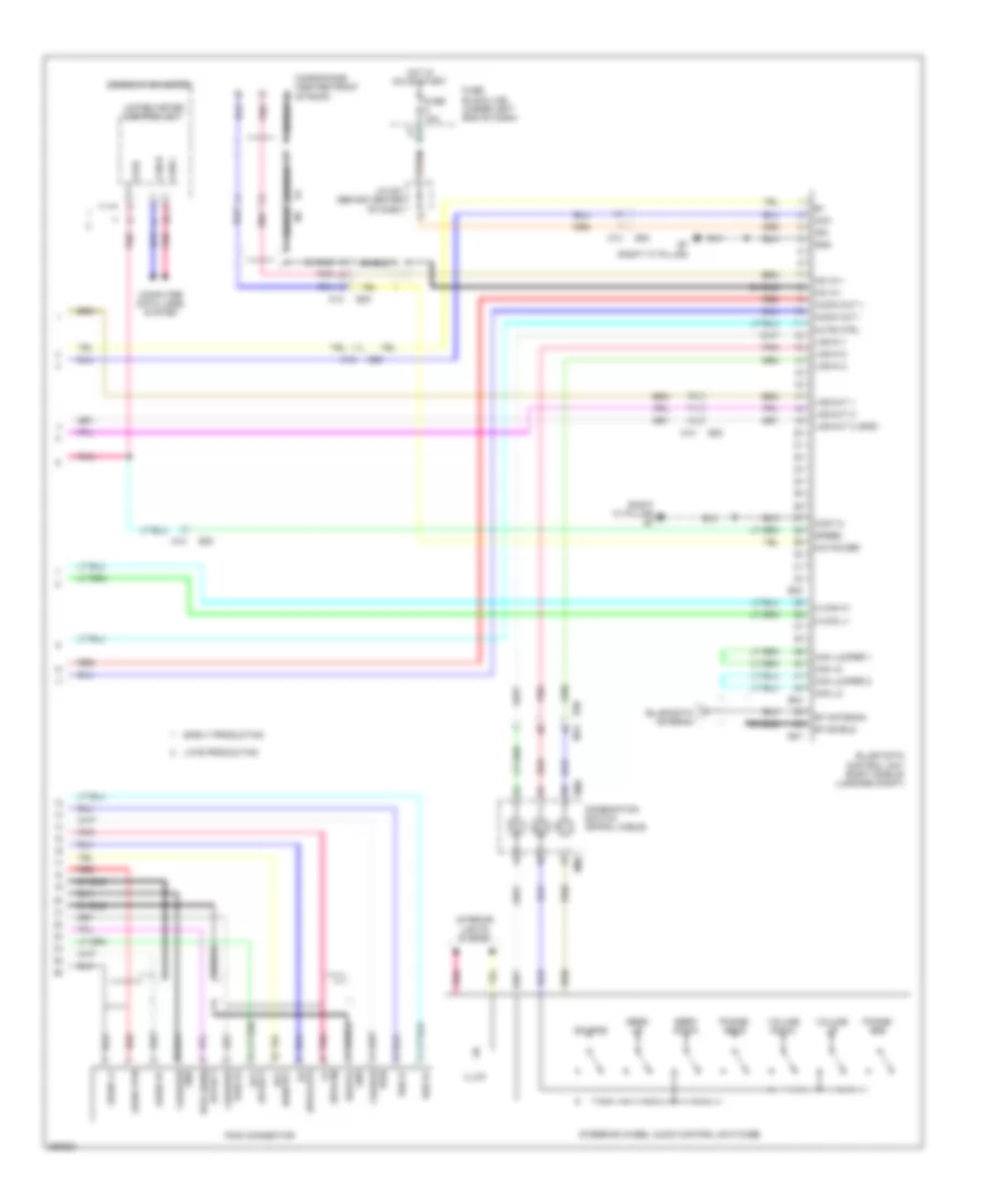
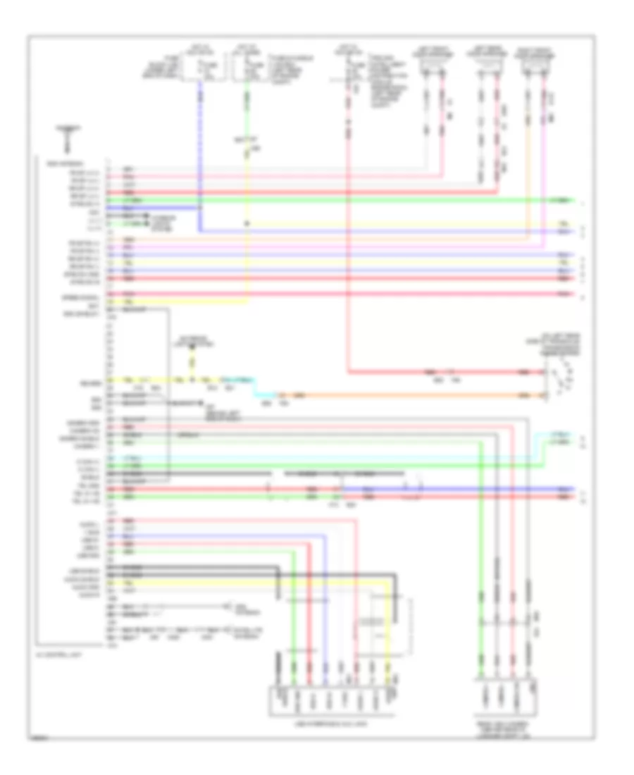
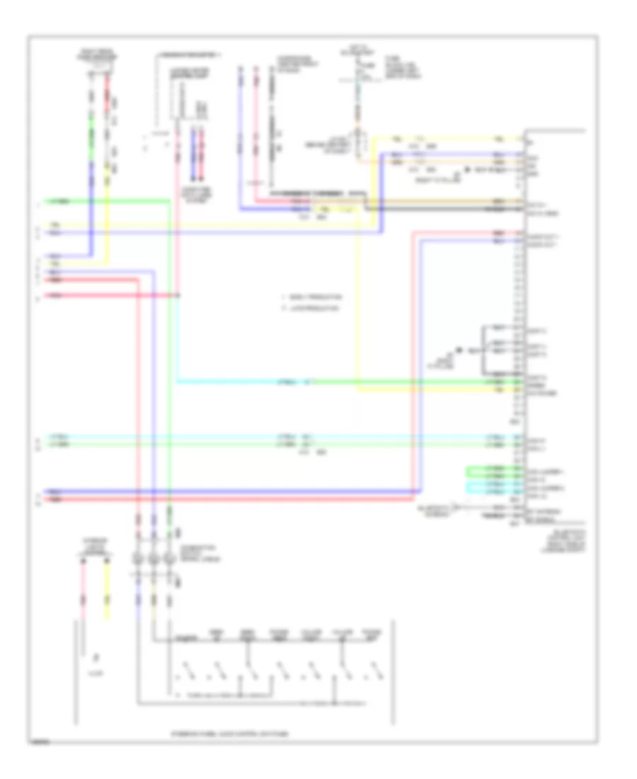
RADIO Base Radio Wiring Diagram for Nissan Versa S 2013 List of elements for Base Radio Wiring Diagram for Nissan Versa S 2013: 39 Acc Audio unit B11 B23 B29 Bat D115 D201 D301 E7 95a Fr sp lh (+) Fr sp lh (-) Fr sp rh (+) Fr sp rh (-) Fuse & fusible link box (left rear of engine compt) Fuse 18 10a Fuse 29 20a Fuse block (j/b) (under left end of dash) Hot at all times Hot in acc or on Ill (+) Ill (-) Interior lights system Left front door speaker Left rear door speaker (w/ 4 speakers) M12 M15 M69 M81 Nca Pnk Red Right front door speaker Right rear door speaker (w/ 4 speakers) Rod antenna Rr sp lh (+) Rr sp lh (-) Rr sp rh (+) Rr sp rh (-) Mid-Line Radio Wiring Diagram (1 of 2) for Nissan Versa S 2013 List of elements for Mid-Line Radio Wiring Diagram (1 of 2) for Nissan Versa S 2013: 84 (under rear of center console) j/c m02 95a Acc Acc detect Acc identify Audio bus lh+ Audio bus lh- Audio bus rh+ Audio bus rh- Audio gnd Audio l Audio r Audio rtn Audio unit B11 B23 B29 B30 Bat Batt Can h Can l Charge pwr(12 v) Charger gnd Charger pwr 5v D115 D201 b4 D301 Digital gnd Fr lh sp (+) Fr lh sp (-) Fr rh sp (+) Fr rh sp (-) Fuse & fusible link box (left rear of engine compt) Fuse 10a Fuse 20a Fuse block (j/b) (under left end of dash) Hot at all times Hot in acc or on Ill (+) Ill (-) Interior lights system Ipod adapter Ipod sens/detect L ch(+) L ch(-) Left front door speaker Left rear door speaker M can-h M can-l M12 M13 M15 M40 M44 M45 M69 M81 Nca Pnk R ch(+) R ch(-) Red Right front door speaker Right rear door speaker Rod antenna Rr lh sp (+) Rr lh sp (-) Rr rh sp (+) Rr rh sp (-) Rx (ipod-out) Shield Shield audio r Speed Strg sw a Strg sw b Strg sw gnd Tel i/f + Tel i/f - Tel on Tel shield Tx (ipod-in) Usd d+ Usd d- Mid-Line Radio Wiring Diagram (2 of 2) for Nissan Versa S 2013 List of elements for Mid-Line Radio Wiring Diagram (2 of 2) for Nissan Versa S 2013: 79 (ipod-in) (ipod-out) (right "c" pillar) b7 8 p/r Acc Audio l+ Audio out + Audio out - Audio r+ Audio rtn B29 B30 B33 B34 B47 B7 (right "c" pillar) Bt-antenna Bt-shield Can +2 Can jumper 1 Can jumper 2 Can l2 Can-h Can-l Charge Charger Combination meter Combination switch (spiral cable) Computer data lines system Cont 6 Detect Digital Early production Fuse 10a Fuse block (j/b) (under left end of dash) Gnd Hot in on or start Identify Ign Illum Interior lights system Ipod connector Ipod sens/ detect J/c m01 (behind center of dash) Lad-in 1 Lad-in 2 Lad-in 3 Lad-out 1 Lad-out 2 Lad-out 3 (gnd) Late production M can h1 M can l1 M12 M13 M30 M88 Mic in + Mic in - Mic power Microphone (center front of roof) Mute ctrl Phone/ end Phone/ send Pnk Pwr Pwr 5v Red Seek down Seek up Shield Source Speed Steering wheel audio control switches Unified meter control unit Usd d+ Usd d- Volume down Volume up Premium Radio Wiring Diagram (1 of 2) for Nissan Versa S 2013 List of elements for Premium Radio Wiring Diagram (1 of 2) for Nissan Versa S 2013: 92 (on left rear side of transaxle) transmission range switch 95a Acc Antenna Audio Audio gnd Audio l Audio r Audio shield Av control unit B12 B23 B24 B30 Bat Camera + Camera - Camera gnd Camera on Camera shield D115 D201 E21 E45 E55 Eq2 Eq3 Exterior lights system F55 Fr sp lh (+) Fr sp lh (-) Fr sp rh (+) Fr sp rh (-) Fuse & fusible link box (left rear of engine compt) Fuse 10a Fuse 20a Fuse block (j/b) (under left end of dash) Gnd Gnd (shield1) Gps antenna Hot at all times Hot in acc or on Ill (+) Ill (-) Interior lights system Ipdm e/r (intelligent power distribution module engine room) (left rear of engine compt) Left front door speaker Left rear door speaker M can (+) M can (-) M13 M15 M16 M350 M351 M57 (behind left end of dash) M67 M68 M69 M70 M71 M72 M73 M76 gnd M81 M91 Nca Pnk Rear view camera (center rear of luggage compt lid) Red Revers Right front door speaker Rod antenna Rr sp lh (+) Rr sp lh (-) Rr sp rh (+) Rr sp rh (-) Satellite antenna Shield Speed signal Strg sw a Strg sw b Strg sw gnd Tel gnd Tel in +ve Tel in -ve Usb d+ Usb d- Usb gnd Usb interface & aux jack Usb shield V bus Premium Radio Wiring Diagram (2 of 2) for Nissan Versa S 2013 List of elements for Premium Radio Wiring Diagram (2 of 2) for Nissan Versa S 2013: 60 Acc Audio out + Audio out - B11 B29 B30 B33 B34 B47 B7 (right "c" pillar) Bt antenna Bt shield Can +2 Can -l2 Can h1 Can jumper 1 Can jumper 2 Can l1 Can-h can-l Combination meter Combination switch (spiral cable) Computer data lines system Cont 2 Cont 4 Cont 5 Cont 6 D301 Early production Fuse 10a Fuse block (j/b) (under left end of dash) Gnd Hot in on or start Ign Illum Interior lights system J/c m01 (behind center of dash) Late production M12 M13 M30 M88 Mic in + Mic in -(gnd) Mic power Microphone (center front of roof) Phone/ end Phone/ send Pnk Red Right rear door speaker Seek down Seek up Shield Source Speed Speed out 8 Steering wheel audio control switches Unified meter control unit Volume down Volume up
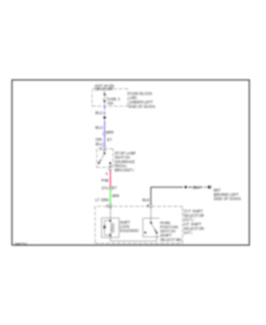
SHIFT INTERLOCK Shift Interlock Wiring Diagram for Nissan Versa S 2013 List of elements for Shift Interlock Wiring Diagram for Nissan Versa S 2013: 12 28a Cvt shift selector (cvt) a/t shift selector (a/t) E7 27a Fuse 5 10a Fuse block (j/b) (under left end of dash) Hot in on or start M57 (behind left side of dash) M69 Park position switch (shift selector) Pnk Shift lock solenoid Stop lamp switch (on brake pedal bracket)
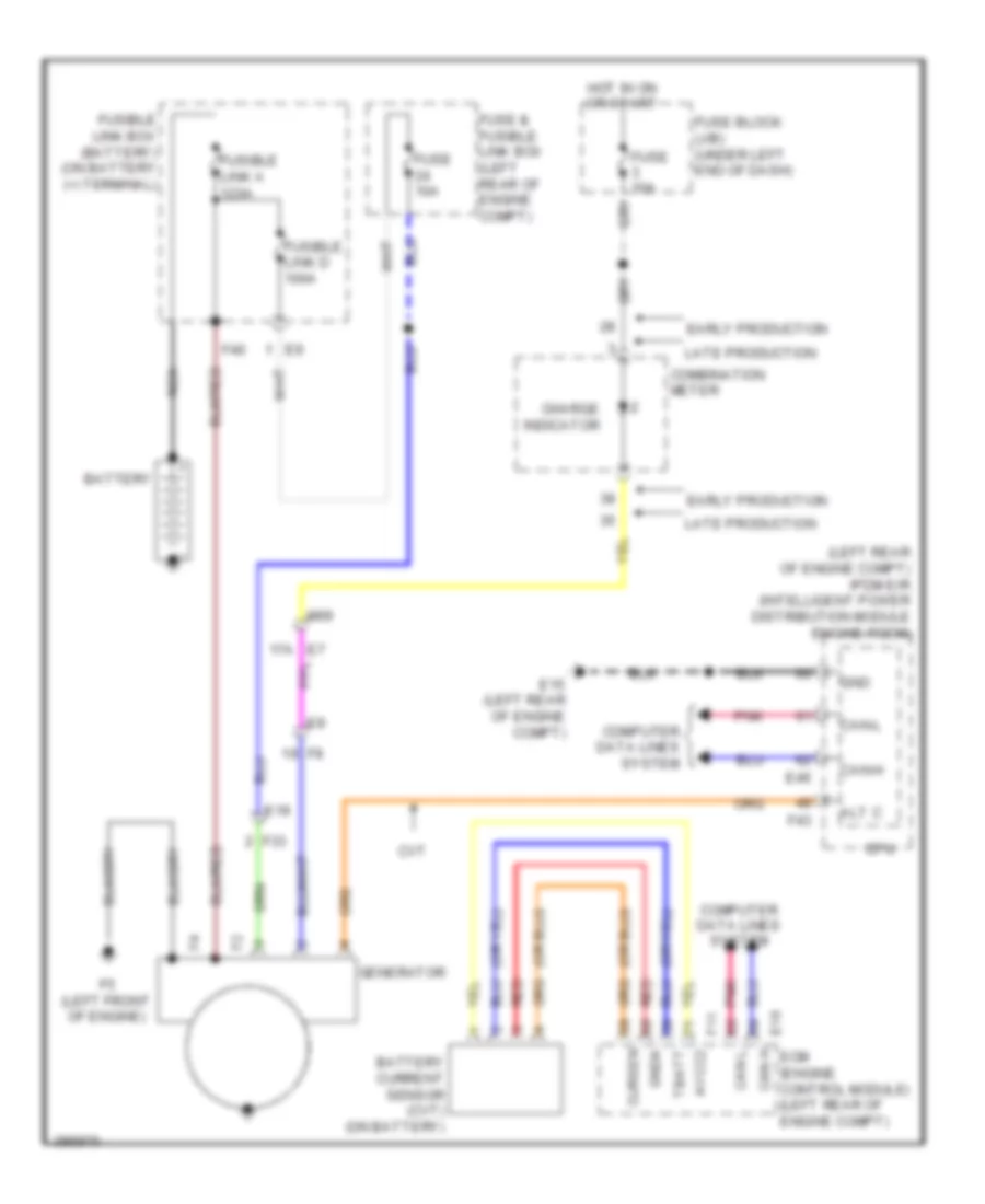
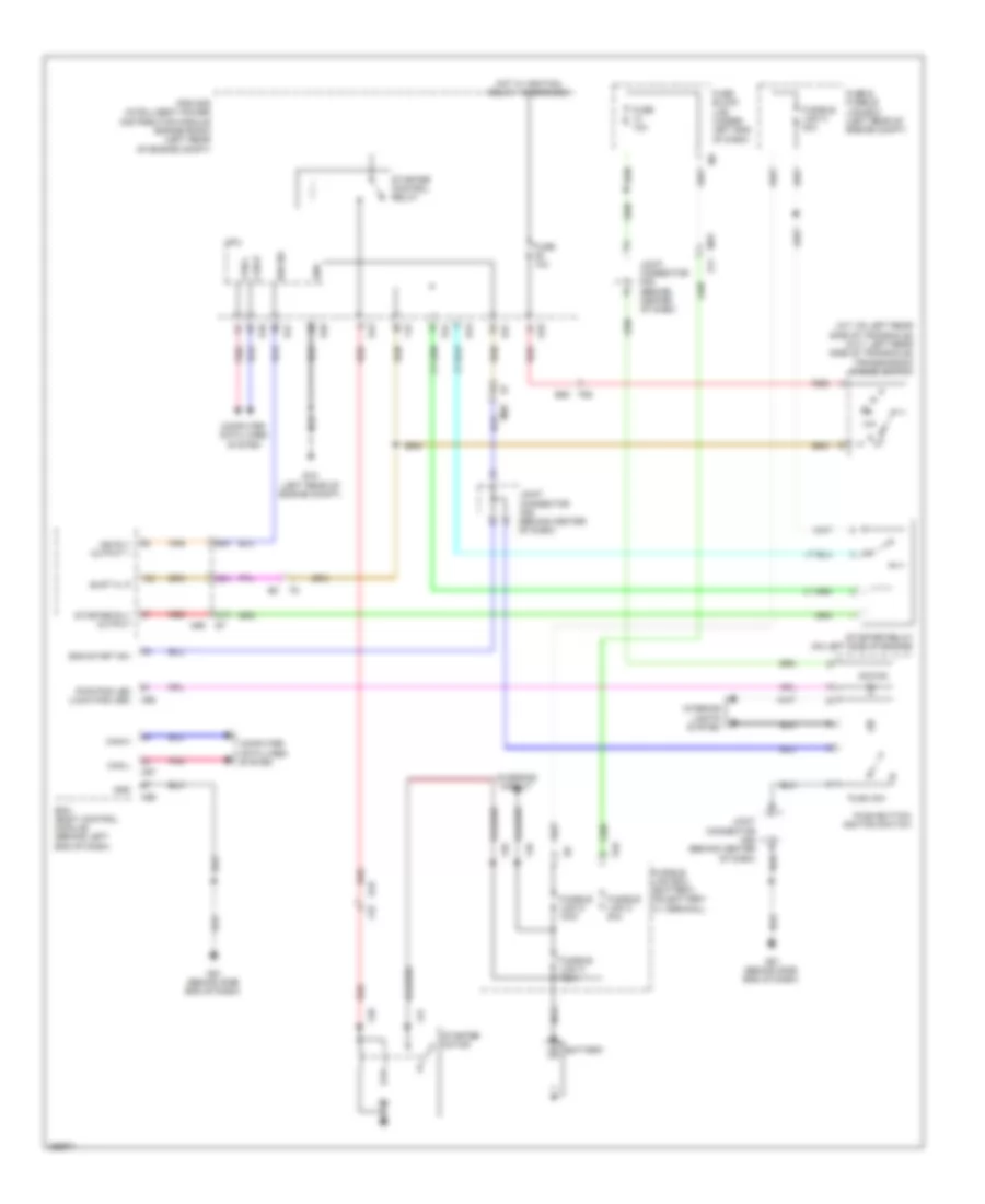
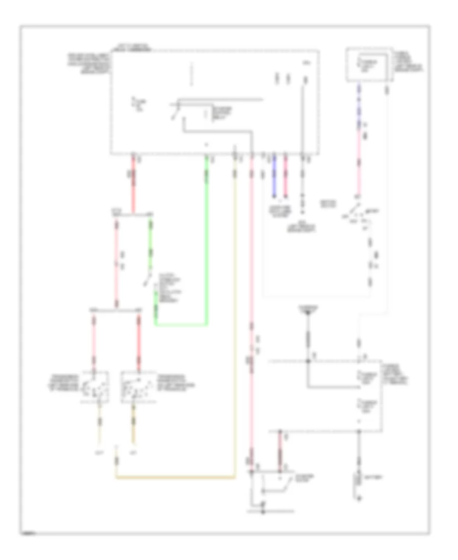
STARTING/CHARGING Charging Wiring Diagram for Nissan Versa S 2013 List of elements for Charging Wiring Diagram for Nissan Versa S 2013: 43 (left rear of engine compt) ipdm e/r (intelligent power distribution module engine room) Alt c Avcc2 Battery Battery current sensor (cvt) (on battery) Can h Can l Can-h Can-l Charge indicator Combination meter Computer data lines system Cpu Cursen Cvt E15 (left rear of engine compt) E16 E19 E46 E7 17a Early production Ecm (engine control module) (left rear of engine compt) F11 F33 F40 F43 F5 (left front of engine) Fuse & fusible link box (left rear of engine compt) Fuse 10a Fuse block (j/b) (under left end of dash) Fusible link a 120a Fusible link box (battery) (on battery (+) terminal) Fusible link d 100a Generator Gnd Gnda Hot in on or start Late production M69 Nca Pnk Red Tbatt Starting Wiring Diagram, with Intelligent Key for Nissan Versa S 2013 List of elements for Starting Wiring Diagram, with Intelligent Key for Nissan Versa S 2013: 63 (a/t: on left rear side of transaxle) (cvt: left rear side of transaxle) transmission range switch 32a 41a 47a 98a Acc/on Battery Bcm (body control module) (behind left end of dash) Can-h Can-l Charging circuit Computer data lines system Cpu E10 E11 E15 (left rear of engine compt) E19 E43 E44 E45 E46 E47 E55 Eng start sw F27 F28 F33 F39 F40 F42 F55 Fuse & fusible link box (left rear of engine compt) Fuse 10a Fuse block (j/b) (under left end of dash) Fusible link a 120a Fusible link box (battery) (on battery (+) terminal) Fusible link c 80a Fusible link d 100a Fusible link h 40a Gnd Hot w/ ignition relay 1 energized Ign rly output 1 Ign sig Interior lights system Ipdm e/r (intelligent power distribution module engine room) (left rear of engine compt) Joint connector m05 (behind center of dash) M61 (behind side end of dash) M69 M78 M97 M98 M99 Nca Pnk Push sw Push-button ignition switch Pwr pos led (lock pos led) Red Shift n, p Starter control relay Starter motor Starter relay (on left side of engine) Starter rly output Starting Wiring Diagram, without Intelligent Key for Nissan Versa S 2013 List of elements for Starting Wiring Diagram, without Intelligent Key for Nissan Versa S 2013: 48 10a A/t A/t & cvt Acc Battery Can-h Can-l Charging circuit Clutch interlock switch (m/t) (on clutch pedal bracket) Computer data lines system Cpu Cvt D n E15 (left rear of engine compt) E19 E43 E44 E45 E46 E55 F27 F28 F33 F39 F40 F42 F55 Fuse & fusible link box (left rear of engine compt) Fuse 10a Fusible link a 120a Fusible link box (battery) (on battery (+) terminal) Fusible link d 100a Fusible link h 40a Gnd Hot w/ ignition relay 1 energized Ignition switch Ipdm e/r (intelligent power distribution module engine room) (left rear of engine compt) M/t M69 Nca Off Pnk Red Start Starter control relay Starter motor Transmission range switch (left rear side of transaxle) p Transmission range switch (on left rear side of transaxle)
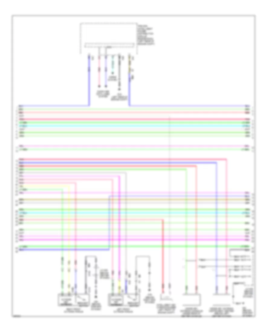
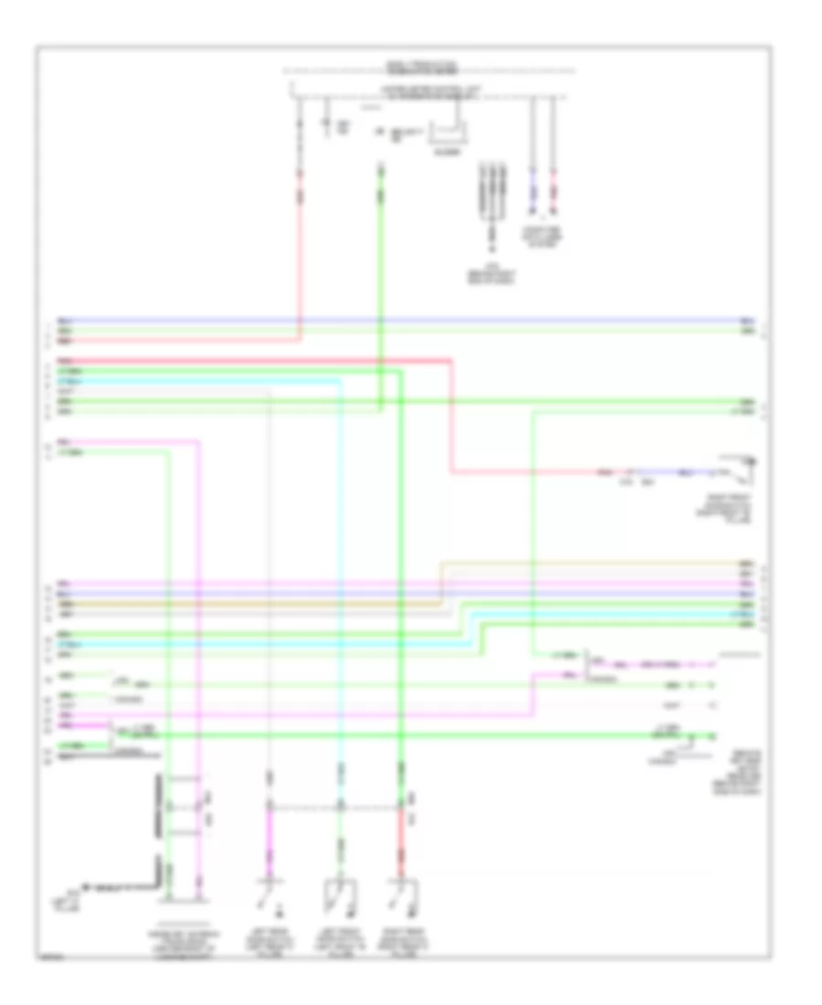
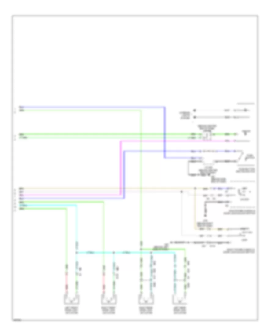
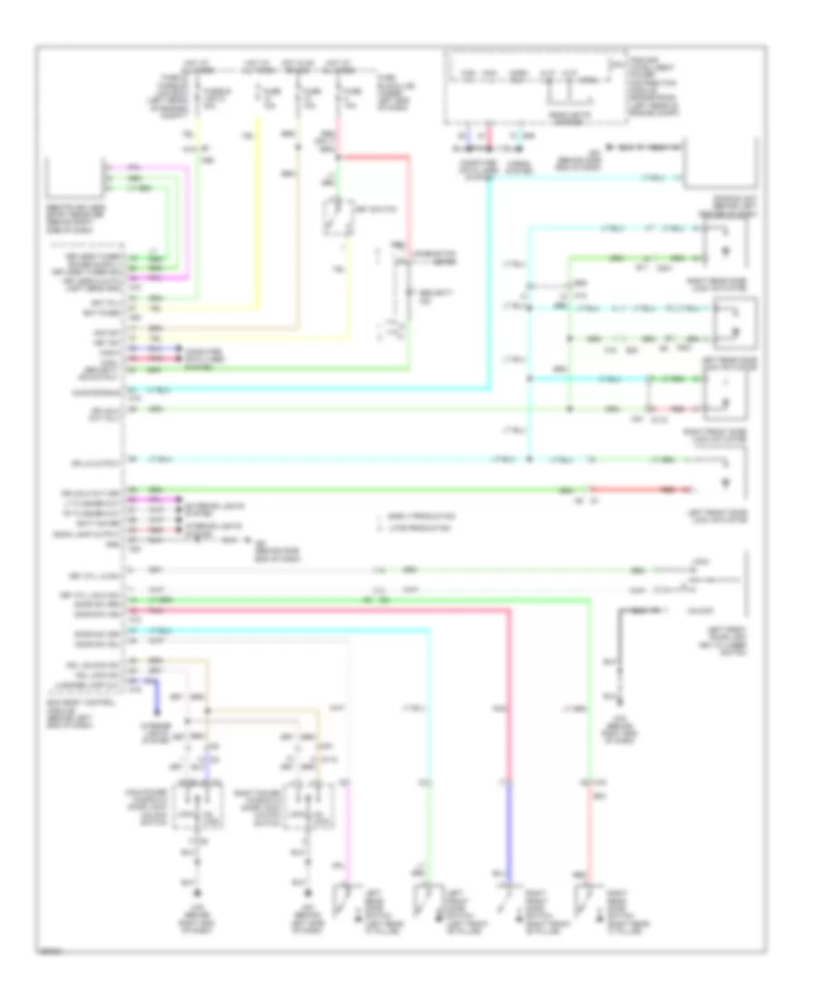
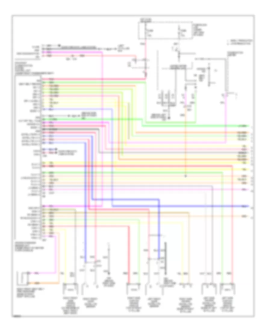
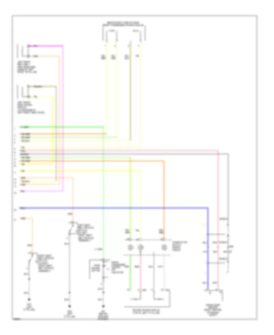
SUPPLEMENTAL RESTRAINTS Supplemental Restraints Wiring Diagram (1 of 2) for Nissan Versa S 2013 List of elements for Supplemental Restraints Wiring Diagram (1 of 2) for Nissan Versa S 2013: 81 (+) (-) (behind left side of dash) m57 (behind side end of dash) m61 (left "c" pillar) b19 Air bag diagnosis sensor unit (under front of center floor console) Air bag ind Air bag w/l As1 (+) As1 (-) As2 (+) As2 (-) B24 B37 C-lh1 (+) C-lh1(-) C-rh1 (+) C-rh1 (-) Can-h Can-l Combination meter Computer data lines system Cut off tell tale D101 Dr1 (+) Dr1 (-) & dr2 (-) Dr2 (+) Early production Eczs1 (+) Eczs1 (-) Fuse 10a Fuse block (j/b) (under left end of dash) Gnd Hot in on or start Ign J/c m5 K-line Late production Left front door satellite sensor Left side air bag (satellite) sensor (base of left "b" pillar) Left side curtain air bag module (top of left "c" pillar) Lh buckle sw (+) Lh sens (+) Lh sens (-) M16 M16 b24 M35 M75 M80 M84 (behind right side of dash) M85 (behind right side of dash) Nca Occupant classification system control unit (under front passenger's seat) Ods communication Ods input P-lh1 (+) P-lh1 (-) P-rh1 (+) P-rh1 (-) Pnk Red Rh buckle sw (+) Rh sens (+) Rh sens (-) Right front door satellite sensor Right front seat belt pre-tensioner (base of right right "b"pillar) Right front side air bag module (outer edge of right front seat back) Right side air bag (satellite) sensor (base of right "b" pillar) Right side curtain air bag module (top of right "c" pillar) S-lh1 (+) S-lh1 (-) S-rh (+) S-rh (-) Satellite lh (+) Satellite lh (-) Satellite rh (+) Satellite rh (-) Seat belt ind Seat belt remind Shield Unified meter control unit Supplemental Restraints Wiring Diagram (2 of 2) for Nissan Versa S 2013 List of elements for Supplemental Restraints Wiring Diagram (2 of 2) for Nissan Versa S 2013: 23 (+) (-) (behind right side of dash) front passenger air bag module 51a 62a 63a e7 B19 (left "c" pillar) Combination switch (spiral cable) Crash zone sensor (front center of engine compt) Driver air bag module (top of left "c" pillar) Front passenger air bag off indicator Left front seat belt pre-tensioner (base of left front "b" pillar) Left front side air bag module (outer edge of left front seat back) Left seat belt buckle switch (in left front seat belt buckle assembly) M61 (behind side end of dash) M69 M86 M87 Pass air bag off ind Pnk Red Right seat belt buckle switch (in right front seat belt buckle assembly) Shield
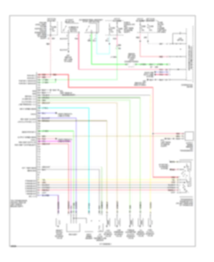
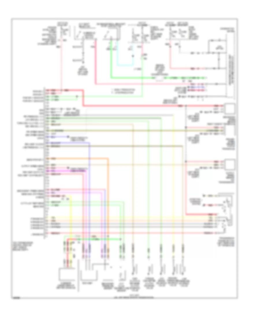
TRANSMISSION A/T Wiring Diagram for Nissan Versa S 2013 List of elements for A/T Wiring Diagram for Nissan Versa S 2013: 64 (behind left end of dash) joint connector-e02 (on brake pedal bracket) stop lamp switch 1 range sw 2 range sw 2-4 brake solenoid valve 2-4 brk sol vlv 92a A/t assembly A/t fluid temperature sensor A/t shift selector Aft- temp sens Brk sol vlv Can-h Can-l Clutch sol vlv Combination meter Computer data lines system D range sw E15 (left rear of E15 (left rear of engine compt) E45 E55 Engine compt) F55 Fuse & fusible link box (left rear of engine compt) Fuse 10a Fuse block (j/b) (under left end of dash) Gnd High clutch solenoid valve Hot at all times Hot in on or start Input speed sens Input speed sensor Ipdm e/r (intelligent power distribution module engine room) (left rear of engine compt) Line press sol vlv Line pressure solenoid valve Low clutch sol vlv Low clutch solenoid valve M57 (behind left side of dash) M69 N range sw O/d off ind Output speed sens Output speed sensor (on transmission) Overdrive control switch P range sw Pnk Pwr sply Pwr sply (backup) R range sw Red Rom assy (chip select) Rom assy (clock) Rom assy (data i/o) Rom-assy Select switch on-off solenoid valve Sens gnd Sens pwr sply Sol vlv Starting/ charging system Tcm (transmission control module) (left side of engine compt) Torque converter clutch solenoid valve Transmission range switch (on left rear side of transaxle) Unified meter control unit (w/ information display) CVT Wiring Diagram for Nissan Versa S 2013 List of elements for CVT Wiring Diagram for Nissan Versa S 2013: 71 (behind left end of dash) joint connector-e02 (on brake pedal bracket) stop lamp switch 11a 12a 22a 92a Can-h Can-l Combination meter Computer data lines system Cvt fluid temp sens Cvt fluid temperature sensor Cvt shift selector Cvt unit (on left rear side of transmission) D range sw E15 (left rear of engine compt) E45 E55 Early production F55 Fuse & fusible link box (left rear of engine compt) Fuse 10a Fuse block (j/b) (under left end of dash) G sens G sensor (under rear of center console) Gnd High clutch & reverse clutch solenoid valve Hot at all times Hot in on or start Ipdm e/r (intelligent power distribution module engine room) (left rear of engine compt) L range sw Late production Line press sol vlv Line pressure solenoid valve Low brake solenoid valve Low brk sol vlv M57 (behind left side of dash) M69 N range sw O/d off ind Output speed sens Output speed sensor (on transmission) Overdrive control switch P range sw Pnk Pri press sol vlv Pri speed sens Primary pressure solenoid valve Primary speed sensor (top of transaxle) Pwr sply Pwr sply (backup) R range sw Red Rev brk sol vlv Rom assy (chip select) Rom assy (clock) Rom assy (data i/o) Rom-assy Sec speed sens Secondary press sens Secondary pressure sensor Secondary speed sensor (right side of transaxle) Sens gnd Sens gnd (atf-pres) Sens pwr sply Starting/ charging system Tcm (transmission control module) (left side of engine compt) Torq conv clut sol vlv Torque converter clutch solenoid valve Transmission range switch (left rear side of transaxle) Unified meter control unit (w/ information display)
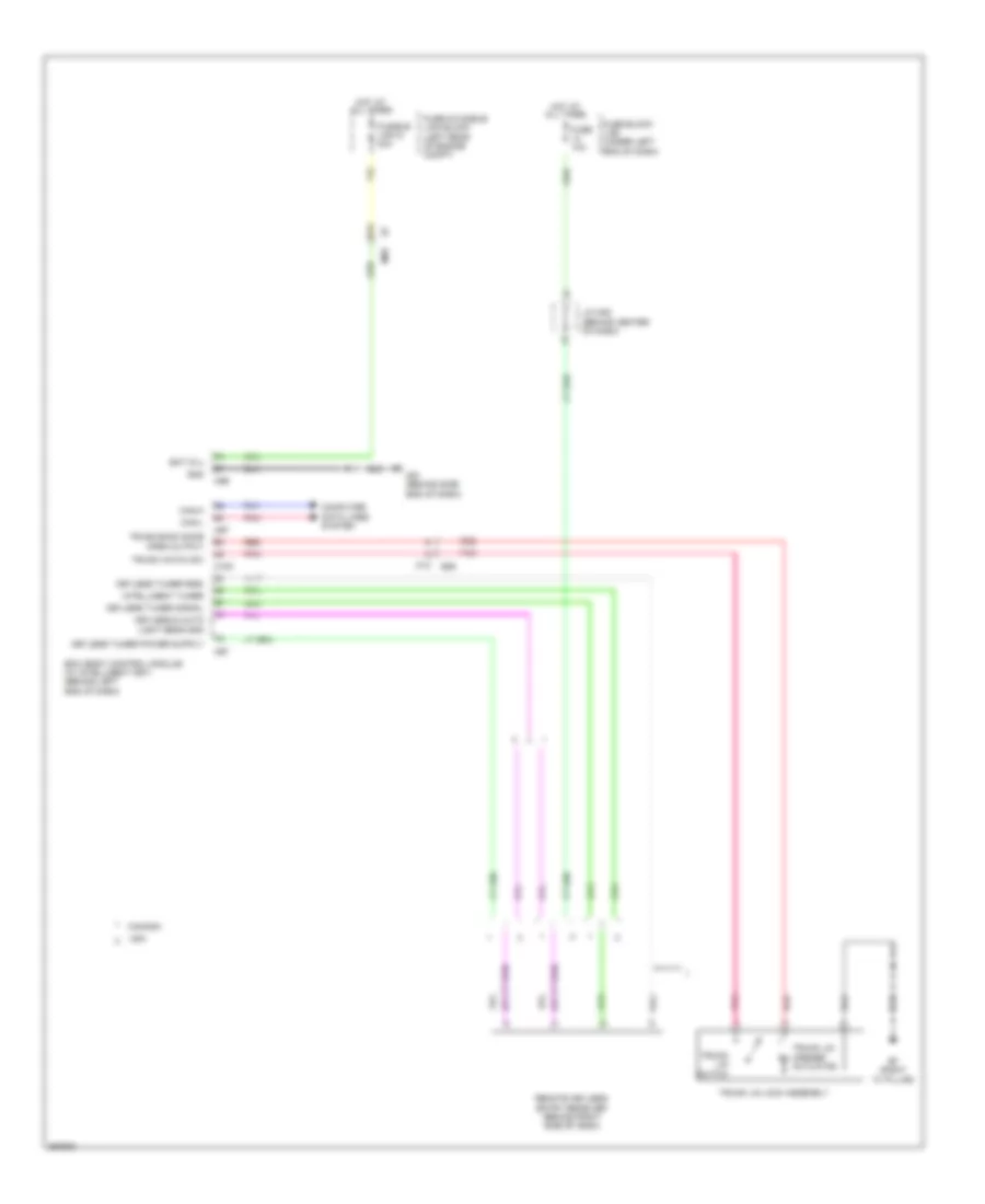
TRUNK, TAILGATE, FUEL DOOR Trunk Release Wiring Diagram for Nissan Versa S 2013 List of elements for Trunk Release Wiring Diagram for Nissan Versa S 2013: 35 91a B29 B7 (right "c" pillar) Bat (f/l) Bcm (body control module) (w/ intelligent key) (behind left end of dash) Can-h Can-l Canada Computer data lines system Fuse & fusible link block (left rear of engine compt) Fuse 10a Fuse block (j/b) (under left end of dash) Fusible link g 40a Gnd Hot at all times Intelligent tuner J/c m05 (behind center of dash) Keyless & auto light sens gnd Keyless tuner rssi Keyless tuner signal M100 M12 M61 (behind side end of dash) M69 M97 M99 Pnk Red Remote keyless entry receiver (behind right side of dash) Trunk back door open output Trunk hatch sw Trunk lid lock assembly Trunk lid opener actuator Trunk lid switch Usa
WARNING SYSTEMS Warning Systems Wiring Diagram, with Intelligent Key for Nissan Versa S 2013 List of elements for Warning Systems Wiring Diagram, with Intelligent Key for Nissan Versa S 2013: 67 (behind center of dash) j/c m05 37a 38a 91a B19 (left "c" pillar) B24 Bat Bat (f/l) Bat (fuse) Belt Body control module (bcm) (behind left end of dash) Brake ind Buzz output Buzzer Can-h Can-l Canada Combination meter (w/ information display) Combination switch Computer data lines system Door sw (dr) Early production Fuse & fusible link box (left rear of engine compt) Fuse 10a Fuse block (j/b) (under left end of dash) Fusible link g 40a Gnd (pwr) Hot at all times Hot in on or start Ign Input 1 Input 2 Input 3 Input 4 Input 5 Intelligent key warning buzzer (left front of engine compt) Intelligent turner Key les & auto sens gnd Key les turn pwr sup Key les turn rssi Key les turn sig Late production Left front door switch (left front "b" pillar) Left seat belt buckle switch (in left front seat belt buckle assembly) M100 M16 M16 b24 M28 M57 (behind left side of dash) M61 (behind side end of dash) M69 M97 M98 M99 Output 1 Output 2 Output 3 Output 4 Output 5 Parking brake switch (base of parking brake lever assembly) Pnk Red Remote keyless entry receiver (behind right side of dash) Seat belt ind Tire pressure ind Unified meter control unit Usa Warning Systems Wiring Diagram, without Intelligent Key for Nissan Versa S 2013 List of elements for Warning Systems Wiring Diagram, without Intelligent Key for Nissan Versa S 2013: 60 91a B19 (left "c" pillar) B24 Bat Bat (f/l) Bat (fuse) Belt Body control module (bcm) (behind left end of dash) Brake ind Buzzer Can-h Can-l Combination meter (w/ information display) Combination switch Computer data lines system Door sw (dr) Early production Fuse & fusible link box (left rear of engine compt) Fuse 10a Fuse block (j/b) (under left end of dash) Fusible link g 40a Gnd (pwr) Hot at all times Hot in on or start Ign Ign sw Input 1 Input 2 Input 3 Input 4 Input 5 Key les & auto sens gnd Key les turn pwr sup Key les turn sig Key sw Key switch Late production Left front door switch (left front "b" pillar) Left seat belt buckle switch (in left front seat belt buckle assembly) M16 M16 b24 M18 M19 M20 M28 M57 (behind left side of dash) M61 (behind side end of dash) M69 Output 1 Output 2 Output 3 Output 4 Output 5 Parking brake switch (base of parking brake lever assembly) Pnk Red Remote keyless entry receiver (behind right side of dash) Seat belt ind Tire pressure ind Unified meter control unit
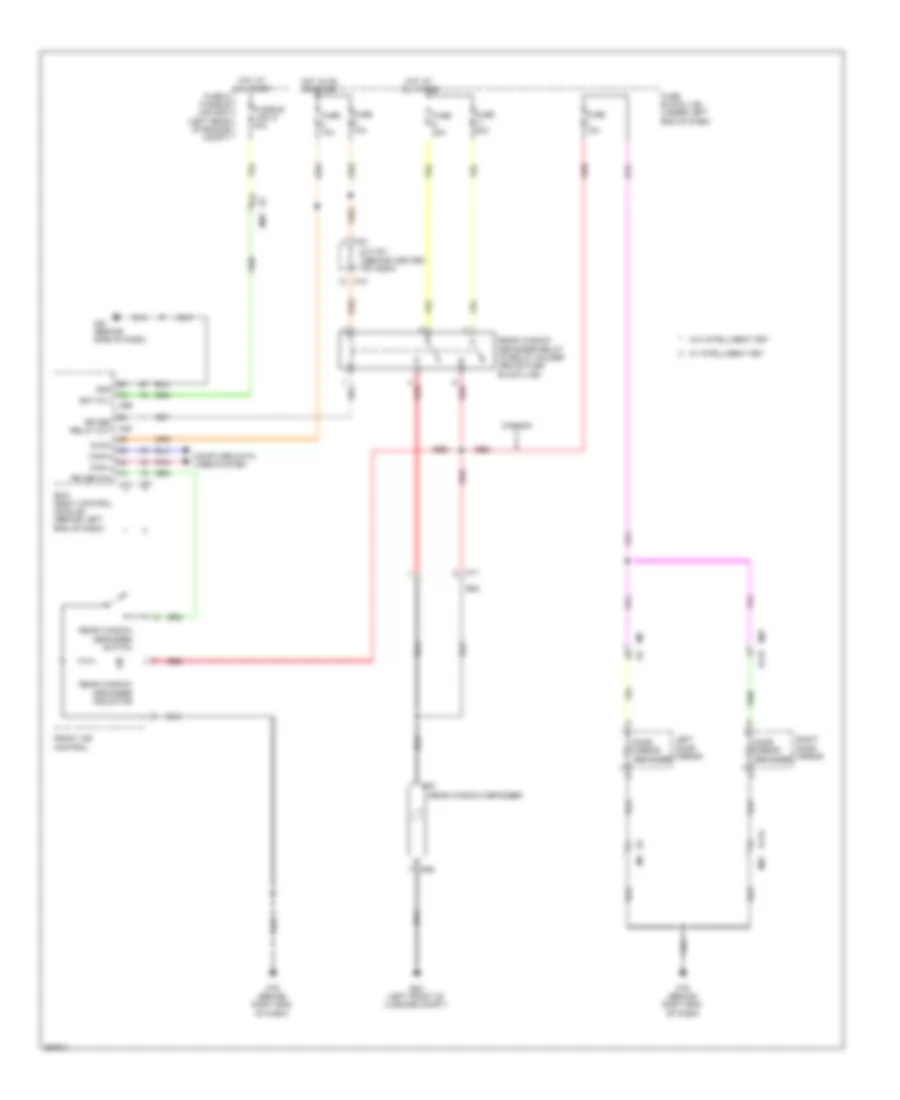
WIPER/WASHER Wiper/Washer Wiring Diagram for Nissan Versa S 2013 List of elements for Wiper/Washer Wiring Diagram for Nissan Versa S 2013: 61 29a Bat (f/l) Body control module (bcm) (behind left end of dash) Brake fluid level switch (on brake fluid reservoir) Can-h Can-l Combination meter Combination switch (wiper & washer switch) Computer data lines system Cpu E15 (left rear of engine compt) E24 (right rear of engine compt) E45 E46 E7 18a E7 91a Early production Front washer motor (in washer fluid reservoir) Front wiper high relay Front wiper motor (left side of firewall) Front wiper relay Fuse & fusible link box (left rear of engine compt) Fuse 10a Fuse 30a Fuse block (j/b) (under left end of dash) Fusible link g 40a Gnd Hot at all times Hot in on or start Ignition relay 1 Input 1 Input 2 Input 3 Input 4 Input 5 Ipdm e/r (intelligent power distribution module engine room) (left rear of engine compt) Late production M18 M20 M28 M57 (behind left side of dash) M61 (behind side end of dash) M69 M79 (behind right end of dash) M97 M99 Move Output 1 Output 2 Output 3 Output 4 Output 5 Pnk Red Stop Unified meter control unit (w/ inform- ation display) W/ intelligent key system W/o intelligent key system Wash mtr Washer ind (canada) Washer level fluid switch (canada) (in washer fluid reservoir)