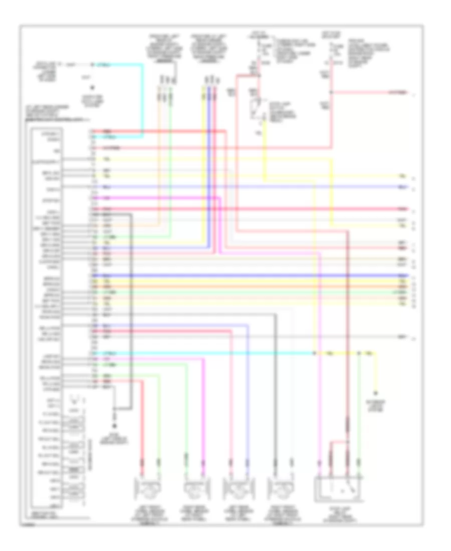
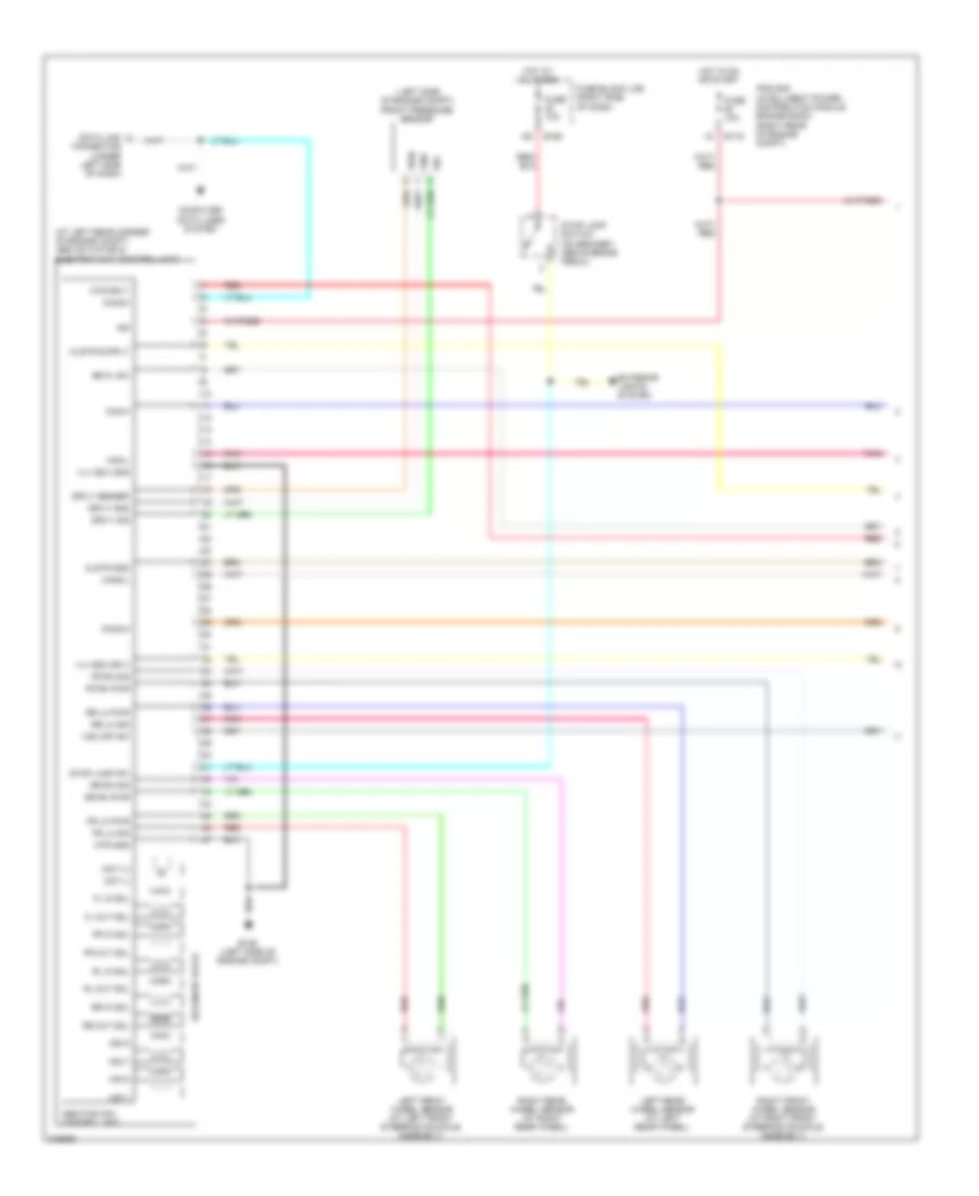
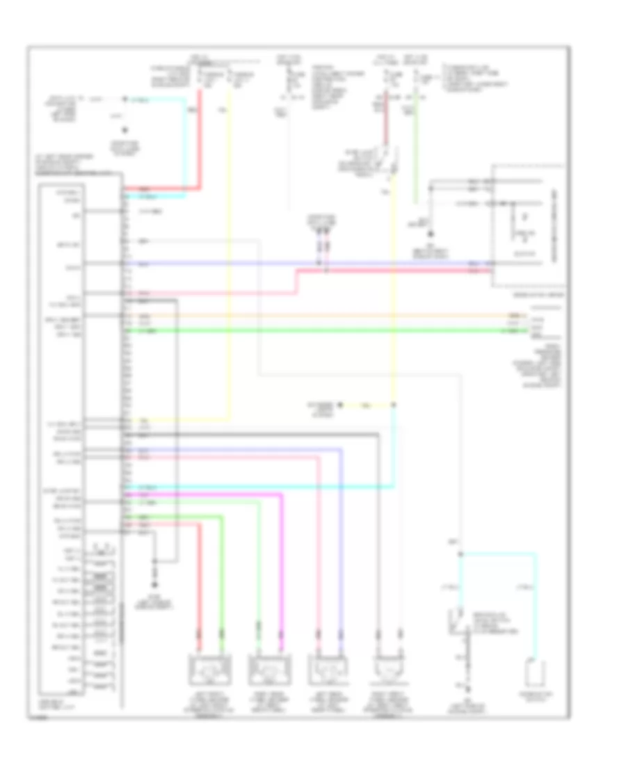
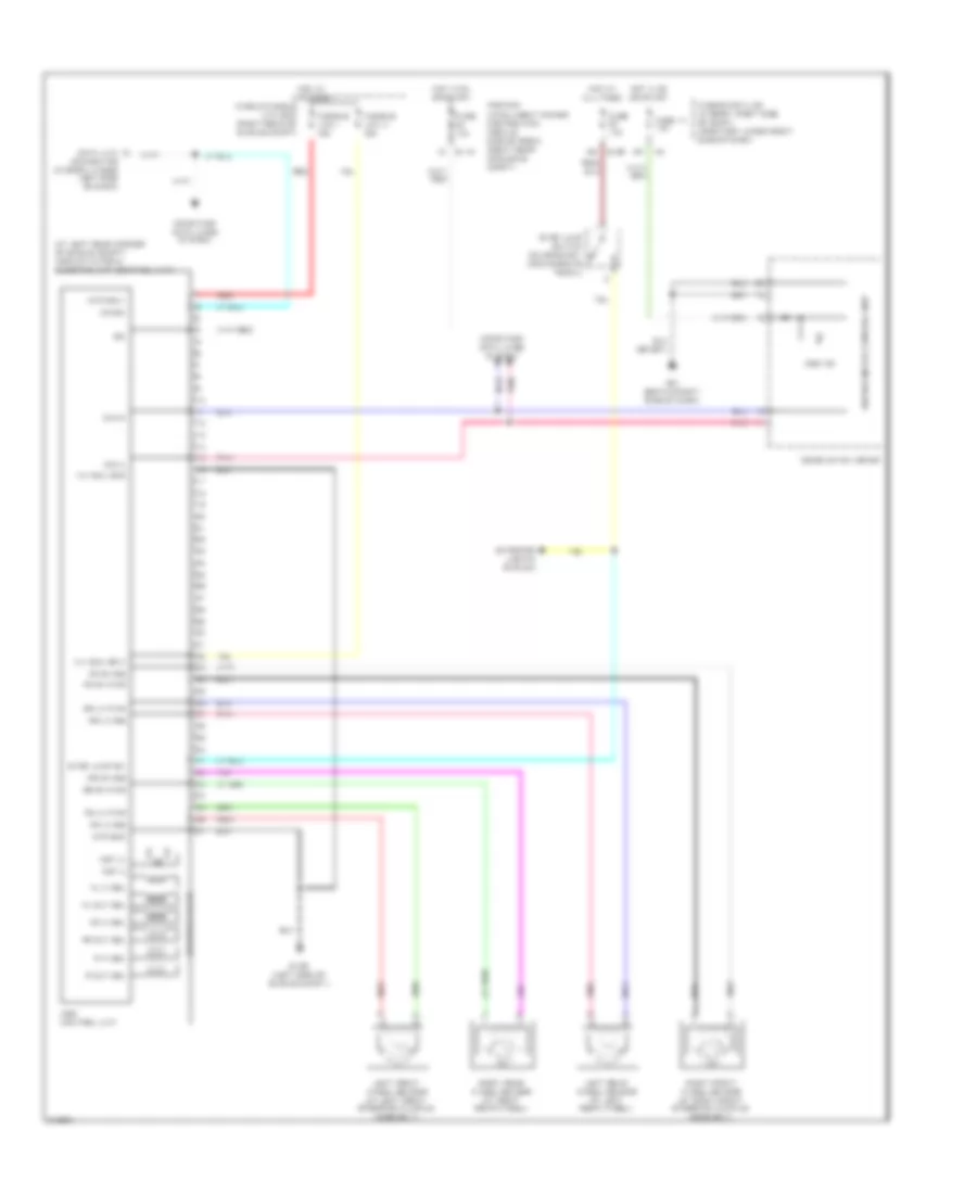
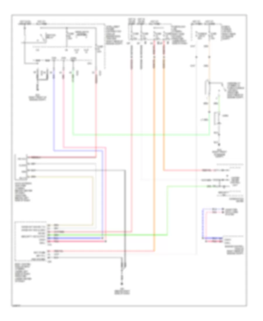
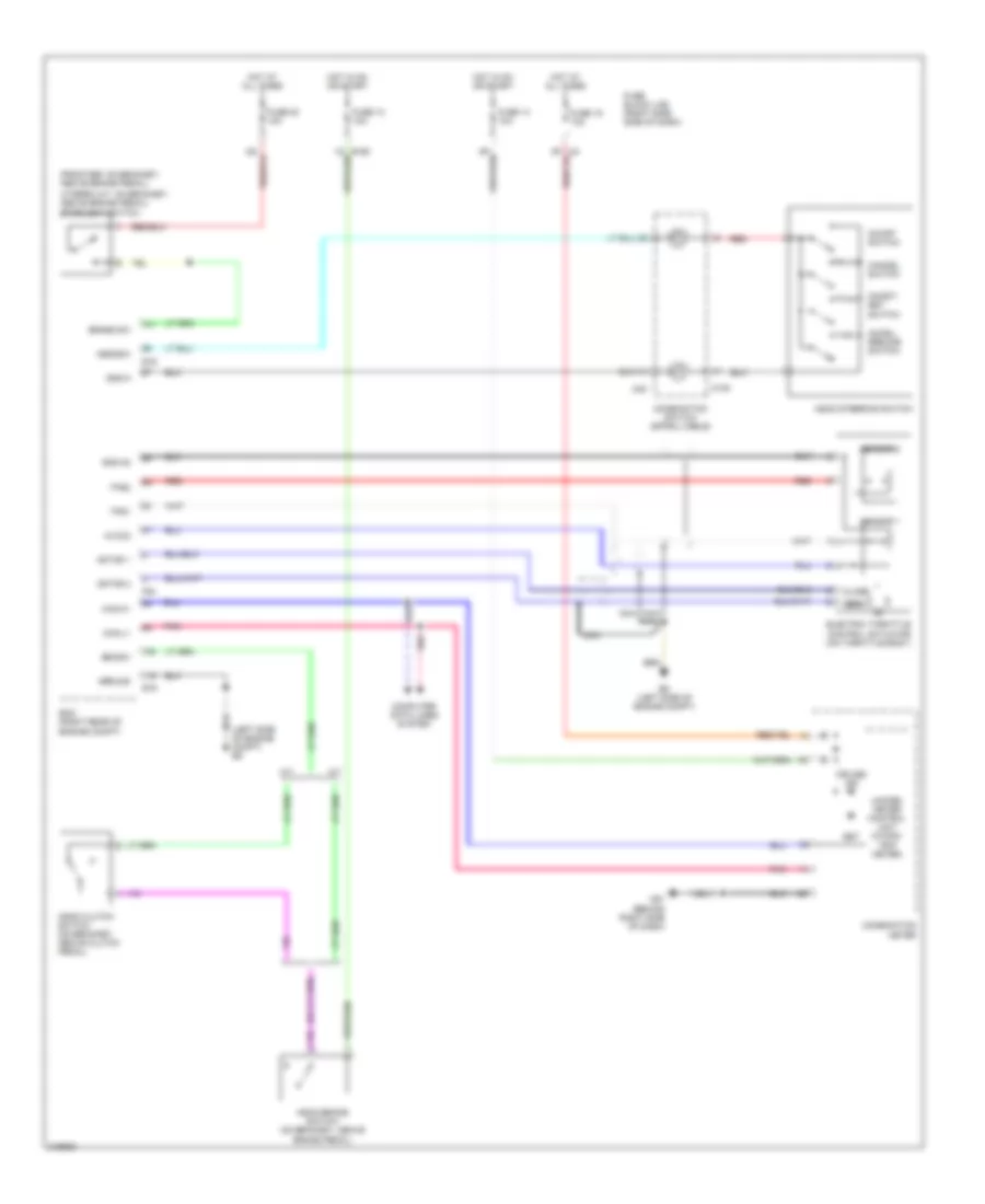
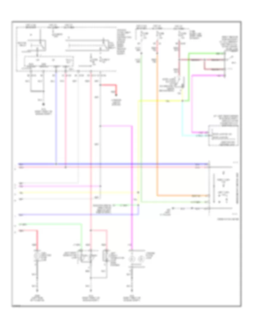
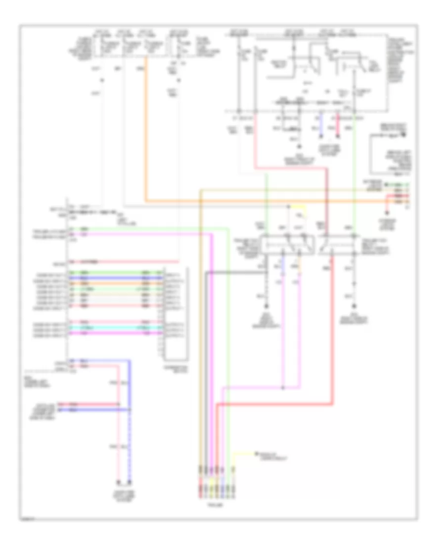
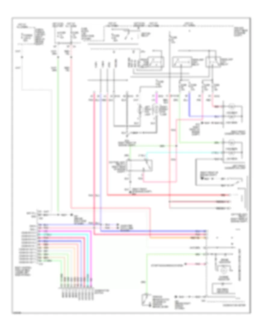
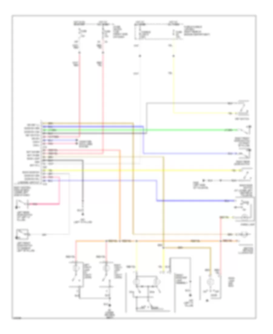
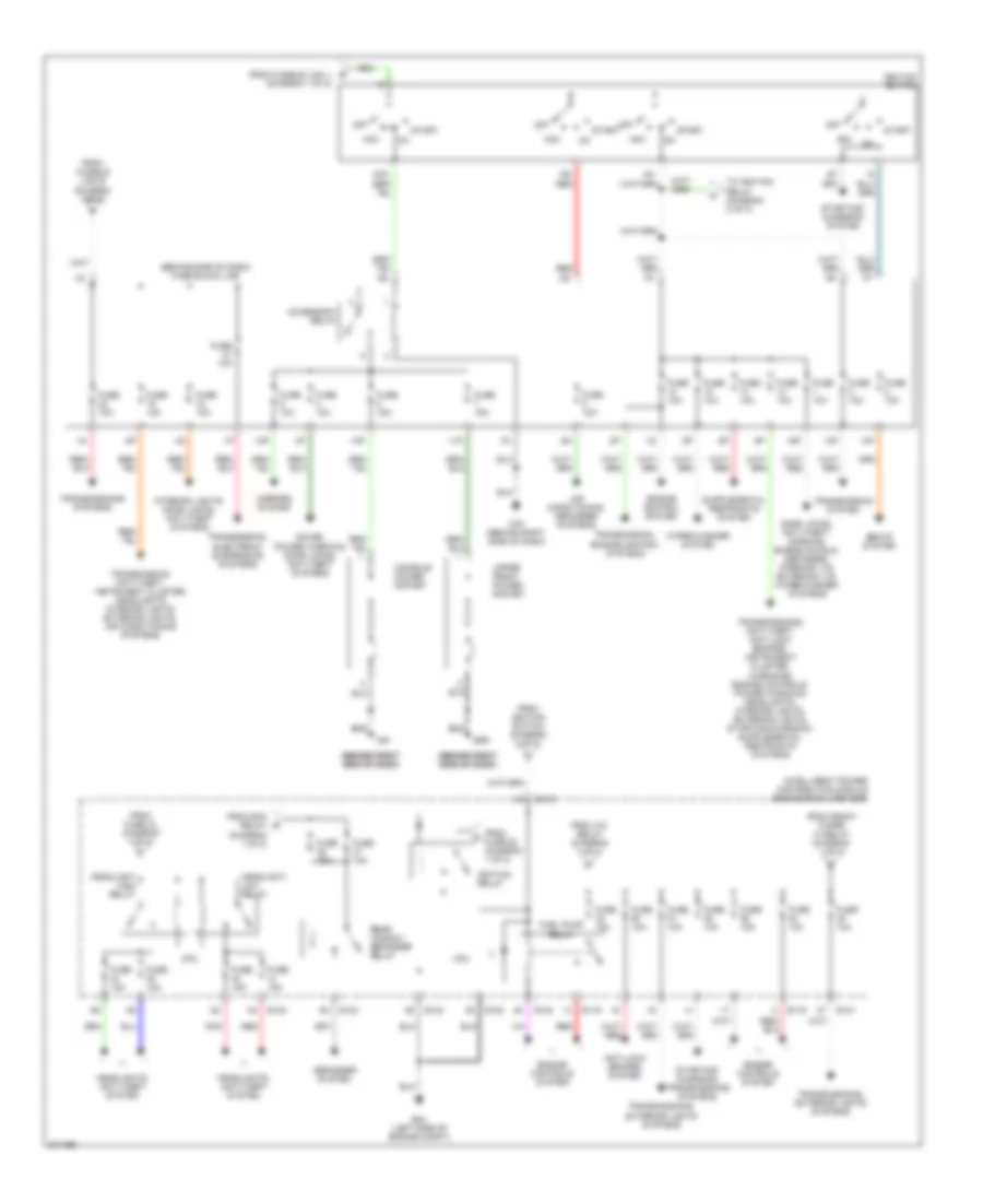
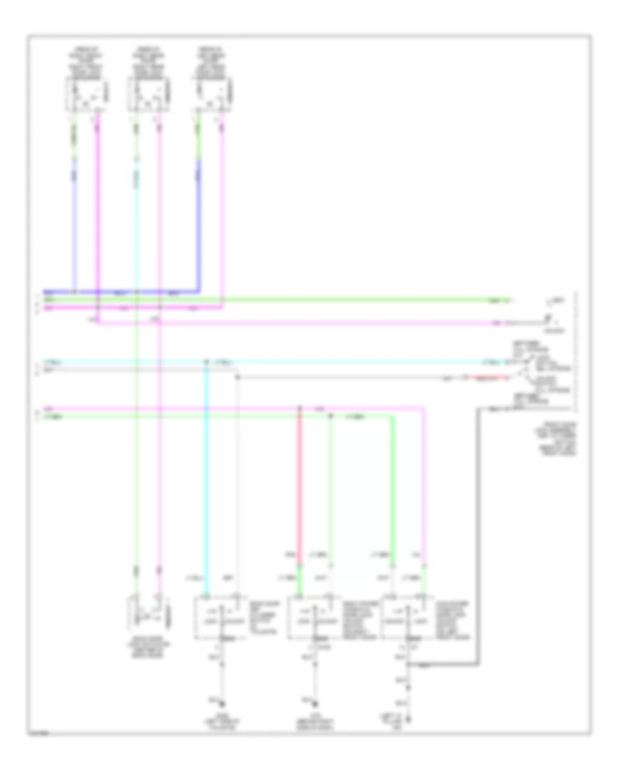
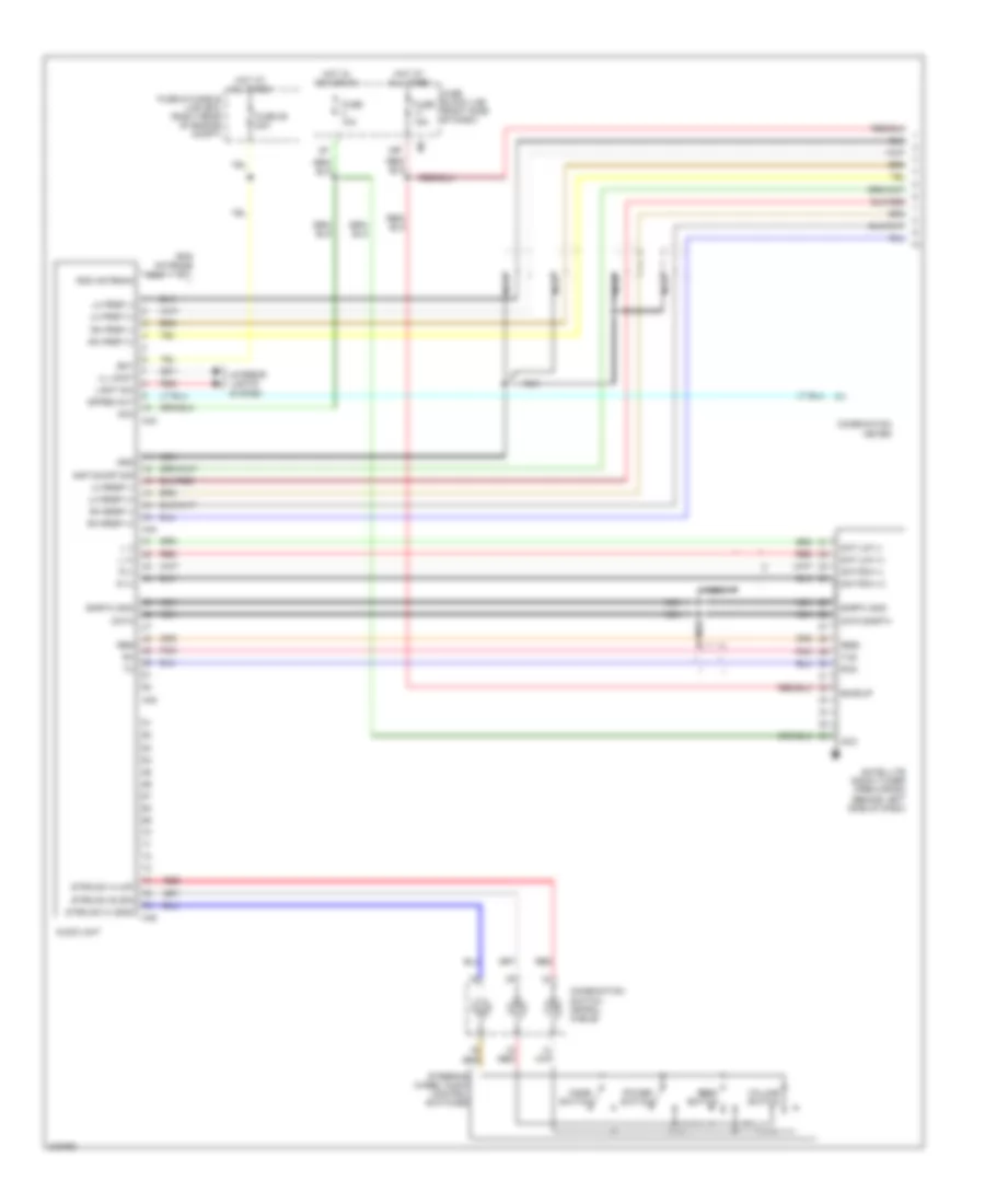
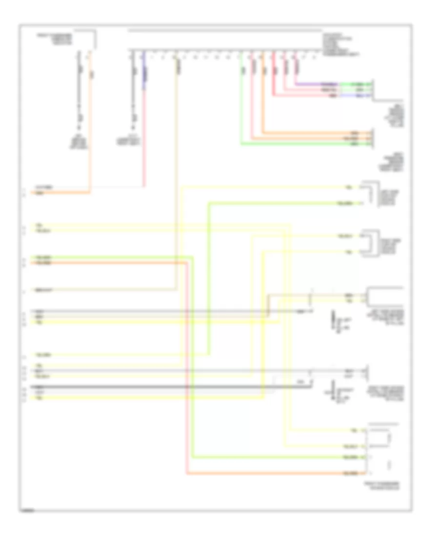
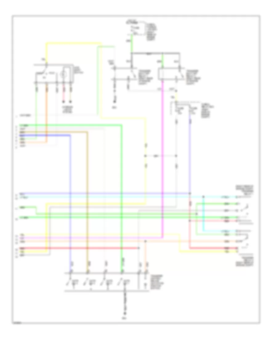
AIR CONDITIONING
Manual A/C Wiring Diagram for Nissan Xterra Off Road 2005

List of elements for Manual A/C Wiring Diagram for Nissan Xterra Off Road 2005:
- (behind right side of dash, on intake unit)
- (front of engine compt) cooling fan motor
- (right side of dash)
- A/c compressor (at left front of engine)
- A/c relay
- A/c request
- As blend dr ccw
- As blend dr cw
- Avcc
- Bat
- Blend feed back
- Body control module (under left side of dash)
- Can-h
- Can-l
- Computer data lines system
- Cooling fan high relay
- Cooling fan low relay
- Cpu
- Defogger system
- E119
- E120
- E122
- E15 (right front of engine compt)
- E16
- Ecm (right rear of engine compt)
- Engine coolant temperature sensor (at rear of engine)
- F54
- Fan on
- Fr blower
- Front air control (behind center of dash)
- Front air mix door motor (behind center of dash)
- Front blower motor (behind glove box, on intake unit)
- Front blower motor relay (right rear of engine compt)
- Front blower motor resistor (behind right side of dash)
- Front blower switch
- Fuse & fusible link box (right rear of engine compt)
- Fuse 10a
- Fuse 15a
- Fuse block (j/b)
- Fuse j 40a
- Gnd
- Gnd a
- Hot at all times
- Hot in on or start
- Ign
- Ill+
- Ill-
- Intake door motor
- Intake sensor
- Intake sensor (behind right side of dash)
- Interior lights system
- Ipdm e/r (intelligent power distribution module engine room) (right rear of engine compt)
- M18
- M57 (left "a" pillar)
- M61 (behind right side of dash)
- Mode door motor (behind center of dash)
- Mode feed back
- Off
- Panel/floor ccw
- Panel/floor cw
- Pdpress
- Pnk
- Recirc door ccw
- Recirc door cw
- Red
- Refrigerant pressure sensor (front of engine compt)
- Rr def request
- Rr def status
- Rr def sw
- Sens return
- V ref actr (5v)
- V ref actr (gnd)
ANTI-LOCK BRAKES
Anti-lock Brakes Wiring Diagram, with Traction Control & Stability Assist with Hill Assist (1 of 2) for Nissan Xterra Off Road 2005
List of elements for Anti-lock Brakes Wiring Diagram, with Traction Control & Stability Assist with Hill Assist (1 of 2) for Nissan Xterra Off Road 2005:
- (at left rear corner of engine compt) abs actuator & electric unit (control unit)
- (frontier: at left rear corner of engine compt) (xterra: left side of engine compt) rear pressure sensor
- (frontier: left rear of engine compt) (xterra: left side of engine compt) front pressure sensor
- Abs/tcs/vdc control unit
- Bpfs nc
- Bpfs no
- Bpfs sig
- Br fl sw
- Bst pwm
- Bst pwr
- Can1-h
- Can1-l
- Can2-h
- Can2-l
- Clstr gnd
- Computer data lines system
- Data link connector (under left side of dash)
- Diag-k
- Driv1 gnd
- Driv1 sensep
- Driv1 sig
- Driv2 gnd
- Driv2 sig
- Driv2 sp
- E119
- E126 (left side of engine compt)
- E160
- Exterior lights system
- Fl in sol
- Fl out sol
- Fr in sol
- Fr lh pwr
- Fr lh sig
- Fr out sol
- Fr rh pwr
- Fr rh sig
- Fuse 10a
- Fuse block (j/b) (xterra: right side of dash) (frontier: under right side of dash)
- Gnd
- Hdc sw
- Hot at all times
- Hot in on or start
- Hsv1
- Hsv2
- Ign
- Ipdm e/r (intelligent power distribution module engine room) (right rear of engine compt)
- Lamp sw
- Left front wheel sensor (at left front steering knuckle assembly)
- Left rear wheel sensor (at left rear wheel)
- Mot (+)
- Mot (-)
- Mtr gnd
- Mtr sply
- Pnk
- Pwr
- Red
- Right front wheel sensor (at right front steering knuckle assembly)
- Right rear wheel sensor (at right rear wheel)
- Rl in sol
- Rl out sol
- Rr in sol
- Rr lh pwr
- Rr lh sig
- Rr out sol
- Rr rh pwr
- Rr rh sig
- Sig
- Solenoid valve
- Stop lamp relay (right rear of engine compt)
- Stop lamp switch (on bracket, above brake pedal)
- Stop sw
- Usv1
- Usv2
- Vdc off sw
- Vlv ecu gnd
- Vlv ecu sply
Anti-lock Brakes Wiring Diagram, with Traction Control & Stability Assist with Hill Assist (2 of 2) for Nissan Xterra Off Road 2005
List of elements for Anti-lock Brakes Wiring Diagram, with Traction Control & Stability Assist with Hill Assist (2 of 2) for Nissan Xterra Off Road 2005:
- (behind right side of dash) m61
- (below left side of dash, near steering column) steering angle sensor
- Abs ind
- Active booster (left rear of engine compt)
- Batt
- Brake fluid level switch (in brake fluid reservoir)
- Can-h
- Can-l
- Clu gnd
- Clu p
- Combination meter
- Combination switch
- Computer data lines system
- E9 (left side of engine compt)
- Frontier
- Fuse & fusible link box (right rear of engine compt)
- Fuse 14 10a
- Fuse 21 10a
- Fuse block (j/b) (xterra: right side of dash) (frontier: under right side of dash)
- Fusible link i 40a
- Fusible link n 30a
- Gnd
- Hdc
- Hdc switch
- Hot at all times
- Hot in on or start
- Interior lights system
- M61 (behind right side of dash)
- Pnk
- Pwr
- Red
- Slip ind
- Unified meter control unit
- Vdc off ind
- Vdc off switch
- Xterra
- Yaw rate/side/decel g sensor (xterra: under rear of center console) (frontier crew cab: under center console) (frontier king cab: beneath center console)
Anti-lock Brakes Wiring Diagram, with Traction Control & Stability Assist, without Hill Assist (1 of 2) for Nissan Xterra Off Road 2005
List of elements for Anti-lock Brakes Wiring Diagram, with Traction Control & Stability Assist, without Hill Assist (1 of 2) for Nissan Xterra Off Road 2005:
- ( left side of engine compt)
- (at left rear corner of engine compt) abs actuator & electric unit (control unit)
- Abs/tcs/vdc control unit
- Br fl sw
- Can-h
- Can-l
- Can2-h
- Can2-l
- Clstr gnd
- Computer data lines system
- Data link connector (under left side of dash)
- Diag-k
- Driv1 gnd
- Driv1 sensep
- Driv1 sig
- E119
- E126 (left side of engine compt)
- E160
- Exterior lights system
- Fl in sol
- Fl out sol
- Fr in sol
- Fr lh pwr
- Fr lh sig
- Fr out sol
- Fr rh pwr
- Fr rh sig
- Front pressure sensor
- Fuse 10a
- Fuse block (j/b) (right side of dash)
- Gnd
- Hot at all times
- Hot in on or start
- Hsv1
- Hsv2
- Ign
- Ipdm e/r (intelligent power distribution module engine room) (right rear of engine compt)
- Left front wheel sensor (at left front steering knuckle assembly)
- Left rear wheel sensor (at left rear wheel)
- Mot (+)
- Mot (-)
- Mtr gnd
- Mtr sply
- Pnk
- Pwr
- Red
- Right front wheel sensor (at right front steering knuckle assembly)
- Right rear wheel sensor (at right rear wheel)
- Rl in sol
- Rl out sol
- Rr in sol
- Rr lh pwr
- Rr lh sig
- Rr out sol
- Rr rh pwr
- Rr rh sig
- Sig
- Solenoid valve
- Stop lamp sw
- Stop lamp switch (on bracket, above brake pedal)
- Usv1
- Usv2
- Vdc off sw
- Vlv ecu gnd
- Vlv ecu sply
Anti-lock Brakes Wiring Diagram, with Traction Control & Stability Assist, without Hill Assist (2 of 2) for Nissan Xterra Off Road 2005
List of elements for Anti-lock Brakes Wiring Diagram, with Traction Control & Stability Assist, without Hill Assist (2 of 2) for Nissan Xterra Off Road 2005:
- (below left side of dash, near steering column) steering angle sensor
- Abs ind
- Batt
- Brake fluid level switch (in brake fluid reservoir)
- Can-h
- Can-l
- Clu gnd
- Clu p
- Combination meter
- Combination switch
- Computer data lines system
- E9 (left side of engine compt)
- Fuse & fusible link box (right rear of engine compt)
- Fuse 14 10a
- Fuse 21 10a
- Fuse block (j/b) (right side of dash)
- Fusible link i 40a
- Fusible link n 30a
- Gnd
- Hot at all times
- Hot in on or start
- Interior lights system
- M61 (behind right side of dash)
- Pnk
- Pwr
- Red
- Slip ind
- Unified meter control unit
- Vdc off ind
- Vdc off switch
- Yaw rate/side/decel g sensor (under rear of center console)
Anti-lock Brakes Wiring Diagram, with Traction Control for Nissan Xterra Off Road 2005
List of elements for Anti-lock Brakes Wiring Diagram, with Traction Control for Nissan Xterra Off Road 2005:
- (at left rear corner of engine compt) abs actuator & electric unit (control unit)
- Abs ind
- Abs/abls control unit
- Br fl sw
- Brake fluid level switch (in brake fluid reservoir)
- Can-h
- Can-l
- Combination meter
- Combination switch
- Computer data lines system
- Data link connector (under left side of dash)
- Diag-k
- Driv1 gnd
- Driv1 sensep
- Driv1 sig
- E119
- E126 (left side of engine compt)
- E160
- E9 (left side of engine compt)
- Exterior lights system
- Fl in sol
- Fl out sol
- Fr in sol
- Fr lh pwr
- Fr lh sig
- Fr out sol
- Fr rh pwr
- Fr rh sig
- Front pressure sensor (xterra: left side of engine compt) (frontier: left rear of engine compt)
- Fuse & fusible link box (right rear of engine compt)
- Fuse 10a
- Fuse 14 10a
- Fuse block (j/b) (xterra: right side of dash) (frontier: under right side of dash)
- Fusible link i 40a
- Fusible link n 30a
- Gnd
- Hot at all times
- Hot in on or start
- Hsv1
- Hsv2
- Ign
- Ipdm e/r (intelligent power distribution module engine room) (right rear of engine compt)
- Left front wheel sensor (at left front steering knuckle assembly)
- Left rear wheel sensor (at left rear wheel)
- M61 (behind right side of dash)
- Mot (+)
- Mot (-)
- Mtr gnd
- Mtr sply
- Pnk
- Pwr
- Red
- Right front wheel sensor (at right front steering knuckle assembly)
- Right rear wheel sensor (at right rear wheel)
- Rl in sol
- Rl out sol
- Rr in sol
- Rr lh pwr
- Rr lh sig
- Rr out sol
- Rr rh pwr
- Rr rh sig
- Sig
- Slip ind
- Solenoid valve
- Stop lamp sw
- Stop lamp switch (on bracket, above brake pedal)
- Unified meter control unit
- Usv1
- Usv2
- Vlv ecu gnd
- Vlv ecu sply
Anti-lock Brakes Wiring Diagram, without Traction Control for Nissan Xterra Off Road 2005
List of elements for Anti-lock Brakes Wiring Diagram, without Traction Control for Nissan Xterra Off Road 2005:
- (at left rear corner of engine compt) abs actuator & electric unit (control unit)
- Abs control unit
- Abs ind
- Can-h
- Can-l
- Combination meter
- Computer data lines system
- Data link connector (xterra: under left side of dash)
- Diag-k
- E119
- E126 (left side of engine compt)
- E160
- Exterior lights system
- Fl in sol
- Fl out sol
- Fr in sol
- Fr lh pwr
- Fr lh sig
- Fr out sol
- Fr rh pwr
- Fr rh sig
- Fuse & fusible link box (right rear of engine compt)
- Fuse 10a
- Fuse 14 10a
- Fuse block (j/b) (xterra: right side of dash) (frontier: under right side of dash)
- Fusible link i 40a
- Fusible link n 30a
- Hot at all times
- Hot in on or start
- Ign
- Ipdm e/r (intelligent power distribution module engine room) (right rear of engine compt)
- Left front wheel sensor (at left front steering knuckle assembly)
- Left rear wheel sensor (at left rear wheel)
- M61 (behind right side of dash)
- Mot (+)
- Mot (-)
- Mtr gnd
- Mtr sply
- Pnk
- R in sol
- R out sol
- Red
- Right front wheel sensor (at right front steering knuckle assembly)
- Right rear wheel sensor (at right rear wheel)
- Rr lh pwr
- Rr lh sig
- Rr rh pwr
- Rr rh sig
- Solenoid valve
- Stop lamp sw
- Stop lamp switch (on bracket, above brake pedal)
- Unified meter control unit
- Vlv ecu gnd
- Vlv ecu sply
ANTI-THEFT
Forced Entry Wiring Diagram (1 of 2) for Nissan Xterra Off Road 2005
List of elements for Forced Entry Wiring Diagram (1 of 2) for Nissan Xterra Off Road 2005:
- 4p m4
- Acc sw
- Back door key cylinder switch (at lower right center of tailgate)
- Back door switch (at lower left center of tailgate)
- Bat
- Bat (f/l)
- Body control module (bcm) (under left side of dash)
- Can-h
- Can-l
- Cdl lock sw
- Cdl unlock sw
- Combination meter
- Computer data lines system
- D406 (left side of tailgate)
- Door lift gate
- Door sw (as)
- Door sw (dr)
- Door sw (rl)
- Door sw (rr)
- Fuse & fusible link box (right rear of engine compt)
- Fuse 10a
- Fuse block (j/b) (right side of dash)
- Fusible link g 50a
- Gnd
- Gnd (power)
- Hot at all times
- Hot in acc or on
- Hot in on or start
- Key cylinder lock sw
- Key cylinder unlock sw
- Left front door switch (at base of left "b" pillar)
- Left rear door switch (at left "c" pillar)
- Lock
- M18
- M19
- M20
- M3 4n
- M61 (behind right side of dash)
- Pnk
- Right front door switch (at right "b" pillar)
- Right rear door switch (at right "c" pillar)
- Security ind lamp
- Security ind output
- United meter control unit
- Unlock
Forced Entry Wiring Diagram (2 of 2) for Nissan Xterra Off Road 2005
List of elements for Forced Entry Wiring Diagram (2 of 2) for Nissan Xterra Off Road 2005:
- (behind right side of dash) m61
- (left "a" pillar) m57
- +ig
- Between full stroke & n
- Can h
- Can l
- Cpu
- E122
- E123
- E124
- E15 (right front of engine compt)
- Front door lock assembly (key cylinder switch)
- Full stroke
- Fuse & fusible link box (right rear of engine compt)
- Fuse 10a
- Fuse 15a
- Fuse 20a
- Gnd
- Gnd (sig)
- H/lp hi
- H/lp lo
- Headlamp high relay
- Headlamp low relay
- Headlights system
- Horn
- Horn relay (in fuse & fusible link box)
- Horn rly
- Hot at all times
- Hot in on or start
- Ignition relay
- Intelligent power distribution module engine room (ipdm e/r) (right rear of engine compt)
- Lock
- Lock switch
- Main power window & door lock/ unlock switch
- Pnk
- Red
- Right power window & door lock/ unlock switch
- Unlock
- Unlock switch
Immobilizer Wiring Diagram for Nissan Xterra Off Road 2005
List of elements for Immobilizer Wiring Diagram for Nissan Xterra Off Road 2005:
- +ig
- 15p
- Bat (f/l)
- Bat (fuse)
- Body control module (bcm) (xterra: under left side of dash) (frontier: under center of dash)
- Can h
- Can l
- Can-h
- Can-l
- Clock
- Combination meter
- Computer data lines system
- Cpu
- E121
- E122
- E124
- E15 (right front of engine compt)
- Engine control module (right rear of engine compt)
- Fuse & fusible link box (right rear of engine compt)
- Fuse 10a
- Fuse 15a
- Fuse 20a
- Fuse block (j/b) (xterra: right side of dash) (frontier: under right side of dash)
- Fusible link g 50a
- Gnd
- Gnd (power)
- H/lp hi
- H/lp lo
- Headlights system
- Horn
- Horn relay (xterra: in fuse & fusible link box) (frontier: right rear of engine compt)
- Horn rly
- Hot at all times
- Hot in on and start
- Hot in on or start
- Ign sw
- Ignition relay
- Immob ant sig (clock)
- Immob ant sig (rx, tx)
- Intelligent power distribution module engine room (ipdm e/r) (right rear of engine compt)
- M18
- M20
- M61 (behind right side of dash)
- Nats antenna amplifier (xterra: behind center of dash) (frontier: behind left side of dash)
- Pnk
- Rx,tx
- Security ind
- Security ind output
- Unified meter control unit
- Vb (12v)
BODY CONTROL MODULES
Body Control Modules Wiring Diagram for Nissan Xterra Off Road 2005
List of elements for Body Control Modules Wiring Diagram for Nissan Xterra Off Road 2005:
- 15p
- A/c request
- Acc sw
- Air conditioning system
- Ant sig (clock)
- Ant sig (rx, tx)
- Anti-theft system
- Auto stop
- Back door sw
- Bat (f/l)
- Bat (fuse)
- Bat saver out
- Bcm (body control module) (under left side of dash)
- Can-h
- Can-l
- Cdl lock sw
- Cdl unlock sw
- Comb sw in 1
- Comb sw in 2
- Comb sw in 3
- Comb sw in 4
- Comb sw in 5
- Comb sw out 1
- Comb sw out 2
- Comb sw out 3
- Comb sw out 4
- Comb sw out 5
- Computer data lines system
- Defogger system
- Door locks system
- Door sw (as)
- Door sw (dr)
- Door sw (rl)
- Door sw (rr)
- Dr lock out (all)
- Dr unlock out (dr)
- Dr unlock out (otr)
- Exterior lights system
- Fan on
- Flasher out (lh)
- Flasher out (rh)
- Fuse & fusible link box (right rear of engine compt)
- Fuse 10a
- Fuse block (j/b) (right side of dash)
- Fusible link 25 10a
- Fusible link g 50a
- Gnd (pwr)
- Hazard sw
- Headlights system
- Hot at all times
- Hot in on or acc
- Hot in on or start
- Ign key ill
- Ign sw
- Interior lights system
- Key cyl lock sw
- Key cyl unlock sw
- Key sw
- Key switch
- Luggage lamp out
- M18
- M19
- M20
- M57 (left "a" pillar)
- P/ warn check
- Pnk
- Power windows system
- Pwr suply (rap)
- Red
- Room lamp out
- Rr def sw
- Rr wip o/p (mtr)
- Security ind out
- Signal
- Signal gnd
- Signal pwr
- Trailer lh flasher
- Trailer rh flasher
- Warning system
- Wiper/washer system
COMPUTER DATA LINES
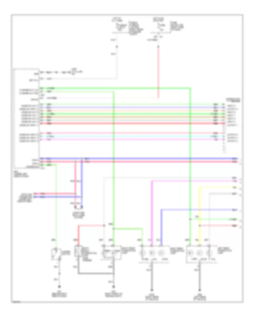
Computer Data Lines Wiring Diagram for Nissan Xterra Off Road 2005
List of elements for Computer Data Lines Wiring Diagram for Nissan Xterra Off Road 2005:
- (behind left side of dash) (pre-wiring) satellite radio tuner
- (behind right side of dash) m61
- (right rear of engine compt) engine control module (ecm)
- (under console box) air bag diagnosis sensor unit
- A/t assembly
- Abs actuator & electric unit (control unit) (at left rear corner of engine compt)
- Abs/tcs/vdc control unit
- Acc
- Ant sig
- Audio unit
- Body control module (bcm) (under left side of dash)
- Can-h
- Can-l
- Can2-h
- Can2-l
- Combination meter
- Cpu
- Data link connector (under left side of dash)
- Diag-k
- Differential lock control unit
- E122
- E125
- E16
- Earth
- F502
- Fuse 12 10a
- Fuse 19 10a
- Fuse 4 10a
- Fuse block (j/b) (right side of dash)
- Hot at all times
- Hot in on or acc
- Hot in on or start
- Ipdm e/r (right rear of engine compt)
- K-line
- M152
- M18
- M35
- M42
- M70
- Nats antenna amplifier (behind center of dash)
- Nca
- Pnk
- Rx, tx
- Rxd
- Steering angle sensor (below left side of dash, near steering column)
- Tcm
- Transfer control unit (behind left side of dash)
- Txd
- Unified meter control unit
- Yaw rate/side/ decel g sensor (under rear of center console)
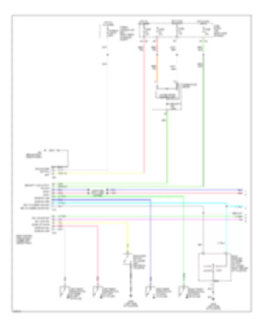
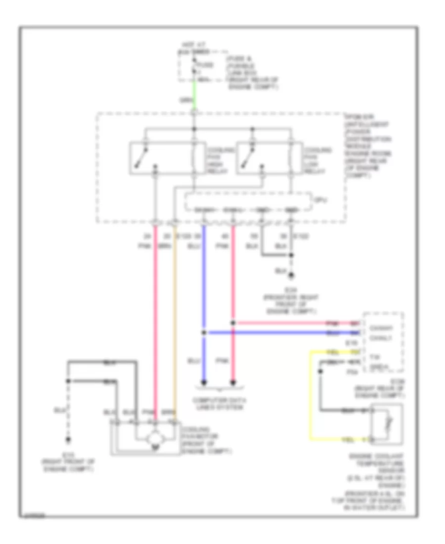
COOLING FAN
Cooling Fan Wiring Diagram for Nissan Xterra Off Road 2005
List of elements for Cooling Fan Wiring Diagram for Nissan Xterra Off Road 2005:
- (frontier 4.0l: on top front of engine, in water outlet)
- Can-h
- Can-h1
- Can-l
- Can-l1
- Computer data lines system
- Cooling fan high relay
- Cooling fan low relay
- Cooling fan motor (front of engine compt)
- Cpu
- E120
- E122
- E15 (right front of engine compt)
- E16
- E24 (frontier: right front of engine compt)
- Ecm (right rear of engine compt)
- Engine coolant temperature sensor (2.5l: at rear of) engine)
- F54
- Fuse & fusible link box (right rear of engine compt)
- Fuse j 40a
- Gnd
- Gnd-a
- Hot at all times
- Ipdm e/r (intelligent power distribution module engine room) (right rear of engine compt)
- Pnk
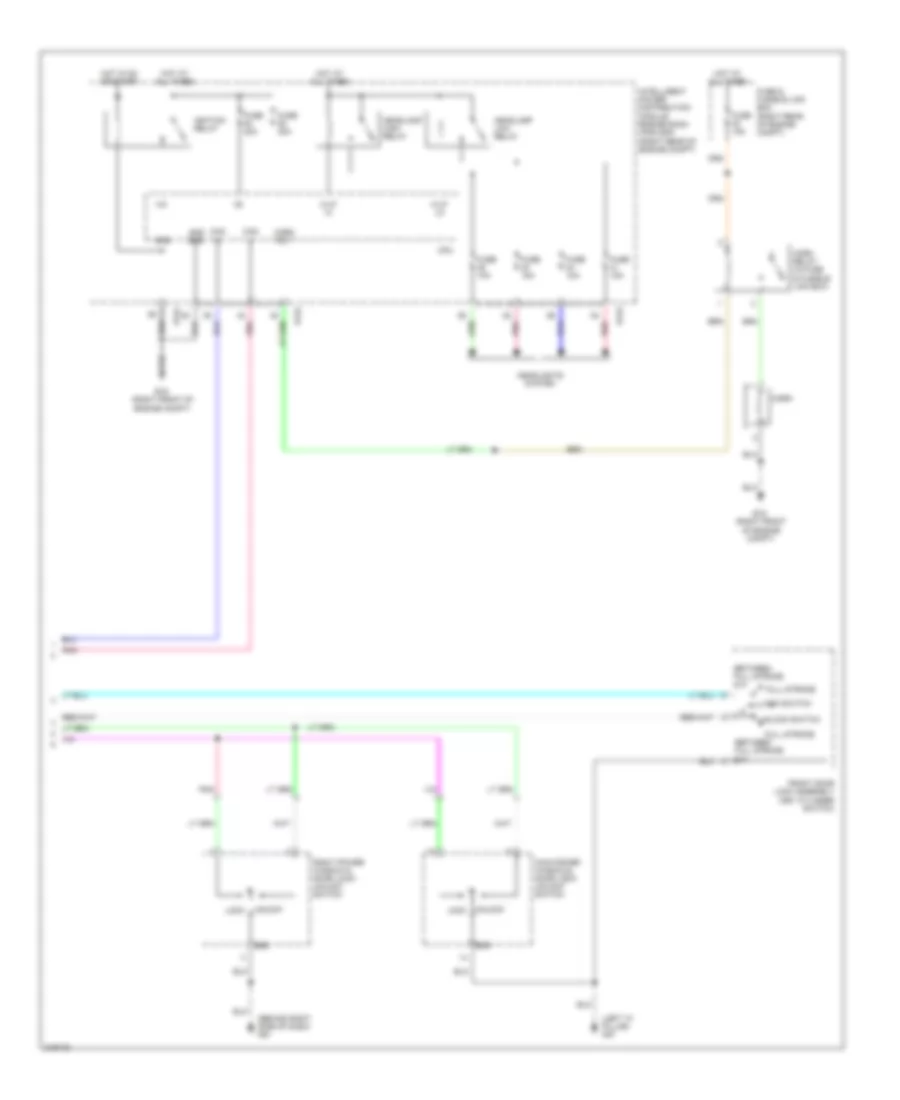
CRUISE CONTROL
Cruise Control Wiring Diagram for Nissan Xterra Off Road 2005
List of elements for Cruise Control Wiring Diagram for Nissan Xterra Off Road 2005:
- (frontier: on bracket, above brake pedal)
- (left side of engine compt) e9
- (xterra a/t: on bracket, above brake pedal)
- 1q e160
- A/t
- Accel/ resume switch
- Ascd brake switch (on bracket, above brake pedal)
- Ascd clutch switch (on bracket, above clutch pedal)
- Ascd steering switch
- Ascdsw
- Avcc2
- Bncsw
- Brake sw
- Can-h1
- Can-l1
- Cancel switch
- Close
- Coast/ set switch
- Combination meter
- Combination switch (spiral cable)
- Computer data lines system
- Cruise ind
- E16
- E9 (left side of engine compt)
- Ecm (right rear of engine compt)
- Electric throttle control actuator (on throttle body)
- F54
- Fuse 12 10a
- Fuse 14 10a
- Fuse 19 10a
- Fuse 20 10a
- Fuse block (j/b) (right side side of dash)
- Gnd-a
- Gnd-a2
- Ground
- Hot at all times
- Hot in on or start
- M/t
- M102
- M30
- M61 (behind right side of dash)
- Motor 1
- Motor 2
- Nca
- On/off switch
- Open
- Pnk
- Red
- Sensor 1
- Sensor 2
- Set
- Stoplight switch
- Tps1
- Tps2
- Unified meter control unit (w/odo/ trip meter)
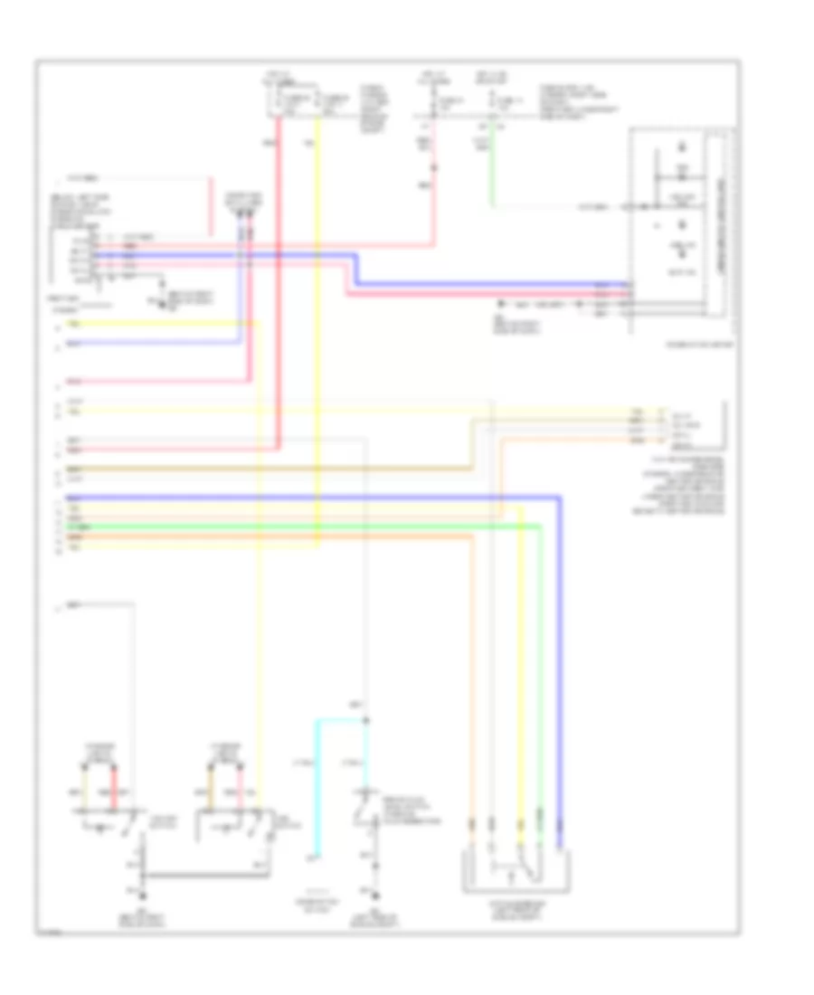
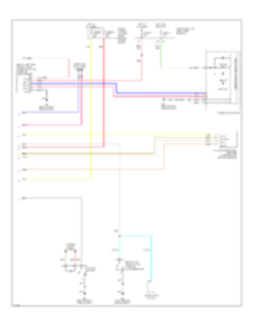
DEFOGGERS
Defoggers Wiring Diagram for Nissan Xterra Off Road 2005
List of elements for Defoggers Wiring Diagram for Nissan Xterra Off Road 2005:
- 15p
- B211 (frontier)
- Bat (f/l)
- Body control module (bcm) (frontier: under center of dash) (xterra: under left side of dash)
- Can-h
- Can-l
- Computer data lines system
- Cpu
- D603 (xterra) (right side of tailgate (defogger))
- Door mirror defogger
- E120
- E122
- E124
- E15 (right front of engine compt)
- Front air control
- Fuse & fusible link box (right rear of engine compt)
- Fuse 10a
- Fuse 15a
- Fuse block (j/b) (frontier: under right side of dash) (xterra: right side of dash)
- Fusible link g 50a
- Gnd
- Gnd pwr
- Heated mirror relay (if equipped)
- Hot at all times
- Hot in on
- Hot in on or start
- Ign
- Ign sw
- Ignition relay
- Ipdm e/r (right rear of engine compt)
- Left door mirror
- M18
- M20
- M57 (frontier: behind left side of dash) (xterra: left "a" pillar)
- M61 (behind right side of dash)
- Pnk
- Rear window defogger
- Rear window defogger relay
- Red
- Right door mirror
- Rr def
- Rr def req
- Rr def sw
ENGINE PERFORMANCE
4.0L
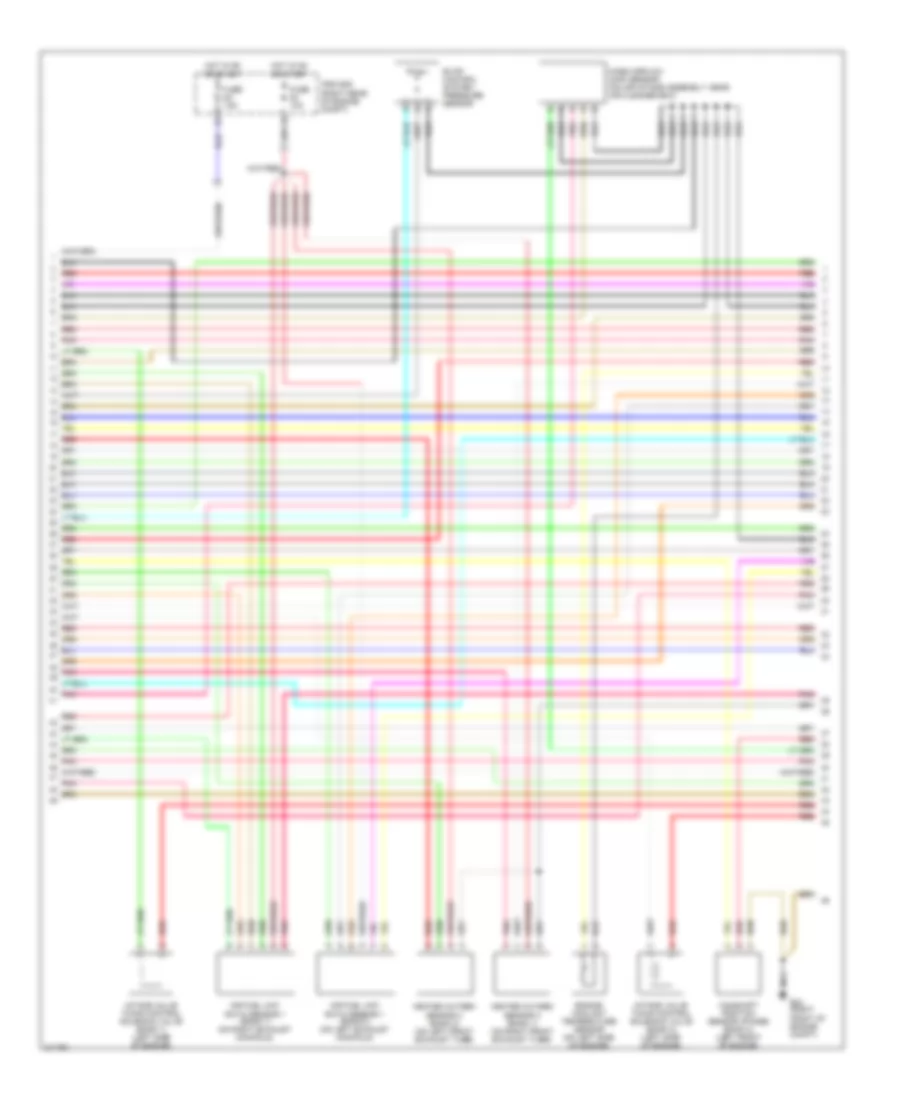
4.0L, Engine Performance Wiring Diagram (1 of 4) for Nissan Xterra Off Road 2005
List of elements for 4.0L, Engine Performance Wiring Diagram (1 of 4) for Nissan Xterra Off Road 2005:
- (left side of engine) f16
- (right front of engine compt) e24
- 15p
- A/f-ip1
- Af-h1
- Af-h2
- Af-un1
- Af-vm1
- Avcc
- Avcc2
- Battery current sensor (right front of engine compt)
- C-vtc (l)
- C-vtc (r)
- Combination meter
- Computer data lines system
- Condenser 1 (top of engine)
- Crankshaft position sensor (pos) (right rear of engine)
- E15 (right front of engine compt)
- E24 (right front of engine compt)
- Engine control module (right rear of engine compt)
- Evap
- Evap canister purge volume control solenoid valve (on left side of engine)
- Ftrps
- Fuel injector
- Fuse 10a
- Fuse block (j/b) (behind right side of dash)
- Gnd
- Hot in on or start
- Ignition coil 5 (w/ power transistor)
- Inj 1
- Inj 2
- Inj 3
- Inj 4
- Inj 5
- Inj 6
- Knk1
- Knk2
- Knock sensor (bank 1) (right side of engine)
- Knock sensor (bank 2) (left side of engine)
- M24
- Malfunction indicator lamp
- Motor1
- Motor2
- Nca
- Neutral
- O2hrl
- O2hrr
- O2srl
- Park/ neutral position switch (top of transmission)
- Pdpres
- Phase lh
- Phase rh
- Pnk
- Pos
- Ps pres
- Qa+
- Red
- Refrigerant pressure sensor (on a/c liquid tank)
- Spark plug
- Tps1
- Unified meter control unit
- V mot
- Vias
4.0L, Engine Performance Wiring Diagram (2 of 4) for Nissan Xterra Off Road 2005
List of elements for 4.0L, Engine Performance Wiring Diagram (2 of 4) for Nissan Xterra Off Road 2005:
- Accelerator pedal position sensor (at top of accelerator pedal assembly)
- E119
- E122
- E20
- E24 (right front of engine compt)
- Ecm relay
- Electric throttle control actuator (near throttle body)
- F16 (on left side of engine)
- F50
- Fuel pump relay
- Fuse 15a
- Fuse 20a
- Hot at all times
- Hot in on or start
- Ignition coil 1 (w/ power transistor)
- Ignition coil 2 (w/ power transistor)
- Ignition coil 3 (w/ power transistor)
- Ignition coil 4 (w/ power transistor)
- Ignition coil 6 (w/ power transistor)
- Ipdm e/r (right rear of engine compt)
- Nca
- Plug spark
- Pnk
- Red
- Sensor 1
- Sensor 2
- Spark plug
- Throttle control motor
- Throttle control motor relay
- Throttle position (tp) sensor 1
- Throttle position (tp) sensor 2
4.0L, Engine Performance Wiring Diagram (3 of 4) for Nissan Xterra Off Road 2005
List of elements for 4.0L, Engine Performance Wiring Diagram (3 of 4) for Nissan Xterra Off Road 2005:
- Air fuel (a/f) ratio sensor 1 (bank 1) (on right exhaust manifold)
- Air fuel (a/f) ratio sensor 1 (bank 2) (on left exhaust manifold)
- Camshaft position sensor (phase) (bank 2) (left front of engine)
- E24 (right front of engine compt)
- Engine coolant temperature sensor (on left side of engine)
- Evap control system pressure sensor
- Fuse 10a
- Fuse 15a
- Heated oxygen sensor 2 (bank 1) (on right front exhaust tube)
- Heated oxygen sensor 2 (bank 2) (on left front exhaust tube)
- Hot in on or start
- Intake valve timing control solenoid valve (bank 1) (left side of engine)
- Intake valve timing control solenoid valve (bank 2) (left side of engine)
- Ipdm e/r (right rear of engine compt)
- Mass airflow (maf) sensor (on air intake assembly, near air cleaner box)
- Nca
- Pnk
- Red
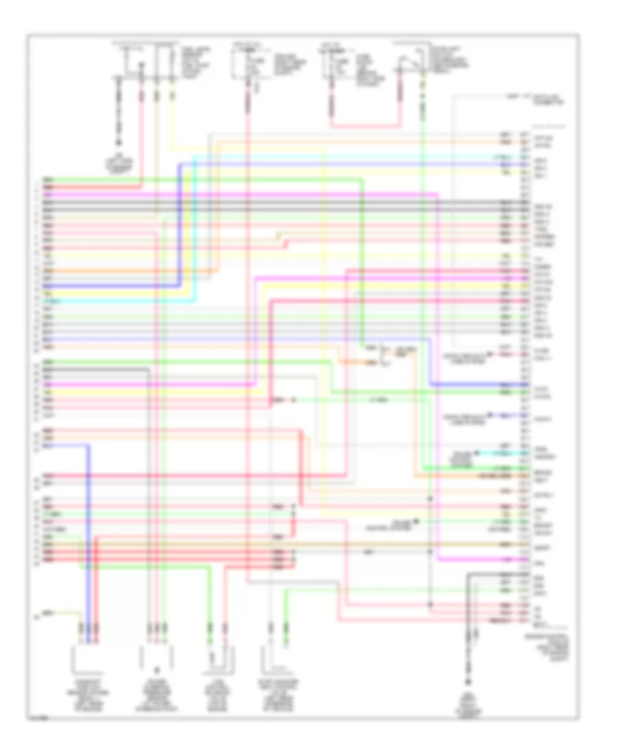
4.0L, Engine Performance Wiring Diagram (4 of 4) for Nissan Xterra Off Road 2005
List of elements for 4.0L, Engine Performance Wiring Diagram (4 of 4) for Nissan Xterra Off Road 2005:
- A/f-ia1
- A/f-ia2
- A/f-ip2
- A/f-un2
- A/f-vm2
- A/t
- Aps1
- Aps2
- Ascdsw
- Avcc
- Avcc2
- Batt
- Bncsw
- Brake
- Camshaft position sensor (phase) (bank 1) (left rear of engine)
- Can l1
- Can-h1
- Cdcv
- Cir sen
- Computer data lines system
- Cruise control system
- Data link connector
- E121
- E24 (right front of engine compt)
- E9 (left side of engine compt)
- Engine control module (right rear of engine compt)
- Evap canister vent control valve (left rear underside of vehicle)
- Fpr
- Fuel level sensor unit & fuel pump (in fuel tank)
- Fuse 10a
- Fuse 20a
- Fuse block (j/b) (behind right side of dash)
- Gnd
- Gnd 02
- Gnd a
- Gnd a2
- Hot at all times
- Ign 1
- Ign 2
- Ign 3
- Ign 4
- Ign 5
- Ign 6
- Ign sw
- Ipdm e/r (right rear of engine compt)
- Kline
- M/t
- Motrly
- Nca
- Neut
- O2srr
- Orn
- Pdpres
- Pnk
- Power steering pressure sensor (at power steering pump)
- Red
- Ssoff
- Stoplight switch (on bracket, above brake pedal)
- Tps2
- Vias control solenoid valve (top of engine)
EXTERIOR LIGHTS
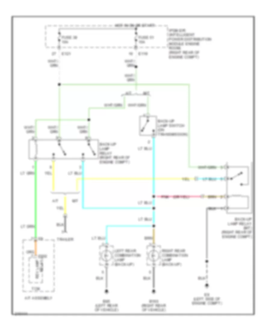
Back-up Lamps Wiring Diagram for Nissan Xterra Off Road 2005
List of elements for Back-up Lamps Wiring Diagram for Nissan Xterra Off Road 2005:
- A/t
- A/t assembly
- B160 (right rear of vehicle)
- B85 (left rear of vehicle)
- Back-up lamp relay (m/t) (right rear of engine compt)
- Back-up lamp relay (right rear of engine compt)
- Back-up lamp switch (on transmission)
- E119
- E121
- E9 (left side of engine compt)
- F502
- Fuse 38 10a
- Fuse 51 10a
- Hot in on or start
- Ipdm e/r (intelligent power distribution module engine room) (right rear of engine compt)
- Left rear combination lamp (back-up)
- M/t
- Pnk
- Rev lamp relay
- Right rear combination lamp (back-up)
- Tcm
- Trailer
Exterior Lamps Wiring Diagram (1 of 2) for Nissan Xterra Off Road 2005
List of elements for Exterior Lamps Wiring Diagram (1 of 2) for Nissan Xterra Off Road 2005:
- (left "a" pillar) m57
- (under left side of dash)
- 15p m4
- B160 (right rear of vehicle)
- B85 (left rear of vehicle)
- Bat (f/l)
- Bcm (under left side of dash)
- Can-h
- Can-l
- Combi sw input 1
- Combi sw input 2
- Combi sw input 3
- Combi sw input 4
- Combi sw input 5
- Combi sw out 1
- Combi sw out 2
- Combi sw out 3
- Combi sw out 4
- Combi sw out 5
- Combination switch
- Computer data lines system
- Data link connector
- E15 (right front of engine compt)
- Flasher out (lh)
- Flasher out (rh)
- Fuse & fusible link box (right rear of engine compt)
- Fuse 10a
- Fuse block (j/b) (right side of dash)
- Fusible link g 50a
- Gnd
- Hazard sw
- Hazard switch
- Hot at all times
- Hot in on or start
- Ign sw
- Input 1
- Input 2
- Input 3
- Input 4
- Input 5
- Left rear combination lamp
- M18
- M20
- M61 (behind right side of dash)
- Output 1
- Output 2
- Output 3
- Output 4
- Output 5
- Park
- Pnk
- Red
- Right front combination lamp
- Right front combination lamp (side marker)
- Right rear combination lamp
- Stop
- Tail
- Turn
Exterior Lamps Wiring Diagram (2 of 2) for Nissan Xterra Off Road 2005
List of elements for Exterior Lamps Wiring Diagram (2 of 2) for Nissan Xterra Off Road 2005:
- (at left rear corner of engine compt) abs actuator & electric unit (control unit)
- (right rear of engine compt) (w/ hill descent control & hill start assist) stop lamp relay
- +ig
- 8p m4
- 8q e160
- Abs/tcs/vdc control unit
- Can-h
- Can-l
- Combination meter
- Cpu
- D406 (left side of tailgate)
- E121
- E122
- E123
- E124
- E15 (right front of engine compt)
- Electric brake (pre-wiring) (behind left side of dash)
- Fuse 10a
- Fuse 37 10a
- Fuse 53 20a
- Fuse block (j/b) (right side of dash)
- Gnd (power)
- Gnd (signal)
- High mounted stop lamp
- Hot at all times
- Hot in on or start
- Ignition relay
- Interior lights system
- Ipdm e/r (intelligent power distribution module engine room) (right rear of engine compt)
- Left front combination lamp
- Left front combination lamp (side marker)
- Left turn ind
- License plate lamp
- M57 (left "a" pillar)
- Park
- Pnk
- Red
- Right turn ind
- Stop lamp sw
- Stop lamp sw on
- Stop lamp switch (a/t) (on bracket, above brake pedal)
- Tail lamp relay
- Tail/l rly
- Turn
- Unified meter control unit
Trailer Tow Wiring Diagram for Nissan Xterra Off Road 2005
List of elements for Trailer Tow Wiring Diagram for Nissan Xterra Off Road 2005:
- (behind left side of dash) electric brake (pre-wiring)
- (behind right side of dash) m61
- (left "a" pillar)
- (under left side of dash)
- +ig
- 15p m4
- Back-up lamps circuit
- Bat (f/l)
- Bcm (under left side of dash)
- Can-h
- Can-l
- Combi sw input 1
- Combi sw input 2
- Combi sw input 3
- Combi sw input 4
- Combi sw input 5
- Combi sw out 1
- Combi sw out 2
- Combi sw out 3
- Combi sw out 4
- Combi sw out 5
- Combination switch
- Computer data lines system
- Cpu
- Data link connector
- E121
- E122
- E124
- E15 (right front of engine compt)
- E15 (right side of engine compt)
- Exterior lights system
- Fuse & fusible link box (right rear of engine compt)
- Fuse 10a
- Fuse 20a
- Fuse 37 10a
- Fuse block (j/b) (right side of dash)
- Fusible link g 50a
- Fusible link h 30a
- Fusible link m 30a
- Gnd
- Gnd (power)
- Gnd (signal)
- Hot at all times
- Hot in on or start
- Ign sw
- Ignition relay
- Input 1
- Input 2
- Input 3
- Input 4
- Input 5
- Interior lights system
- Ipdm e/r (intelligent power distribution module engine room) (right rear of engine compt)
- M18
- M19
- M20
- M57
- Output 1
- Output 2
- Output 3
- Output 4
- Output 5
- Pnk
- Red
- Tail lamp relay
- Tail/l rly
- Trailer
- Trailer lh flash
- Trailer rh flash
- Trailer tow relay 1 (right side of engine compt)
- Trailer tow relay 2 (right side of engine compt)
GROUND DISTRIBUTION
Ground Distribution Wiring Diagram (1 of 2) for Nissan Xterra Off Road 2005
List of elements for Ground Distribution Wiring Diagram (1 of 2) for Nissan Xterra Off Road 2005:
- A/t assembly
- B19 (left rear of vehicle)
- B7 (under driver's seat)
- Bcm, data link connector, combination meter, combination switch, front room/map lamp assembly, door mirror (left), main power window & door lock/unlock switch, front door lock assembly
- Camshaft position sensor (phase) (bank 2), electric throttle control actuator, ecm, camshaft position sensor (phase) (bank 1), atp switch, transfer control device, wait detection switch, 4lo switch
- Differential lock control unit, ecm, front blower motor relay, ipdm e/r, transfer shut off relay 1, clutch interlock cancel relay 1, clutch interlock cancel relay 2, crankshaft position sensor
- E15 (right front of engine compt)
- E24 (right front of engine compt)
- E9 (left side of engine compt)
- F10 (top left side of engine)
- F16 (top left of engine)
- Front passenger air bag off indicator, nats antenna amplifier, combination meter, air bag diagnosis sensor, steering angle sensor, front air control, front blower switch, hazard switch, transfer control unit, vdc off switch, hdc switch, a/t device, door mirror remote control switch, clutch interlock cancel switch, console power socket
- Fuse bloc (j/b), lower front power socket, upper front power socket, electric brake, power window & door lock/unlock switch (right), door mirror (right)
- Ignition coil 2 (w/ power transistor), ignition coil 4 (w/ power transistor), ignition coil 6 (w/ power transistor), condenser 1, ignition coil 1 (w/ power transistor), ignition coil 3 (w/ power transistor), ignition coil 5 (w/ power transistor)
- Knock sensor (bank 1) shield, knock sensor (bank 2) shield, differential lock position switch, license plate lamp
- Left front combination lamp (headlight), left front combination lamp (parking/turn signal, left front fog lamp, right front combination lamp (side marker), cooling fan motor, park/neutral position switch (m/t)
- Left front combination lamp (side marker), brake fluid level switch, front wiper motor, right front fog light, daytime light relay 2, daytime light relay 1, washer fluid level switch, right front combination lamp (headlamp)
- Left seat belt buckle switch, left vanity lamp, right vanity lamp, left rear power window switch
- M57 (left "a" pillar)
- M61 (behind right side of dash)
- M79 (behind right side of dash)
- Right front combination lamp (parking/turn signal), horn, trailer tow relay 1, trailer tow relay 2, fuel level sensor unit & fuel pump, trailer
Ground Distribution Wiring Diagram (2 of 2) for Nissan Xterra Off Road 2005
List of elements for Ground Distribution Wiring Diagram (2 of 2) for Nissan Xterra Off Road 2005:
- Abs actuator & electric unit (control unit)
- B112 (right rocker panel)
- B117 (under front passenger's seat)
- B132 (right rear of vehicle)
- B160 (right rear of vehicle)
- B5 (left rocker panel)
- B85 (left rear of vehicle)
- Crash zone sensor (shield wire)
- D406 (left side of tailgate)
- D603 (right side of tailgate)
- D652 (left side of tailgate)
- E126 (left side of engine compt)
- E14 (left side of engine compt)
- High mounted stop lamp, back door switch, back door key cylinder switch, rear wiper motor
- Left rear combination lamp
- Left side air bag satellite sensor (shield wire)
- Rear window defogger
- Right rear combination lamp
- Right seat belt buckle switch, occupant classification system control unit, audio amplifier, right rear power window switch, right rear combination lamp
- Right side air bag satellite sensor (shield wire)
HEADLIGHTS
Headlights Wiring Diagram, with DRL for Nissan Xterra Off Road 2005
List of elements for Headlights Wiring Diagram, with DRL for Nissan Xterra Off Road 2005:
- (right front of engine compt) e15
- +ig
- Bat (f/l)
- Body control module (bcm) (under left side of dash)
- Brake indicator
- Can-h
- Can-l
- Charge indicator
- Comb sw in 1
- Comb sw in 2
- Comb sw in 3
- Comb sw in 4
- Comb sw in 5
- Comb sw out 1
- Comb sw out 2
- Comb sw out 3
- Comb sw out 4
- Comb sw out 5
- Combination meter
- Combination switch
- Computer data lines system
- Cpu
- Daytime light relay 1 (right rear of engine compt)
- Daytime light relay 2 (right rear of engine compt)
- Dtrl
- E119
- E122
- E123
- E124
- E15 (right front of engine compt)
- Fr fog
- Front fog lamp relay
- Fuse & fusible link box (right rear of engine compt)
- Fuse 10a
- Fuse 15a
- Fuse 20a
- Fuse block (j/b) (right side of dash)
- Fusible link g 50a
- Gnd
- H/lp hi
- H/lp lo
- Headlamp high relay
- Headlamp low relay
- High beam
- High beam indicator
- Hot at all times
- Hot in on or start
- Ignition relay
- Input 1
- Input 2
- Input 3
- Input 4
- Input 5
- Ipdm e/r (right rear of engine compt)
- Left front combination lamp
- Left front fog lamp
- Low beam
- M18
- M20
- M24
- M61 (behind right side of dash)
- M61 (behind right side of of dash)
- Output 1
- Output 2
- Output 3
- Output 4
- Output 5
- Parking brake switch (on base of parking brake lever)
- Pnk
- Pwr gnd
- Red
- Right front combination lamp
- Right front fog lamp
- Sig gnd
- Starting/charging system
- Unified meter control unit
Headlights Wiring Diagram, without DRL for Nissan Xterra Off Road 2005
List of elements for Headlights Wiring Diagram, without DRL for Nissan Xterra Off Road 2005:
- +ig
- Bat (f/l)
- Body control module (bcm) (under left side of dash)
- Can-h
- Can-l
- Comb sw in 1
- Comb sw in 2
- Comb sw in 3
- Comb sw in 4
- Comb sw in 5
- Comb sw out 1
- Comb sw out 2
- Comb sw out 3
- Comb sw out 4
- Comb sw out 5
- Combination meter
- Combination switch
- Computer data lines system
- Cpu
- E122
- E123
- E124
- E15 (right front of engine compt)
- Fr fog
- Front fog lamp relay
- Fuse & fusible link box (right rear of engine compt)
- Fuse 10a
- Fuse 15a
- Fuse 20a
- Fuse block (j/b) (right side of dash)
- Fusible link g 50a
- Gnd
- H/lp hi
- H/lp lo
- Headlamp high relay
- Headlamp low relay
- High beam
- High beam indicator
- Hot at all times
- Hot in on or start
- Ignition relay
- Input 1
- Input 2
- Input 3
- Input 4
- Input 5
- Ipdm e/r (right rear of engine compt)
- Left front combination lamp
- Left front fog lamp
- Low beam
- M18
- M20
- M24
- M61 (behind right side of dash)
- M61 (behind right side of of dash)
- Output 1
- Output 2
- Output 3
- Output 4
- Output 5
- Pnk
- Pwr gnd
- Red
- Right front combination lamp
- Right front fog lamp
- Sig gnd
- Unified meter control unit
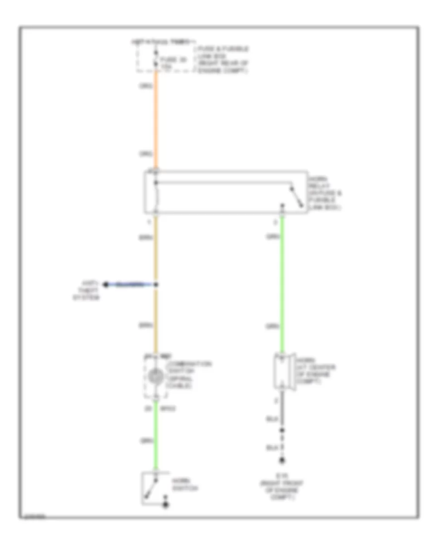
HORN
Horn Wiring Diagram for Nissan Xterra Off Road 2005
List of elements for Horn Wiring Diagram for Nissan Xterra Off Road 2005:
- Anti- theft system
- Combination switch (spiral cable)
- E15 (right front of engine compt)
- Fuse & fusible link box (right rear of engine compt)
- Fuse 30 15a
- Horn (at center of engine compt)
- Horn relay (in fuse & fusible link box)
- Horn switch
- Hot at all times
- M102
- M30
INSTRUMENT CLUSTER
Instrument Cluster Wiring Diagram for Nissan Xterra Off Road 2005
List of elements for Instrument Cluster Wiring Diagram for Nissan Xterra Off Road 2005:
- (a/t) atp ind
- (a/t) o/d off ind
- (if equipped) vdc off ind
- (w/ abls or vdc) slip ind
- (w/ ascd) cruise ind
- (w/ ascd) set ind
- (w/ electronic locking rear differental) diff lock
- 2wd ind (w/ 4wd)
- 4lo ind (w/ 4wd)
- 4wd fail ind (w/ 4wd)
- A/t check ind
- Abs ind
- Air bag ind
- Back door switch (at lower left center of tailgate)
- Body control module (under left side of dash)
- Brake fluid level switch (in brake fluid reservoir)
- Brake ind
- Buzzer
- Can h
- Can l
- Charge ind
- Combination meter
- Computer data lines system
- D406 (left side of tailgate)
- Door ind
- Dr sw
- Dr sw
- E15 (right front of engine compt)
- Fuel gauge
- Fuel level sensor & fuel pump (in fuel tank)
- Fuse 10a
- Fuse block (j/b) (right side of dash)
- Gnd
- Hdc ind (if equipped)
- High beam ind
- Hot at all times
- Hot in on or start
- Interior lights system
- Left front door switch (at base of left "b" pillar)
- Left rear door switch (at left "c" pillar)
- Left turn ind
- Lock ind (w/ 4wd)
- Low fuel ind
- M18
- M19
- M61 (behind right side of dash)
- Malfunction ind lamp
- Meter illum
- Oil pressure gauge
- Oil pressure ind
- Oil pressure sensor (lower right side of engine)
- Parking brake switch (on base of parking brake lever)
- Pnk
- Red
- Right front door switch (at right "b" pillar)
- Right rear door switch (at right "c" pillar)
- Right turn ind
- Seat belt ind
- Security ind
- Speedometer
- Starting/charging system
- Tachometer
- Tire pressure ind
- Transmissions system
- Unified meter control unit (w/ odometer/trip meter)
- Vcc
- Volt gauge
- Vout
- W/ 4wd
- Warning system
- Washer ind
- Water temp gauge
- Wiper/washer system
INTERIOR LIGHTS
Courtesy Lamps Wiring Diagram, with Power Door Locks for Nissan Xterra Off Road 2005
List of elements for Courtesy Lamps Wiring Diagram, with Power Door Locks for Nissan Xterra Off Road 2005:
- 15p
- B7 (under driver's seat)
- Back door sw
- Back door switch (at lower left center of tailgate)
- Bat (f/l)
- Bat (fuse)
- Bat saver
- Body control module (bcm) (under left side of dash)
- Can-h
- Can-l
- Cargo lamp
- Computer data lines system
- D406 (left side of tailgate)
- Door
- Door sw (as)
- Door sw (dr)
- Door sw (rl)
- Door sw (rr)
- Front room/map lamp assembly
- Fuse 10a
- Fuse & fusible link box (right rear of engine compartment)
- Fuse block (j/b) (right side of dash)
- Fusible link g 50a
- Gnd
- Hot at all times
- Hot in on or start
- Ign key ill
- Ign sw
- Ignition keyhole illumination
- Key switch
- Left front door switch (at base of left "b" pillar)
- Left rear door switch (at left "c" pillar)
- Left vanity lamp (w/ vanity lamps)
- Luggage lamp out
- M18
- M19
- M20
- M57 (left "a" pillar)
- Off
- Pnk
- Right front door switch (at right "b" pillar)
- Right rear door switch
- Right vanity lamp (w/ vanity lamps)
- Room lamp
- Room lamp 2nd row
Courtesy Lamps Wiring Diagram, without Power Door Locks for Nissan Xterra Off Road 2005
List of elements for Courtesy Lamps Wiring Diagram, without Power Door Locks for Nissan Xterra Off Road 2005:
- Back door switch (at lower left center of tailgate)
- Cargo lamp
- D406 (left side of tailgate)
- Diode 6 (behind left side of dash)
- Diode 7 (behind left side of dash)
- Door
- Door door door
- Front room/map lamp assembly
- Fuse 10a
- Fuse block (j/b) (right side of dash)
- Hot at all times
- Ignition keyhole illumination
- Left front door switch (at base of left "b" pillar)
- Left rear door switch (at left "c" pillar)
- M57 (left "a" pillar)
- Off
- Off off off
- On on on
- Red
- Right front door switch (at right "b" pillar)
- Right rear door swicth
- Room lamp 2nd row
Instrument Illumination Wiring Diagram for Nissan Xterra Off Road 2005
List of elements for Instrument Illumination Wiring Diagram for Nissan Xterra Off Road 2005:
- (left "a" pillar) m57
- +ig
- 15p
- 4wd shift switch (if equipped)
- A/t device (near base of a/t selector lever)
- Audio unit
- Bat (f/l)
- Body control module (bcm) (under left side of dash)
- Can-h
- Can-l
- Clutch interlock cancel switch (if equipped) (on bracket, above clutch pedal)
- Comb sw in 1
- Comb sw in 2
- Comb sw in 3
- Comb sw in 4
- Comb sw in 5
- Comb sw out 1
- Comb sw out 2
- Comb sw out 3
- Comb sw out 4
- Comb sw out 5
- Combination meter
- Combination switch
- Control
- Cpu
- Data link connector (under left side of dash)
- Differential lock switch (if equipped)
- Door mirror remote
- E122
- E124
- E15 (right front of engine compartment)
- Electric brake (pre-wiring) (w/ trailer tow 7 pin)
- Exterior lights system
- Front air control
- Fuse & fusible link box (right rear of engine compartment)
- Fuse 10a
- Fuse 20a
- Fuse block (j/b) (right side of dash)
- Fusible link g 50a
- Gnd
- Gnd (pwr)
- Gnd (sig)
- Hazard switch
- Hdc switch (w/ hill descent control and hill start assist)
- Hot at all times
- Hot in on or start
- Ign sw
- Ignition
- Ill
- Input 1
- Input 2
- Input 3
- Input 4
- Input 5
- Ipdm e/r (right rear of engine compartment)
- M18
- M20
- M57 (left "a" pillar)
- Meter illumi- nation
- Output 1
- Output 2
- Output 3
- Output 4
- Output 5
- Pnk
- Red
- Relay
- Switch (if equipped)
- Tail lamp relay
- Tail/l rly
- Unified meter control unit
- Vdc off switch (w/ vdc)
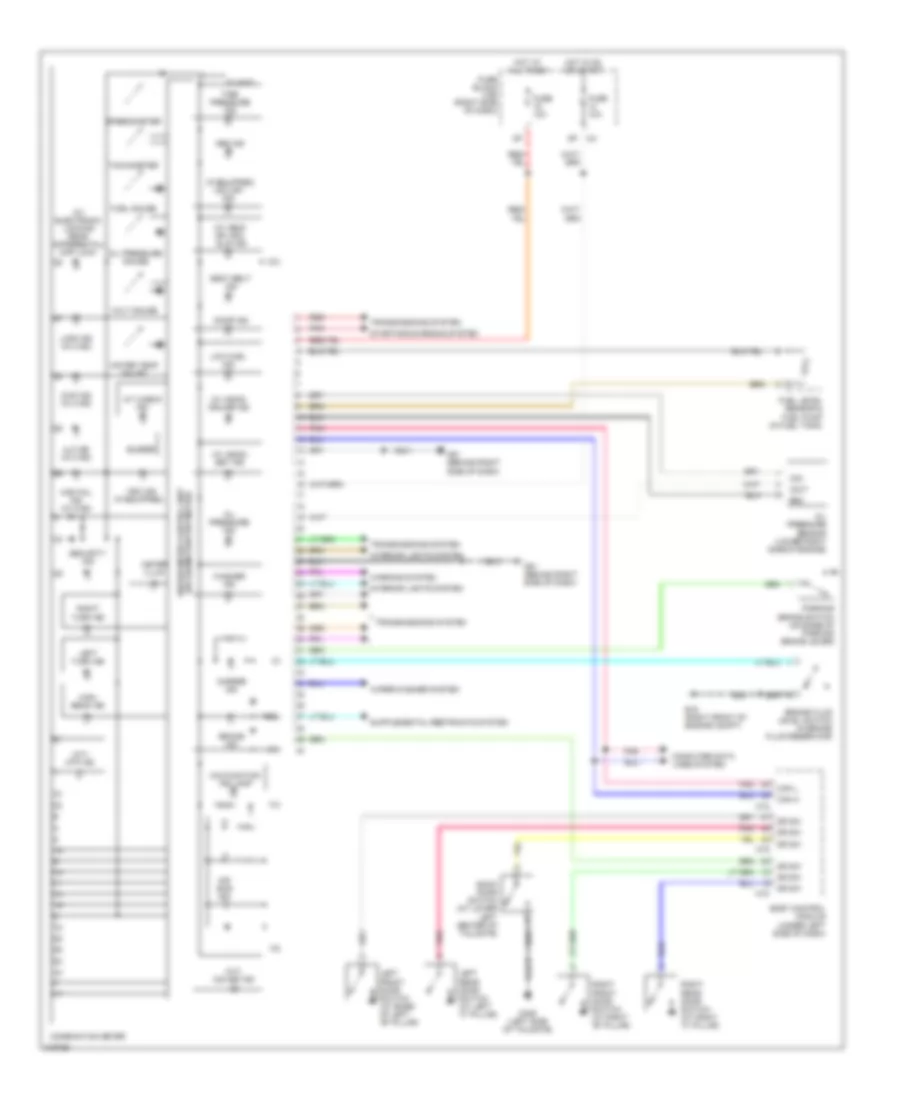
POWER DISTRIBUTION
Power Distribution Wiring Diagram (1 of 2) for Nissan Xterra Off Road 2005
List of elements for Power Distribution Wiring Diagram (1 of 2) for Nissan Xterra Off Road 2005:
- (behind right side of dash)
- (right rear of engine compt) fuse & fusible link box
- (under front passenger's seat)
- A/c relay
- Air conditioning system
- Anti-lock brakes system
- Anti-theft, starting/charging, horn system
- B117
- Battery
- Computer data lines system
- Cpu
- Defogger, cooling fans systems
- Door locks, interior lights system
- E118
- E119
- E121
- E122
- E123
- E124
- E128
- E129
- E202
- E30
- Ecm relay
- Engine controls system
- Engine controls, anti-theft systems
- Exterior lights system
- F39
- Front fog lamp relay
- Front wiper hi relay
- Front wiper relay
- Fuse 10a
- Fuse 15a
- Fuse 20a
- Fuse 30a
- Fusible link a 140a
- Fusible link b 60a
- Fusible link box (battery) (right rear of engine compt)
- Fusible link c 80a
- Fusible link d 80a
- Fusible link e 100a
- Fusible link f 80a
- Fusible link g 50a
- Fusible link h 30a
- Fusible link i 40a
- Fusible link j 40a
- Fusible link m 30a
- Fusible link n 30a
- Head- lights system
- Headlights system
- Heated mirror relay
- Intelligent power distribution module engine room (ipdm e/r)
- Interior lights, exterior lights systems
- Interior, exterior lights system
- Lower front power socket
- M79
- Nca
- Pnk
- Rear cargo power socket
- Red
- Sound system
- Starting/ charging system
- Tail lamp relay
- Throttle control motor relay
- To fuse (diagram 2 of 2)
- To fuse 22 (diagram 2 of 2)
- To fuse 46 (diagram 2 of 2)
- To fuse 48 (diagram 2 of 2)
- To headlight hi relay (diagram 2 of 2)
- To ignition relay (diagram 2 of 2)
- To ignition switch (diagram 2 of 2)
- Transmission system
- Wiper/ washer system
Power Distribution Wiring Diagram (2 of 2) for Nissan Xterra Off Road 2005
List of elements for Power Distribution Wiring Diagram (2 of 2) for Nissan Xterra Off Road 2005:
- (behind right (behind right side of dash) side of dash)
- (behind side of dash) fuse block (j/b)
- (diagram 1 of 2)
- 10p
- 11p
- 12p
- 13p
- 14p
- 15p
- Acc
- Accessory relay
- Air conditioning, defogger systems
- Anti-lock brakes system
- Console power socket
- Cpu
- Defogger system
- Door locks, anti-theft, warning, engine cntrls, defogger, interior lts, exterior lts, wiper/washer systems
- E119
- E121
- E122
- E123
- E124
- E24 (left side of engine compt)
- Engine control system
- Engine controls system
- From a/c relay (diagram 1 of 2)
- From ecm relay (diagram 1 of 2)
- From front wiper hi relay (diagram 1 of 2)
- From fuse 43 (diagram 1 of 2)
- From fuse 52 (diagram 1 of 2)
- From fusible link b (diagram 1 of 2)
- From fusible link j b
- From ignition switch (diagram 2 of 2)
- Fuel pump relay
- Fuse 10a
- Fuse 15a
- Headlight high relay
- Headlight low relay
- Headlights, anti-theft system
- Ig2 red
- Ignition relay
- Ignition switch
- Intelligent power distribution module engine room (ipdm e/r)
- Interior lights, door locks, anti-theft systems
- M61
- M79 (behind right side of dash)
- M79 m79
- Mirrors system
- Off
- Pnk
- Rear window defogger relay
- Red
- Seats system
- Sound, power windows, door locks, anti-theft systems
- Start
- Starting/ charging system
- Starting/ charging, transmissions systems
- To ignition relay (diagram 2 of 2)
- Transmission system
- Transmission, anti-theft, instrument cluster, headlights, interior lights, exterior lights, air conditioning systems
- Transmission, electronic suspension systems
- Transmission, engine control systems
- Transmissions systems
- Transmissions, exterior lights systems
- Upper front power socket
- Wiper/washer system
POWER DOOR LOCKS
Door Lock & Keyless Entry Wiring Diagram (1 of 2) for Nissan Xterra Off Road 2005
List of elements for Door Lock & Keyless Entry Wiring Diagram (1 of 2) for Nissan Xterra Off Road 2005:
- Acc sw
- Back door sw
- Back door switch (lower left center of tailgate)
- Bat (f/l)
- Bat (fuse)
- Bat saver output
- Body control module (bcm) (under left side of dash)
- Can-h
- Can-l
- Closed
- Cylinder lock sw
- Cylinder unlock sw
- D406 (left side of tailgate)
- Data link connector
- Door lock output (all)
- Door sw (as)
- Door sw (dr)
- Door sw (rl)
- Door sw (rr)
- Door unlock output
- Door unlock output (dr)
- Exterior lights system
- Flasher output (left)
- Flasher output (right)
- Fuse & fusible link box (right rear of engine compt)
- Fuse 10a
- Fuse block (j/b) (behind right side of dash)
- Fusible link g 50a
- Gnd (power)
- Hot at all times
- Hot in acc or on
- Ign sw
- Inserted
- Interior lights system
- Key cylinder lock sw
- Key cylinder unlock sw
- Key sw
- Key switch & key lock solenoid (on steering column)
- Left front door switch (at base of left "b" pillar)
- Left rear door switch (at left "c" pillar)
- M18
- M19
- M20
- M3 4n
- M4 15p
- M57 (left "a" pillar)
- Open
- Pnk
- Remote keyless entry receiver (behind right side of dash)
- Removed
- Right front door switch (at right "b" pillar)
- Right rear door switch (at right "c" pillar)
- Room lamp output
- Sig gnd
- Signal
- Signal gnd
- Signal pwr
Door Lock & Keyless Entry Wiring Diagram (2 of 2) for Nissan Xterra Off Road 2005
List of elements for Door Lock & Keyless Entry Wiring Diagram (2 of 2) for Nissan Xterra Off Road 2005:
- (left "a" pillar) m57
- (rear of left rear door) left rear door lock actuator
- (rear of right front door) right front door lock actuator
- (rear of right rear door) right rear door lock actuator
- +ig
- Back door key cylinder switch (in tailgate)
- Back door lock actuator (center of back door)
- Between full stroke & n
- Can h
- Can l
- Cpu
- D105
- D406 (left side of tailgate)
- E122
- E124
- E24 (left front of engine compt)
- E9 (left side of engine compt)
- Front door lock assembly (key cylinder switch) (rear of left front door)
- Fuse & fusible link box (right rear of engine compt)
- Fuse 15a
- Fuse 20a
- Gnd
- H/lp hi
- H/lp lo
- Headlights system
- Horn
- Horn relay (in fuse & fusible link box)
- Horn rly
- Horns system
- Hot at all times
- Hot in on and start
- Ignition relay
- Intelligent power distribution module engine room (ipdm e/r) (right rear of engine compt)
- Lock
- Lock switch full stroke
- M79 (behind right side of dash)
- Main power window & door lock/ unlock switch (on left front door)
- Pnk
- Right power window & door lock/ unlock switch (on right front door)
- Unlock
- Unlock switch full stroke
Door Lock Wiring Diagram (1 of 2) for Nissan Xterra Off Road 2005
List of elements for Door Lock Wiring Diagram (1 of 2) for Nissan Xterra Off Road 2005:
- 6t m60
- Acc sw
- Back door sw
- Back door switch (lower left center of tailgate)
- Bat (f/l)
- Bat (fuse)
- Body control module (bcm) (under left side of dash)
- Can-h
- Can-l
- Closed
- Computer data lines system
- Cylinder lock sw
- Cylinder unlock sw
- D406 (left side of tailgate)
- Data link connector
- Door lock output (all)
- Door sw (as)
- Door sw (dr)
- Door sw (rl)
- Door sw (rr)
- Door unlock output
- Door unlock output (dr)
- Fuse & fusible link box (right rear of engine compt)
- Fuse 10a
- Fuse block (j/b) (behind right side of dash)
- Fusible link g 50a
- Gnd (power)
- Hot at all times
- Hot in acc or on
- Inserted
- Key cylinder lock sw
- Key cylinder unlock sw
- Key sw
- Key switch & key lock solenoid (on steering column)
- Left front door switch (at base of left "b" pillar)
- Left rear door switch (at left "c" pillar)
- M18
- M19
- M20
- M3 4n
- M57 (left "a" pillar)
- Open
- Pnk
- Removed
- Right front door switch (at right "b" pillar)
- Right rear door switch (at right "c" pillar)
Door Lock Wiring Diagram (2 of 2) for Nissan Xterra Off Road 2005
List of elements for Door Lock Wiring Diagram (2 of 2) for Nissan Xterra Off Road 2005:
- (left "a" pillar) m57
- (rear of left rear door) left rear door lock actuator
- (rear of right front door) right front door lock actuator
- (rear of right rear door) right rear door lock actuator
- Back door key cylinder switch (in tailgate)
- Back door lock actuator (center of back door)
- Between full stroke & n
- D105
- D406 (left side of tailgate)
- Front door lock assembly (key cylinder switch) (rear of left front door)
- Gnd
- Lock
- Lock switch full stroke
- M79 (behind right side of dash)
- Main power window & door lock/ unlock switch (on left front door)
- Pnk
- Right power window & door lock/ unlock switch (on right front door)
- Unlock
- Unlock switch full stroke
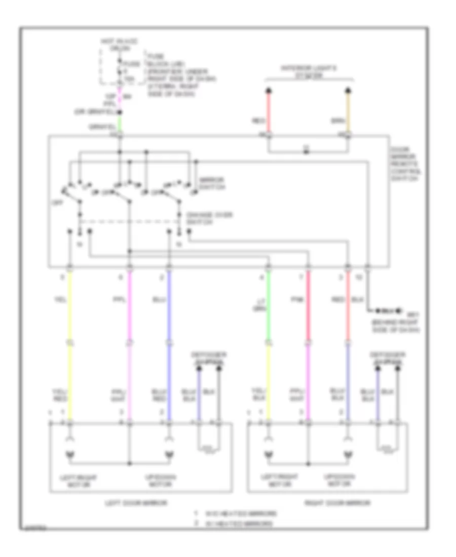
POWER MIRRORS
Power Mirror Wiring Diagram for Nissan Xterra Off Road 2005
List of elements for Power Mirror Wiring Diagram for Nissan Xterra Off Road 2005:
- 12p m4
- Change over switch
- Defogger system
- Door mirror remote control switch
- Fuse 10a
- Fuse block (j/b) (frontier: under right side of dash) (xterra: right side of dash)
- Hot in acc or on
- Interior lights system
- Left door mirror
- Left/right motor
- M61 (behind right side of dash)
- Mirror switch
- Off
- Pnk
- Red
- Right door mirror
- Up/down motor
- W/ heated mirrors
- W/o heated mirrors
POWER WINDOWS
Power Windows Wiring Diagram for Nissan Xterra Off Road 2005
List of elements for Power Windows Wiring Diagram for Nissan Xterra Off Road 2005:
- Acc sw
- B117 (under front passenger's seat)
- B7 (under driver's seat)
- Bat (f/l)
- Body control module (bcm) (under left side of dash)
- Can-h
- Can-l
- Closed
- Computer data lines system
- Cpu
- Door sw (as)
- Door sw (dr)
- Down
- Down relay
- Express down
- Fuse & fusible link box (right rear of engine compt)
- Fuse 10a
- Fuse block (j/b) (behind right end of dash)
- Fusible link g 50a
- Gnd
- Gnd (power)
- Hot at all times
- Hot in acc or on
- Hot in on or start
- Ign sw
- Illum
- Left front door switch (at base of left "b" pillar)
- Left front power window motor
- Left rear power window motor
- Left rear power window switch
- Lock
- M18
- M19
- M20
- M4 15p
- M57 (left "a" pillar)
- M79 (behind right side of dash)
- Main power window & door lock/ unlock switch
- Open
- Pnk
- Pwr win pwr supp (rap)
- Rap
- Red
- Right front door switch (at base of right "b" pillar)
- Right front power window motor
- Right power window & door lock/ unlock switch
- Right rear power window motor
- Right rear power window switch
- Unlck
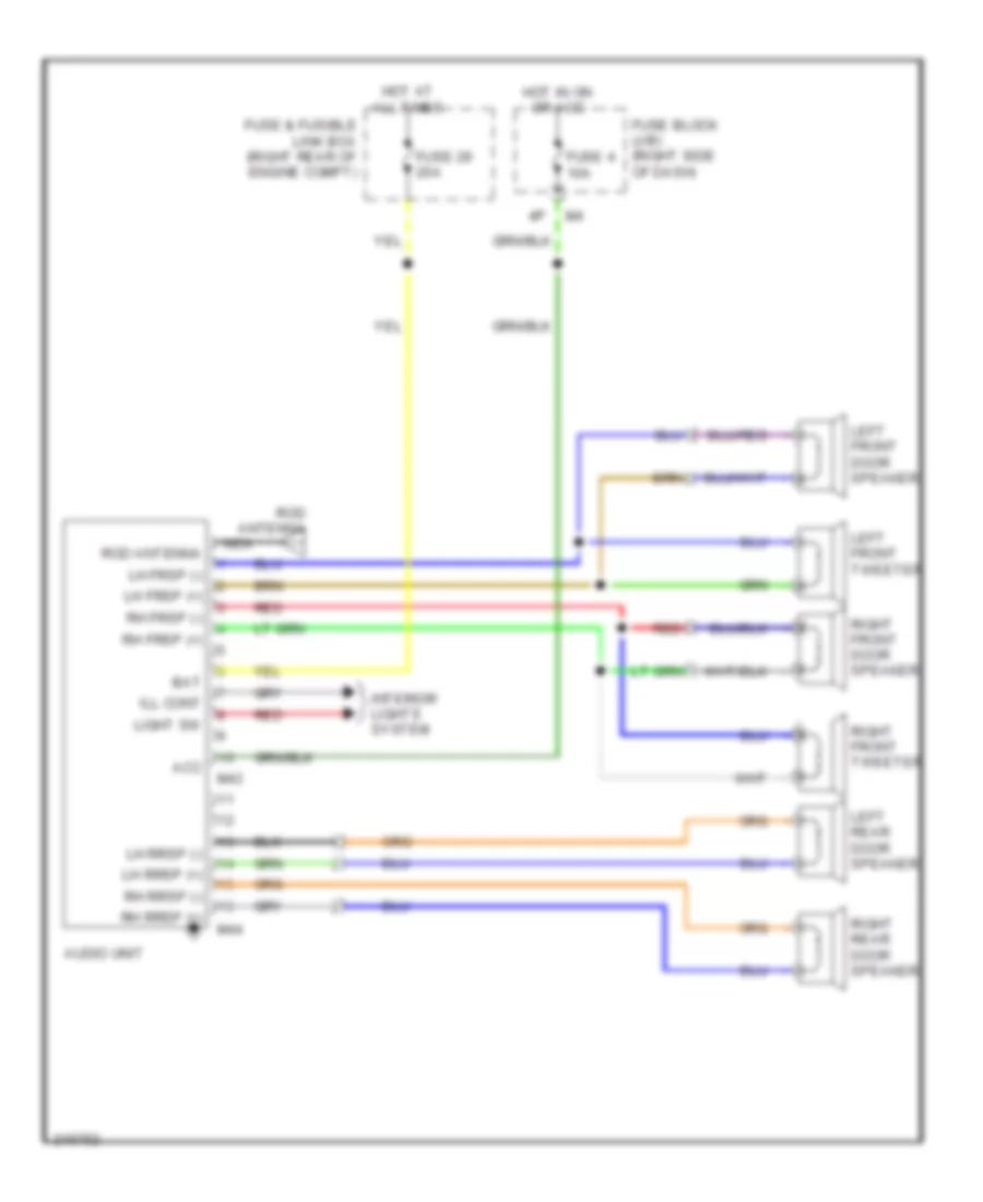
RADIO
Base Radio Wiring Diagram for Nissan Xterra Off Road 2005
List of elements for Base Radio Wiring Diagram for Nissan Xterra Off Road 2005:
- Acc
- Audio unit
- Bat
- Fuse & fusible link box (right rear of engine compt)
- Fuse 29 20a
- Fuse 4 10a
- Fuse block (j/b) (right side of dash)
- Hot at all times
- Hot in on or acc
- Ill cont
- Interior lights system
- Left front door speaker
- Left front tweeter
- Left rear door speaker
- Lh frsp (+)
- Lh frsp (-)
- Lh rrsp (+)
- Lh rrsp (-)
- Light sw
- M43
- M44
- Nca
- Red
- Rh frsp (+)
- Rh frsp (-)
- Rh rrsp (+)
- Rh rrsp (-)
- Right front door speaker
- Right front tweeter
- Right rear door speaker
- Rod antenna
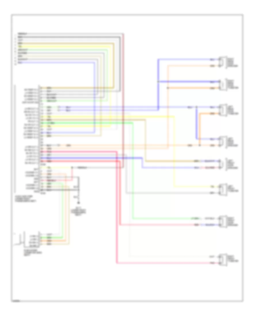
Premium Sound Radio Wiring Diagram (1 of 2) for Nissan Xterra Off Road 2005
List of elements for Premium Sound Radio Wiring Diagram (1 of 2) for Nissan Xterra Off Road 2005:
- 16p
- Acc
- Amp on/off sig
- Audio unit
- Backup
- Bat
- Combination meter
- Combination switch (spiral cable)
- Data
- Data earth
- Earth (sig)
- Fuse & fusible link box (right rear of engine compt)
- Fuse 10a
- Fuse 15a
- Fuse 29 20a
- Fuse block (j/b) (right side of dash)
- Gnd
- Hot at all times
- Hot in acc or on
- Ill cont
- Interior lights system
- L (+)
- L (-)
- Lh frsp (+)
- Lh frsp (-)
- Lh rrsp (+)
- Lh rrsp (-)
- Light sw
- M42
- M43
- M44
- M45
- Mode switch
- Nca
- Pnk
- Power switch
- R (+)
- R (-)
- Red
- Req
- Req1
- Rh frsp (+)
- Rh frsp (-)
- Rh rrsp (+)
- Rh rrsp (-)
- Rod antenna
- Rxd
- Sat lch (+)
- Sat lch (-)
- Sat rch (+)
- Sat rch (-)
- Satellite radio tuner (pre-wiring) (behind left side of dash)
- Seek switch
- Spped out
- Steering wheel audio control switches
- Strg sw a (up)
- Strg sw b (dn)
- Strg sw c (gnd)
- Txd
- Volume switch
Premium Sound Radio Wiring Diagram (2 of 2) for Nissan Xterra Off Road 2005
List of elements for Premium Sound Radio Wiring Diagram (2 of 2) for Nissan Xterra Off Road 2005:
- Amp on/off sig
- Audio amplifier (under front passenger's seat)
- B117 (under front passenger's seat)
- B158
- B159
- Bat
- Fr out (+)
- Gnd
- Left front door speaker
- Left front tweeter
- Left rear door speaker
- Left rear door tweeter
- Lf rr (+)
- Lh fr out (-)
- Lh fr tw (+)
- Lh fr tw (-)
- Lh frsp in (+)
- Lh frsp in (-)
- Lh rr (-)
- Lh rr out (+)
- Lh rr out (-)
- Lh rrsp in (+)
- Lh rrsp in (-)
- Pnk
- Red
- Rh fr out (+)
- Rh fr out (-)
- Rh fr tw (+)
- Rh fr tw (-)
- Rh frsp in (+)
- Rh frsp in (-)
- Rh rr (+)
- Rh rr (-)
- Rh rr out (-)
- Rh rrsp in (+)
- Rh rrsp in (-)
- Right front door speaker
- Right front tweeter
- Right rear door speaker
- Right rear door tweeter
- Rr rh out (+)
- Subwoofer (under driver's seat)
- Woofer (+)1
- Woofer (+)2
- Woofer (-)1
- Woofer (-)2
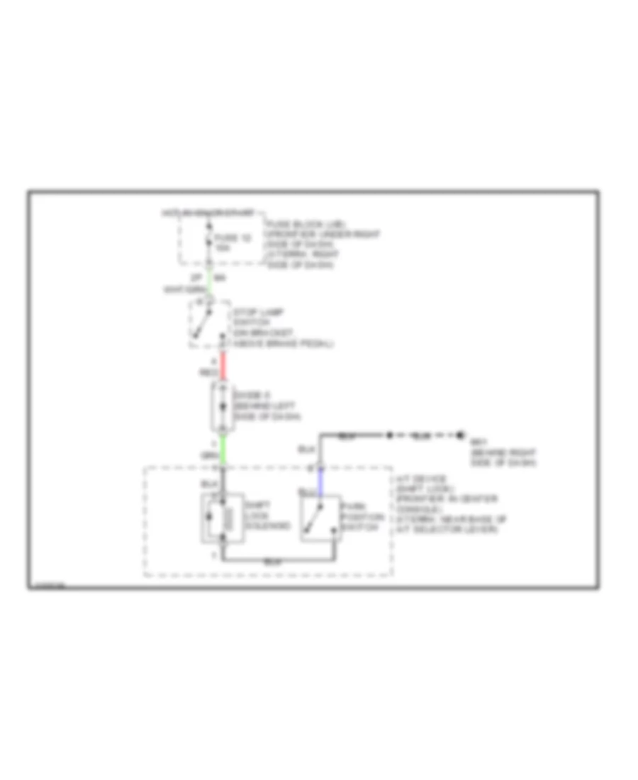
SHIFT INTERLOCK
Shift Interlock Wiring Diagram for Nissan Xterra Off Road 2005
List of elements for Shift Interlock Wiring Diagram for Nissan Xterra Off Road 2005:
- A/t device (shift lock) (frontier: in center console) (xterra: near base of a/t selector lever)
- Diode-5 (behind left side of dash)
- Fuse 12 10a
- Fuse block (j/b) (frontier: under right side of dash) (xterra: right side of dash)
- Hot in on or start
- M61 (behind right side of dash)
- Park position switch
- Red
- Shift lock solenoid
- Stop lamp switch (on bracket, above brake pedal)
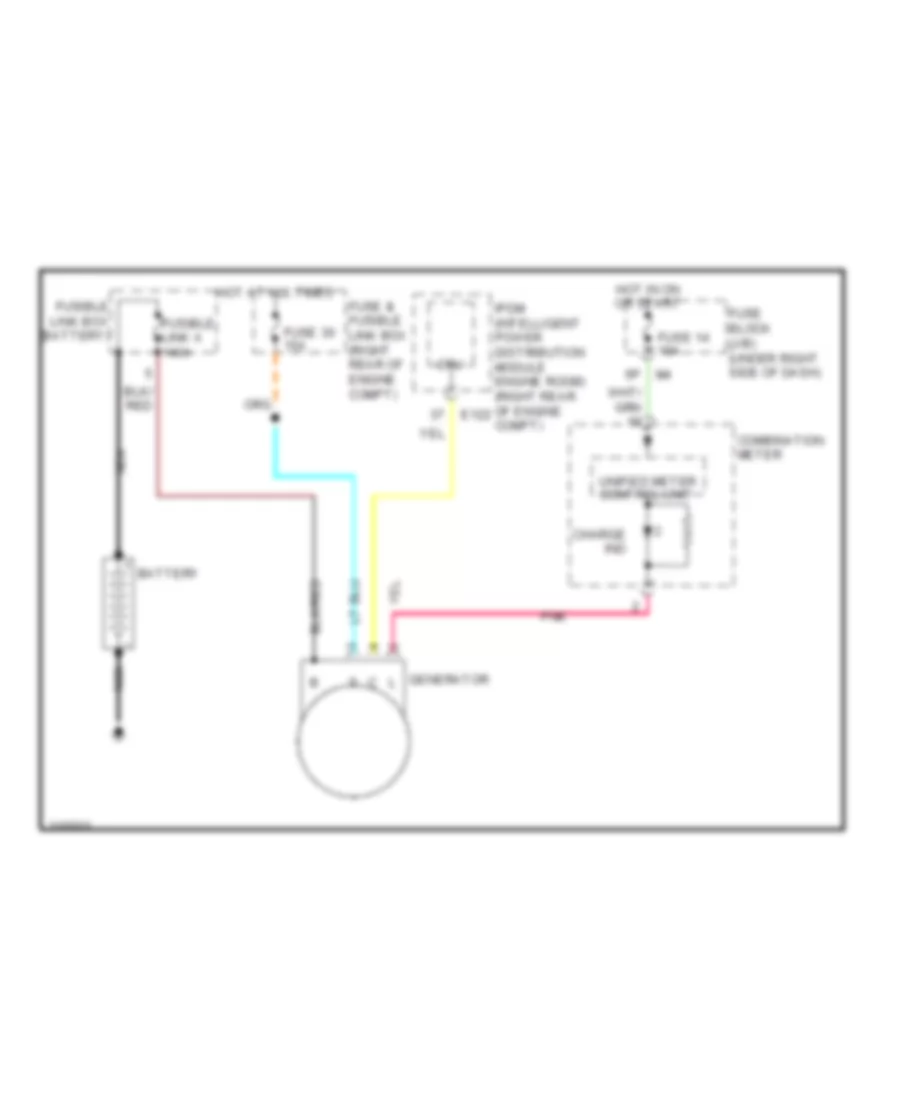
STARTING/CHARGING
Charging Wiring Diagram for Nissan Xterra Off Road 2005
List of elements for Charging Wiring Diagram for Nissan Xterra Off Road 2005:
- Battery
- Charge ind
- Combination meter
- Cpu
- Fuse & fusible link box (right rear of engine compt)
- Fuse 14 10a
- Fuse 30 15a
- Fuse block (j/b) (under right side of dash)
- Fusible link a 140a
- Fusible link box (battery)
- Generator
- Hot at all times
- Hot in on or start
- Ipdm (intelligent power distribution module engine room) (right rear of engine e122 compt)
- Nca
- Pnk
- Unified meter control unit
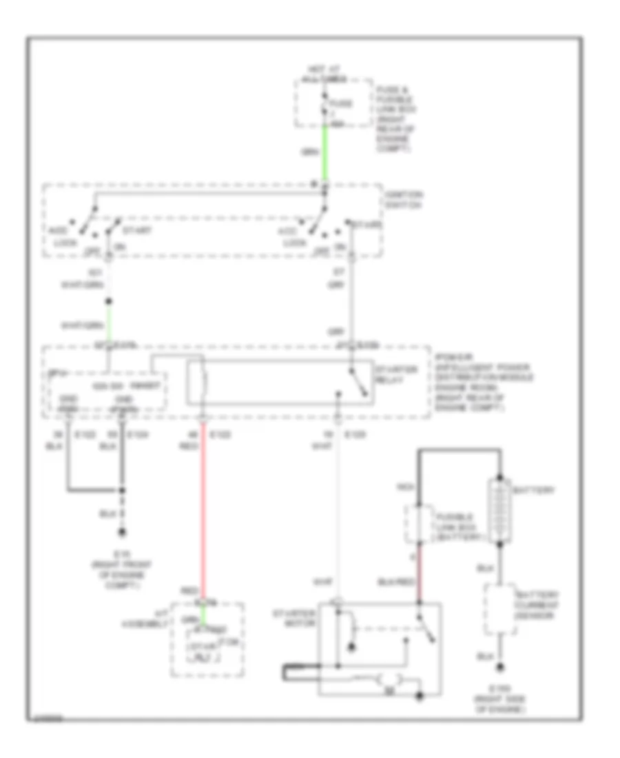
Starting Wiring Diagram, A/T for Nissan Xterra Off Road 2005
List of elements for Starting Wiring Diagram, A/T for Nissan Xterra Off Road 2005:
- A/t assembly
- Acc
- Acc acc
- Battery
- Battery current sensor
- Cpu
- E119
- E120
- E122
- E124
- E15 (right front of engine compt)
- E150 (right side of engine)
- Fuse & fusible link box (right rear of engine compt)
- Fuse j 40a
- Fusible link box (battery)
- Gnd (pwr)
- Gnd (sig)
- Hot at all times
- Ig1
- Ign sw
- Ignition switch
- Inhibit
- Ipdm e/r (intelligent power distribution module engine room) (right rear of engine compt)
- Lock
- Nca
- Off
- Red
- Star rly
- Start
- Starter motor
- Starter relay
- Tcm
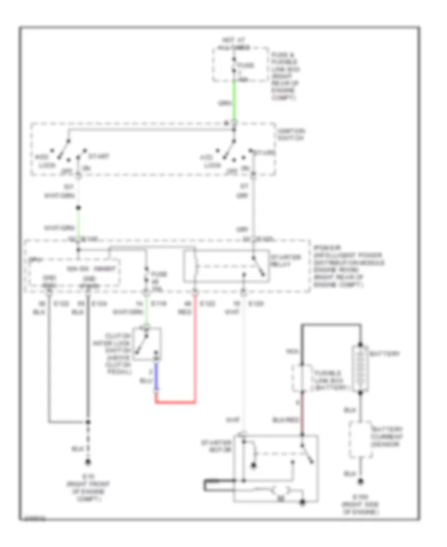
Starting Wiring Diagram, M/T with Clutch Interlock for Nissan Xterra Off Road 2005
List of elements for Starting Wiring Diagram, M/T with Clutch Interlock for Nissan Xterra Off Road 2005:
- (right front of engine compt)
- (right front of engine compt) e15
- Acc
- Acc acc
- Battery
- Battery current
- Cancel
- Clutch interlock cancel relay 1 (right rear of engine compt)
- Clutch interlock cancel relay 2 (right rear of engine compt)
- Clutch interlock cancel switch (on bracket, above clutch pedal)
- Clutch interlock switch (above clutch pedal)
- Cpu
- Diode 3 (right side of engine compt)
- E119
- E120
- E122
- E124
- E15
- E15 (right front of engine compt)
- E150 (right side of engine)
- Fuse & fusible link box (right rear of engine compt)
- Fuse 10a
- Fuse j 40a
- Fusible link box (battery)
- Gnd (pwr)
- Gnd (sig)
- Hot at all times
- Ig1
- Ign sw
- Ignition switch
- Illumination
- Inhibit
- Interior lights system
- Ipdm e/r (intelligent power distribution module engine room) (right rear of engine compt)
- Lock
- M61 (behind right side of dash)
- Motor
- Nca
- Off
- Red
- Sensor
- Start
- Starter
- Starter relay
Starting Wiring Diagram, M/T without Clutch Interlock for Nissan Xterra Off Road 2005
List of elements for Starting Wiring Diagram, M/T without Clutch Interlock for Nissan Xterra Off Road 2005:
- Acc
- Acc acc
- Battery
- Battery current sensor
- Clutch inter lock switch (above clutch pedal)
- Cpu
- E119
- E120
- E122
- E124
- E15 (right front of engine compt)
- E150 (right side of engine)
- Fuse & fusible link box (right rear of engine compt)
- Fuse 10a
- Fuse j 40a
- Fusible link box (battery)
- Gnd (pwr)
- Gnd (sig)
- Hot at all times
- Ig1
- Ign sw
- Ignition switch
- Inhibit
- Ipdm e/r (intelligent power distribution module engine room) (right rear of engine compt)
- Lock
- Nca
- Off
- Red
- Start
- Starter motor
- Starter relay
SUPPLEMENTAL RESTRAINTS
Supplemental Restraints Wiring Diagram (1 of 2) for Nissan Xterra Off Road 2005
List of elements for Supplemental Restraints Wiring Diagram (1 of 2) for Nissan Xterra Off Road 2005:
- (behind center of dash) m61
- (lower left side of dash)
- (on right front side of engine compartment) e14
- Air bag
- Air bag diagnosis sensor unit (under rear of center console)
- As1 +
- As1 -
- As2 +
- As2 -
- B113
- B117 (under right front seat)
- B7 (under left front seat)
- Buckle sw lh
- Buckle sw rh
- Clh +
- Clh -
- Combination meter
- Combination switch (spiral cable)
- Crash zone sensor (at front center of vehicle, behind front grille)
- Crh +
- Crh -
- Czs-shld
- Data link connector (partial)
- Dr1 (-) dr2 (-)
- Dr1 +
- Dr2 +
- Driver air bag module
- Driver side seat belt buckle switch (in driver's seat belt buckle)
- Eczs +
- Eczs -
- Fastened
- Fuse 10a
- Fuse block (j/b) (behind left kick panel)
- Gnd
- Hot in on or start
- Ignition
- K-line
- Left ext lock -
- Left front seat belt pre-tensioner
- Left front side air bag module
- Left sat +
- Left sat -
- M101
- M103
- M24
- M35
- M57 (behind left side of dash)
- Nca
- Ods-led
- Passenger side seat belt buckle switch (in passenger's seat belt buckle)
- Plh +
- Plh -
- Prh +
- Prh -
- Red
- Right front seat belt pre-tensioner
- Right front side air bag module
- Right sat +
- Right sat -
- Slh1 +
- Slh1 -
- Srh +
- Srh -
- Un- fastened
- Unified meter control unit
- Warn-lp
Supplemental Restraints Wiring Diagram (2 of 2) for Nissan Xterra Off Road 2005
List of elements for Supplemental Restraints Wiring Diagram (2 of 2) for Nissan Xterra Off Road 2005:
- (on left "b" pillar) b5
- (on right "b" pillar) b112
- Belt tension sensor (at lower right"b: pillar)
- Front passenger air bag module
- Front passenger airbag off indicator
- Left side air bag (satellite sensor) (at base of left "b" pillar)
- Left side curtain air bag module
- M117
- M61 (behind center off dash)
- Nca
- Occupant classification system control (under front passenger's seat)
- Red
- Right side air bag (satellite sensor) (at base of right "b" pillar)
- Right side curtain air bag module
- Seat pressure sensor (under right front seat)
- Under right front seat)
TRANSMISSION
4WD Wiring Diagram, A/T (1 of 2) for Nissan Xterra Off Road 2005
List of elements for 4WD Wiring Diagram, A/T (1 of 2) for Nissan Xterra Off Road 2005:
- 2wd ind
- 2wd sw
- 4 lo switch (on transfer case)
- 4h sw
- 4hi ind
- 4lo ind
- 4lpos sw
- 4wd fail
- 4wd ind
- 4wdposw
- Acc
- Actr sw1
- Actr sw2
- Actr sw3
- Actr sw4
- Atp ind
- Atp sw
- Atp switch (on transfer case)
- Can-h
- Can-l
- Combination meter
- Computer data lines system
- Data link connector (under left side of dash)
- E152
- E153
- E24
- Fuse 10a
- Fuse block (j/b) (right side of dash)
- Gnd
- Hot at all times
- Hot in on or start
- Ign sw
- Ignition switch
- Kline
- Lock
- Lock ind
- M61 (behind right side of dash)
- Mem b/u
- Mtr +
- Mtr -
- Mtrmon1
- Mtrmon2
- Mtrrly1
- Mtrrly2
- Pnk
- Red
- Run
- Ssof
- Start
- Transfer control unit (behind left side of dash)
- Unified meter control unit
- Vign
- Wait detection switch (on transfer case)
4WD Wiring Diagram, A/T (2 of 2) for Nissan Xterra Off Road 2005
List of elements for 4WD Wiring Diagram, A/T (2 of 2) for Nissan Xterra Off Road 2005:
- (right rear of engine compt) transfer relay 1
- 2wd
- 4lo
- 4wd shift switch
- Actr sw 1
- Actr sw 2
- Actr sw 3
- Actr sw 4
- E24
- Fuse & fusible link box (right rear of engine compt)
- Fuse & relay box (right side of engine compt)
- Fuse 10a
- Fuse j 40a
- Hot at all times
- Interior lights system
- Red
- Transfer control device (actuator position switch)
- Transfer relay 2 (right rear of engine compt)
- Transfer shut off relay 1 (right rear of engine compt)
- Transfer shut off relay 2 (right rear of engine compt)
4WD Wiring Diagram, M/T (1 of 2) for Nissan Xterra Off Road 2005
List of elements for 4WD Wiring Diagram, M/T (1 of 2) for Nissan Xterra Off Road 2005:
- 2wd ind
- 2wd sw
- 4 lo switch (on transfer case)
- 4h sw
- 4hi ind
- 4lo ind
- 4lpos sw
- 4wd fail
- 4wd ind
- 4wdposw
- Acc
- Actr sw1
- Actr sw2
- Actr sw3
- Actr sw4
- Can-h
- Can-l
- Combination meter
- Computer data lines system
- Data link connector (under left side of dash)
- E15 (right front of engine compt)
- E152
- E153
- E24
- Fuse 10a
- Fuse block (j/b) (right side of dash)
- Gnd
- Hot at all times
- Hot in on or start
- Ign sw
- Ignition switch
- Kline
- Lock
- Lock ind
- M61 (behind right side of dash)
- Mem b/u
- Mtr +
- Mtr -
- Mtrmon1
- Mtrmon2
- Mtrrly1
- Mtrrly2
- Neut sw
- Park/ neutral position switch (on top of transmission)
- Pnk
- Red
- Run
- Ssof
- Start
- Transfer control unit (behind left side of dash)
- Unified meter control unit
- Vign
- Wait detection switch (on transfer case)
4WD Wiring Diagram, M/T (2 of 2) for Nissan Xterra Off Road 2005
List of elements for 4WD Wiring Diagram, M/T (2 of 2) for Nissan Xterra Off Road 2005:
- (right rear of engine compt) transfer relay 1
- 2wd
- 4lo
- 4wd shift switch
- Actr sw 1
- Actr sw 2
- Actr sw 3
- Actr sw 4
- E24
- Fuse & fusible link box (right rear of engine compt)
- Fuse & relay box (right side of engine compt)
- Fuse 10a
- Fuse j 40a
- Hot at all times
- Interior lights system
- Red
- Transfer control device (actuator position switch)
- Transfer relay 2 (right rear of engine compt)
- Transfer shut off relay 1 (right rear of engine compt)
- Transfer shut off relay 2 (right rear of engine compt)
A/T Wiring Diagram (1 of 2) for Nissan Xterra Off Road 2005
List of elements for A/T Wiring Diagram (1 of 2) for Nissan Xterra Off Road 2005:
- A/t assembly
- A/t fluid temperature sensor 1
- A/t fluid temperature sensor 2
- Atf sens 2+
- Atf sens 2-
- Atf sens1+
- Atf sens1-
- Batt-1
- Batt-2
- C1 (vin)
- C2 (vout)
- C3 (gnd)
- Can-h
- Can-l
- Common
- Control module (tcm)
- Data link connector (under left side of dash)
- Direct clutch solenoid
- Exterior lights system
- F10 (top left side of engine)
- F502
- F503
- F504
- F505
- F506
- Front brake solenoid
- Gnd
- Gnd-1
- Gnd-2
- High & low reverse clutch solenoid
- Inh-sw1
- Inh-sw2
- Inh-sw3
- Inh-sw4
- Input clutch solenoid
- K-line
- Line pressure solenoid
- Linear sol
- Low coast brake solenoid
- Oil press switch 1
- Oil press switch 2
- Oil press switch 3
- Oil press switch 5
- Oil press switch 6
- Park/neutral position switch
- Pnk
- Pressure switch 1 (fr/b)
- Pressure switch 2 (lc/b)
- Pressure switch 3 (i/c)
- Pressure switch 5 (d/c)
- Pressure switch 6 (hlr/c)
- Red
- Rev rly
- Rev sen gnd
- Rev sen vin
- Rev sen vout
- Revolution sensor
- Start rly
- Starting/ charging system
- Torque converter clutch solenoid
- Transmission
- Turbine revolution sensor 1
- Turbine revolution sensor 2
- Turbine sens 2
- V out
- Vcc
- Vign
A/T Wiring Diagram (2 of 2) for Nissan Xterra Off Road 2005
List of elements for A/T Wiring Diagram (2 of 2) for Nissan Xterra Off Road 2005:
- 1st pos switch
- A/t device
- Can-h
- Can-l
- Combination meter
- Computer data lines system
- Ecm (right rear of engine compt)
- Fuse 10a
- Fuse block (j/b) (right side of dash)
- Hot at all times
- Hot in on or start
- Ipdm e/r (at right rear of engine compt)
- M57 (left "a" pillar)
- M61 (behind
- M61 (behind right side of dash)
- O/d off indicator
- Od control switch
- Pnk
- Right side of dash)
- Unified meter control unit
WARNING SYSTEMS
Warning Systems Wiring Diagram for Nissan Xterra Off Road 2005
List of elements for Warning Systems Wiring Diagram for Nissan Xterra Off Road 2005:
- 15p
- Air bag diagnosis sensor unit (under console box)
- B7 (under driver's seat)
- Bat
- Body control module (bcm) (under left side of dash)
- Buzzer
- Can-h
- Can-l
- Combi sw input 1
- Combi sw input 2
- Combi sw input 3
- Combi sw input 4
- Combi sw input 5
- Combi sw output 1
- Combi sw output 2
- Combi sw output 3
- Combi sw output 4
- Combi sw output 5
- Combination
- Combination meter
- Computer data lines system
- Door ind
- Door sw (dr)
- Fuse & fusible link box (right rear of engine compt)
- Fuse 10a
- Fuse block (j/b) (right side of dash)
- Fusible link g 50a
- Gnd
- Hot at all times
- Hot in on or start
- Ign sw
- Input 1
- Input 2
- Input 3
- Input 4
- Input 5
- Key sw
- Key switch
- Left front door switch (at base of left "b" pillar)
- Left seat belt buckle switch (in driver's seat belt buckle assembly)
- M18
- M19
- M20
- M61 (behind right side of dash)
- Output 1
- Output 2
- Output 3
- Output 4
- Output 5
- P/ warn check
- Pnk
- Pwr
- Red
- Remote keyless entry receiver
- Seat belt ind
- Signal
- Switch
- Tire pressure ind
- Tire pressure warning check connector
- Tuner sens gnd
- Unified meter control unit
WIPER/WASHER
Front Wiper/Washer Wiring Diagram for Nissan Xterra Off Road 2005
List of elements for Front Wiper/Washer Wiring Diagram for Nissan Xterra Off Road 2005:
- Combination meter
- Combination switch
- Cpu
- E121
- E122
- E9 (left side of engine compt)
- Front washer motor (xterra: right rear of engine compt) (frontier: right side of engine compt)
- Front wiper high relay
- Front wiper motor (xterra: on left side of firewall) (frontier: rear of engine compt)
- Front wiper relay
- Fuse 10a
- Fuse 39 30a
- Fuse block (j/b) (xterra: right side of dash) (frontier: under right side of dash)
- Gnd
- High
- Hot at all times
- Hot in on or start
- Ign
- Ignition relay
- Ind washer
- Ipdm e/r (right rear of engine compt)
- Low
- M57 (xterra: left "a" pillar) (frontier: behind left side of dash)
- Unified meter control unit
- Washer fluid level switch (right side of engine compt)
- Washer motor (fr+)
- Washer motor (fr-)
Rear Wiper/Washer Wiring Diagram for Nissan Xterra Off Road 2005
List of elements for Rear Wiper/Washer Wiring Diagram for Nissan Xterra Off Road 2005:
- 15p
- Auto-stop
- Body control module (bcm) (at center of backdoor)
- Combination switch
- D406 (left side of tailgate)
- Fuse 1 10a
- Fuse 15 10a
- Fuse block (j/b) (right side of dash)
- Gnd
- Gnd (power)
- Hot in on or start
- Ign
- Ign sw
- M57 (left "a" pillar)
- Rear washer motor (right rear of engine compt)
- Rear wiper motor (at center of tailgate)
- Rr wiper o/p (mtr)
- Washer motor (fr+)
- Washer motor (fr-)