Diagram sections — 29 (37 total)
AIR CONDITIONING ANTI-LOCK BRAKES ANTI-THEFT BODY COMPUTER COMPUTER DATA LINES COOLING FAN CRUISE CONTROL DEFOGGERS ENGINE PERFORMANCE EXTERIOR LIGHTS GROUND DISTRIBUTION HEADLIGHTS HORN INSTRUMENT CLUSTER INTERIOR LIGHTS POWER DISTRIBUTION POWER DOOR LOCKS POWER MIRRORS POWER SEATS POWER TOP/SUNROOF POWER WINDOWS RADIO SHIFT INTERLOCKS STARTING/CHARGING SUPPLEMENTAL RESTRAINTS TRANSMISSION TRUNK, TAILGATE, FUEL DOOR WARNING SYSTEMS WIPER/WASHER
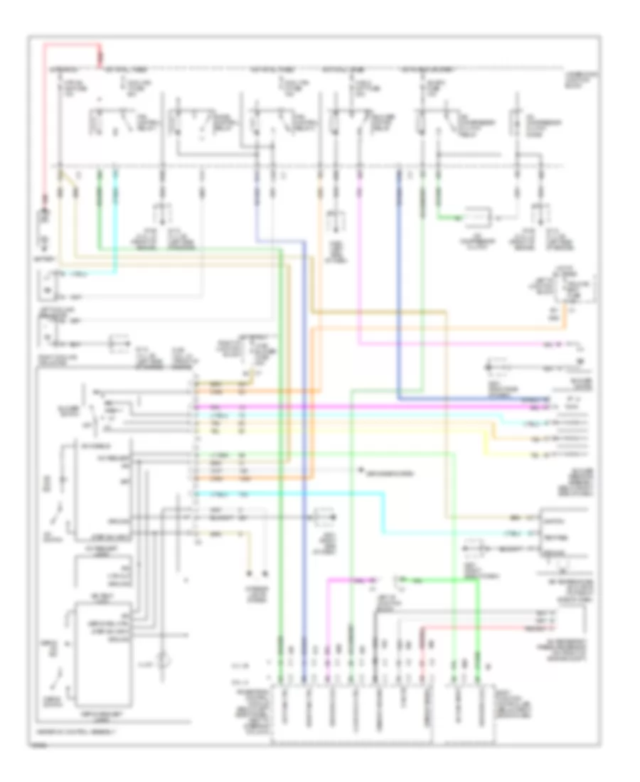
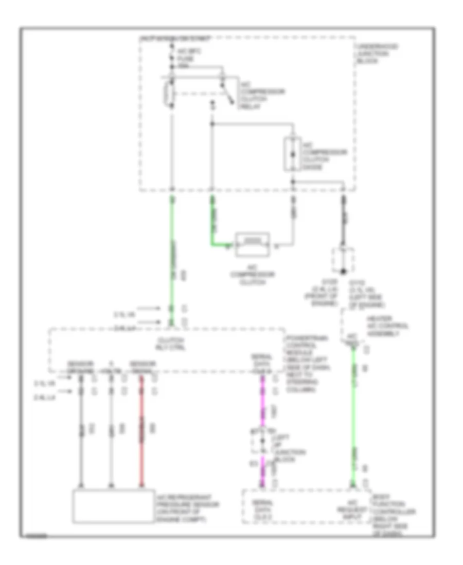
AIR CONDITIONING A/C Wiring Diagram for Oldsmobile Cutlass GL 1998 List of elements for A/C Wiring Diagram for Oldsmobile Cutlass GL 1998: 75 2.4l l4 3.1l v6 5 volts A/c bfc fuse 10a A/c compressor clutch A/c compressor clutch diode A/c compressor clutch relay A/c disable A/c on ind A/c refigerant pressure sensor (on front of engine compt) A/c req input A/c request A/c request logic A/c switch A10 A11 Air temp logic Air temperature actuator (top right side of dash) B11 Bat Battery Blower motor Blower motor relay Blower resistor assembly (below right side of dash) Blower switch Body function controller (below right side of dash) C10 Clutch rly ctrl Cool fan 1 fuse 30a Cool fan 2 fuse 15a D10 D11 Defog on ind Defog rel ctrl Defog request logic Defog switch Defogger system F11 Fan control relay 1 Fan control relay 2 G112 (3.1l v6) (left side of engine) G125 (2.4l l4) (front of engine) G201 (right side of dash) G202 (left side of dash) Ground Heater a/c control assembly Hi blo mot fuse 30a Hot at all times Hot in run Hot in run or start Htr a/c ign fuse 10a Htr out Hvac blower fuse 20a Ign Ignition Illum Interior lights system Ipc/hvac batt fuse 10a Left cooling fan motor Left fan ctrl Left i/p junction block Mode control relay Off Powertrain control module (below left side ofdash, next to steering column) Red Right cooling fan motor Right fan ctrl Right i/p junction block Sensor ground Sensor signal Ser data cls 2 Step dim input Tan Temp req Underhood junction block Compressor Wiring Diagram for Oldsmobile Cutlass GL 1998 List of elements for Compressor Wiring Diagram for Oldsmobile Cutlass GL 1998: 22 2.4l l4 3.1l v6 A/c bfc fuse 10a A/c compressor clutch A/c compressor clutch diode A/c compressor clutch relay A/c refrigerant pressure sensor (on front of engine compt) A/c req A/c request input Body function controller (below right side of dash) Clutch rly ctrl G112 (3.1l v6) (left side of engine) G125 (2.4l l4) (front of engine) Heater a/c control assembly Hot in run or start Left i/p junction block Powertrain control module (below left side of dash, next to steering column) Sensor ground Sensor signal Serial data cls 2 Underhood junction block Volts
ANTI-LOCK BRAKES Anti-lock Brake Wiring Diagrams for Oldsmobile Cutlass GL 1998 List of elements for Anti-lock Brake Wiring Diagrams for Oldsmobile Cutlass GL 1998: 67 A10 A12 Abs actuator motor assembly (left front of engine compt) Abs ind. Abs rly ctrl Battery Body function controller (below right side of dash) Brake Brake fluid level Brake fluid level switch (rear of engine compt) Brake switch (brake pedal support) Data line Electronic brake control module (ebcm) (inside left front fender) Electronic brake control relay Enable rly output Evo/ abs sol fuse 15a F12 Fuse block G125 (vin t) g112 (vin m) (lower front of engine) (vin t) (left side of engine) (vin m) Ground Hot at all times Hot in run or start Icc bat fuse 10a Icc fuse 40a Icc ign fuse 10a Ign Ignition Ind. Ind. ctrl Instrument cluster L fnt mtr-hi L fnt mtr-lo Left front abs solenoid (left front corner of engine compt) Left front motor Left front wheel speed sensor Left i/p wiring harness junction block Left rear wheel speed sensor Lf abs sol ctrl Lf spd sens rtn Lf spd sensor Lr spd sens rtn Lr spd sensor Microprocessor Nca Pnk Powertrain control module (left side of dash) Rear motor Rear mtr-hi Rear mtr-lo Red Rf sol ctrl Rf spd sens rtn Rf spd sensor Right front abs solenoid (right front corner of engine compt) Right front motor Right front wheel speed sensor Right rear wheel speed sensor Rr spd dens rtn Rr spd sensor Rt fnt mtr-hi Rt fnt mtr-lo Serial data Stop lamp feed Stop lps fuse 15a Tan Underhood bussed electrical center Underhood wiring harness junction block
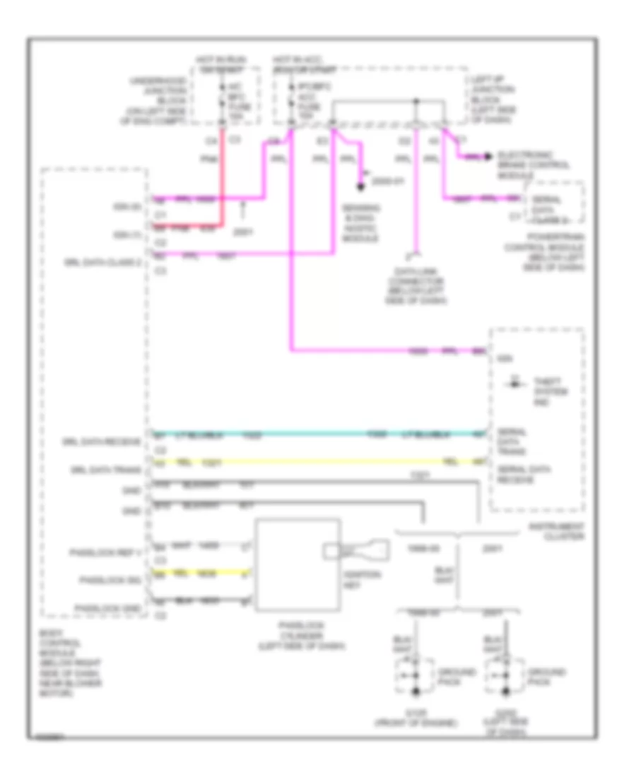
ANTI-THEFT Anti-theft Wiring Diagram for Oldsmobile Cutlass GL 1998 List of elements for Anti-theft Wiring Diagram for Oldsmobile Cutlass GL 1998: 36 1998-00 2000-01 A/c bfc fuse 10a A10 B10 Body control module (below right side of dash, near blower motor) Data link connector (below left side of dash) Electronic brake control module G125 (front of engine) G202 (left side of dash) Gnd Ground pack Hot in acc, run or start Hot in run or start Ign Ign (0) Ign (1) Ignition key Instrument cluster Ipc/bfc acc fuse 10a Left i/p junction block (left side of dash) Passlock cylinder (left side of dash) Passlock gnd Passlock ref v Passlock sig Pnk Powertrain control module (below left side of dash) Sensing & diag- nostic module Serial data class 2 Serial data receive Serial data trans Srl data class 2 Srl data receive Srl data trans Theft system ind Underhood junction block (on left side of eng compt)
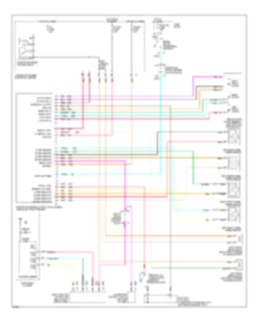
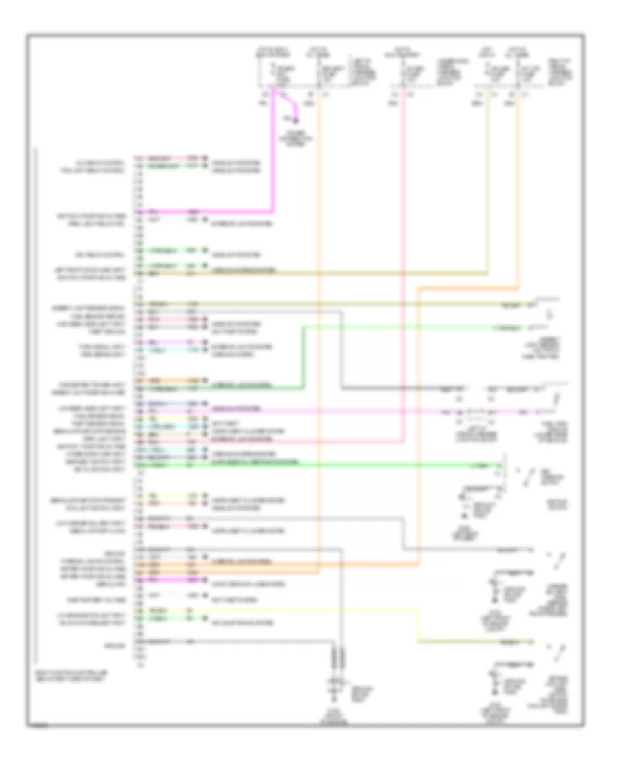
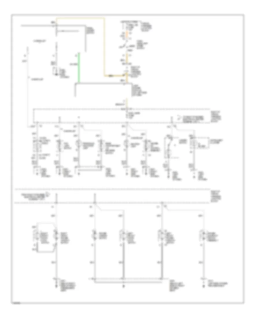
BODY COMPUTER Body Computer Wiring Diagrams for Oldsmobile Cutlass GL 1998 List of elements for Body Computer Wiring Diagrams for Oldsmobile Cutlass GL 1998: 76 A/c bfc fuse 10a A/c switch request input A10 A11 A12 Air conditioning system Alc relay control Ambient lght snsr sig 5v ref Ambient light sensor (on top of dash trim pad) Ambient light sensor signal Anti-theft Anti-theft system B10 B11 B12 Battery positive voltage Bfc batt fuse 10a Body function controller (below right side of dash) Computer data lines system Cruise fuse 10a Drl relay control Engine coolant level switch (on engine coolant surge tank) Exterior lights system Fog light relay control Fog light switch input Fuel sensor return Fuel sensor signal Fuel tank module (under rear of vehicle) G100 (left front of engine compt) G125 (front of engine) G202 (left side of dash) Ground Ground splice pack Headlights system High beam headlight input Hot at all times Hot in accy, run or start Hot in run Hot in run or start Ignition 0 positive voltage Ignition 1 positive voltage Ignition 3 positive voltage Ignition switch Inadvertent power input Instrument cluster system Int lps fuse 10a Interior lights control Interior lights system Ipc/bfc acc fuse 10a Key in ignition input Key warning switch Left front door ajar input Left i/p wiring harness junction block Low beam headlight input Low engine coolant input Low washer solvent input Other door ajar input Park brake input Park light input Park light relay ctrl Pnk Power distribution system Right i/p wiring harness junction block Seat belt switch input Serial data Serial data spi clock Serial data spi data receive Serial data spi data transmit Theft battery voltage Theft ground Theft sensor signal Turn signal input Underhood wiring harness junction block Warning system Warning systems system Washer solvent level sensor (inside left front fender)
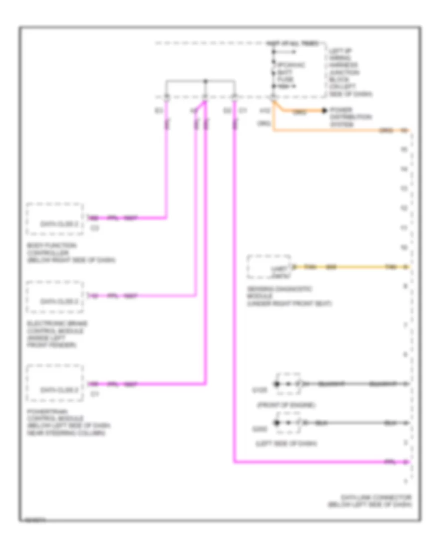
COMPUTER DATA LINES Computer Data Lines for Oldsmobile Cutlass GL 1998 List of elements for Computer Data Lines for Oldsmobile Cutlass GL 1998: 17 (front of engine) (left side of dash) A12 Body function controller (below right side of dash) Data clss 2 Data link connector (below left side of dash) Electronic brake control module (inside left front fender) G125 G202 Hot at all times Ipc/hvac batt fuse 10a Left i/p wiring harness junction block (on left side of dash) Power distribution system Powertrain control module (below left side of dash, near steering column) Sensing diagnostic module (under right front seat) Tan Uart data
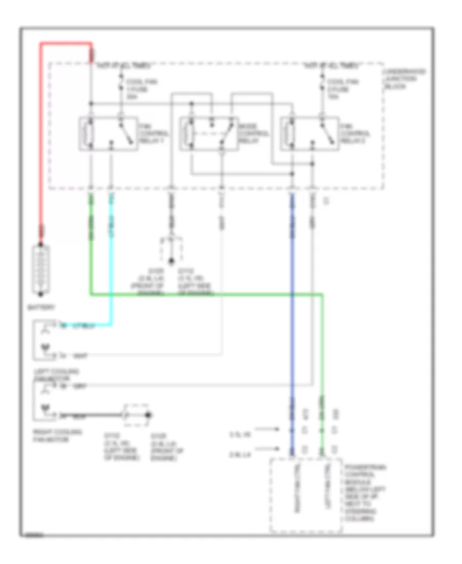
COOLING FAN Cooling Fan Wiring Diagram for Oldsmobile Cutlass GL 1998 List of elements for Cooling Fan Wiring Diagram for Oldsmobile Cutlass GL 1998: 22 2.4l l4 3.1l v6 Battery C10 Cool fan 1 fuse 30a Cool fan 2 fuse 15a D10 D11 F11 Fan control relay 1 Fan control relay 2 G112 (3.1l v6) (left side of engine) G125 (2.4l l4) (front of engine) Hot at all times Left cooling fan motor Left fan ctrl Mode control relay Powertrain control module (below left side of i/p, next to steering column) Red Right cooling fan motor Right fan ctrl Underhood junction block
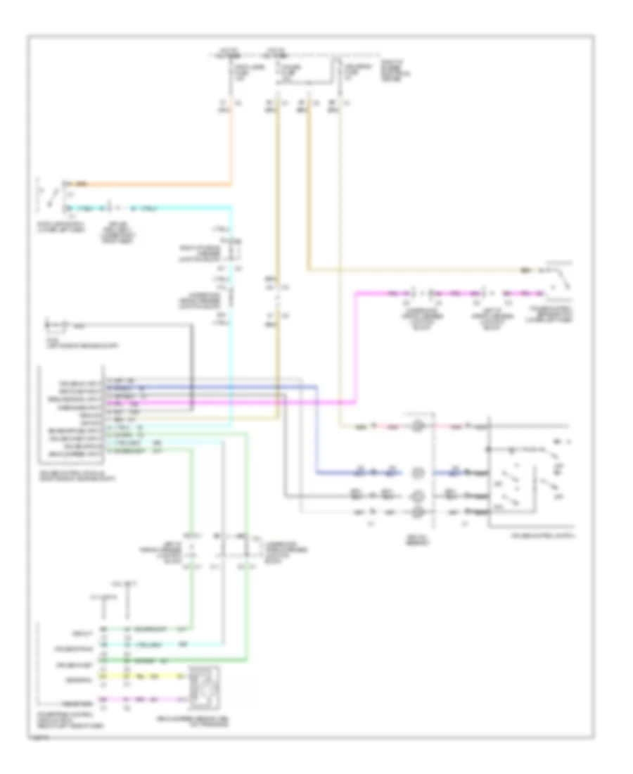
CRUISE CONTROL Cruise Control Wiring Diagram for Oldsmobile Cutlass GL 1998 List of elements for Cruise Control Wiring Diagram for Oldsmobile Cutlass GL 1998: 45 (2.4l vin t) (3.1l vin m) A11 All times B12 C1 c3 C11 C4 c1 Cruise control brake switch (lower left dash) Cruise control module (right side of engine compt) Cruise control switch Cruise fuse 10a Cruise inhibit Cruise inhibit input Cruise on input Cruise status Cruise sw fuse 2a Disengage input F12 F6 c1 G100 (left side of engine compt) Ground Hot at Ignition Left i/p wiring harness junction block Nca Off Pnk Powertrain control module (pcm) (below left side of dash) R/a Resume/accel input Right i/p bussed electrical center Right i/p wiring harness junction block S/c Set/coast input Sir coil assembly Splice pack (s301) (under right front seat) Stop lamp switch (lower left dash) Stop lamps fuse 15a Underhood wiring harness junction block Vehicle speed input Vehicle speed sensor (vss) (on transaxle) Vss out Vss return Vss signal
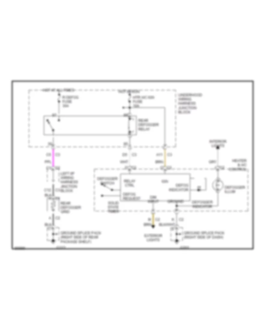
DEFOGGERS Defogger Wiring Diagram for Oldsmobile Cutlass GL 1998 List of elements for Defogger Wiring Diagram for Oldsmobile Cutlass GL 1998: 36 A c2 A11 c3 C c2 C1 c2 C2 d C2 j C3 c12 C3 c5 D5 c3 Defog indicator Defog request Defogger illum Defogger indicator Defogger switch Dim input Exterior lights G201 G313 Ground Ground splice pack (right side of dash) Ground splice pack (right side of rear package shelf) Heater & a/c control Hot at all times Hot in run Htr a/c ign fuse 10a Ign Interior lights K c2 Left i/p wiring harness jinction block M c2 R defog fuse 30a Rear defogger grid Rear defogger relay Relay ctrl Solid state timer Underhood wiring harness junction block
ENGINE PERFORMANCE
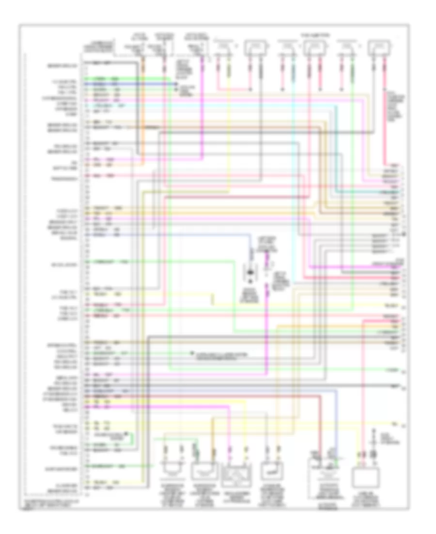
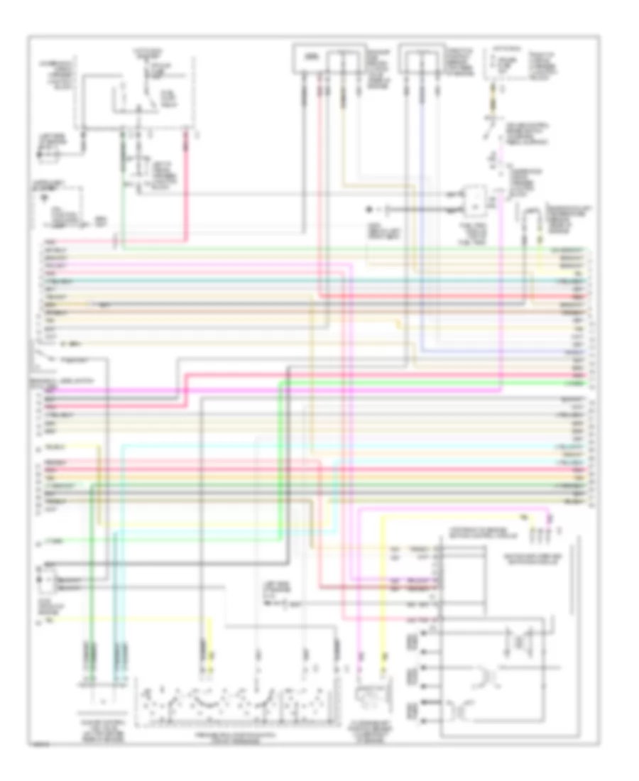
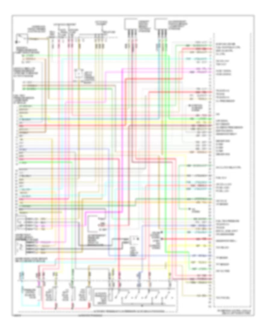
3.1L 3.1L (VIN M), Engine Performance Wiring Diagrams (1 of 3) for Oldsmobile Cutlass GL 1998 List of elements for 3.1L (VIN M), Engine Performance Wiring Diagrams (1 of 3) for Oldsmobile Cutlass GL 1998: 65 (left side of dash) 1-2 valve ctrl 2-3 valve ctrl 3x ref high 3x ref low 5v ref A/t iss sensor high A/t iss sensor low Automatic transaxle Automatic transaxle input shaft speed sensor Batt voltage Brake sw input Bypass control Ckp sensor Cmp sensor signal Cooling fans system Cruise control system Cruise disable Data link connector Egr sol valve Evap canp driver Evaporative emission canister purge valve (top rear of engine) Evaporative emission canister vent solenoid (under rear of vehicle) Fan 1 ctrl Fan 2 ctrl Fuel inj 1 Fuel inj 2 Fuel inj 3 Fuel inj 5 Fuel injectors G125 (front of engine) Ho2s 1 low Ho2s 2 low Hot at all times Hot in accy, run or start Hot in run or start Iac coil b high Ic control Ign Ign mod fuse 10a Inj 6 driver Instrument cluster system (vehicle speed signal) Intake air temperature (iat) sensor (in air intake duct, near throttle body) Knock sensor (left side of engine) Ks signal Left i/p wiring harness junction block Left i/p wiring harness junction c1 block Maf sensor Mass air flow sensor (on air intake duct assembly) Pcm batt fuse 10a Pcm ground Pnk Powertrain control module (below left side of dash) Prndl fuse 10a S101 (injector harness, 16 cm from in-line connec- tor) Sensor ground Serial data Tan Tr sw input b Trans range a Underhood wiring harness junction block Vehicle speed sensor (on transaxle) Vss high Vss low Vss output 3.1L (VIN M), Engine Performance Wiring Diagrams (2 of 3) for Oldsmobile Cutlass GL 1998 List of elements for 3.1L (VIN M), Engine Performance Wiring Diagrams (2 of 3) for Oldsmobile Cutlass GL 1998: 32 (left side of engine) g112 (top front of engine) ignition control module 7x crankshaft position sensor (lower right of engine) B11 Cruise control brake switch (on brake pedal support) Cruise fuse 10a Engine coolant temperature sensor (rear of engine) Engine oil level switch (in oil pan) Exhaust gas recirc- ulation valve (rear of engine) F/p injr fuse 15a Fuel pump relay Fuel tank module (top of fuel tank) G125 (front of engine) G300 (below left front seat) Hot in run Hot in run or start Idle air control (iac) valve (on top center rear of engine) Ign Ignition amplifier and switching module Instrument cluster Left i/p wiring harness junction block Mal- function indicator lamp Park/neutral position switch (top of transaxle) Plugs spark Pnk Red Right i/p wiring harness junction block Spark plugs Tan Throttle position sensor (top rear of engine) Underhood wiring harness junction block Underhood wiring harness junction block c1 3.1L (VIN M), Engine Performance Wiring Diagrams (3 of 3) for Oldsmobile Cutlass GL 1998 List of elements for 3.1L (VIN M), Engine Performance Wiring Diagrams (3 of 3) for Oldsmobile Cutlass GL 1998: 73 2-3 shift sole- noid valve 24x crankshaft position sensor (lower front of engine) 5v ref A/c clutch relay ctrl A/c refrig pres sensor A/c refrigerant pressure sensor (front of engine compt) A/c system Auto trans fuse 10a Automatic transaxle Automatic transaxle fluid pressure valve manual pos switch Automatic transaxle fluid temp sensor C11 Camshaft position sensor (top front of engine) Cruise control system Cruise engaged Ect densor Egr pos signal Egr valve ctrl Eng oil level input Engine oil pressure sensor (left side of engine) Erls fuse 20a Evap canv driver Fuel inj 4 Fuel pump relay ctrl Fuel tank pressure Fuel tank pressure sensor (under rear of vehicle) G202 (left side of dash) Generator term f Generator term l Heated front oxygen sensor (top rear of engine) Heated rear oxygen sensor (below center of vehicle) Ho2s 1 signal Ho2s 2 signal Hot in run or start Iac coil a hi Iac coil a low Iac coil b Iat sensor Ign Ign voltage Left i/p wiring harness junction block Manifold absolute pressure sensor (attached to bracket on top of engine) Map signal Mil ctrl Nca Oil pres sensor Pc sol high Pc sol low Pcm/ign fuse 10a Pnk Pnk e Pnk n Powertrain control module (below left side of dash) Pressure control solenoid valve Red Red p Red/ Sensor gnd Start- ing/ charging system Starting/ charging system Tach out Tach test point Tan Tcc pwm sol Tcc pwm sole- noid valve Tcc rel sw Tft sensor Tp sensor Tr sw b Tr switch a Tr switch c Tr switch d Underhood wiring harness junction block
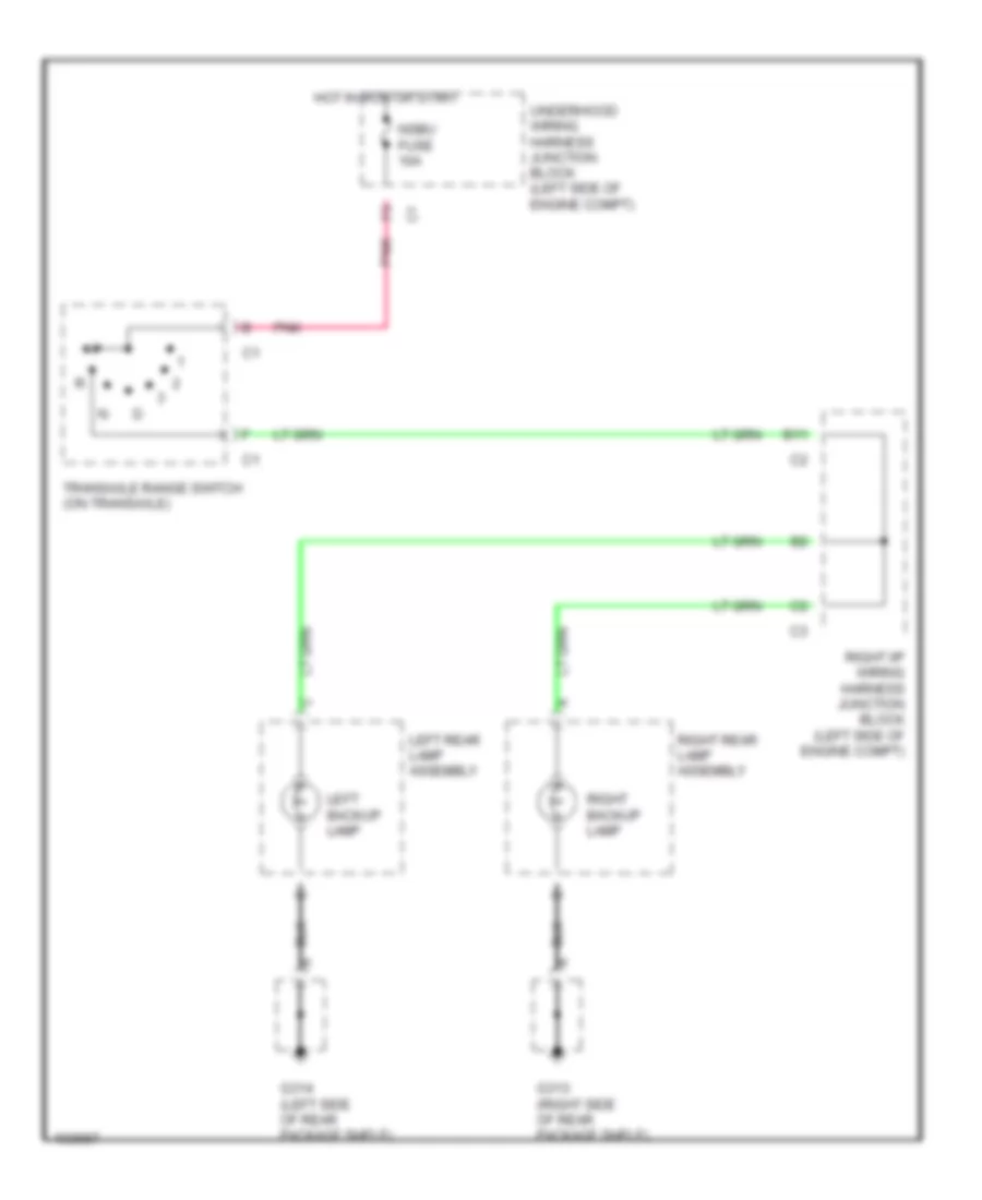
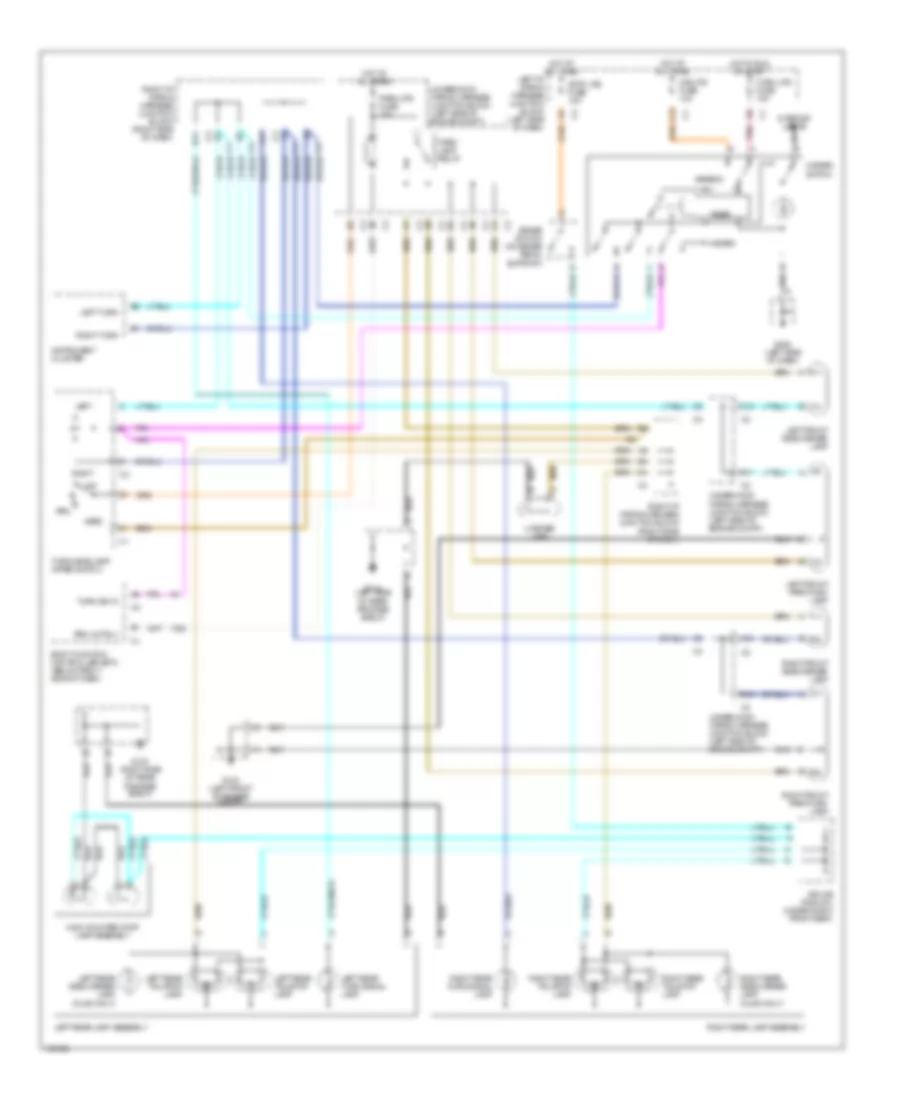
EXTERIOR LIGHTS Backup Lamps Wiring Diagram for Oldsmobile Cutlass GL 1998 List of elements for Backup Lamps Wiring Diagram for Oldsmobile Cutlass GL 1998: 13 B11 G313 (right side of rear package shelf) G314 (left side of rear package shelf) Hot in run or start Left backup lamp Left rear lamp assembly Nsbu fuse 10a Pnk Right backup lamp Right i/p wiring harness junction block (left side of engine compt) Right rear lamp assembly Transaxle range switch (on transaxle) Underhood wiring harness junction block (left side of engine compt) Exterior Lamps Wiring Diagram for Oldsmobile Cutlass GL 1998 List of elements for Exterior Lamps Wiring Diagram for Oldsmobile Cutlass GL 1998: 53 A10 A11 B10 B11 Body function controller (bfc) (below right side of dash) Brake switch (on brake pedal support) C10 C12 G100 (left front of engine compt) G202 (left side of dash) G313 (right side of rear package shelf) G314 (left side of rear package shelf) Haz lps fuse 10a Hazard Hazard switch Head High mounted stop lamp assembly Hot at all times Hot in run or start Instrument cluster Interior lights Left Left front park/turn lamp Left front side marker lamp Left i/p wiring harness junction block (left side of dash) Left rear lamp assembly Left rear side marker lamp (olds only) Left rear tail/stop lamp Left rear turn signal lamp Left turn License lamp Off Park lamp relay Park lps fuse 15a Pnk Prk Prk lmp rly Right Right front park/turn lamp Right front side marker lamp Right i/p wiring harness junction block (right side of dash) Right rear lamp assembly Right rear side marker lamp (olds only) Right rear tail/stop lamp Right rear turn signal lamp Right turn Splice pack 301 (under right front seat) Stop lps fuse 15a Timer Turn lps fuse 10a Turn sig in Turn/headlamp/ wiper switch Underhood wiring harness junction block (left side of engine compt)
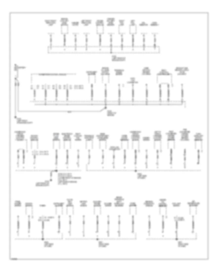
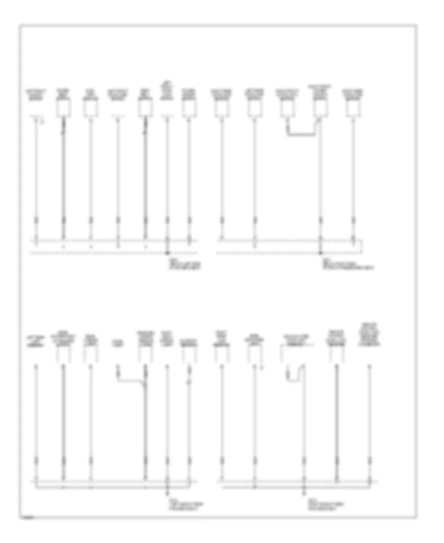
GROUND DISTRIBUTION Ground Distribution Wiring Diagram (1 of 2) for Oldsmobile Cutlass GL 1998 List of elements for Ground Distribution Wiring Diagram (1 of 2) for Oldsmobile Cutlass GL 1998: 59 (2.4l vin t) (3.1l vin m) (chevy) (olds) (olds) (chevy) A10 Air temperature actuator Ashtray lamp (chevy) Auxiliary power outlet B10 Battery Blower motor Body function controller Brake fluid level switch Brake transaxle shift interlock solenoid Cigar lighter Cruise control module D10 Data link connector Drl resistor Electronic brake control module Engine coolant level switch Engine oil level switch (3.1l vin m) Exhaust gas recirculation valve (2.4l vin t) Fog lamp switch G100 (left front of engine compt) G125 (2.4l vin t) g112 (3.1l vin m) (lower front of engine) (2.4l vin t) (left side of engine) (3.1l vin m) G125 (front of engine) G201 (right side of dash) G202 (left side of dash) Glove box lamp/ switch Hazard switch Heater a/c control assembly Horn assembly Ignition control module Ignition switch Instrument cluster Left fog lamp Left front park/turn lamp Left i/p wiring harness junction block Mass air flow sensor (3.1l vin m) Nca c Panel dimmer switch Post converter heated oxygen sensor Powertrain control module Pre converter heated oxygen sensor (3.1l vin m) Radio Rear compartment lid release switch Right cooling fan motor Right fog lamp Right front park/turn lamp Sensing diagnostic module Transaxle indicator lamp Transaxle range switch Turn/ headlamp switch assembly Underhood wiring harness junction block Washer motor Washer solvent level sensor Wiper motor assembly Ground Distribution Wiring Diagram (2 of 2) for Oldsmobile Cutlass GL 1998 List of elements for Ground Distribution Wiring Diagram (2 of 2) for Oldsmobile Cutlass GL 1998: 28 Dome lamp Fuel tank module G300 (below left side of driver's seat) G301 (below right side of front passenger's seat) G313 (right side of rear package shelf) G314 (left side of rear package shelf) High mounted stop lamp assembly Left front door ajar switch Left front door lock switch Left front window switch Left rear door ajar switch Left rear lamp assembly Nca Power mirror switch Power seat switch Rear compartment lid release motor Rear defogger grid Rear license lamp Rearview mirror reading lamps Remote control door lock receiver Remote control door lock receiver program connector Right front door lock switch Right front power window switch Right rear door ajar switch Right rear lamp assembly Right vanity mirror lamp Seat belt switch Sunroof assembly
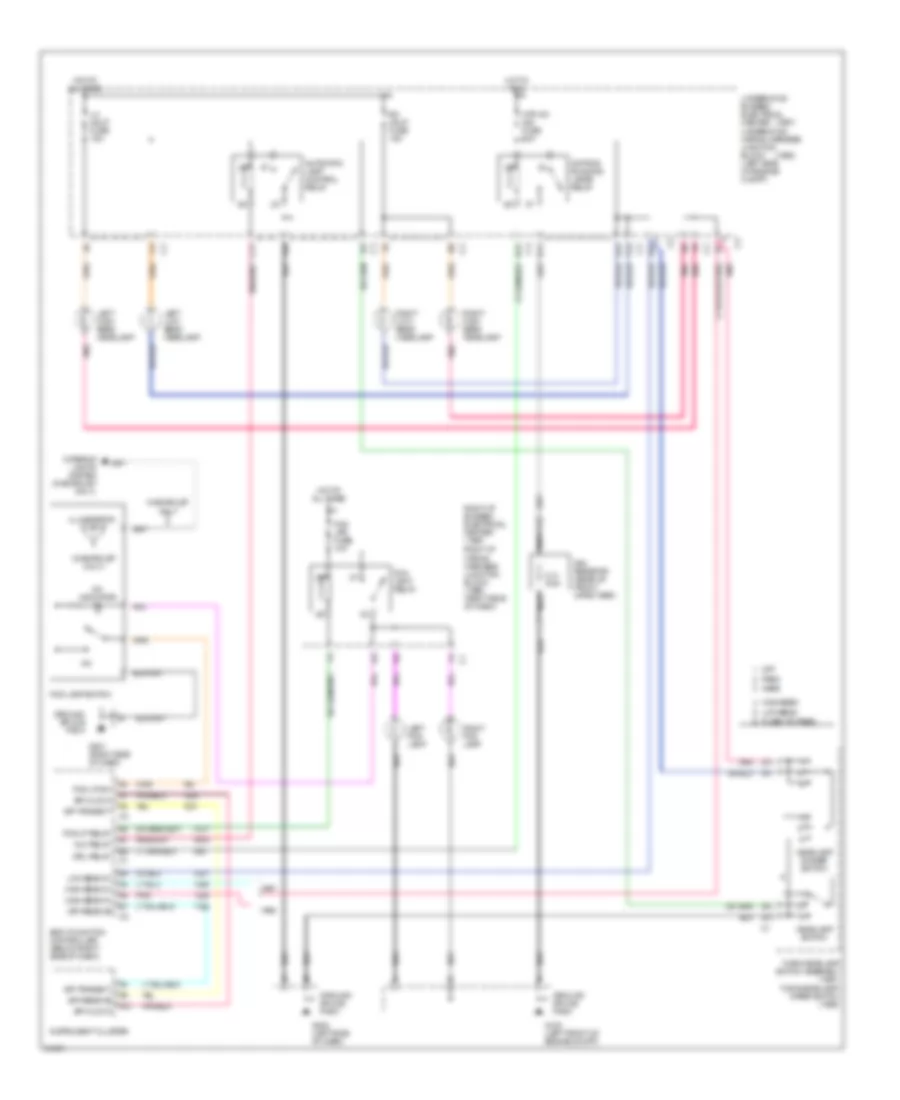
HEADLIGHTS Headlamps/Fog Lamps Wiring Diagram for Oldsmobile Cutlass GL 1998 List of elements for Headlamps/Fog Lamps Wiring Diagram for Oldsmobile Cutlass GL 1998: 67 (1997) (1998) (chevrolet only) 0.31 ohm A10 A12 Alc relay Automatic lamp control relay B12 c3 B3 c3 Body function controller (below right side of dash) C11 C4 c2 Chevrolet only D11 Daytime running lamps relay Drl relay Drl resistor (rear of front impact bar) E12 E8 c2 F12 c2 F4 c1 F6 c2 Flash-to-pass Fog lamp relay Fog lamp switch Fog lp relay Fog lp sw Fog lps fuse 10a G100 (left front of engine compt) G201 (right side of dash) G202 (left side of dash) Ground splice pack Head Headlamp dimmer switch Headlamp switch High beam High beam in Hot at all times Hot in run Htr a/c ign fuse 10a Illumination Instrument cluster Interior lights system (chevrolet only) Left fog lamp Left high beam headlamp Left low beam headlamp Lh hdlp fuse 15a Low beam Low beam in Nca Off On indicator Park Pnk Rh hdlp fuse 15a Right fog lamp Right high beam headlamp Right i/p bussed electrical center (1997) Right i/p wiring harness junction block (1998) (right side of dash) Right low beam headlamp Spi clock Spi receive Spi transmit Turn/headlamp switch assembly (1997) turn/headlamp/ wiper switch (1998) Underhood bussed electrical center Underhood wiring harness junction block (left side of engine compt)
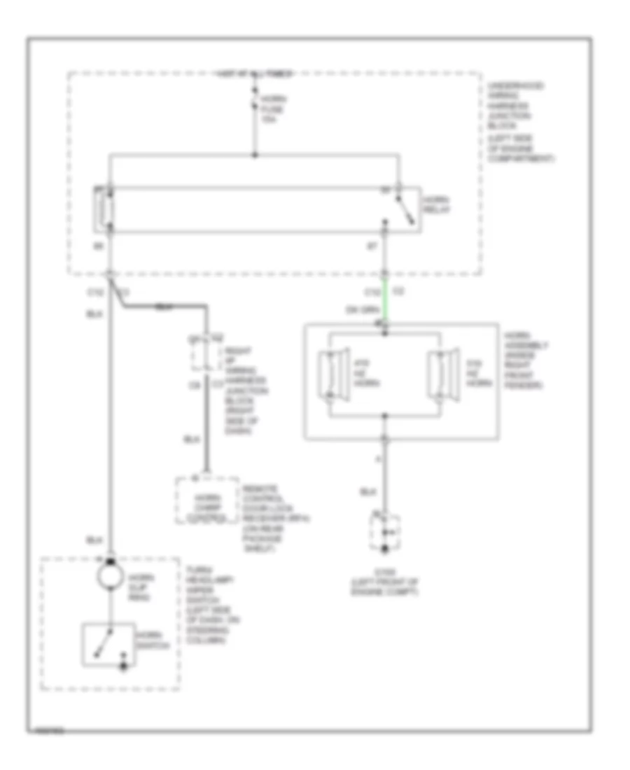
HORN Horn Wiring Diagram for Oldsmobile Cutlass GL 1998 List of elements for Horn Wiring Diagram for Oldsmobile Cutlass GL 1998: 15 (left side of engine compartment) C12 G100 (left front of engine compt) Horn assembly (inside right front fender) Horn chirp control Horn fuse 15a Horn relay Horn slip ring Horn switch Hot at all times Hz horn Remote control door lock receiver (rfa) (on rear package shelf) Right i/p wiring harness junction block (right side of dash) Turn/ headlamp/ wiper switch (left side of dash, on steering column) Underhood wiring harness junction block
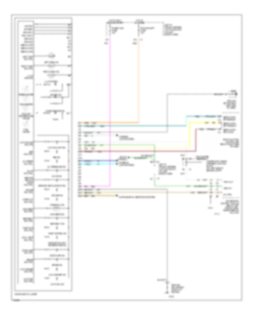
INSTRUMENT CLUSTER Instrument Cluster Wiring Diagram for Oldsmobile Cutlass GL 1998 List of elements for Instrument Cluster Wiring Diagram for Oldsmobile Cutlass GL 1998: 79 service vehicle soon ind (2.4l) (3.1l) A10 A11 A12 Abs ind Abs ind ctrl Air bag ind B10 B11 B12 Battery Body function controller (below right side of dash) Brake ind Brake ind ctrl Check engine ind Check oil ind Check oil ind ctrl Cool temp ind ctrl Coolant temperature gauge Cruise ind Cruise ind ctrl Door ajar ind Door ajar ind ctrl Engine coolant temperature ind Exterior lights system Fuel gauge G125 G202 Ground Ground splice pack (front of engine) Ground splice pack (left side of dash) High beam ind High beam ind ctrl Hot at all times Hot in accy, run and start Ignition Illum ground Illumination Instrument cluster Interior lights system Ipc/bfc acc fuse 10a Ipc/hvac batt fuse 10a Left i/p wiring harness junction block (on left side of dash) Left turn ind Left turn ind ctrl Low coolant ind Low coolant ind ctrl Low fuel ind Low fuel ind ctrl Low washer ind Low washer ind ctrl Mil ctrl Oil press ind ctrl Oil pressure ind Powertrain control module (below left side of dash, near steering column) Right turn ind Right turn ind ctrl Seat belt ind Seat belt ind ctrl Serial data Serial data spi clock Serial data spi receive Serial data spi transmit Service vehicle soon ind ctrl Sound systems Speedometer Tach input Tach out Tachometer Tachometer test point Theft sys ind ctrl Theft system ind Underhood wiring harness junction block (on left side of engine compt) Volts ind Volts ind ctrl Vss input Vss out
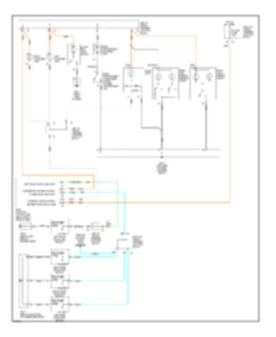
INTERIOR LIGHTS Courtesy Lamps Wiring Diagram for Oldsmobile Cutlass GL 1998 List of elements for Courtesy Lamps Wiring Diagram for Oldsmobile Cutlass GL 1998: 37 (below left side of driver's seat) (below right side of passenger's seat) A11 A12 B10 Battery positive voltage Body function controller (below right side of dash) C10 Dome lamp Door G201 (right side of dash) G300 G301 G314 (left side of rear package shelf) Glove box lamp/ switch Hot at all times Inadvertant power control Int lps fuse 10a Interior lamps control Left courtesy lamp Left front door ajar input Left front door ajar switch Left i/p wiring harness junction block Left rear door ajar switch Off Other door ajar input Rear compartment courtesy lamp Rear compartment lid release motor (in rear compartment lid) Rear view mirror reading lamps Remote control door lock receiver Right courtesy lamp Right front door ajar switch Right i/p wiring harness junction block Right rear door ajar switch Right vanity mirror lamps Secondary latch Unlatch Instrument Illumination Wiring Diagram for Oldsmobile Cutlass GL 1998 List of elements for Instrument Illumination Wiring Diagram for Oldsmobile Cutlass GL 1998: 43 (5 bulbs) (chevy) (olds) A12 Ashtray lamp B12 C12 Chevrolet E11 E12 E16 F12 Fog lamp switch From right i/p bussed a electrical center (diagram 1 of 1) G201 (right side of dash) G202 (left side of dash) G300 (below left side of front driver's seat) G301 (below right side of front passenger's seat) G314 (left side of rear package shelf) Hazard switch Head Heater a/c control assembly Hot at all times Inst lamps fuse 10a Instrument cluster Lamp dimmer module (on left side of dash) Left front door lock switch Left front power window switch Off Panel dimmer switch Park Park lps fuse 15a Power mirror switch Power sunroof switch assembly Radio Rear compartment lid release switch Right front door lock switch Right front power window switch Right i/p wiring harness junction block To right i/p bussed electrical center (diagram 1 of 1) Transaxle indicator lamp Turn/ headlamp/ wiper switch Wiring harness junction block
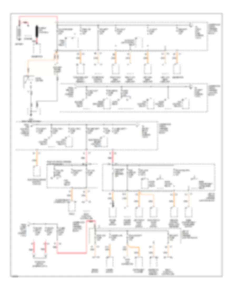
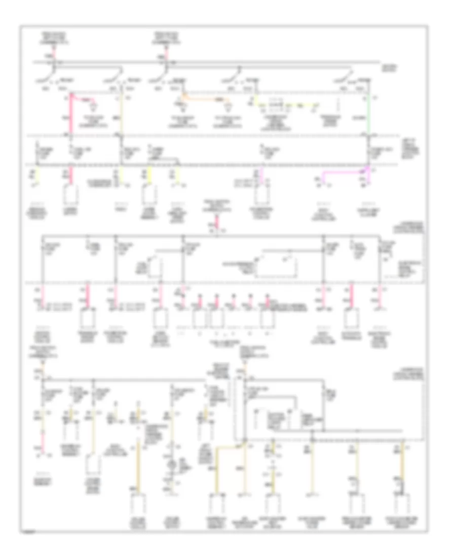
POWER DISTRIBUTION Power Distribution Wiring Diagram (1 of 2) for Oldsmobile Cutlass GL 1998 List of elements for Power Distribution Wiring Diagram (1 of 2) for Oldsmobile Cutlass GL 1998: 88 (chevrolet) (oldsmobile) f1 c10 A nca A11 A12 Automatic lamp control relay Aux pwr/cigar fuse 20a Auxiliary power outlet B10 B11 Battery Bfc batt fuse 10a Blower motor relay Body function controller Brake switch C12 Cigar lighter Cool fan 1 fuse 30a Cool fan 2 fuse 15a Data link connector Door lock relay Door unlock relay Dr lock fuse 15a E12 Electronic brake control module Electronic brake control relay Fan control relay 1 Fan control relay 2 Fog lamps relay Fog lps fuse 10a From a gen bat fuse (diagram 1 of 2) From b fan control relay 2 (diagram 1 of 2) From c lh bec batt 1 fuse (diagram 1 of 2) G201 (right side of dash) Gen batt fuse 10a Generator Hazard lps fuse 10a Hazard switch Heater-a/c control assembly Hi blo mot fuse 30a Horn fuse 15a Horn relay Icc batt fuse 10a Icc fuse 40a Ign-sw batt 1 fuse 40a Ign-sw batt 2 fuse 30a Instrument cluster Int lps fuse 10a Ipc/hvac batt fuse 10a Left front door lock switch Left high beam headlamp Left i/p wiring harness junction block Left low beam headlamp Lh bec batt 1 fuse 40a Lh bec batt 2 fuse 30a Lh hdlp fuse 15a Mode control relay Park lamp relay Park lps fuse 15a Pcm batt fuse 10a Power mirror switch Power seat switch Powertrain control module Pwr mirror fuse 10a Pwr seat circuit breaker 25a Radio Rdo batt fuse 10a Rear compartment lid release relay Rear compartment lid release switch Rear defogger relay Red Remote control door lock receiver Rh bec batt fuse 30a Rh hdlp fuse 15a Right front door lock switch Right high beam headlamp Right i/p wiring harness junction block Right low beam headlamp Rr defog fuse 30a Starter Stop lps fuse 15a To hi blo mot fuse (diagram 1 of 2) To icc batt fuse (diagram 1 of 2) To ign-sw bstt 2 fuse (diagram 1 of 2) To ignition switch (diagram 2 of 2) Trunk rel/rfa fuse 10a Turn/headlamp switch assembly Underhood wiring harness junction block Power Distribution Wiring Diagram (2 of 2) for Oldsmobile Cutlass GL 1998 List of elements for Power Distribution Wiring Diagram (2 of 2) for Oldsmobile Cutlass GL 1998: 78 (2.4l vin t) (3.1l vin m) (oldsmobile) (chevrolet) A/c bfc fuse 10a A/c compressor clutch relay A11 A12 Acc Air bag fuse 10a Air temperature actuator Auto trans fuse 10a Automatic transaxle B l Body function controller C11 Cruise control brake switch Cruise control module Cruise control switch Cruise fuse 10a Cruise sw fuse 2a Daytime running lamps relay Electronic brake control module Electronic brake control relay Erls fuse 10a Evap canister purge valve Evap canister vent solenoid F/p injr fuse 15a F11 F2 c9 From ign sw- batt 1 fuse (diagram 1 of 2) From ign sw- batt 2 fuse (diagram 1 of 2) From ignition switch (diagram 2 of 2) Fuel injectors (3.1l vin m) Fuel pump relay Hazard switch Heater-a/c control assembly Htr a/c ign fuse 10a Hvac blower fuse 20a Icc ign fuse 10a Ign mod fuse 10a Ignition control module Ignition switch Instrument cluster Ipc/bfc acc fuse 10a Left front power window switch Left i/p wiring harness junction block Lock Mass air flow sensor (3.1l vin m) Nca Nsbu fuse 10a Pcm acc fuse 10a Pcm ign fuse 10a Pnk Post-converter heated oxygen sensor Powertrain control module Pre-converter heated oxygen sensor Pwr wndws circuit breaker 25a Radio Rdo acc fuse 10a Rear defogger relay Red Right i/p bussed electrical center Run S101 (injector harness, top rear of engine) Sensing diagnostic module Sir coil assem- bly Start Sunroof assembly Sunroof fuse 20a To htr a/c ign fuse (diagram 2 of 2) To ign mod fuse (diagram 2 of 2) To sunroof fuse (diagram 2 of 2) Transaxle range switch Turn lps fuse 10a Turn/ headlamp/ wiper switch Underhood wiring harness junction block Wiper fuse 25a Wiper motor assembly
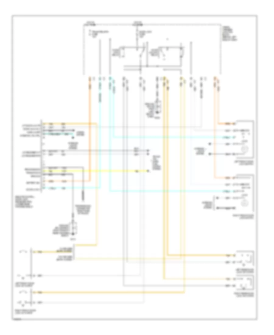
POWER DOOR LOCKS Power Door Lock Wiring Diagram for Oldsmobile Cutlass GL 1998 List of elements for Power Door Lock Wiring Diagram for Oldsmobile Cutlass GL 1998: 40 (w/ rke) A11 Battery (b+) Door lk rly Door lock fuse 15a Door lock relay Door unlk rly Door unlock relay E10 G202 G313 Ground Ground splice pack (left end of dash) Ground splice pack (right side of rear package shelf) Horn chirp Horns system Hot at all times Interior lights system Interior lts ctrl Left front door lock actuator Left front door lock switch Left rear door lock actuator Lft door lk mtr Lid release out Lid release pwr Lock Programming Programming connector (right side of trunk) Remote control door lock receiver (rfa) (under rear package shelf) Right front door lock actuator Right front door lock switch Right rear door lock actuator Tan Trans pos in Trunk rel/rfa fuse 10a Trunk/ tail- gate/ fuel doors system Unlock W/ keyless entry system W/o keyless entry system Wiring harness junction block (behind left side of dash)
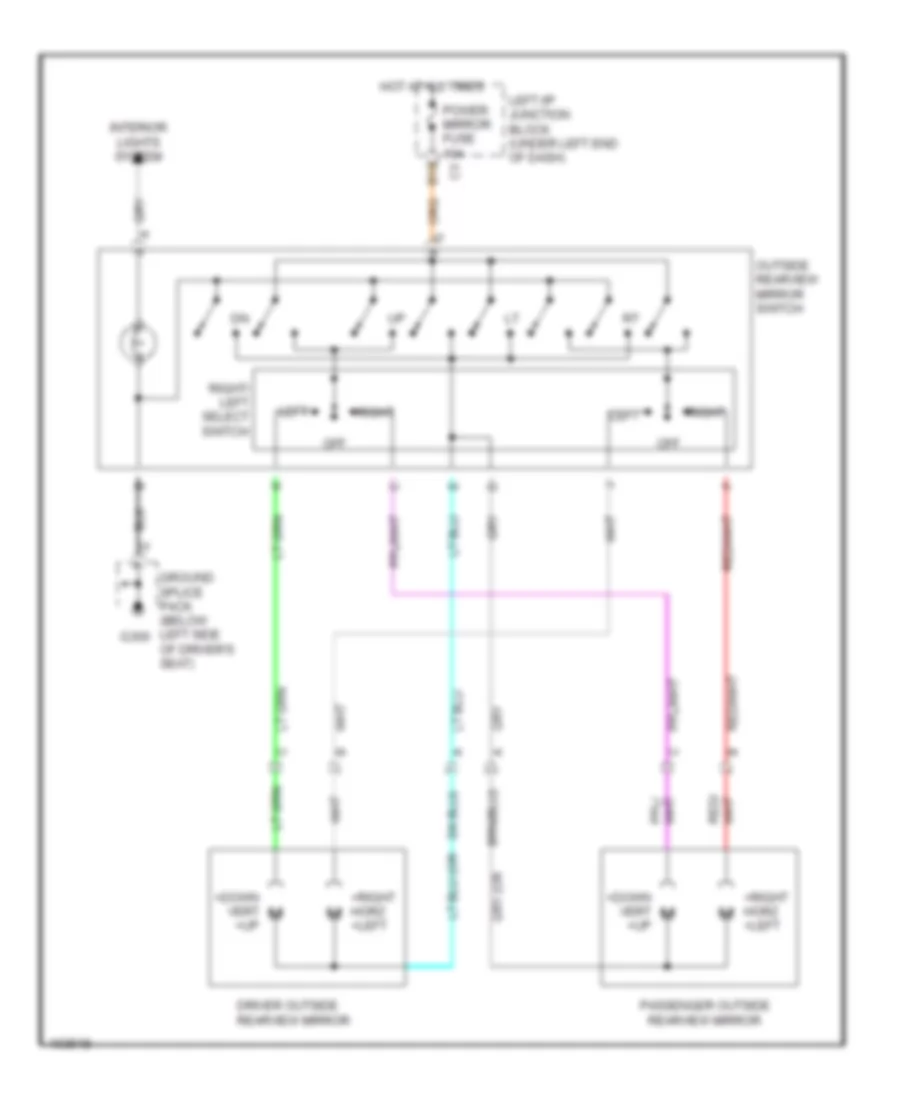
POWER MIRRORS Power Mirror Wiring Diagram for Oldsmobile Cutlass GL 1998 List of elements for Power Mirror Wiring Diagram for Oldsmobile Cutlass GL 1998: 16 +down vert +up +right horz +left B10 Driver outside rearview mirror G300 Ground splice pack (below left side of driver's seat) Hot at all times Interior lights system Left Left i/p junction block (under left end of dash) Off Outside rearview mirror switch Passenger outside rearview mirror Power mirror fuse 10a Right Right/ left select switch
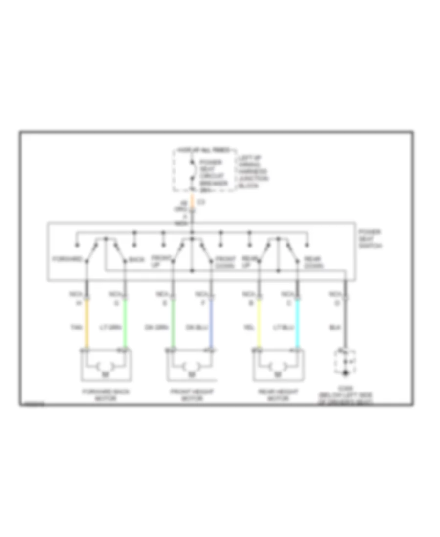
POWER SEATS 6-Way Power Seat Wiring Diagram for Oldsmobile Cutlass GL 1998 List of elements for 6-Way Power Seat Wiring Diagram for Oldsmobile Cutlass GL 1998: 16 Back Forward Forward back motor Front down Front height motor Front up G300 (below left side of driver's seat) Hot at all times Left i/p wiring harness junction block Nca Power seat circuit breaker 25a Power seat switch Rear down Rear height motor Rear up Tan
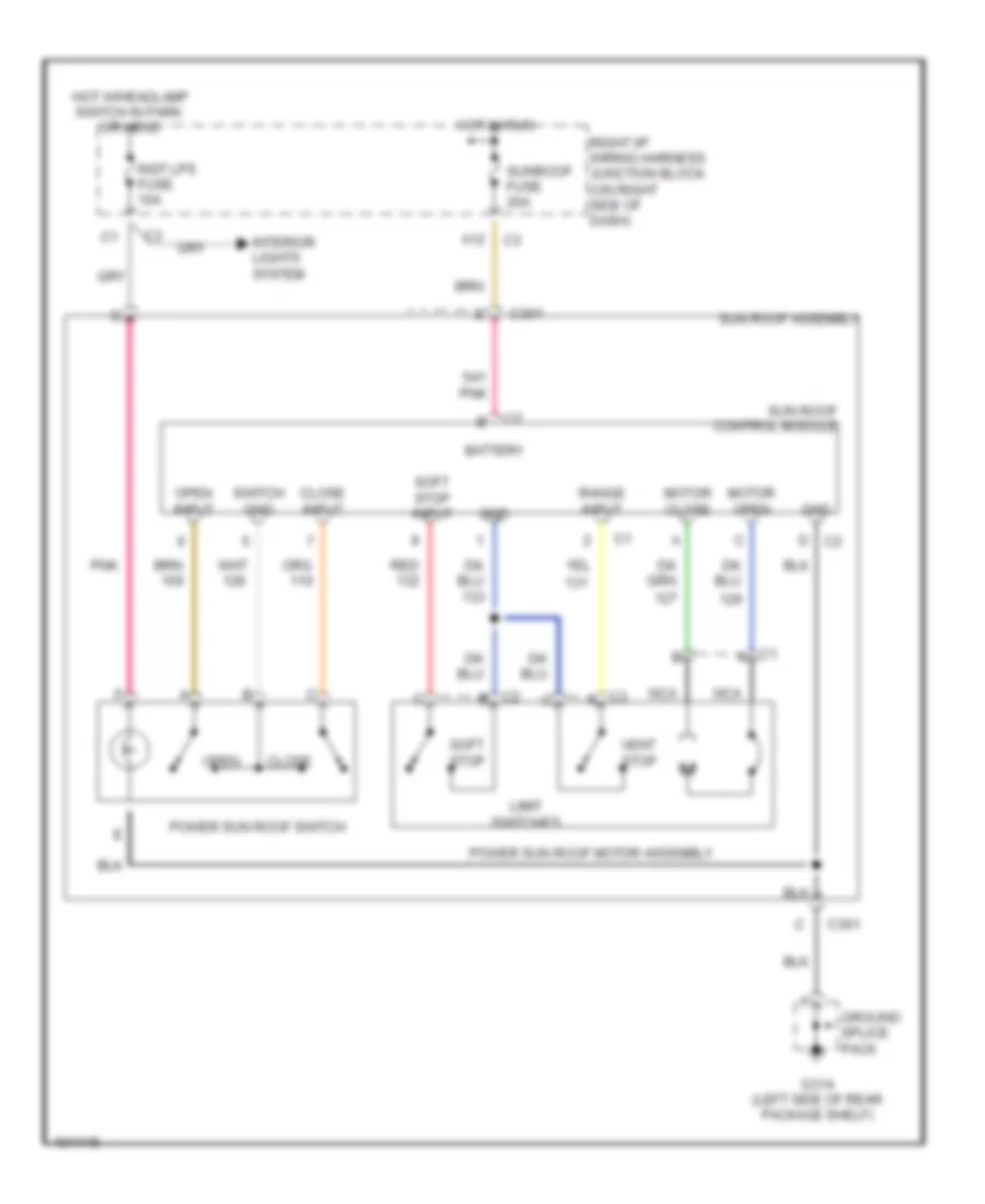
POWER TOP/SUNROOF Power Top/Sunroof Wiring Diagrams for Oldsmobile Cutlass GL 1998 List of elements for Power Top/Sunroof Wiring Diagrams for Oldsmobile Cutlass GL 1998: 31 A12 Battery C301 Close Close input G314 (left side of rear package shelf) Gnd Ground splice pack Hot in run Hot w/headlamp switch in park or head Inst lps fuse 10a Interior lights system Limit switches Motor close Motor open Nca Open Open input Pnk Power sun roof motor assembly Power sun roof switch Range input Red Right i/p wiring harness junction block (on right side of dash) Soft stop Soft stop input Sun roof assembly Sun roof control module Sunroof fuse 20a Switch gnd Vent stop
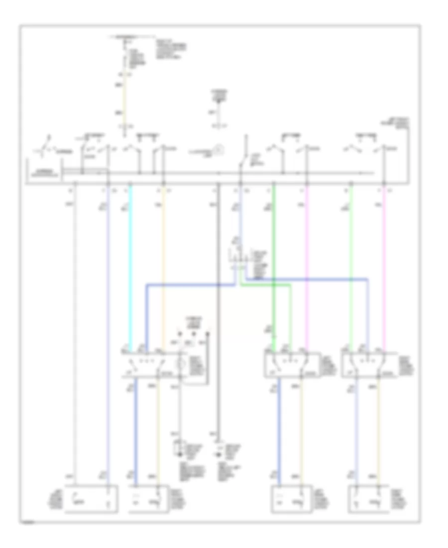
POWER WINDOWS Power Window Wiring Diagram for Oldsmobile Cutlass GL 1998 List of elements for Power Window Wiring Diagram for Oldsmobile Cutlass GL 1998: 28 Down Ecb Express Express down module G300 (below left side of driver's seat) G301 (below right side of front passenger's seat) Ground splice pack g300 Ground splice pack g301 Hot in run Illumination lamp Interior lights system Left front Left front power window motor Left front power window switch Left rear Left rear power window motor Left rear power window switch Lock out switch Pwr wndws circuit breaker 25a Right front Right front power window motor Right front power window switch Right i/p wiring harness junction block (on right side of dash) Right rear Right rear power window motor Right rear power window switch Splice pack s301 (under right front seat) Tan
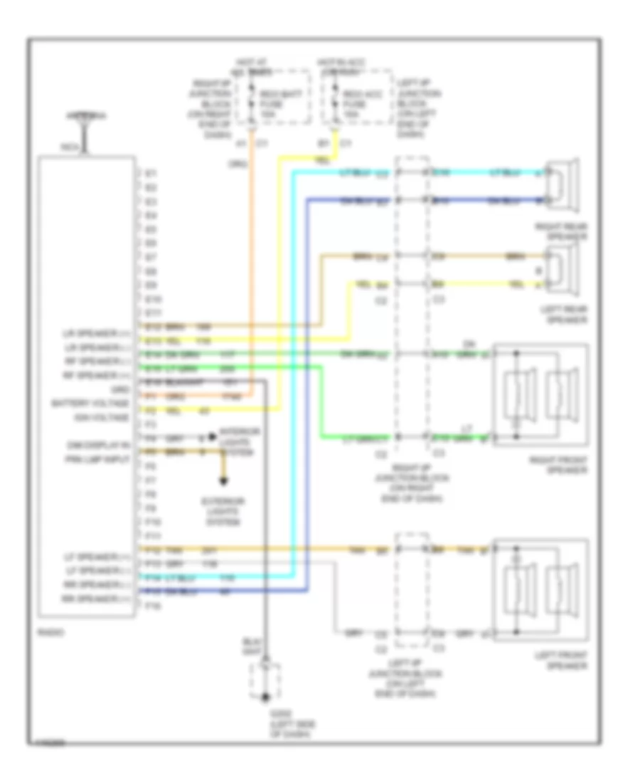
RADIO Radio Wiring Diagrams for Oldsmobile Cutlass GL 1998 List of elements for Radio Wiring Diagrams for Oldsmobile Cutlass GL 1998: 50 A10 Antenna B1 c1 B10 Battery voltage C1 a1 C10 C12 Dim display in E10 E11 E12 E13 E14 E15 E16 Exterior lights system F10 F11 F12 F13 F14 F15 F16 G202 (left side of dash) Grd Hot at all times Hot in acc or run Ign voltage Interior lights system Left front speaker Left i/p junction block (on left end of dash) Left rear speaker Lf speaker (+) Lf speaker (-) Lr speaker (+) Lr speaker (-) Nca Prk lmp input Radio Rdo acc fuse 10a Rdo batt fuse 10a Rf speaker (+) Rf speaker (-) Right front speaker Right i/p junction block (on right end of dash) Right rear speaker Rr speaker (+) Rr speaker (-) Tan
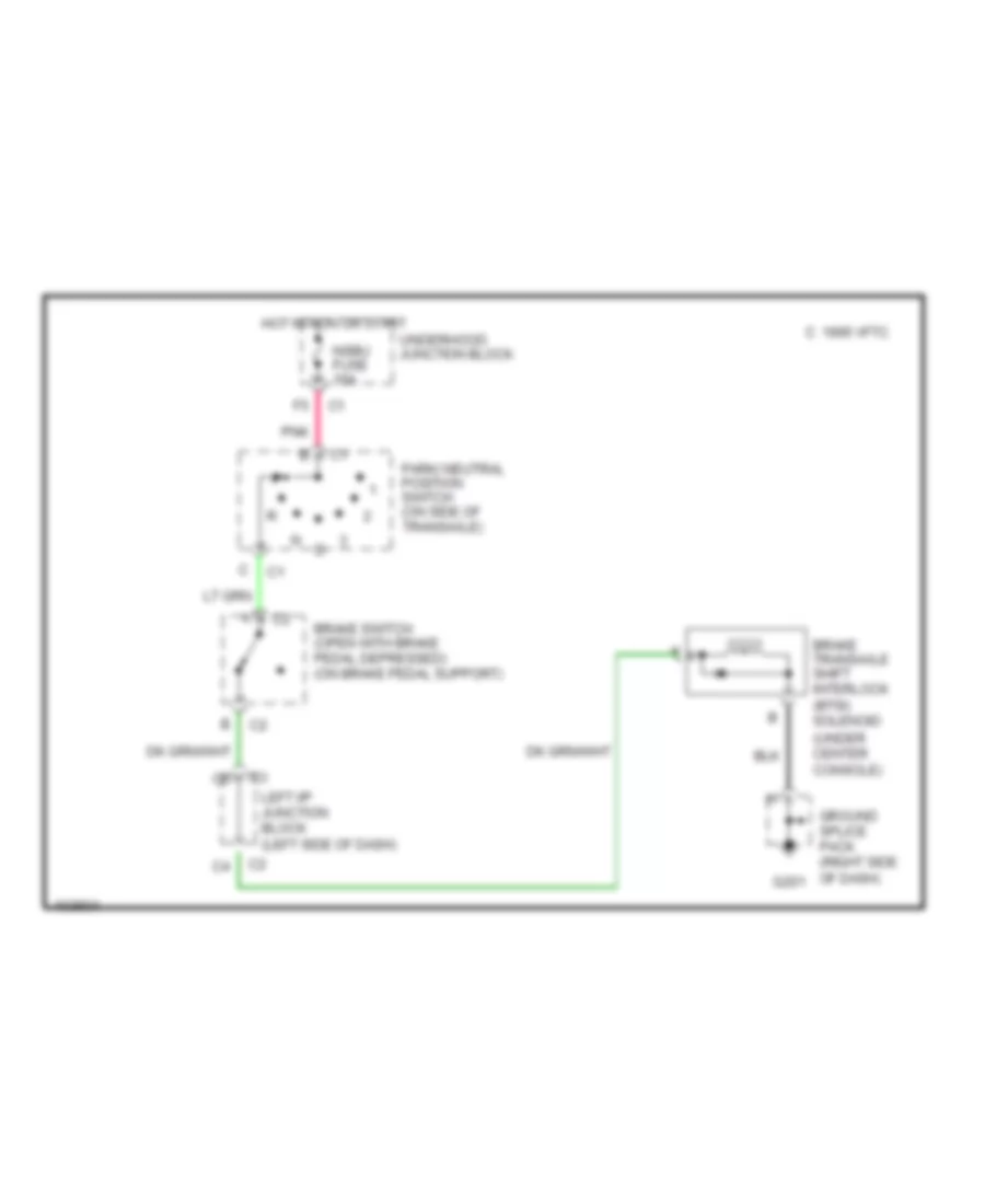
SHIFT INTERLOCKS Shift Interlock Wiring Diagram for Oldsmobile Cutlass GL 1998 List of elements for Shift Interlock Wiring Diagram for Oldsmobile Cutlass GL 1998: 12 (under center console) 1995 vftc c Brake switch (open with brake pedal depressed) (on brake pedal support) Brake transaxle shift interlock (btsi) solenoid G201 Ground splice pack (right side of dash) Hot in run or start Left i/p junction block (left side of dash) Nsbu fuse 10a Park/ neutral position switch (on side of transaxle) Pnk Underhood junction block
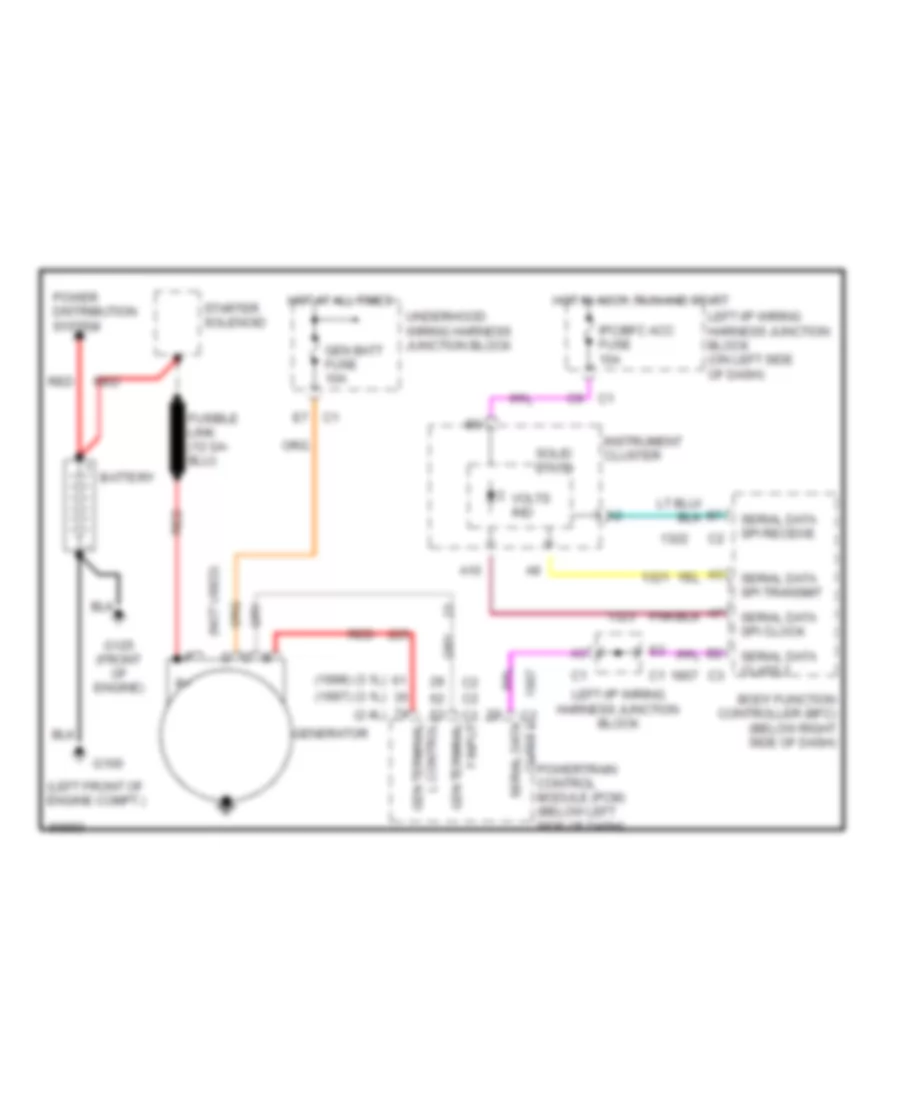
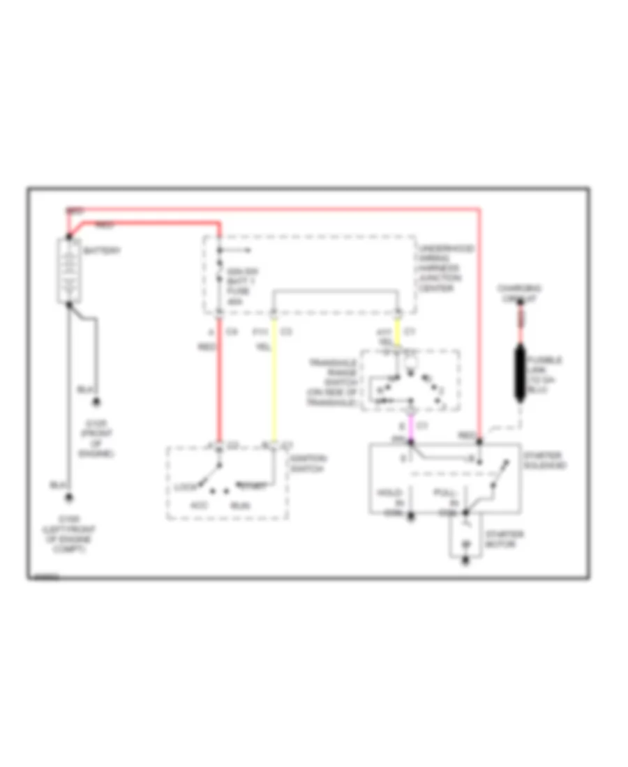
STARTING/CHARGING Charging Wiring Diagram for Oldsmobile Cutlass GL 1998 List of elements for Charging Wiring Diagram for Oldsmobile Cutlass GL 1998: 33 (1997) (3.1l) (1998) (3.1l) (2.4l) (left front of engine compt.) (not used) p A10 Battery Body function controller (bfc) (below right side of dash) C9 c1 E7 c1 F input gen terminal G100 G125 (front of engine) Gen batt fuse 10a Gen terminal l control Generator Hot at all times Hot in accy, run and start Instrument cluster Ipc/bfc acc fuse 10a Left i/p wiring harness junction block Left i/p wiring harness junction block (on left side of dash) Power distribution system Powertrain control module (pcm) (below left side of dash) Red Serial data class 2 Serial data spi clock Serial data spi receive Serial data spi transmit Solid state Starter solenoid Underhood wiring harness junction block Volts ind Starting Wiring Diagram for Oldsmobile Cutlass GL 1998 List of elements for Starting Wiring Diagram for Oldsmobile Cutlass GL 1998: 18 Acc Battery Charging circuit F11 G100 (left front of engine compt) G125 (front of engine) Hold- in coil Ign-sw batt 1 fuse 40a Ignition switch Lock Pull- in coil Red Run Start Starter motor Starter solenoid Transaxle range switch (on side of transaxle) Underhood wiring harness junction center
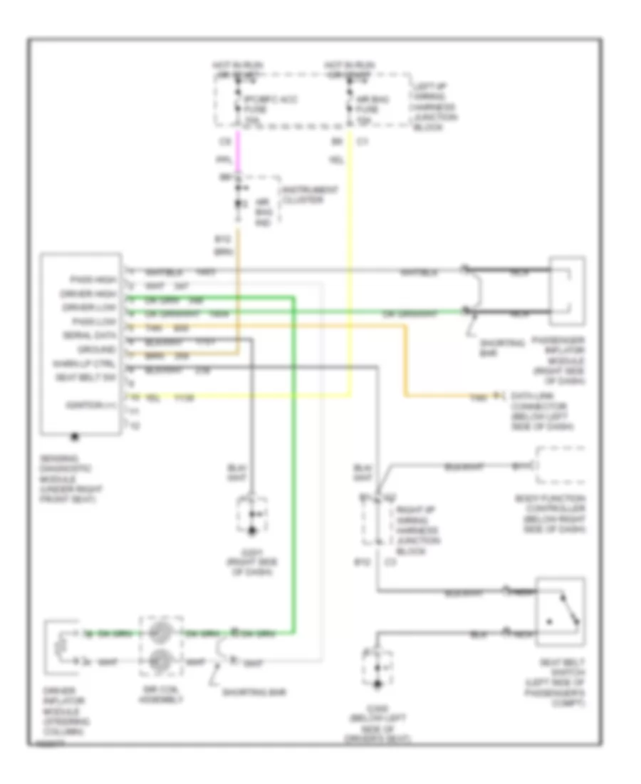
SUPPLEMENTAL RESTRAINTS Supplemental Restraint Wiring Diagram for Oldsmobile Cutlass GL 1998 List of elements for Supplemental Restraint Wiring Diagram for Oldsmobile Cutlass GL 1998: 30 Air bag fuse 10a Air bag ind B11 B12 Body function controller (below right side of dash) Data link connector (below left side of dash) Driver high Driver inflator module (steering column) Driver low G201 (right side of dash) G300 (below left side of driver's seat) Ground Hot in run or start Ignition (+) Instrument cluster Ipc/bfc acc fuse 10a Left i/p wiring harness junction block Nca Pass high Pass low Passenger inflat0r module (right side of dash) Right i/p wiring harness junction block Seat belt sw Seat belt switch (left side of passenger's compt) Sensing diagnostic module (under right front seat) Serial data Shorting bar Sir coil assembly Tan Warn lp ctrl
TRANSMISSION
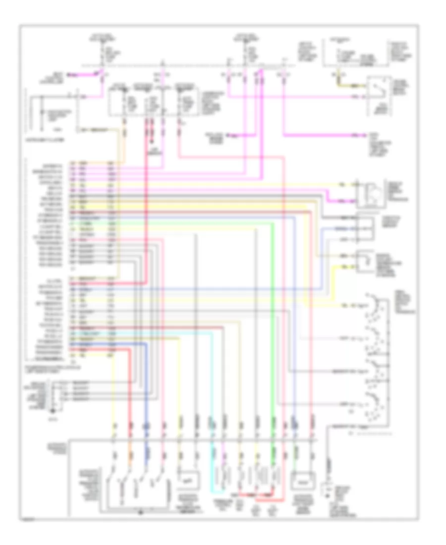
3.1L 3.1L (VIN M), Transmission Wiring Diagram, 4T40-E for Oldsmobile Cutlass GL 1998 List of elements for 3.1L (VIN M), Transmission Wiring Diagram, 4T40-E for Oldsmobile Cutlass GL 1998: 78 1-2 shift sol 2-3 shift sol A/t sensor hi A/t sensor lo Anti-lock brakes system Auto trans fuse 10a Automatic transaxle (4t40-e) Automatic transaxle fluid pressure manual valve position switch Automatic transaxle fluid temperature sensor Automatic transaxle input shaft speed sensor B11 B12 Battery in Body function controller Brake switch in C1 d2 Cruise control brake switch Cruise control system Cruise fuse 10a Data Data class ii Ect return Ect sensor in Engine coolant temperature sensor (top rear of engine) G112 G112 (left side of engine near starter) Gnd Ground splice pack g102 Ground splice pack g102 (left side of engine) near starter) Hot at all times Hot in acc, run or start Hot in run Hot in run or start Ignition (1) in Ignition (2) in Instrument cluster Ipc/ bfc acc fuse 10a Left i/p junction block (left side of dash) Link connector (partial) (left side of dash) Maf sensor Malfunction indicator lamp Mil ctrl P,r,n,lo,d4 Park/ neutral position switch (on transaxle) Pc sol hi Pc sol lo Pcm acc fuse 10a Pcm batt fuse 10a Pcm ground Pcm ign fuse 10a Pnk Powertrain control module (left side of dash) Pressure control sol Red Rev,d,2,1 Right i/p junction block (right side of dash) Tan Tcc pwm sol Tcc release Tcc release in Tcc/ brake switch Tft sensor gnd Tft sensor in Throttle position sensor Tp 5v ref Tp sensor in Tps return Tr sw in-a Tr sw in-b Tr sw in-c Tr sw in-p Trans range a Trans range b Trans range c Underhood junction block (left side of engine compt) Vehicle speed sensor (on transaxle) Vss hi in Vss lo in
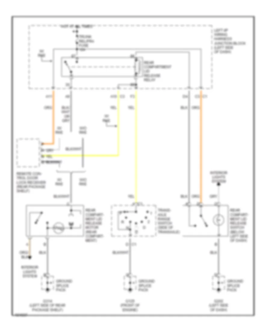
TRUNK, TAILGATE, FUEL DOOR Trunk Release Wiring Diagram for Oldsmobile Cutlass GL 1998 List of elements for Trunk Release Wiring Diagram for Oldsmobile Cutlass GL 1998: 20 A c1 A11 C1 c3 C3 a10 D c1 G125 (front of engine) G202 (left side of dash) G314 (left side of rear package shelf) Ground splice pack Hot at all times Interior lights system Left i/p wiring harness junction block (left side of dash) Rear compart- ment lid release motor (rear compart- ment) Rear compart- ment lid release switch (below left side of dash) Rear compartment lid release relay Remote con- trol door lock receiver (rear package shelf) Trans- axle range switch (side of transaxle) Trunk rel/fra fuse 10a W/ rke W/o rke
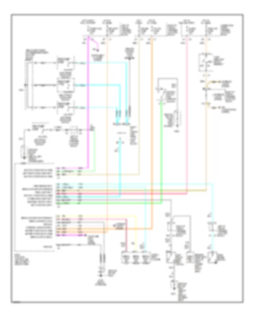
WARNING SYSTEMS Warning System Wiring Diagrams for Oldsmobile Cutlass GL 1998 List of elements for Warning System Wiring Diagrams for Oldsmobile Cutlass GL 1998: 74 (below right side of passenger's seat) ground splice pack A/c bfc fuse 10a A10 A11 A12 Air conditioning system B10 B11 B12 B5 c3 Battery positive voltage Bfc batt fuse 10a Body function controller (below right side of dash) C10 C12 C5 c3 Computer data lines system Cruise fuse 10a Exterior lights system G125 (front of engine) G202 G300 G301 Ground Ground splice pack Ground splice pack (below left side of driver's seat) Ground splice pack (left side of dash) Hot at all times Hot in accy run, or start Hot in run Hot in run and start Ignition 0 positive voltage Ignition 1 positive voltage Ignition 3 positive voltage Ignition switch (key warning switch) Instru- ment cluster Instrument cluster system Int lps fuse 10a Interior lamps control Interior lights system Ipc/bfc acc fuse 10a Key in ignition input Left front door ajar input Left front door ajar switch Left front seat belt switch Left i/p wiring harness junction block Left rear door ajar switch Nca Off Other door ajar input Park brake input Park brake switch Park lamp input Park lps fuse 15a Pnk Remote control door lock receiver Right front door ajar switch Right i/p wiring har- ness junc- tion block Right i/p wiring harness junction block Right rear door ajar switch Seat belt sw Seat belt switch input Secondary latch Sensing diagnostic module (sdm) (under right front seat) Serial data (class 2) Serial data spi clk Serial data spi clock Serial data spi data receive Serial data spi data transmit Serial data spi recei Serial data spi trans Turn/ headlamp switch assembly Underhood wiring harness junction block Unlatch
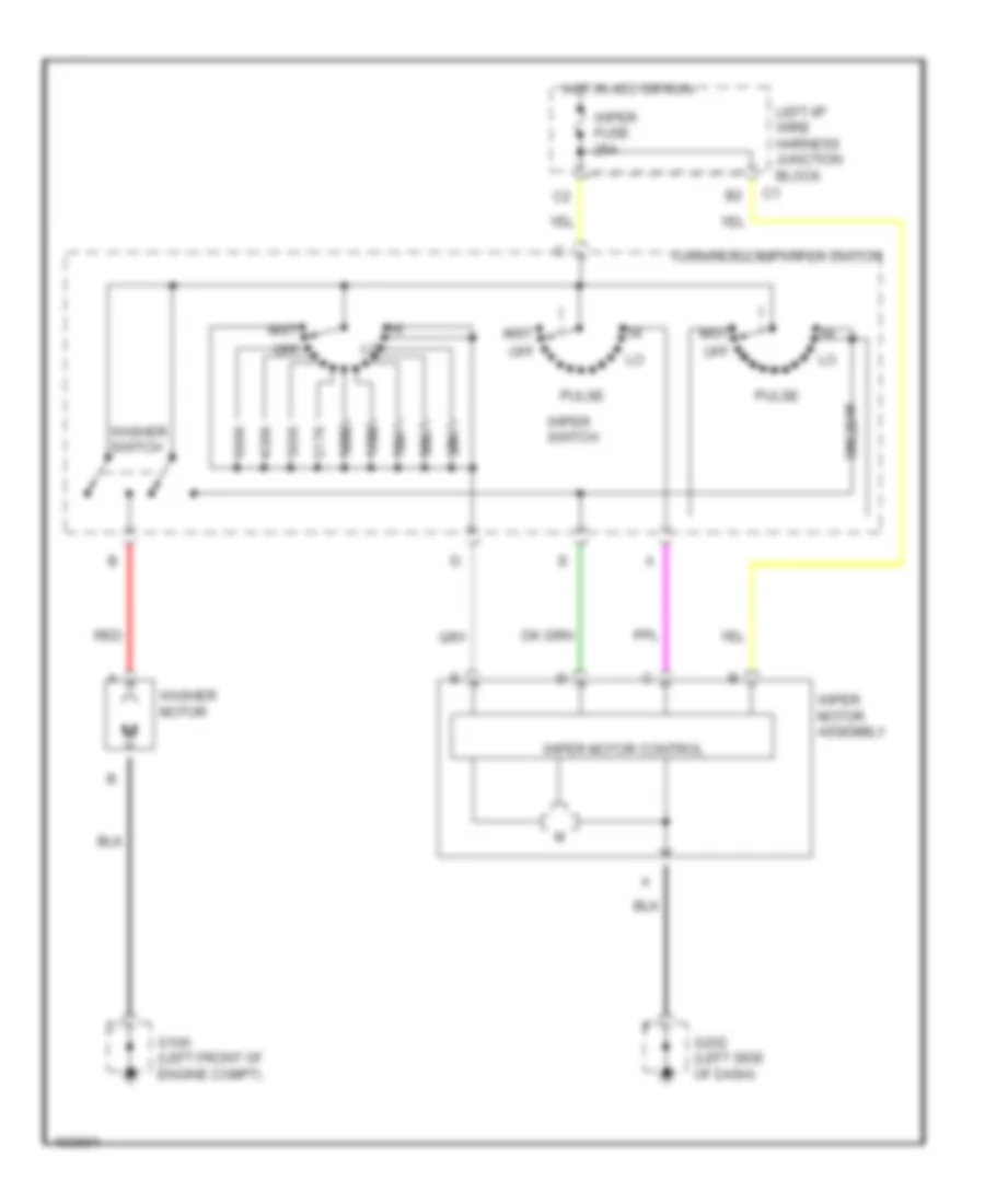
WIPER/WASHER Wiper/Washer Wiring Diagram for Oldsmobile Cutlass GL 1998 List of elements for Wiper/Washer Wiring Diagram for Oldsmobile Cutlass GL 1998: 25 110k 155k 217k 24k ohm 305k 39k 430k 55k 680k 75k G100 (left front of engine compt) G202 (left side of dash) Hot in acc or run Left i/p wire harness junction block Mist Off Pulse Red Turn/headlamp/wiper switch Washer motor Washer switch Wiper fuse 25a Wiper motor assembly Wiper motor control Wiper switch