Diagram sections — 25 (49 total)
ANTI-LOCK BRAKES ANTI-THEFT COMPUTER DATA LINES CRUISE CONTROL DEFOGGERS ENGINE PERFORMANCE EXTERIOR LIGHTS GROUND DISTRIBUTION HEADLIGHTS HORN INSTRUMENT CLUSTER INTERIOR LIGHTS POWER ANTENNA POWER DISTRIBUTION POWER DOOR LOCKS POWER MIRRORS POWER SEATS POWER WINDOWS RADIO STARTING/CHARGING SUPPLEMENTAL RESTRAINTS TRANSMISSION TRUNK, TAILGATE, FUEL DOOR WARNING SYSTEMS WIPER/WASHER
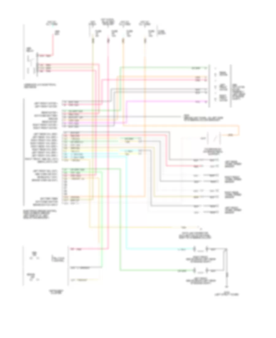
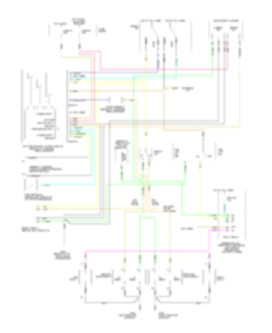
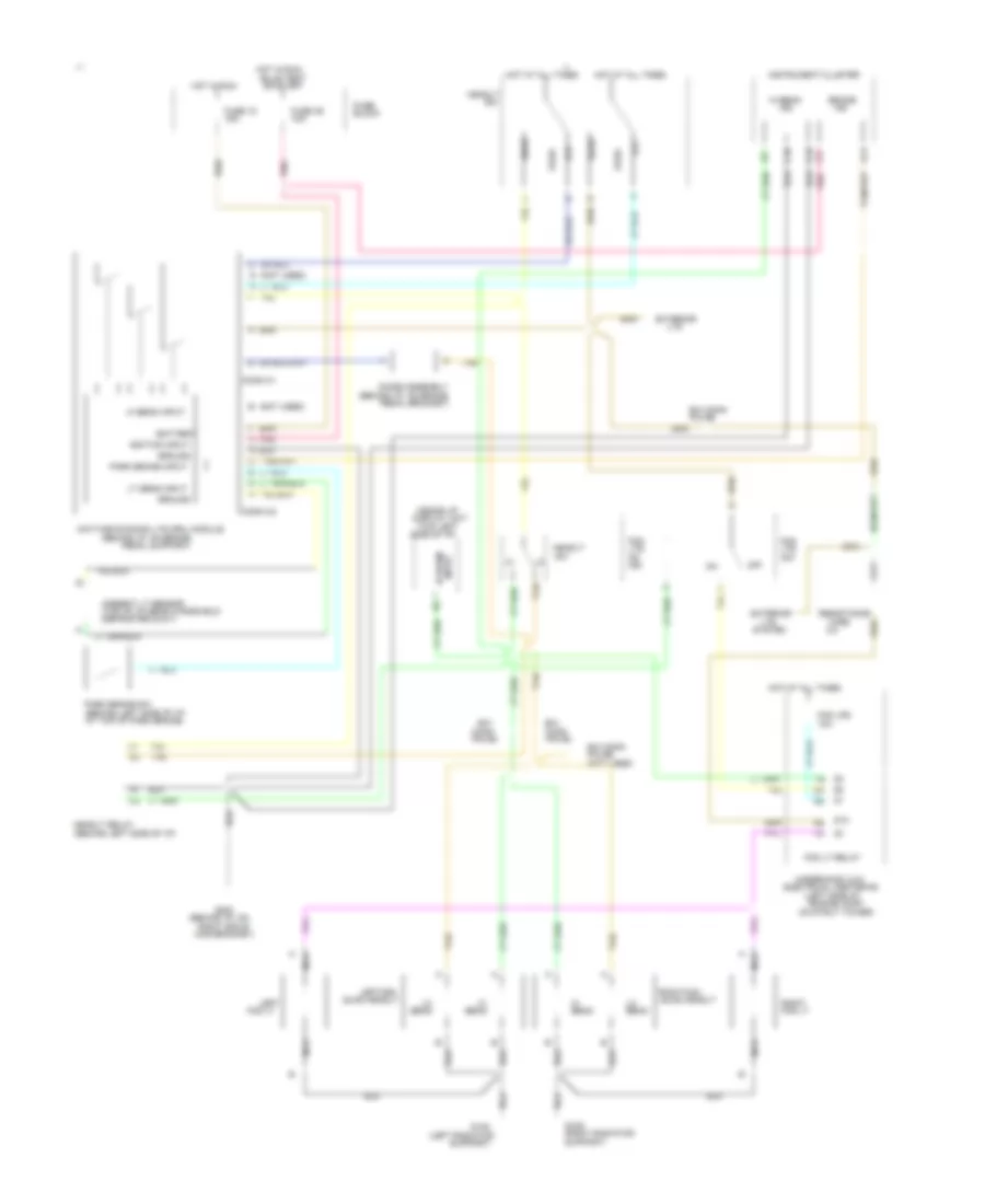
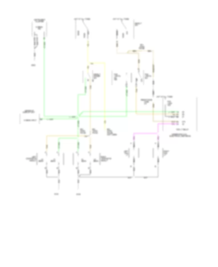
ANTI-LOCK BRAKES Anti-lock Brake Wiring Diagrams for Pontiac Grand Prix GTP 1994 List of elements for Anti-lock Brake Wiring Diagrams for Pontiac Grand Prix GTP 1994: 94 (behind inst panel, on left side (dlc) (bottom of ins panel, (left rear (left strut tower) (on brake pedal 10a 15a 60a Abs Abs solenoid (left rear Abs warn ind cntl Actuator All times Assembly B10 Battery feed Block Brake Brake switch input Brake warn ind cntl Bulb test C10 Center #2 Cluster Compt) Control D10 D11 D12 Data link connector Electronic brake control Enable rly cntl Front Fuse G102 G202 Ground Hot Hot at Hot in run, In run Ind Instrument Left Left front Left front motor + Left front motor / Left front sol cntl Left front whl spd + Left rear Left rear whl spd + Left rear whl spd / Left side of i/p, left Module (ebcm) (behind Motor Nca Of engine Of engine compt) Of steering column bracket) Or start Pnk Pnk 1281 Pnk 1632 Rear Rear motor + Rear motor / Red Red 1633 Red 885 Relay Right Right front Right front abs sol cntl Right front motor + Right front motor / Right front whl spd + Right front whl spd / Right of steering column) Right rear Right rear whl spd + Right rear whl spd / Sensor Serial data link Side of mag bracket) Support) Switched battery Switched ignition Tan Tan 800 Tan 833 Tcc/brake sw Telltale Uderhood (u/h) electrical Wheel speed
ANTI-THEFT Pass-Key Wiring Diagram for Pontiac Grand Prix GTP 1994 List of elements for Pass-Key Wiring Diagram for Pontiac Grand Prix GTP 1994: 42 "security" indicator (behind i/p, on right side of mag bracket) (behind right side of i/p) (left side of engine, on transaxle) (vin m) (vin x) 3 speed a/t 4 speed a/t Acc Bat Bulb test C23 a14 Cranking fuel enable input Fuel enable Fuse 10a Fuse 15a Fuse 5a G202 Ground Hot at all times Hot in run, bulb test or start I/p fuse block Ign Ignition key Ignition switch Instrument cluster Key res in (hi) Key res in (lo) Lock Nca Off Park/neutral position switch Pnk Powertrain control module (forward of right strut tower) Resistor pellet Run Security ind ctrl Start Starter enable ctrl Starter solenoid Theft deterrent module (behind right side of i/p, above glove box) Theft deterrent relay Transaxle range switch
COMPUTER DATA LINES Data Link Connector Wiring Diagram for Pontiac Grand Prix GTP 1994 List of elements for Data Link Connector Wiring Diagram for Pontiac Grand Prix GTP 1994: 16 (behind i/p, on right side of mag bracket) (vin x) (vin m) C10 C5 b19 Data link connector (on bottom of i/p, right of steering column) E & c data Electronic brake control module (behind i/p, left of steering column) G202 Powertrain control module (right side of engine compart- ment, forward of strut tower) Radio Sensing and diagnostic module (below front passenger seat) Serial data line Tan Tan a7 Tan b3 Trip computer (left side of i/p, left of instrument cluster)
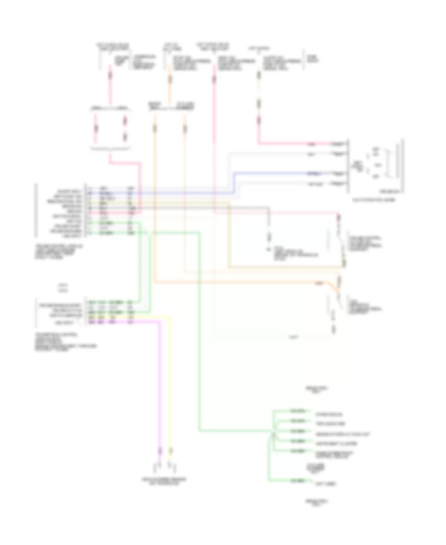
CRUISE CONTROL Cruise Control Wiring Diagram for Pontiac Grand Prix GTP 1994 List of elements for Cruise Control Wiring Diagram for Pontiac Grand Prix GTP 1994: 89 (cutlass supreme) (grand prix) (grand prix) (left front of (left side of engine (not used) (on brake pedal (on transaxle) (right side of (u/h) 15a 4000 pulses/mile A13 A19 All times B10 B13 B20 B21 B28 B29 B30 Block Brake sig Brake sw Center #1 Chime module Clstr 10a Coast Compartment near Control module Cruise Cruise control Cruise control module Cruise enable/inhibit Cruise engaged Cruise inhibit Cruise status Cruise sw Cut/off sw Cutlass Electrical Engine compartment, forward Engine, on transaxle Fuse Fuse 15 15a Fuse 23 15a Fuse 39 10a G110 Grand Grand prix Ground Heads/up display (hud) unit Hot at Hot in run Hot in run, bulb Hot in run, bulb Ignition Ignition signal Indic 10a Instrument cluster Module (pcm) Multi/function lever Nca Of strut tower) Off On/off input Only Passive restraint Pnk Powertrain control Prix R/a Resume/accel sig Set/ Set/coast sig Stop 15a Strut tower) Stud) Support) Supreme Tcc Test or start Trip computer Underhood Vehicle speed sensor Vin m Vin x Vss input
DEFOGGERS Defogger Wiring Diagram for Pontiac Grand Prix GTP 1994 List of elements for Defogger Wiring Diagram for Pontiac Grand Prix GTP 1994: 12 Fuse 15a Fuse 30a Fuse block: i/p G202 (below left side of i/p, on mag bracket) G301 (below right front seat) Hot at all times Hot in run Hvac control assembly Nca On/off defog switch Rear defogger Timer
ENGINE PERFORMANCE
3.1L 3.1L (VIN M), Engine Performance Wiring Diagrams (1 of 2) for Pontiac Grand Prix GTP 1994 List of elements for 3.1L (VIN M), Engine Performance Wiring Diagrams (1 of 2) for Pontiac Grand Prix GTP 1994: 130 (grand prix (left front of engine compartment) (left front of engine compt on air cleaner) (lower left hush panel) (right rear of engine on transaxle) (top left rear of engine block) (top left side of engine block) (top rear of engine) (top rear of engine, on intake plenum) 5 volt ref A/c clutch relay A/c clutch relay control A/c on in A/c sensor A/c sensor in A10 A11 A12 A13 A14 A15 A16 A17 A18 A19 A20 A21 A22 A23 A24 A25 A26 A27 A28 A29 A30 A31 A32 B10 B11 B12 B13 B14 B15 B16 B17 B18 B19 B20 B21 B22 B23 B24 B25 B26 B27 B28 B29 B30 B31 B32 Battery Canister purge control Chime module, trip computer, heads- up display, instrument cluster & cruise control module Conn c1 Conn c2 Convenience center Coolant temp sensor Cruise control module Cruise disable Data link connector Digital exhaust gas recirculation assembly Ecm bat fuse 20a Ect sensor in Eng emis fuse 15a Engine oil level sensor Evaporative emission canister purge valve Exhaust manifold) Fan control relay Fan relay control Fuel pump motor feed Fuel pump relay ctrl Fuse 10a G110 (lower left front of engine, on transaxle stud) Ground Heated oxygen sensor (rear of engine in Heater & a/c control assembly Hot at all times Hot in run Hot in run, bulb test or start Idle air control valve Idle air ctrl valve (top of engine on front of throttle body) Instrument cluster Intake air temp sensor Low oil ind ctrl Low oil indic Malfunction ind control Malfunction indicator Manifold absolute pressure sensor Map sensor in Nca Oil level sensor in Only) Oxygen sensor in Park/neutral out Pnk Pnp switch in Powertrain control module (right side of engine compartment, forward of strut tower) Red Second gear start request Sensor ground Serial data in/out Shift sol a out Shift sol b out Sol a Sol a control Sol b Sol b control Sol c Sol c control Tan Tcc control Tcc sol out Throttle position sensor (rear of engine, right side of throttle body) Tps sensor in Trans temp sensor in Underhood electrical center #1 Vehicle speed out Vehicle speed sensor Vehicle speed sensor in 3.1L (VIN M), Engine Performance Wiring Diagrams (2 of 2) for Pontiac Grand Prix GTP 1994 List of elements for 3.1L (VIN M), Engine Performance Wiring Diagrams (2 of 2) for Pontiac Grand Prix GTP 1994: 98 (left side of i/p) (lower left front of engine on transaxle stud) 24x crank position sensor (front left of engine, on timing chain cover) 87a A nca Anti-theft module Anti-theft system in Automatic transaxle B nca C nca C10 C11 C12 C13 C14 C15 C16 C17 C18 C19 C20 C21 C22 C23 C24 C25 C26 C27 C28 C29 C30 C31 C32 Cam position sensor in Camshaft position sensor (front top of engine) Conn c3 Crank pos sensor in Crank/cam pos sensor rtn Cruise control module Cruise on in D nca Ecm bat fuse 20a Ecm/ign fuse 15a Elec/ign fuse 15a Est bypass sig Est ctrl sig F/inj fuse 15a Fuel inj 1 out Fuel inj 2 out Fuel inj 3 out Fuel inj 4 out Fuel inj 5 out Fuel inj 6 out Fuel pump switch/oil pressure sensor sw (front center of engine near oil filter) Fuel pump priming conn Fuel pump relay (right side of engine compt fwd of strut tower) Fuel tank unit (top of fuel tank) Fuse 10a Fuse block: i/p G110 G110 (lower front of engine, on transaxle stud) G202 (behind i/p G300 (under left front seat) Ground Hot at all times Hot in run Hot in run, bulb test, or start Iat sensor in Ignition Ignition amplifier and switching module Ignition coil assembly (right rear of engine compt) Inj Knock sensor (lower right rear of engine block) Knock sensor in Low resolution 3x crankshaft position sensor Nca Of mag bracket) On right side Park/neutral position switch (left rear of engine, right top of transaxle) Plugs spark Pnk Powertrain control module (right side of engine compartment forward of strut tower) Red Ref pulse hi in Ref pulse low in Second gear start switch (behind left side of i/p) Shift sol a Shift sol b Spark plugs Tachometer Tan Tcc fuse 15a Tcc pwm sol Tcc/brake switch Trans temp switch Transaxle converter clutch Under- hood elect center #1 Underhood electrical center #1
3.4L 3.4L (VIN X), Engine Performance Wiring Diagrams (1 of 3) for Pontiac Grand Prix GTP 1994 List of elements for 3.4L (VIN X), Engine Performance Wiring Diagrams (1 of 3) for Pontiac Grand Prix GTP 1994: 120 "service (lower left front (right side of engine compartment, (steering gear assembly) (top left rear of engine) (top of engine, (top of engine, on intake plenum) * #39 (grand prix) 10a 15a 20a 5 volt ref A/c compressor relay A/c compressor rly ctrl A10 A11 A12 A13 A14 A15 A16 A17 A18 A19 A20 A21 A22 Automatic B10 B11 B12 B13 B14 B15 B16 B17 B18 B19 B20 B21 B22 Block Brake switch input Bulb test or start C16 Canister purge sol ctrl Canister purge solenoid Center #1 Chime module, instrument cluster, heads up display unit, trip computer, & cruise control module Cluster Conn c1 Conn c2 Control motor Crankshaft position sens Cruise control module Cruise ctrl "engaged" sig Cruise ctrl "inhibit" sig D16 Degr solenoid a ctrl Degr solenoid b ctrl Degr solenoid c ctrl Digital exhaust gas Ecm bat Ecm ign Electrical Eng cool fan #1 ctrl rly Eng cool fan #2 ctrl rly Eng emis Engine Evaporative emissions Fan ctrl #1 relay Fan ctrl #2 relay Feed Forward of strut tower) Fuse Fuse feed G110 Hot at all times Hot in run Hot in run, Idle air Idle air control motor Idle air ctrl motor Indic * Indicator Instrument Malfunction ind ctrl Of engine, on tran- smission stud) Of throttle assembly) Pcm ground Pnk Power steering Power steering sensor Powertrain control module Pressure switch Recirculation assembly Red Shift sol a Shift sol b Sol a Sol b Sol c Soon" Switch (behind i/p on pedal support) Tcc Tcc (pwm) sol Tcc ctrl Tcc enable sol Tcc output Tcc/brake Theft deterrent Theft deterrent module Transaxle Transaxle shift sol "a" Transaxle shift sol "b" Underhood Vehicle speed sensor (right rear of engine on transaxle stud) Vss input Vss output Vss return 3.4L (VIN X), Engine Performance Wiring Diagrams (2 of 3) for Pontiac Grand Prix GTP 1994 List of elements for 3.4L (VIN X), Engine Performance Wiring Diagrams (2 of 3) for Pontiac Grand Prix GTP 1994: 83 (lower left front (right side of engine compartment, (right side of engine, (right side of engine, below intake plenum) A/c pres sensor (left front of engine compt on a/c line) A/c pressure sensor A/c reqest on in Behind balancer at end C10 C11 C12 C13 C14 C15 C16 C17 C18 C19 C20 C21 C22 Cam shaft pos sensor Camshaft position sensor Conn c3 Conn c4 Crankshaft position sensor D10 D11 D12 D13 D14 D15 D16 D17 D18 D19 D20 D21 D22 Ect input Engine coolant temp sensor (top left side of engine) F/injn fuse 15a Forward of strut tower) Fuel inj #1 ctrl Fuel inj #2 ctrl Fuel inj #3 ctrl Fuel inj #4 ctrl Fuel inj #5 ctrl Fuel inj #6 ctrl Fuel injectors Fuel pump relay ctrl G110 Hall effect sensor Ho2s in-hi Ho2s in-lo Hot in run, bulb test or start Hvac ctrl assembly Iat sensor input Ign ctrl bypass ctrl Intake air temp sensor (left front of engine compt on air cleaner canister) Knock sensor (lower right rear of engine) Knock sensor in M data link connector (on bottom of i/p, Maf sensor in Of crankshaft) Of engine, on tran- smission stud) Pcm ground Pnk Powertrain control module Ref pulse in-hi Ref pulse in-lo Right of steering column) Serial data uart Spark control out Tan Throttle position sen in Throttle position sensor (top of engine on throttle assembly) Trans shift selector ind Transaxle range sw in Transmission range sw in Transmission temp sensor Transmission temp sensor (automatic transaxle) Underhood electrical center #1 3.4L (VIN X), Engine Performance Wiring Diagrams (3 of 3) for Pontiac Grand Prix GTP 1994 List of elements for 3.4L (VIN X), Engine Performance Wiring Diagrams (3 of 3) for Pontiac Grand Prix GTP 1994: 59 (behind i/p, on right side of mag bracket) (lower left front (lower left front of engine) (not used) (taped to harn, below underhood electrical center #2) (under left front seat) 87a A tan Amp B nca Bypass ctrl C pnk Crankshaft position sensor (right side of engine at end of crankshaft) Cutlass supreme D nca E11 Ecm bat fuse 20a Ecm ign fuse 15a Elek ign fuse 15a Eng emis fuse 15a F10 F11 Fuel pump Fuel pump relay Fuel pump/ oil pres sw (lower left front of engine below oil cooler) Fuel tank unit (below rear of vehicle top of fuel tank) Fuse 10a Fuse block G110 G110 (lower left front of engine) G202 G300 Grand price Ground Heated oxygen sensor (rear of engine, in exhaust manifold) Hot at all times Hot in run Hot in run, bulb test or start Ignition Ignition coil assembly Illum Instrument cluster Interior lights system Mass air flow (maf) sensor (top left side of engine) Nca Of engine, on tran- smission stud) Pnk Prime connector Red Second gear start switch Spark plugs Sw a Sw b Sw c System Tach Tan Transmission range switch (left rear of engine, right top of transaxle) Underhood electrical center #1
EXTERIOR LIGHTS Exterior Light Wiring Diagram, 2 Door (1 of 2) for Pontiac Grand Prix GTP 1994 List of elements for Exterior Light Wiring Diagram, 2 Door (1 of 2) for Pontiac Grand Prix GTP 1994: 57 (top left side of i/p) heads-up display unit 1995 vftc c A11 A12 A13 Air conditioning system Anti-lock brakes sysem C15 C16 Center high mounted stoplight Cruise control system Daytime running lights control module (behind left side of i/p) Fuse 23 15a Fuse 30 10a Fuse 5 15a Fuse block (right side of i/p) G108 (left radiator support) G109 (right radiator support) G202 (behind i/p, on right side of mag bracket) G301 (under right front seat) Hazard Hazard flasher (behind left side of i/p) Hazard switch Head Headlight switch Headlights system (fog lamp switch) Hot at all times Hot in run, bulb test or start Instrument cluster Left front park/ turn lamp Left front side marker lamp Left rear turn lamps Left turn ind Nca Normal Off Park lps fuse 25a Pnk Right front park/ turn lamp Right front side marker lamp Right rear turn lamps Right turn ind Solid state Tcc brake switch (on brake pedal support) c1 To rear tail/ stoplamps To tail & rear marker lamps Turn flasher (behind left side of i/p) Turn left Turn right Turn signal switch assembly Turn switch Underhood electrical center #2 (on left strut tower) W/ drl only W/ luggage rack W/o luggage rack Warning systems Warning systems (chime module) Exterior Light Wiring Diagram, 2 Door (2 of 2) for Pontiac Grand Prix GTP 1994 List of elements for Exterior Light Wiring Diagram, 2 Door (2 of 2) for Pontiac Grand Prix GTP 1994: 19 1995 vftc c 3-speed 4-speed From headlight switch From tcc/brake switch G301 (under right front seat) Hot at all times Left backup lamp Left rear side marker lamp Left tail/ stoplamp License lamps Nca Park/ neutral position switch (left side of engine, on transaxle) R/cmpt rel fuse 15a Right backup lamp Right rear side marker lamp Right tail/ stoplamp Transaxle range switch (left side of engine, on transaxle) Underhood electrical center #1 (front of right front strut tower) Exterior Light Wiring Diagram, 4 Door (1 of 2) for Pontiac Grand Prix GTP 1994 List of elements for Exterior Light Wiring Diagram, 4 Door (1 of 2) for Pontiac Grand Prix GTP 1994: 61 (top left side of i/p) heads-up display unit 1995 vftc c A11 A12 A13 Air conditioning system Anti-lock brakes sysem C15 C16 Center front park lamps Center high mounted stoplight Cruise control system Daytime running lights control module (behind left side of i/p) Fuse 23 15a Fuse 30 10a Fuse 5 15a Fuse block (right side of i/p) G108 (left radiator support) G109 (right radiator support) G202 (behind i/p, on right side of mag bracket) G301 (under right front seat) Hazard Hazard flasher (behind left side of i/p) Hazard switch Head Headlamps system (fog lamps) Headlight switch Headlights system (fog lamp switch) Hot at all times Hot in run, bulb test or start Instrument cluster Left front park/ turn lamp Left front side marker lamp Left outer front park lamp Left rear turn lamps Left turn ind Nca Normal Off Park lps fuse 25a Pnk Right front park/ turn lamp Right front side marker lamp Right outer front park lamp Right rear turn lamps Right turn ind Solid state Tcc/ brake switch (on brake pedal support) c1 To tail & rear marker lamps To tail/ stoplamps Turn flasher (behind left side of i/p) Turn left Turn right Turn signal switch assembly Turn switch Underhood electrical center #2 (on left strut tower) W/ drl only W/ luggage rack W/o luggage rack Warning systems Warning systems (chime module) Exterior Light Wiring Diagram, 4 Door (2 of 2) for Pontiac Grand Prix GTP 1994 List of elements for Exterior Light Wiring Diagram, 4 Door (2 of 2) for Pontiac Grand Prix GTP 1994: 20 1995 vftc c 3-speed 4-speed Center rear marker lamps From headlight switch From tcc/brake switch G301 (under right front seat) Hot at all times Left backup lamp Left rear side marker lamp Left tail/ stoplamp License lamps Nca Park/ neutral position switch (left side of engine, on transaxle) R/cmpt rel fuse 15a Right backup lamp Right rear side marker lamp Right tail/ stoplamp Transaxle range switch (left side of engine, on transaxle) Underhood electrical center #1 (front of right front strut tower)
GROUND DISTRIBUTION Ground Distribution Wiring Diagram (1 of 3) for Pontiac Grand Prix GTP 1994 List of elements for Ground Distribution Wiring Diagram (1 of 3) for Pontiac Grand Prix GTP 1994: 66 (3.1l) (3.4l) 2 door 3.1l 3.4l 4 door A/c comp clutch A/c comp clutch diode B16 B32 Battery Brake fluid level sw C17 Center park lt Chime module Crankshaft position sensor D10 D15 D16 D21 Data link conn Engine coolant level ind sensor Engine cooling fan #1 Engine cooling fan #2 Engine oil level sensor Fuel pump relay G102 (left strut tower) G108 (left front of engine compt, on radiator support) G108 (left radiator support) G109 (right radiator support) G110 (lower left front of engine) G110 (lower left front of engine, on transaxle stud) G202 (behind i/p, on right side of mag bracket) Head- up display Head-up display dimmer module Heated oxygen sensor High resolution crank position sensor Instrument cluster Left center park lt Left fog lt Left front abs sol Left front park lt Left front park/ turn lt Left high beam headlt Left lo beam headlt Mass air flow sensor Nca Not used Park/ neutral position sw Powertrain control module Radio Radio amplifier Right center park lt Right fog lt Right front abs sol Right front park lt Right front park/ turn lt Right high beam headlt Right lo beam headlt Second gear start sw Stepper motor cruise control module Theft deterrent module Transaxle range sw Trip computer Underhood lt Wiper motor assy Ground Distribution Wiring Diagram (2 of 3) for Pontiac Grand Prix GTP 1994 List of elements for Ground Distribution Wiring Diagram (2 of 3) for Pontiac Grand Prix GTP 1994: 51 (2 door) (4 door) (not used) (not used) b 2 door w/ sunroof 4 door w/ sunroof Air temp valve motor Auxiliary power outlet Blower motor Blower motor relay C15 C16 Daytime running lights module Dome/ reading lt Fog lt sw Fuel pump Fuel sender G202 (behind i/p, on right side of mag bracket) G300 (under left front seat) G301 (under right front seat) G908 (center of windshield header, near rear view mirror) Header courtesy/ reading lt Headlt relay Headlt sw Hvac control head I/p cigar lighter I/p compt lt sw Inside lighted mirror Instrument cluster Keyless entry receiver Left front door lock sw Left front power mirror sw Left front window sw Left power seat sw Left rear courtesy/ reading lt Nca Power antenna relay Power door lock relay Prndl indicator lt Right front door lk sw Right front window sw Right rear courtesy/ reading lt Seat belt sw Second gear start sw Sir coil assy Steering wheel control head Sunroof control unit Trip computer W/ drl W/o sunroof With console Ground Distribution Wiring Diagram (3 of 3) for Pontiac Grand Prix GTP 1994 List of elements for Ground Distribution Wiring Diagram (3 of 3) for Pontiac Grand Prix GTP 1994: 18 4 door Center high mounted stop lt G301 (under right front seat) Left backup lt Left license lt Left rear side marker lt Left rear turn lt Left tail/ stop lt Nca Nca b Rear center marker lt Rear defogger Right backup lt Right license lt Right rear side marker lt Right rear turn lt Right tail/ stop lt Trunk lid
HEADLIGHTS Headlight Wiring Diagram, 2 Door, with DRL for Pontiac Grand Prix GTP 1994 List of elements for Headlight Wiring Diagram, 2 Door, with DRL for Pontiac Grand Prix GTP 1994: 85 (behind i/p, on (behind i/p, on brake (behind left side of i/p) (behind left side of i/p, (left radiator (left side of (not used) (right radiator (top left (top of i/p near windshield 10a 15a 87a Ambient lt sensor At top of park brake) B/h B/h conn Battery Beam Block Brake Bulb test C15 C16 Conn Conn c1 Conn c2 D11 Daytime running lts (drl) module Defroster duct) Diode assembly Display unit Electrical center #2 Engine comp, Exterior Fog Fog lps Fog lt Fog lt relay Fuse Fuse 15 Fuse 39 G108 G109 G202 Ground Head Headlt Headlt relay Heads up Hi beam Hi beam input Hot at all times Hot in run Hot in run, Ignition input Ind Input Instrument cluster Left Left/mini Lt sens input Lts Mag bracket) Nca Off On strut tower) Or start Park Park brake input Park brake sw Pedal bracket) Pedal support) Pin 9b Pin 9c Pin 9d Pnk Quad headlt Right Right sie of Right/mini Side of i/p) Support) Tan Underhood (u/h) Headlight Wiring Diagram, 2 Door, without DRL for Pontiac Grand Prix GTP 1994 List of elements for Headlight Wiring Diagram, 2 Door, without DRL for Pontiac Grand Prix GTP 1994: 48 g108 g202 (behind i/p on (left radiator (left side of (not used) (right radiator (top left side of i/p) 10a 87a B/h Beam C15 C16 Cluster Conn Dimmer Display unit Electrical center #2 Engine comp, Fog Fog lt relay G109 Head Headlt Heads-up Hi beam Hi beam input Hot at all times Ind Instrument Lamp Left Lights Mag bracket) Mini-quad Nca Off On strut tower) Park Pin 9b Pin 9c Pin 9d Right Right side of Support) Tan Underhood (u/h) Headlight Wiring Diagram, 4 Door, with DRL for Pontiac Grand Prix GTP 1994 List of elements for Headlight Wiring Diagram, 4 Door, with DRL for Pontiac Grand Prix GTP 1994: 91 (behind i/p, on (behind i/p, on brake (behind left side of i/p) (behind left side of i/p, (left radiator (left side of (not used) (right radiator (top left (top of i/p near windshield 10a 15a 1994 vftc c 2.5 87a Ambient lt sensor At top of park brake) B/h B/h conn Battery Beam Block Brake Bulb test C15 C16 Conn Conn c1 Conn c2 D11 Daytime running lts (drl) module Defroster duct) Diode assembly Display unit Electrical center #2 Engine comp, Exterior Fog Fog lps Fog lt Fog lt relay Fuse Fuse 15 Fuse 39 G108 G109 G202 Ground Head Headlt Headlt relay Heads up Hi beam Hi beam input Hot at all times Hot in run Hot in run, Ignition input Ind Input Instrument cluster Left Left/mini Lt sens input Lts Mag bracket) Nca Off On strut tower) Or start Park Park brake input Park brake sw Pedal bracket) Pedal support) Pin 9b Pin 9c Pin 9d Pin 9e Pnk Quad headlt Resistance Right Right sie of Right/mini Side of i/p) Support) System Tan Underhood (u/h) Wire Headlight Wiring Diagram, 4 Door, without DRL for Pontiac Grand Prix GTP 1994 List of elements for Headlight Wiring Diagram, 4 Door, without DRL for Pontiac Grand Prix GTP 1994: 52 g108 g202 (behind i/p on (left radiator (left side of (not used) (right radiator (top left side of i/p) 10a 2.5 87a B/h Beam C15 C16 Cluster Composite Conn Dimmer Display unit Electrical center #2 Engine compt, Fog Fog lt relay G109 Head Headlt Heads/up Hi beam Hi beam input Hot at all times Ind Instrument Lamp Left Lights Mag bracket) Nca Off On strut tower) Park Pin 9b Pin 9c Pin 9d Pin 9e Resistance Right Right side of Support) Tan Underhood (u/h) Wire
HORN Horn Wiring Diagram for Pontiac Grand Prix GTP 1994 List of elements for Horn Wiring Diagram for Pontiac Grand Prix GTP 1994: 11 Cancel cam assembly Driver inflator module Horn (left side of engine compt) Horn fuse 15a Horn relay Horn switches Hot at all times Red Slip ring Steering wheel Underhood electrical center 2 (left side of engine compt)
INSTRUMENT CLUSTER Head-Up Display Wiring Diagram for Pontiac Grand Prix GTP 1994 List of elements for Head-Up Display Wiring Diagram for Pontiac Grand Prix GTP 1994: 45 fuel level input (vin m) (vin x) B28 b13 Charge indicator Coolant temp. input Coolant temp. output Display dimmer switch input Display image height motor Down E/m switch English/ metric input Exterior lights system Fuel level output Fuel pump/ oil pressure switch (front center of engine) (opens w/ normal oil pressure) Fuse 10a Fuse block G202 (left side of i/p) Generator (right rear of engine) Generator input Ground Head-up display unit (left side of i/p) Headlights system Hi beam input Hot in run, bulb test or start Hud switch assembly Indicator control Instrument cluster Interior lights system Lh turn input Max Min Off Oil pressure warning indicator Oil pressure warning input On switch input Park lamps input Pnk Pnk a Powertrain control module (right side of engine compt) Rh turn input Tan Trip computer (left side of i/p) Vehicle speed input Vehicle speed output Instrument Cluster Wiring Diagram for Pontiac Grand Prix GTP 1994 List of elements for Instrument Cluster Wiring Diagram for Pontiac Grand Prix GTP 1994: 81 (behind left side of i/p) (vin m) (vin x) (vin x) a1 b7 (vin m) 10k ohms A14 A21 c22 Abs indicator B28 b13 C12 C13 C15 C16 Charge indic- ator Chime module (behind left side of i/p) c1 Coolant level switch (right rear of radiator) (closed w/ low coolant level) Coolant temp. input D10 D12 D15 D16 Electronic brake control module (below left side of i/p) Electronic ignition control module (right front of engine) Engine coolant temp. gauge Engine coolant temperature sender (left side of engine) (high-44 ) (low-1365 ) Engine speed output Exterior lights system Fasten belts indicator Fasten belts output Fuel gauge Fuel gauge sender (top of fuel tank) (full-88 ) (empty-0 ) Fuel level input Fuel pump/ oil pressure switch (front center of engine) (opens with normal oil pressure) Fuse 10a Fuse block G110 (left front of engine) G202 G202 (left side of i/p) G300 (under left front seat) Generator (right rear of engine) Generator input Head up display unit (top left side of i/p) Head-up display unit (top left side of i/p) Headlights system Hi beam indicator Hot in run, bulb test or start Illumination (5 bulbs) Ind. cont. Indicator control Inflatable restraint indicator Instrument cluster Interior lights system Left turn indicator Low coolant indicator Low fuel indicator Low fuel input Low oil level indicator (vin m only) Low oil level sensor (center of oil pan) (closed w/ low oil level) Malfun- ction indic- ator Nca Oil level input Oil pressure warning indicator Oil pressure warning input Pnk Powertrain control module (right side of engine compt) Right turn indicator Second gear start indic- ator Second gear start request Second gear start switch (left side of i/p) Security indicator Sensing & diagnostic module (below right front seat) Speedo- meter Stepper motor drive Tachometer Tan Temp indicator Theft deterrent module (behind right side of i/p) Trip computer (left side of i/p) Vehicle speed output Vin m only Voltmeter Trip Computer Wiring Diagram for Pontiac Grand Prix GTP 1994 List of elements for Trip Computer Wiring Diagram for Pontiac Grand Prix GTP 1994: 49 (vin m) (vin x) Avg econ Avg speed B19 c5 B28 b13 Bat C14 Data in/ data out E/m Elapsed time Electronics ground English/ metric input English/ metric output Ext- temp Fuel gauge Fuel gauge sender (top of fuel tank) (full-88 ) (empty-o ) Fuel level input Fuel used Fuse 15a Fuse block G202 (left side of i/p) G300 (below left front seat) Ground Head up display unit (top left side of i/p) Hot at all times Hot in run Ign Inst econ Instrument cluster Interior lights system L/100/km/h c mi/gmph f Mode Nca Outside air temp. input Outside air temp. sensor (front of engine compt) Panel lamps (3 bulbs) Park lamps on signal Powertrain control module (right side of engine compt) Range Reset Sensor ground Serial data input Tan Trip Trip computer (left side of i/p) Vehicle speed input Vehicle speed output Vf dimming signal
INTERIOR LIGHTS Courtesy Lamps Wiring Diagram (1 of 2) for Pontiac Grand Prix GTP 1994 List of elements for Courtesy Lamps Wiring Diagram (1 of 2) for Pontiac Grand Prix GTP 1994: 47 (or red) 1995 vftc c 4-door only Chime module (below left side of i/p) Courtesy lamps ctrl Dome/reading lights Door ajar input Door lock input Door locks system (automatic door locks) Door unlock input Fuse 10a Fuse 15a Fuse block (right side of i/p) G102 (left strut tower) G202 (behind i/p, on right side of brake pedal support) G202 (behind i/p, on right side of mag bracket) G301 (under right front seat) Gnd Hd lp maxi circuit breaker 30a Headlight switch Horn fuse 15a Hot at all times Hot at all tmes Hot in run, bulb test or start I/p compartment light Ign Left front door courtesy/ warning light Left front door jamb switch Left i/p courtesy light Left rear door courtesy/ warning light Left rear door jamb switch Left vanity mirror light Nca Pnk Pnk f Right front door courtesy/ warning light Right front door jamb switch Right i/p courtesy light Right rear door courtesy/ warning light Right rear door jamb switch Right vanity mirror light Tan Trunk lid Trunk light Underhood electrical center #2 (on left strut tower) Underhood light Warning system (ignition key warning switch) Courtesy Lamps Wiring Diagram (2 of 2) for Pontiac Grand Prix GTP 1994 List of elements for Courtesy Lamps Wiring Diagram (2 of 2) for Pontiac Grand Prix GTP 1994: 16 1995 vftc c 2-door 4-door Base model Dome light Dome/ reading lights From fuse block (fuse 28) G202 (below i/p, on right side of mag bracket) Inside lighted mirror Left rear courtesy/ reading light Nca Right rear courtesy/ reading light To headlight switch Up-level model W/ sunroof W/o sunroof Instrument Illumination Wiring Diagram for Pontiac Grand Prix GTP 1994 List of elements for Instrument Illumination Wiring Diagram for Pontiac Grand Prix GTP 1994: 42 (2-bulbs) (2-door) (2-door) c1 (3-bulbs) (4-door) (5-bulbs) 1995 vftc c C15 C16 Chime module (left side of i/p, right side of mag bracket) Console prndl indicator F a Fog lamp switch G202 (behind i/p, on right side of mag bracket) G202 (behind i/p, right side of mag bracket) G301 (under right front seat) Gnd Head Head-up display Headlight switch Hot at all times Hud dimmer switch Hvac control assembly I/p dimmer switch Instrument cluster Left front door lock switch Left front window switch Lights on in Off Park Park lps fuse 25a Pwm analog dim Radio Right front door lock switch Right front window switch Second gear start switch Sir coil Steering wheel controls Trip computer Trip computer (left side of i/p) Underhood electrical center #2 (on left strut tower) Vf dim
POWER ANTENNA Power Antenna Wiring Diagram for Pontiac Grand Prix GTP 1994 List of elements for Power Antenna Wiring Diagram for Pontiac Grand Prix GTP 1994: 16 Antenna Antenna motor Antenna relay (right side of trunk) Down Down switch Fuse 19 10 amp Fuse 38 10 amp Fuse block:i/p G301 (under right front seat) Hot at all times Hot in accy or run In-line coaxial interconnect Radio Rg-62 modified coaxial cable Solid state Up switch
POWER DISTRIBUTION Power Distribution Wiring Diagram (1 of 4) for Pontiac Grand Prix GTP 1994 List of elements for Power Distribution Wiring Diagram (1 of 4) for Pontiac Grand Prix GTP 1994: 63 (3.1l) (3.4l) (not used) 15a 20a 3 speed 4 speed Abs fuse 60a Abs relay B10 B11 B14 B15 B22 Battery Blower motor relay Door lock relay Ecm bat fuse Fan control relay #1 Fan control relay #2 Fog light relay Fog lps fuse 10a Fuel pump relay Fuel pump/ oil pressure switch Fuse #1 60a Fuse #14 20a Fuse #16 30a Fuse #2 60a Fuse #23 15a Fuse #3 60a Fuse #32 20a Fuse #4 60a Fuse #5 15a Fuse block Fusible link (10 ga rust) Generator Hazard flsaher Hd lps circuit breaker 30a Headlight switch Horn fuse 15a Horn relay Hvac control assembly Ign sw1 fuse 40a Ign sw2 fuse 40a Keyless entry receiver Left power seat switch Nca Park lps fuse 25a Park/ neutral position sw Power seat circuit breaker d 30a Powertrain control module R/cmpt rel fuse Red Remote battery stud Starter assembly Tcc/ brake switch To fuse #28 (fuse block) To ignition switch Transaxle range sw Underh0od electrical center #1 Underh0od electrical center #2 Underhood electrical center #1 W/ keyless entry Power Distribution Wiring Diagram (2 of 4) for Pontiac Grand Prix GTP 1994 List of elements for Power Distribution Wiring Diagram (2 of 4) for Pontiac Grand Prix GTP 1994: 65 (2 d00r) d 2 door 3.1l 3.1l w/ 4 speed 3.4l A/c comp relay A/t Abs relay Accy Air temperature valve motor All Automatic transaxle Bulb test C (4 d00r) C10 D11 D5 nca Daytime running lights module Digital exhaust gas recirc- ulation valve Electronic brake control module Eng emis fuse 15a Evaporative emissions canister purge solenoid valve Fan control relay #2 From ign sw1 fuse (underhood electrical center #1) From ign sw2 fuse (underhood electrical center #1) Fuse #15 20a Fuse #24 15a Fuse #29 25a Fuse #33 5a Fuse #38 10a Fuse #6 20a Fuse block Generator Heated oxygen sensor Hvac control assembly Ignition switch Left front window switch Lock Multi- function lever Nca Off Others Pnk Power steering pressure switch Power window circuit breaker c 30a Radio Red Red d2 Right front window switch Run Sir coil Solenoid box Start Steering wheel control switches Sunroof control unit Tcc fuse 15a To f/injn fuse (underhood electrical center #1) To fuse #11 (fuse block) Transaxle range switch Trip computer Underhood electrical center #1 Underhood electrical center #2 W/ drl W/ steering wheel controls Wiper washer switch Power Distribution Wiring Diagram (3 of 4) for Pontiac Grand Prix GTP 1994 List of elements for Power Distribution Wiring Diagram (3 of 4) for Pontiac Grand Prix GTP 1994: 40 (3.1l) (3.4l) 3.1l 3.4l A/c compressor relay Camshaft position sensor Chime module Cruise control cut-out switch Cruise control module Cruise fuse 15a Daytime running lights module Ecm ign fuse 15a Electronic ignition control module Elek ign fuse 15a F/injn fuse 15a From ignition sw From ignition switch Fuel injectors Fuse #11 5a Fuse #12 5a Fuse #21 15a Fuse #30 10a Fuse #39 10a Fuse block Head-up display switch Headlt switch High resolution crankshaft position sensor Instrument cluster Mass air flow sensor Pnk Powertrain control module Second gear start switch Sensing and diagnostic module Tcc/ brake switch Theft deterrent module Theft deterrent relay Turn signal flasher Underhood electrical center #1 W/ drl W/ head- up display Power Distribution Wiring Diagram (4 of 4) for Pontiac Grand Prix GTP 1994 List of elements for Power Distribution Wiring Diagram (4 of 4) for Pontiac Grand Prix GTP 1994: 42 2 door w/ sunroof 2 door w/o sunroof Antenna relay Auxiliary power outlet Base Chime module Cigar lighter D1o Dome light Dome reading light Electronic electronic brake brake control control module module From fuse #4 (underhood electrical center #1) Front door courtesy lights Fuse #1 15a Fuse #10 15a Fuse #19 10a Fuse #28 15a Fuse block G202 (behind i/p, right side of mag bracket) Header courtesy reading lights I/p compt light I/p courtesy lights Inside lighted mirror Left Left front window/ door lock switch Left left rear rear courtesy courtesy reading reading lt light Nca Outside mirror control switch Radio Radio amplifier Rear door courtesy lights Red Right Right front window/ door lock switch Right rear rear courtesy courtesy reading reading lt light Theft deterrent module Trip computer Trunk courtesy light Up level Vanity mirror lights W/ sunroof W/o sunroof
POWER DOOR LOCKS Power Door Lock Wiring Diagram, with Remote/Keyless Entry for Pontiac Grand Prix GTP 1994 List of elements for Power Door Lock Wiring Diagram, with Remote/Keyless Entry for Pontiac Grand Prix GTP 1994: 53 10a 15a 20a 3 speed 4 door only 4 speed Antenna Automatic door lock signal Automatic door unlock signal Battery Chime module (behind left side of i/p, on left mag bracket) Courtesy lights control D nca Fuse 19 Fuse 32 Fuse 7 Fuse block G301 (under right front seat) Ground Headlight switch Hot at all times Interior lights system Keyless entry receiver (right side of rear shelf) Keyless programming connector (right side of trunk, above wheelhouse) Left front door lock motor Left front door lock switch Left rear door lock motor Lock Lock all doors Nca Park input Park/ neutral position switch (left of engine, on transaxle) Power door lock relay (left shroud,above center access hole) Program input R/cmpt rel fuse Remote lock input Right front door lock motor Right front door lock switch Right rear door lock motor Tan Tan e Transaxle range switch (left of engine, on transaxle) Transmitter in Trunk lid Trunk lid release Trunk lid release solenoid Trunk lid release switch Underhood electrical center #1 Unlk all doors Unlk driver's door Unlock Unlock input With automatic door locks Power Door Lock Wiring Diagram, without Remote/Keyless Entry for Pontiac Grand Prix GTP 1994 List of elements for Power Door Lock Wiring Diagram, without Remote/Keyless Entry for Pontiac Grand Prix GTP 1994: 41 (on left shroud) (vin m) (vin x) (vin m) 20a 4-door only Automatic door lock signal Automatic door unlock signal B13 b28 B18 Chime module (in component center) Door lock Fuse Fuse 20a Fuse 10a Fuse block G129 (left front of engine on transaxle stud) G301 (below right front seat) Hot at all times Interior lights Left door lock switch Left front door lock motor Left rear door lock motor Lock Lock relay Nca Park/ neutral input Park/ neutral position switch (left of engine on transaxle) Pnk Powertrain control module (engine compartment right of strut tower) Relay assembly Right front door lock motor Right rear door lock motor Right door lock switch System Tan Unlock Unlock relay Vehicle speed input Vin m (3 speed) Vin m (4 speed) Vin x
POWER MIRRORS Power Mirror Wiring Diagram for Pontiac Grand Prix GTP 1994 List of elements for Power Mirror Wiring Diagram for Pontiac Grand Prix GTP 1994: 17 * electronic circuit breaker Down Fuse 10a G300 (below left front seat) Hot at all times I/p fuse block Left Left outside mirror Left/right motor M Mirror position switch Mirror select switch Power mirror switch Right Right outside mirror Up/down motor
POWER SEATS Left Seat Wiring Diagram for Pontiac Grand Prix GTP 1994 List of elements for Left Seat Wiring Diagram for Pontiac Grand Prix GTP 1994: 19 * power seats circuit breaker d (grand prix) power acc circuit breaker (lumina) ** i/p fuse block (grand prix) component center (lumina) * 30a ** *** Back Down Entire seat For- ward Forward/ back motor Front height Front height motor G300 (under left seat) Hot at all times Left front seat Left seat switch (left side of left seat) Nca Rear height Rear height motor Tan
POWER WINDOWS Power Window Wiring Diagram, 2 Door for Pontiac Grand Prix GTP 1994 List of elements for Power Window Wiring Diagram, 2 Door for Pontiac Grand Prix GTP 1994: 11 C tan Express down module Fuse block G301 (below right front seat) Hot in run Interior lights system (rheostat controlled) Left front window motor Left front window switch Power window circuit breaker 30a Rh front window switch Right front window motor Power Window Wiring Diagram, 4 Door for Pontiac Grand Prix GTP 1994 List of elements for Power Window Wiring Diagram, 4 Door for Pontiac Grand Prix GTP 1994: 17 (below right front seat) Express down module Fuse block G301 Hot in run Interior lights system (rheostat controlled) Left front window motor Left rear window motor Left rear window switch Lh front window switch Lock- out switch Power window circuit breaker 30a Right front window motor Right front window switch Right rear window motor Right rear window switch Tan
RADIO Radio Wiring Diagrams, with Amplifier for Pontiac Grand Prix GTP 1994 List of elements for Radio Wiring Diagrams, with Amplifier for Pontiac Grand Prix GTP 1994: 74 A10 A11 A12 Amp on in Amplifier Antenna B10 B11 B12 Battery Coaxial cable Data link connector (right side of steering column) E & c data Fuse 10a Fuse 15a Fuse block Fuse out G202 (behind dash, right side of brake pedal bracket) Ground Hot at all times Hot in acc or run Ignition Illum Interior lights system Left front speaker Left rear speaker Left rear subwoofer speaker Left steering wheel radio controls Lf + Lf - Lr + Lr - Lr sub Lt frt Lt rear Nca Pnk Power antenna system Pwr antenna Radio Radio on Rf + Rf - Right front speaker Right rear speaker Right rear subwoofer speaker Right steering wheel radio controls Rr + Rr - Rr sub Rt frt Rt rear S202 S227 S239 S250 S251 S252 S253 S254 S255 S256 S260 Sir coil assembly St whl in Sw 1 Sw 2 Sw 3 Sw 4 Sw 5 Sw 6 Sw 7 Sw 8 Tan Radio Wiring Diagrams, without Amplifier for Pontiac Grand Prix GTP 1994 List of elements for Radio Wiring Diagrams, without Amplifier for Pontiac Grand Prix GTP 1994: 47 Antenna Battery Coaxial cable Data link connector (right side of steering column) E & c data Fuse 10a Fuse 15a Fuse block Fuse out G202 (behind dash, right side of steering column) Ground Hot at all times Hot in acc or run Illum Interior lights Interior lights system Left front speaker Left rear speaker Left steering wheel radio controls Lf + Lf - Lr + Lr - Nca Power antenna Pwr antenna Radio Rf + Rf - Right front speaker Right rear speaker Right steering wheel radio controls Rr + Rr - S202 S227 Sir coil assembly St whl in Sw 1 Sw 2 Sw 3 Sw 4 Sw 5 Sw 6 Sw 7 Sw 8 Tan
STARTING/CHARGING Charging Wiring Diagram for Pontiac Grand Prix GTP 1994 List of elements for Charging Wiring Diagram for Pontiac Grand Prix GTP 1994: 34 c3, c15 d2, d15 (left front of engine compt, on radiator support) (lower left front of engine) (not used) (solid state) (vin x- lower right rear of engine) *pont **buick/olds Ac sense Bat Battery Charge ind. Check gages ind. Dc sense Egn emis fuse 15a Field (rotor) Fuse block Fuse indic fuse 10a Fusible link (10 ga- rust) G108 G110 Generator (vin m- top right rear of engine) Hot in run Hot in run, bulb test or start Instrument cluster Pnk Power distribution Rectifier bridge Red Regulator Starter assembly (lower front of engine) Stator Turn on input Underhood electrical center #1 Starting Wiring Diagram for Pontiac Grand Prix GTP 1994 List of elements for Starting Wiring Diagram for Pontiac Grand Prix GTP 1994: 34 *4 speed trans **3 speed trans g, f (left front of engine compt, on radiator support) (left of engine, on transaxle) (lower left front of engine) g110 * * * * * Accy Battery Bulb test D * G108 Hold-in coil Ign sw1 maxi- fuse 40a Ign sw2 maxi- fuse 40a Ignition switch Lock Nca Off Park/neutral position switch Power distribution Pull-in coil Red Remote battery stud (at u/h electrical center #2) Run Solenoid contacts Start Starter assembly (lower front of engine) Starter enable Starter motor Theft deterrent module (behind right side of i/p, above i/p compt) Theft deterrent relay (behind right side of i/p, above i/p compt) Transaxle range switch Underhood electrical center #2
SUPPLEMENTAL RESTRAINTS Supplemental Restraint Wiring Diagram for Pontiac Grand Prix GTP 1994 List of elements for Supplemental Restraint Wiring Diagram for Pontiac Grand Prix GTP 1994: 36 A10 B10 Chime module (behind left side of i/p, on left side of mag bracket) Computer data lines Crank input Driver inflator module (center of steering wheel) Driver seat belt in Driver side "high" Driver side "low" Fuse #11 5a Fuse #21 15a Fuse #39 10a Fuse block G202 (behind (left side of i/p, on mag bracket) G300 (under left front seat) Ground Hot in run, bulb test or start Hot in start Ign 1 Indicator ign 1 Inflatable restraint ind Instrument cluster Nca Passenger inflator module (above i/p compt) Passenger side "high" Passenger side "low" Pnk Redundant ind ground Seat belt input Seat belt sw Sensing and diagnostic module (sdm) (below right front seat) Serial data line Shorting bar Sir coil assembly (inside steering wheel column) Sir indicator Tan
TRANSMISSION
3.1L 3.1L (VIN M), Transmission Wiring Diagram, 4T60-E for Pontiac Grand Prix GTP 1994 List of elements for 3.1L (VIN M), Transmission Wiring Diagram, 4T60-E for Pontiac Grand Prix GTP 1994: 92 (behind i/p, on right side (partial) 2nd gear start req 2nd gear start sw (grand prix only) 5v ref A11 A12 A13 A15 A17 A18 A19 A21 A25 A26 A27 A30 A31 A32 Automatic transaxle Automatic transaxle range sw (left of engine on transaxle) B10 B14 B15 B16 B19 B29 B30 B31 B32 Battery Brake sw in Buick oldsmobile C17 C3 c3 Control Cruise Cruise inhibit sig Cruise status Data link conn (on bottom of i/p, right of steering column) Ecm bat fuse 20a Ecm ign fuse 15a Ect sens Engine controls system Engine coolant temp (ect) sensor (top left side of engine) Fuse #39 10a Fuse #39 10a (fuse block) Fuse block: i/p G110 (lower left front of engine, on transaxle stud) G202 of steering column bracket) G205 (behind i/p on mag bracket) Ground Headlight sw Hot at all times Hot in run Hot in run, bulb test or start Ignition feed Illum Indic fuse 10a Instrument cluster (pin c6) Nca On ind On transaxle) Pnk Pnk pnk Pontiac Powertrain control module (right side of engine compt, forward of strut tower) Serial data Shift sol a Shift sol a ctrl Shift sol b Shift sol b ctrl System Tan Tcc (pwm) sol Tcc (pwm) sol ctrl Tcc enable sol Tcc fuse 15a Tcc sol ctrl Tcc/brake sw (behind i/p, on brake pedal support) Throttle position (tp) sensor (top of engine, on throttle assembly) Tp sens in Trans pos sw a Trans pos sw b Trans pos sw c Trans pos sw parity in Trans temp sens Trans temp sens in Underhood electrical center #1 Vehicle speed sensor (right rear of engine, Vss input Vss rtn
3.4L 3.4L (VIN X), Transmission Wiring Diagram, 4T60-E for Pontiac Grand Prix GTP 1994 List of elements for 3.4L (VIN X), Transmission Wiring Diagram, 4T60-E for Pontiac Grand Prix GTP 1994: 80 (behind i/p, on right side (bottom of i/p, right of steering column) (lower left front of 2nd gear input 2nd gear start sw (grand prix only) 5v ref A21 A22 Automatic transaxle B11 B20 B21 B22 Battery Brake sw in C13 C14 C17 C19 C22 Chevrolet oldsmobile Cruise control system Cruise engaged signal D10 D12 D13 D18 D19 D21 Data link connector (partial) Ecm bat fuse 20a Ecm ign fuse 15a Ect sensor Engine controls system Engine coolant temp (ect) sensor (top left side of engine) Fuse #39 10a Fuse #39 10a (fuse block) Fuse block G110 (lower left front of engine, on transaxle stud) G110 engine, on transaxle stud) G110 lower left front of engine, on transaxle stud) G202 of steering column bracket) Ground Headlight sw Hot at all times Hot in run Hot in run, bulb test or start Ignition feed Illum Indic fuse 10a On ind Pnk Pontiac Powertrain control module (right side of engine compt, forward of strut tower) Ref lo Serial data Shift sol a Shift sol a ctrl Shift sol b Shift sol b ctrl Tan Tcc (pwm) sol Tcc enable sol Tcc fuse 15a Tcc signal Tcc sol ctrl Tcc/brake sw behind i/p, on brake pedal support) Throttle position (tp) sensor (top of engine, on throttle assembly) Tp sensor Trans pos sw a Trans pos sw b Trans pos sw c Trans pos sw parity in Trans temp sens Trans temp sens in Transaxle range sw Underhood electrical center #1 Vehicle speed sensor (vss) (right rear of engine on, transaxle) Vss in Vss rtn
TRUNK, TAILGATE, FUEL DOOR Trunk Release Wiring Diagram for Pontiac Grand Prix GTP 1994 List of elements for Trunk Release Wiring Diagram for Pontiac Grand Prix GTP 1994: 13 3 speed 4 speed Hot at all times Keyless entry receiver (right side of rear shelf) Nca Nca c Park/ neutral position switch (left of engine, on transaxle) R p R/cmpt rel fuse 15a Trunk lid Trunk lid release solenoid Trunk lid release switch Underhood electrical center #1
WARNING SYSTEMS Warning System Wiring Diagrams for Pontiac Grand Prix GTP 1994 List of elements for Warning System Wiring Diagrams for Pontiac Grand Prix GTP 1994: 39 (v6 vin m) (v6 vin x) A9 tan B28 b13 Bat C12 C16 Chime module (behind left side of i/p, left side of mag bracket) Exterior lights system Fasten belts indicator Fasten belts indicator control Fuse 10a Fuse 15a Fuse block G202 (behind left of i/p, on mag bracket) G301 (below left front seat) Ground Head Hot at all times Hot in run, bulb test or start Ignition Ignition key warning switch (in steering column, at ignition key lock cylinder) Instrument cluster Key-in ignition warning Left door jamb switch (at left a pillar) Left front door open input Light switch Lights-on input Nca Off Park Pnk Powertrain control module (right side of engine compartment near strut tower) Safety belt input Safety belt switch (part of driver's seat belt assembly) Tan Turn flasher (behind i/p, right of steering column) Turn signal input Vehicle speed input Vehicle speed output
WIPER/WASHER Interval Wiper/Washer Wiring Diagram for Pontiac Grand Prix GTP 1994 List of elements for Interval Wiper/Washer Wiring Diagram for Pontiac Grand Prix GTP 1994: 20 C1 cover assembly Fuse #29 (pontiac) wiper fuse (olds, buick) 25a Fuse block G102 (left strut tower) Hot in accy or run Mechanical arm Mist Off Off k Park switch Pnk Pnk e13 Pulse Red Solid state Washer motor (in washer fluid reservoir) Washer switch Wiper motor assembly Wiper switch Wiper/ washer switch