Diagram sections — 30 (58 total)
AIR CONDITIONING ANTI-LOCK BRAKES ANTI-THEFT BODY COMPUTER COMPUTER DATA LINES COOLING FAN CRUISE CONTROL DEFOGGERS ELECTRONIC POWER STEERING ENGINE PERFORMANCE EXTERIOR LIGHTS GROUND DISTRIBUTION HEADLIGHTS HORN INSTRUMENT CLUSTER INTERIOR LIGHTS POWER DISTRIBUTION POWER DOOR LOCKS POWER MIRRORS POWER SEATS POWER TOP/SUNROOF POWER WINDOWS RADIO SHIFT INTERLOCKS STARTING/CHARGING SUPPLEMENTAL RESTRAINTS TRANSMISSION TRUNK, TAILGATE, FUEL DOOR WARNING SYSTEMS WIPER/WASHER
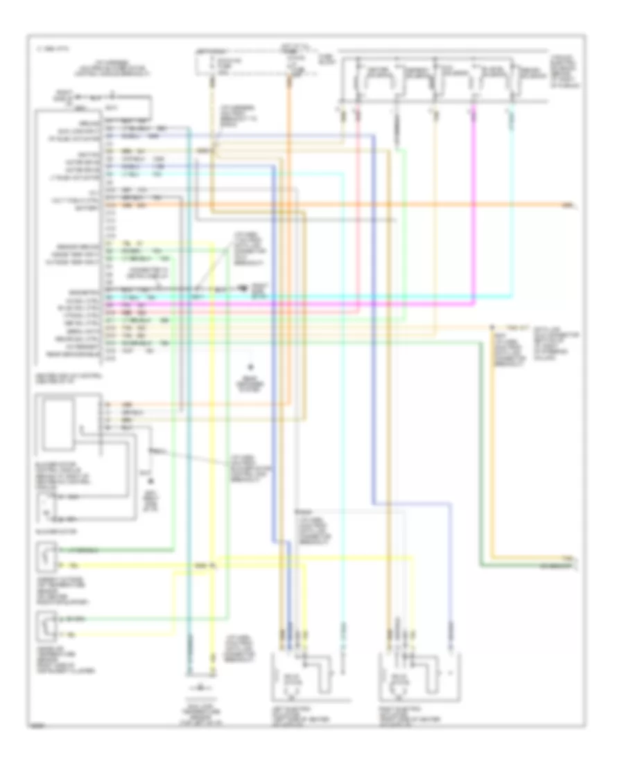
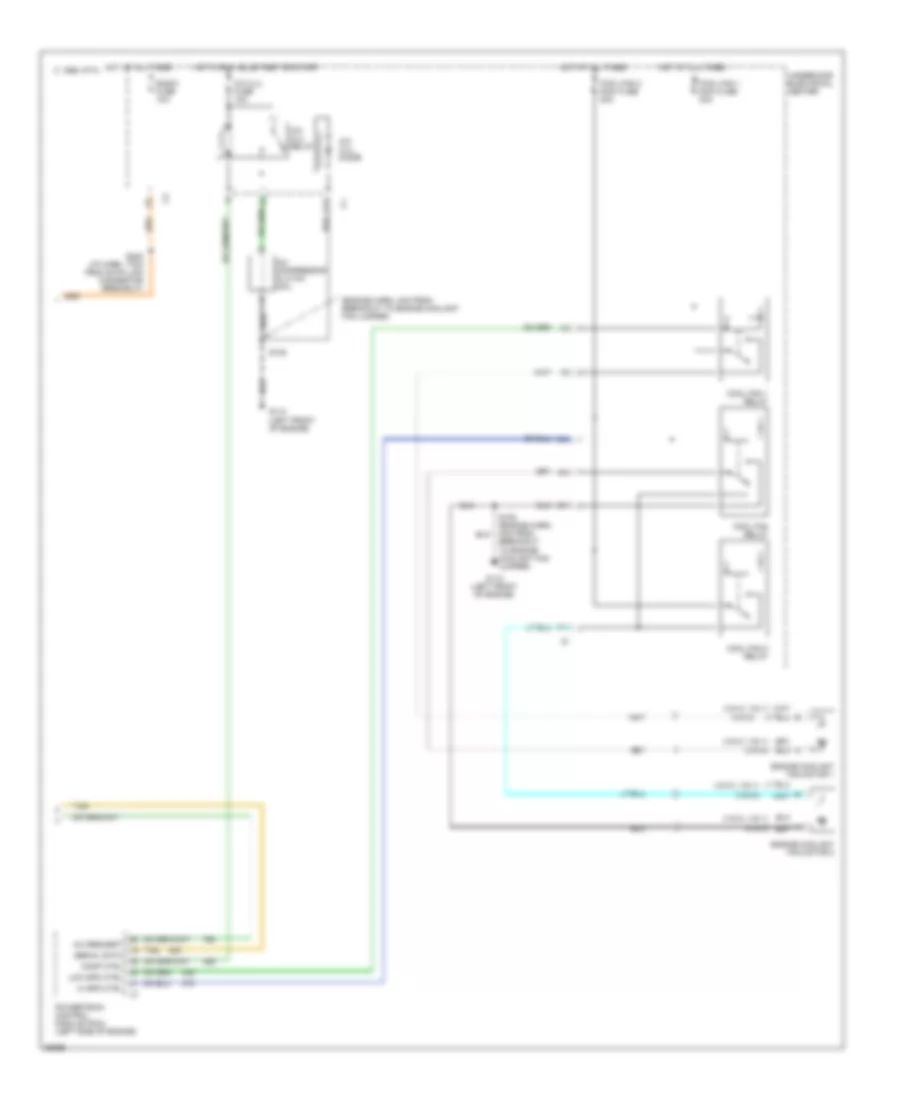
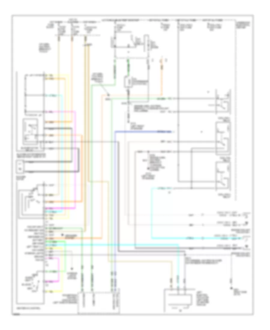
AIR CONDITIONING Air Conditioning Wiring Diagrams, Auto A/C (1 of 2) for Pontiac Grand Prix GTP 1997 List of elements for Air Conditioning Wiring Diagrams, Auto A/C (1 of 2) for Pontiac Grand Prix GTP 1997: 78 (i/p harn, 4cm from blower motor control mod breakout) (i/p harn, 11cm from data link connector (dlc) breakout) (i/p harn, 37cm from data link connector breakout) (i/p harn, 43cm from data link connector breakout) (i/p harness, 4cm from blower motor control module breakout) (i/p harness, 4cm from breakout to radio) (right side of i/p) (right side of i/p) g201 +5 v A/c request A/c sol ctrl A/c solenoid Ambient outside air temperature sensor (on center radiator support) Battery Bi-lev sol ctrl Bi-level solenoid Blower motor Blower motor control module (behind i/p, right of heater-a/c control module) C 1995 vftc C10 C11 C12 C13 C14 C15 C16 Connected w/ metric display D10 D11 D12 D13 D14 D15 D16 Data link (dlc) connector (bottom of i/p, right of steering column) Def sol ctrl Defrost solenoid Dic/hvac fuse 10a Eng/metric Fuse block G201 G201 (right side of i/p) Ground Heater and a/c control (center of i/p) Heater solenoid Hot at all times Hot in run Htr sol ctrl Hvac hi fuse 30a Ignition Inside air temperature sensor (right side of instrument cluster) Inside temp input Left electric actuator (left side of heater- a/c module) Lt elec actuator Motor drive Nca Outside temp input Rear defog enable Rear defogger system Recirc sol ctrl Recirc solenoid Red Right electric actuator (right side of heater- a/c module) Rt elec actuator S206 S211 S213 S237 (i/p harn, 30cm from data link connector breakout) S245 S258 Sensor ground Serial data Solid state Sun load input Sun load temperature sensor (top left of i/p) Tan Vacuum/ electric solenoid (behind i/p, right of plenum) Volt to blw ctrl Air Conditioning Wiring Diagrams, Auto A/C (2 of 2) for Pontiac Grand Prix GTP 1997 List of elements for Air Conditioning Wiring Diagrams, Auto A/C (2 of 2) for Pontiac Grand Prix GTP 1997: 34 (engine harn, 4cm from breakout to engine coolant fan jumper) (vin k, vin 1) (vin m) A/c clu diode A/c clu fuse 10a A/c clu relay A/c compressor clutch coil A/c request A10 C 1995 vftc C10 C11 Comp ctrl Cool fan 1 maxi fuse 30a Cool fan 1 relay Cool fan 2 maxi fuse 30a Cool fan 2 relay Cool fan relay Engine coolant fan motor 1 Engine coolant fan motor 2 F11 G110 (left front of engine) Hi spd ctrl Hot at all times Hot in run, bulb test or start Low spd ctrl Powertrain control module (pcm) (left side of engine) Radio fuse 10a S105 S105 (engine harn, 4cm from breakout to engine coolant fan jumper) S202 (i/p harn, 17cm from data link connector breakout) Serial data Tan Underhood electrical center Air Conditioning Wiring Diagrams, Manual A/C for Pontiac Grand Prix GTP 1997 List of elements for Air Conditioning Wiring Diagrams, Manual A/C for Pontiac Grand Prix GTP 1997: 68 (engine harn, 4cm from breakout to engine coolant fan jumper) (i/p harn, 17cm from breakout to dlc) (i/p harn, 4cm from breakout to dlc) (vin k, vin 1) (vin m) A/c clu diode A/c clu fuse 10a A/c clu relay A/c compressor clutch coil A/c request sig A10 Battery Bi-level Blend Blower motor Blower motor relay Blower motor resistor (behind right side of i/p) C10 C11 Clutch req Comp ctrl Cool fan 1 maxi fuse 30a Cool fan 1 relay Cool fan 2 maxi fuse 30a Cool fan 2 relay Cool fan relay Def Def mode Defogger on Defogger system Dic/hvac fuse 10a Engine coolant fan motor 1 Engine coolant fan motor 2 F11 Fan off input Fan on Fuse block G110 (left front of engine) G201 (right side of i/p) Ground Heat Heater-a/c control Hi spd ctrl Hot at all times Hot in run Hot in run, bulb test or start Hvac ctrl fuse 20a Hvac hi fuse 30a Ignition Interior lights Interior lights system Left electric actuator (left side of heater module) Left temp vlv Low spd ctrl Max Max mode Nca Off Powertrain control module (pcm) (left side of engine) Radio fuse 10a S105 S105 (engine harn, 4cm from breakout to engine coolant fan jumper) S202 S206 S213 (i/p harness, 4cm from blower motor resistor breakout) Tan Underhood electrical center Vent
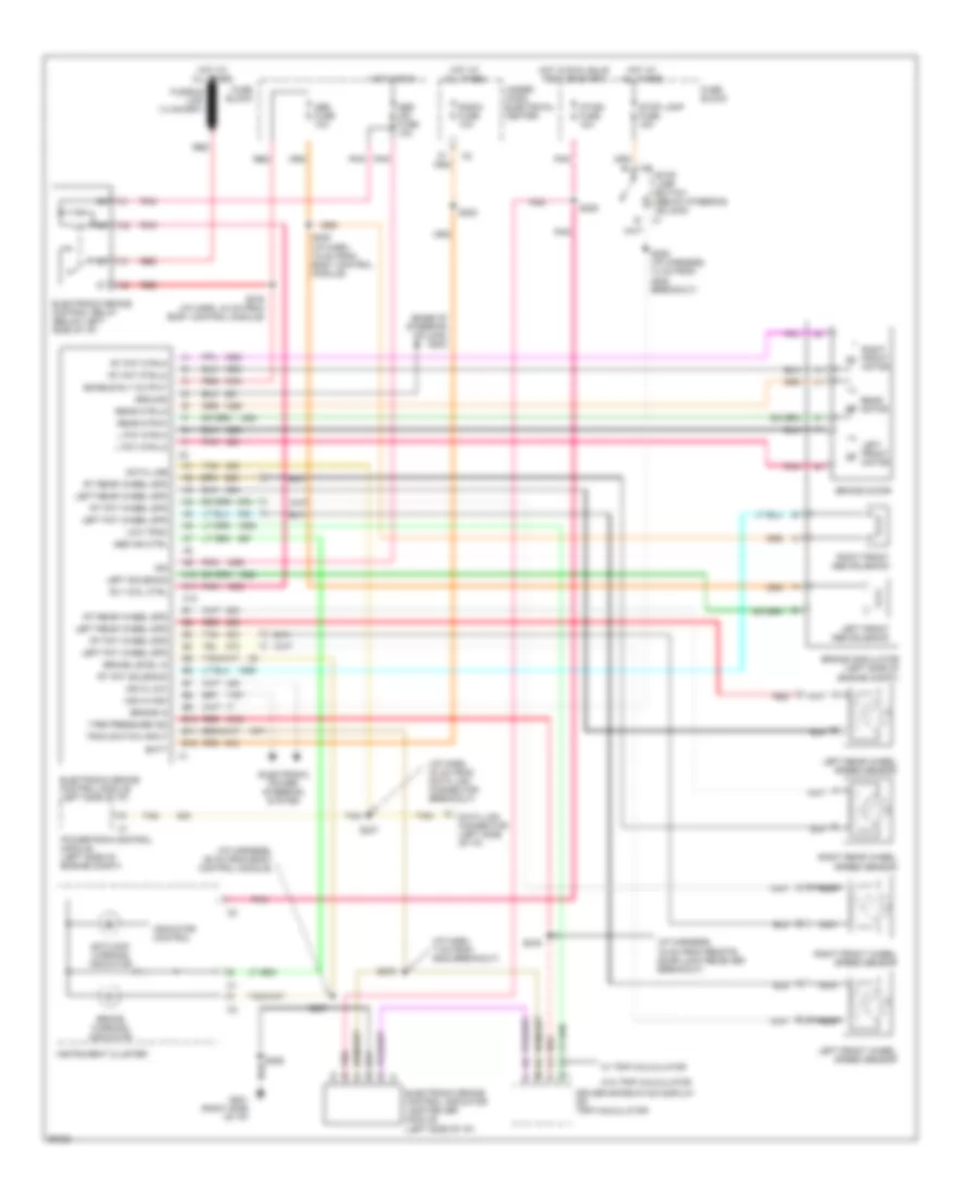
ANTI-LOCK BRAKES Anti-lock Brake Wiring Diagrams for Pontiac Grand Prix GTP 1997 List of elements for Anti-lock Brake Wiring Diagrams for Pontiac Grand Prix GTP 1997: 91 (base of steering column) g202 (i/p harn, 30 cm from data link connector breakout) (i/p harn, 7 cm from g202 breakout) (i/p harness, 16 cm from remote door lock receiver breakout) (i/p harness, 36 cm from body control module) A10 A11 A12 A3 h A4 j A6 l Abs fuse 10a Abs ign fuse 10a Abs ind ctrl Antilock warning indicator B10 B11 B12 B2 m Batt Brake in Brake level in Brake modulator (left side of engine compt) Brake motor Brake warning indicator C1 stop lamp switch (below steering column) Data line Data link connector (left side of i/p) Driver information display or trip calculator Electronic brake control indicator lamp driver module (left side of i/p) Electronic brake control module (left side of i/p) Electronic brake control relay (below left side of i/p) Electronic power steering system Enable rly output Fuse block G201 (right side of i/p) Ground Hot at all times Hot in run Hot in run, bulb test or start I/p-ign fuse 10a Ign Indicator control Instrument cluster L fnt mtr-hi L fnt mtr-lo Left fnt wheel spd Left front abs solenoid Left front motor Left front wheel speed sensor Left rear wheel spd Left rear wheel speed sensor Left solenoid Low trac Msva high Msva low Nca Pnk Powertrain control module (left side of engine compt) Radio fuse 10a Rear motor Rear mtr-hi Rear mtr-lo Red Right front abs solenoid Right front motor Right front wheel speed sensor Right rear wheel speed sensor Rly coil ctrl Rt fnt mtr-hi Rt fnt mtr-lo Rt fnt solenoid Rt fnt wheel spd Rt rear wheel spd S202 S205 (i/p harness, 14 cm from g202 breakout) S207 S209 S235 (i/p harn, 15 cm from body control module) S237 S276 S278 S279 (i/p harn, 43 cm from body control module) S285 Stop lamp fuse 15a Tan Tire pressure ind Trac switch input Under- hood electrical center W/ trip calculator W/o trip calculator
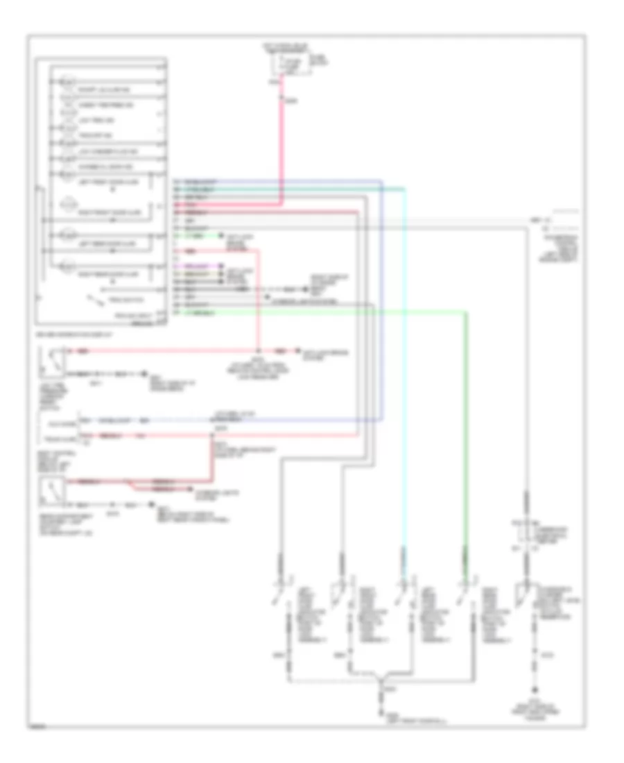
ANTI-THEFT Anti-theft Wiring Diagram for Pontiac Grand Prix GTP 1997 List of elements for Anti-theft Wiring Diagram for Pontiac Grand Prix GTP 1997: 66 (right side of i/p) g201 Accy 1 Battery Body control module (right side of i/p) C13 D10 D11 D13 D14 D15 Door locks system Driver dr ajar Ext lamps Exterior lights system Fuse block G201 (right side of i/p) G307 (below right side of rear window panel) G309 (left front door sill) Ground Headlamp circuit breaker 20a Horn system Hot at all times Hot in accy or run Hot in run, bulb test or start I/p-ign fuse 10a Ign 1 Int lamp fuse 10a Left door lock switch Left front door ajar indicator switch Left key cylinder lock switch Left rear door ajar indicator switch Lock Lock input Mall fuse 10a Mall pgm fuse 10a Pass dr ajar Pnk Program Radio fuse 20a Rear compart- ment lid ajar indicator switch Rear compartment courtesy lamp switch (on rear compartment lid) Rfa cmdi Right door lock switch Right front door ajar indicator switch Right key cylinder lock switch Right rear door ajar indicator switch S202 S209 S265 S285 S303 S309 (body harn, below right side of front passenger's seat) S416 S504 S604 Security horn sw Security indicator lamp Security led Tamper input Tan Theft deterrent relay (below left side of i/p) Theft deterrent shock sensor (below left side of i/p) Trunk ajar sw Un- lock Underhood electrical center Unlock input
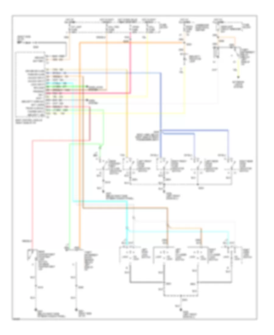
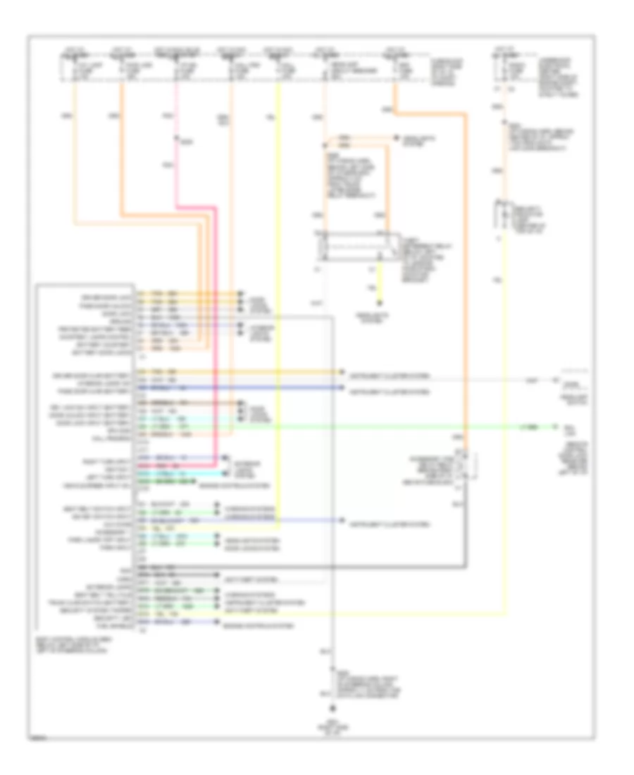
BODY COMPUTER Body Computer Wiring Diagrams for Pontiac Grand Prix GTP 1997 List of elements for Body Computer Wiring Diagrams for Pontiac Grand Prix GTP 1997: 84 Accessory 1 Accessory time delay relay (behind right side of i/p, above fuse block) Anti-theft system Aux chime Battery courtesy Battery door locks Body control module (sbm) (below left side of i/p, left of steering column) C10 C11 C12 C13 C14 C15 C16 Courtesy lamps control D10 D11 D12 D13 D14 D15 D16 Dome Door lock Door lock input (battery) Door locks system Door unlock input (battery) Driver door ajar (battery) Driver door lock Engine controls system Exterior lamps Exterior lights system Fuel enable Fuse block (right side of i/p, in i/p compt opening) G201 (right side of i/p) Ground Headlamp circuit breaker 20a Headlamp switch Headlights system Horn Hot at all times Hot in acc or run Hot in run, bulb test, or start I/p ign fuse 10a Ign key switch input Ignition 1 Instrument cluster system Int lamp fuse 10a Interior lamps "on" Interior lights system Key lock sw input (battery) Left turn input Mall fuse 10a Mall pgm fuse 10a Mall program Park input Park lamps "off" input Pass door ajar (battery) Pass door unlock Pnk Protected battery feed Pwr lock fuse 15a Radio fuse 10a Rap Rap fuse 10a Remote control door lock receiver (behind left of i/p) Rfa cmdi Rfa link Right turn input S202 (i/p wiring harn, behind center of i/p, approx 17cm from data link conn breakout) S209 S265 (i/p wiring harn, behind left side of i/p near bcm, approx 4 cm from trunk lid release relay breakout) S285 (i/p wiring harn, right of steering column, approx 11 cm from the data link connector) Seat belt switch input Seat belt telltale Security indicator lamp (center of top of i/p) Security led Security system tamper Tan Theft deterrent relay (below left of i/p, mounted to leading face of bcm mounting bracket) Trunk ajar switch (battery) Underhood electrical center (right side of engine compt, mounted to strut tower) Vehicle speed input (5v) Warning systems
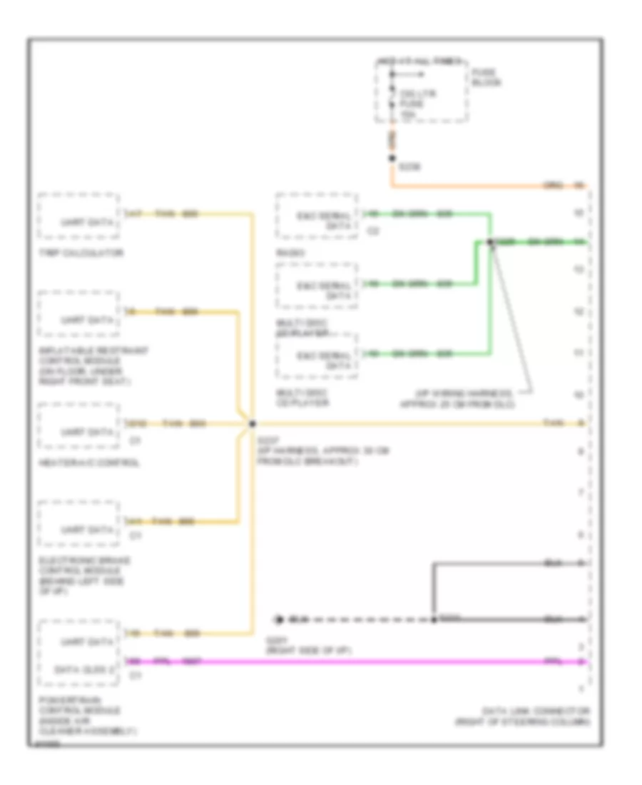
COMPUTER DATA LINES Computer Data Lines for Pontiac Grand Prix GTP 1997 List of elements for Computer Data Lines for Pontiac Grand Prix GTP 1997: 22 (i/p wiring harness, approx 25 cm from dlc) Cig ltr fuse 15a D12 Data clss 2 Data link connector (right of steering column) E&c serial data Electronic brake control module (behind left side of i/p) Fuse block G201 (right side of i/p) Heater-a/c control Hot at all times Inflatable restraint control module (on floor, under right front seat) Multi disc cd player Powertrain control module (inside air cleaner assembly) Radio S211 S225 S237 (i/p harness, approx 30 cm from dlc breakout) S238 Tan Trip calculator Uart data
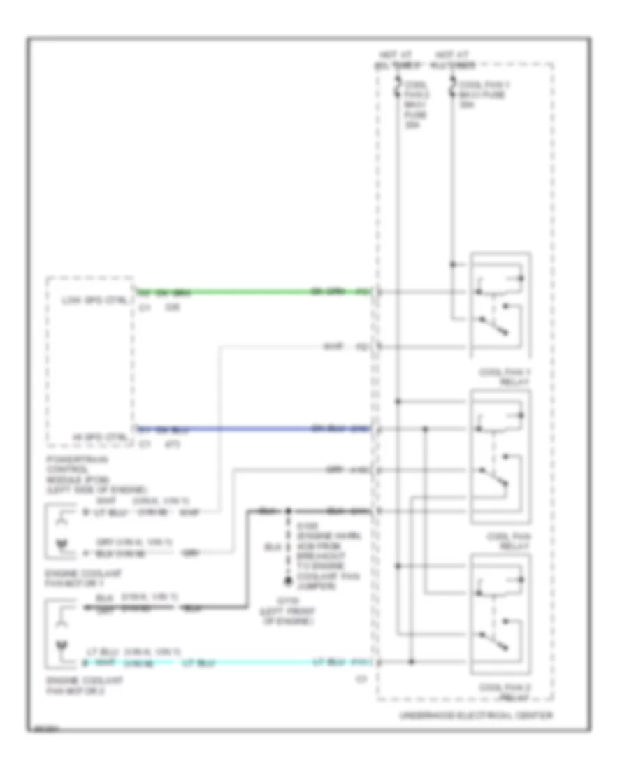
COOLING FAN Cooling Fan Wiring Diagram for Pontiac Grand Prix GTP 1997 List of elements for Cooling Fan Wiring Diagram for Pontiac Grand Prix GTP 1997: 21 (vin k, vin 1) (vin m) A10 All times C10 C11 Cool fan 2 maxi fuse 30a Cool fan 1 maxi fuse 30a Cool fan 1 relay Cool fan 2 relay Cool fan relay Engine coolant fan motor 1 Engine coolant fan motor 2 F11 G110 (left front of engine) Hi spd ctrl Hot at Low spd ctrl Powertrain control module (pcm) (left side of engine) S105 (engine harn, 4cm from breakout to engine coolant fan jumper) Underhood electrical center
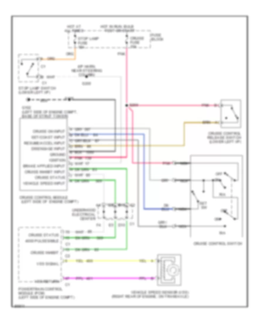
CRUISE CONTROL Cruise Control Wiring Diagram for Pontiac Grand Prix GTP 1997 List of elements for Cruise Control Wiring Diagram for Pontiac Grand Prix GTP 1997: 40 (i/p harn, near steering column) (left side of engine compt) 4000 pulses/mile All times B10 Cruise control module Cruise control release switch (lower left i/p) Cruise control switch Cruise fuse 10a Cruise inhibit Cruise inhibit input Cruise on input Cruise status D10 Disengage input Fuse block G102 (left side of engine compt, base of strut tower) Ground Hot at Hot in run, bulb Ignition Nca Off Pnk Powertrain control module (pcm) (left side of engine compt) R/a Resume/accel input S125 S205 S266 Set sw Set/coast input Stop lamp fuse 15a Stop lamp switch (lower left i/p) Test or start Underhood electrical center Vehicle speed input Vehicle speed sensor (vss) (right rear of engine, on transaxle) Vss return Vss signal
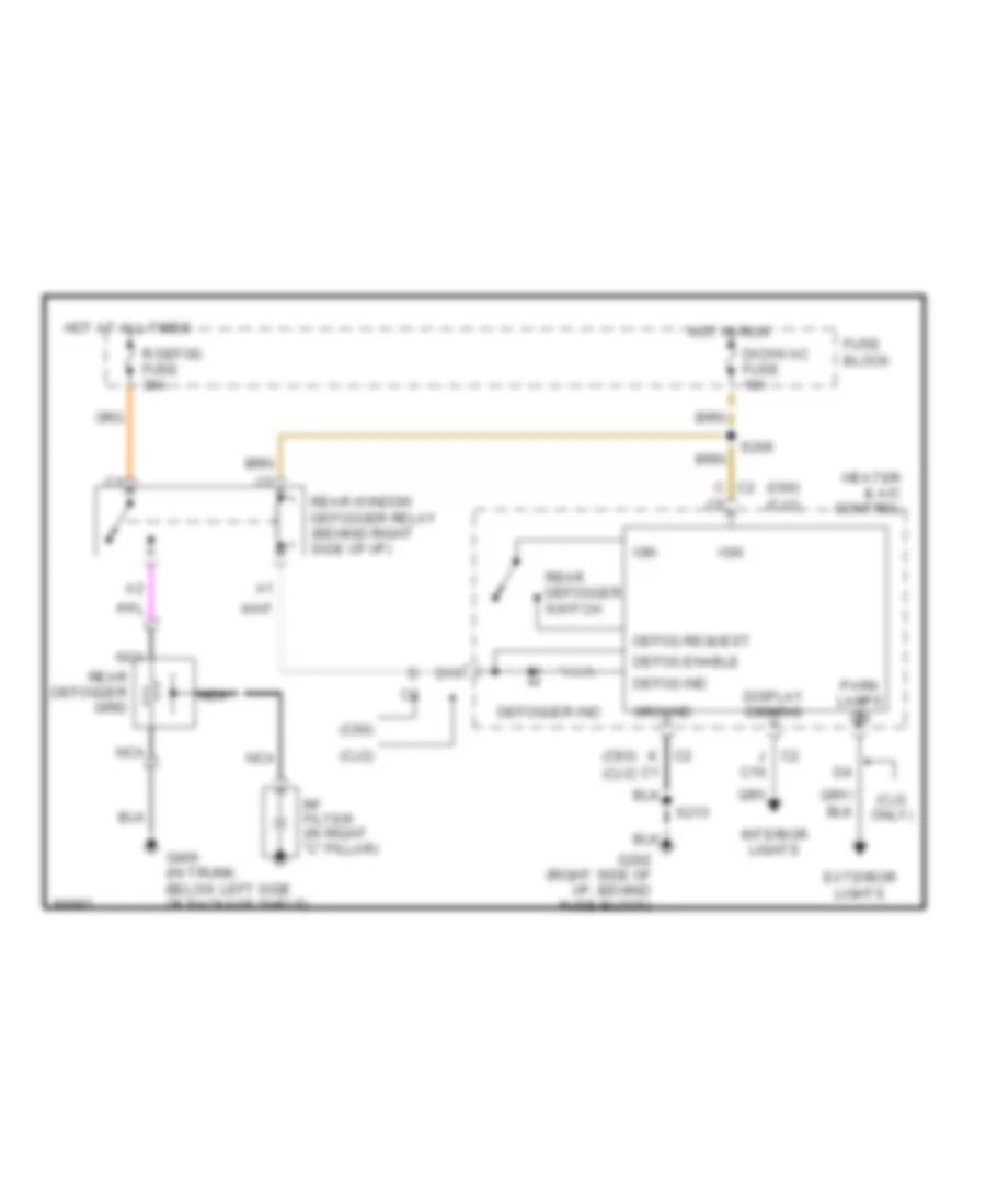
DEFOGGERS Defogger Wiring Diagram for Pontiac Grand Prix GTP 1997 List of elements for Defogger Wiring Diagram for Pontiac Grand Prix GTP 1997: 34 (c60) (c60) (cj2) (cj2 only) (cj2) C c2 C16 D15 Defog enable Defog ind Defog request Defogger ind Dic/hvac fuse 10a Display dimming Exterior lights Fuse block G202 (right side of i/p, behind fuse block) G400 (in trunk, below left side of package shelf) Ground Heater & a/c control Hot at all times Hot in run Ign Interior lights J c2 K c2 Nca Park lamps on R defog fuse 30a Rear defogger grid Rear defogger switch Rear window defogger relay (behind right side of i/p) Rf filter (in right "c" pillar) S206 S213
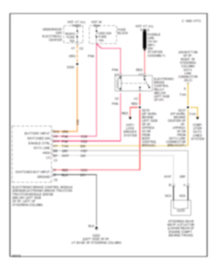
ELECTRONIC POWER STEERING Electronic Power Steering Wiring Diagram for Pontiac Grand Prix GTP 1997 List of elements for Electronic Power Steering Wiring Diagram for Pontiac Grand Prix GTP 1997: 30 (on bottom of i/p, right of steering column) data link connector (dlc) 1995 vftc c A11 Abs ign fuse 10a Anti- lock brakes system B12 Battery input Comp- uter data lines system Data line Electronic brake control module (ebcm)/electronic brake traction traction module (ebcm) (below left side of i/p, left of steering column) Electronic brake control relay (below left side of i/p) Enable ctrl Fuse block G202 (left side of i/p, at base of steering column) Ground High Hot at all times Hot in run Nca Pnk Radio fuse 10a Red S202 S237 (i/p harn, behind center of i/p, approx 30 cm from data link connector breakout) S279 (i/p harn, behind left side of i/p, approx 43 cm from body control module) Steering gear msvp actuator (lower rear of engine compt, behind trans) Switched bat input Switched ign Tan Underhood (uh) electrical center
ENGINE PERFORMANCE
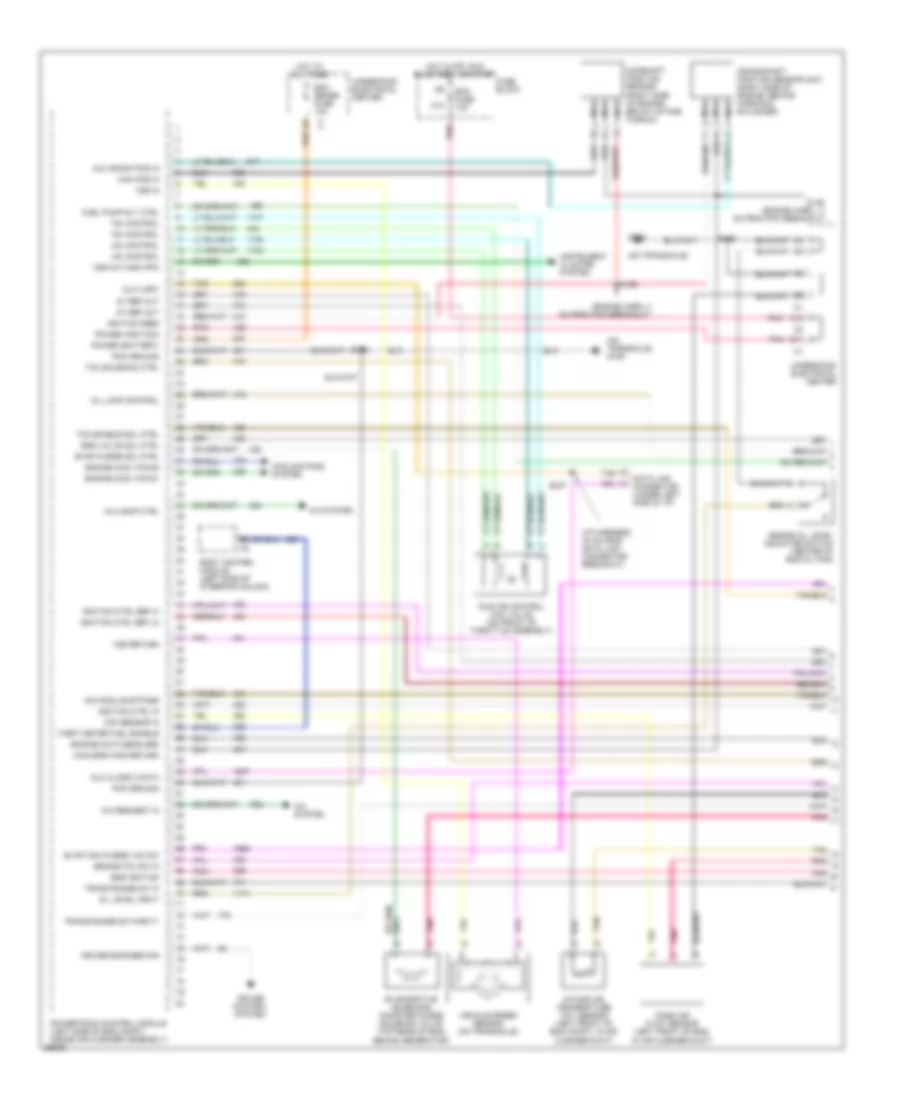
3.1L 3.1L (VIN M), Engine Performance Wiring Diagrams (1 of 3) for Pontiac Grand Prix GTP 1997 List of elements for 3.1L (VIN M), Engine Performance Wiring Diagrams (1 of 3) for Pontiac Grand Prix GTP 1997: 74 (engine harn, 11 cm from pcm breakout) (engine harn, 4 cm from pcm breakout) (i/p harness, 30 cm from data link connector breakout) (on transaxle) (on transaxle) g129 24x crank pos in 5v ref out A/c comp ctrl A/c request in A/c system Body control module (left side of steering column) Brake/tcc sw in C10 Cam pos in Cam/crnk pos return Camshaft position sensor (right side of engine, below intake plenum) Cooling fans system Crankshaft position sensor (24x) (right side of engine, behind harmonic balancer) Cruise control system Cruise engaged sig D11 Data link connector (under left side of i/p) Dlc class 2 data Dlc uart Ecm fuse 10a Ecm sense fuse 10a Egr ignition Egr valve sol ctrl Engine cool fan #1 Engine cool fan #2 Engine data sens grd Engine oil level indicator switch (center of eng oil pan) Evap can purge vac sw Evap purge sol ctrl Evaporative emissions canister purge solenoid valve (top rear of eng, behind generator) Fuel pump rly ctrl Fuse block G129 Hot at all times Hot in off, run bulb test, or start Iac control Icm module bypass Idle air control (iac) valve (on front of throttle assembly) Ignition ctrl in Ignition ctrl ref hi Ignition ctrl ref lo Ignition feed Instrument cluster system Intake air temperature (iat) sensor (left front of eng compt, in air cleaner duct) Maf sensor in Mass air flow sensor (left front of eng, in air cleaner duct) Mil lamp control Nca Oil level input Pcm ground Pnk Power (battery) Power (ignition) Powertrain control module (left side of eng compt, inside air cleaner assembly) S106 S146 S155 S237 Tan Tcc enable sol ctrl Tcc solenoid ctrl Theft deter fuel enable Trans range sw 'a' Trans range sw parity Underhood electrical center Vehicle speed sensor (on transaxle) Vss in Vss out-4000 ppm Vss return 3.1L (VIN M), Engine Performance Wiring Diagrams (2 of 3) for Pontiac Grand Prix GTP 1997 List of elements for 3.1L (VIN M), Engine Performance Wiring Diagrams (2 of 3) for Pontiac Grand Prix GTP 1997: 54 (engine harn, 10 cm from generator breakout) (engine harn, 4 cm from generator breakout) (injector harn, 2 cm from injector 3 breakout) (on transaxle) 3x ref hi 3x ref lo 7x ref hi 7x ref lo A12 Bypass ctrl Crankshaft position sensor (7x) (lower rear of engine) Elek ign fuse 15a Engine coolant temperature sensor (top left side of eng, below throttle body) Evaporative emission canister purge vacuum switch (top rear of eng, behind generator) Exhaust gas recirc- ulation valve (upper left side of eng, near throttle body) F12 Fuel pump Fuel pump fuse 15a Fuel pump relay Fuel tank Fuse 10a Fuse block G129 G129 (on transaxle) G316 (right door sill, forward of right front seat) Gnd Hot at all times Hot in run, bulb test or start I/p ign d5 Ig ctrl Ign1-uh fuse 15a Ignition control module (top center rear of eng) Instrument cluster Malfunction indicator lamp Plugs spark Pnk S105 S106 S107 S121 S122 S209 Spark plugs Stoplamp switch (on brake pedal bracket) Tan Tcc fuse 10a Throttle position sensor (on throttle assembly) Tr sw a in Tr sw b in Tr sw c in Tr sw party Transaxle range switch (top of transaxle) Underhood electrical center Underhood electrical center #1 3.1L (VIN M), Engine Performance Wiring Diagrams (3 of 3) for Pontiac Grand Prix GTP 1997 List of elements for 3.1L (VIN M), Engine Performance Wiring Diagrams (3 of 3) for Pontiac Grand Prix GTP 1997: 65 (injector harn, 2 cm from breakout to injector 2) (on transaxle) 1-2 shift solenoid 1-2 ss ctrl 2-3 shift solenoid 2-3 ss ctrl A/c press sens in A/c refrigerant pressure sensor (left side of engine compt, below accumulator) A12 Auto transaxle fluid temperature sensor B red Change oil soon ind ctrl Cruise control system Cruise inhibit out Ect sensor in Fuel inj 1 ctrl Fuel inj 2 ctrl Fuel inj 3 ctrl Fuel inj 4 ctrl Fuel inj 5 ctrl Fuel inj 6 ctrl Fuel injectors Fuse 10a G10 G129 G129 (on transaxle) Gen out signal in Generator Generator lamp ctrl Heated oxygen sensor #2 (in exhaust pipe, behind catalyst) Heated oxygen sensor #1 (rear of engine, in exhaust manifold) Ho2s 1 hi in Ho2s 1 low in Ho2s 2 hi in Ho2s 2 low in Hot coolant lamp ctrl Hot in run, bulb test and start Iat sensor in Inj g11 Instrument cluster system Knock sens in Knock sensor (front of engine, above starter) Linear egr pos sens in Low oil ind ctrl Manifold absolute pressure sensor (top rear of engine) Map sensor in Nca Pcm ground Pnk Powertrain control module (left side of eng compt, inside air cleaner assembly) Red S105 S106 S109 S115 (auto trans harn, inside tranaxle) Tach ind ctrl Tan Tcc pwm solenoid Tcc solenoid Tp sensor in Trans range sw 'b' in Trans range sw 'c' in Trans temp sens in Transaxle Underhood electrical center
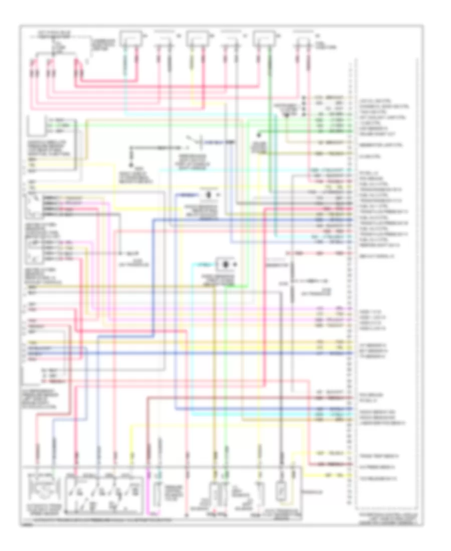
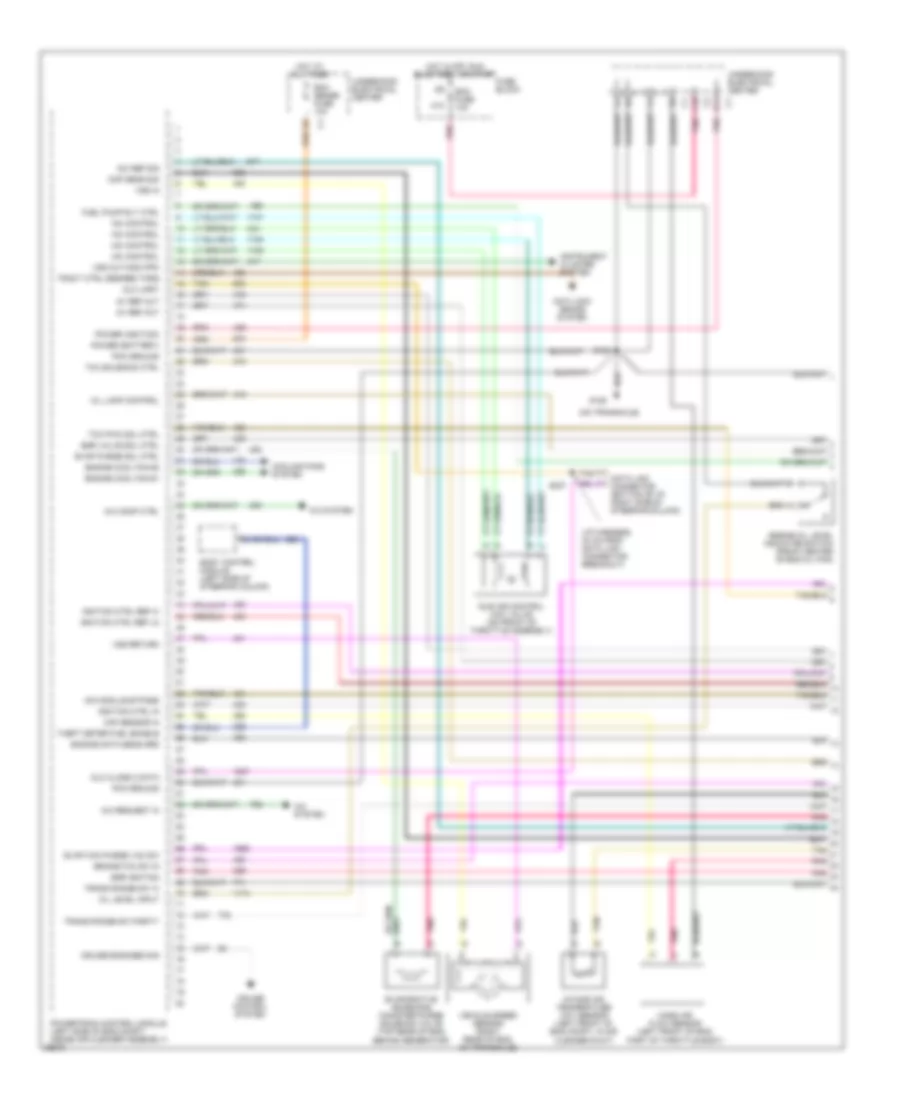
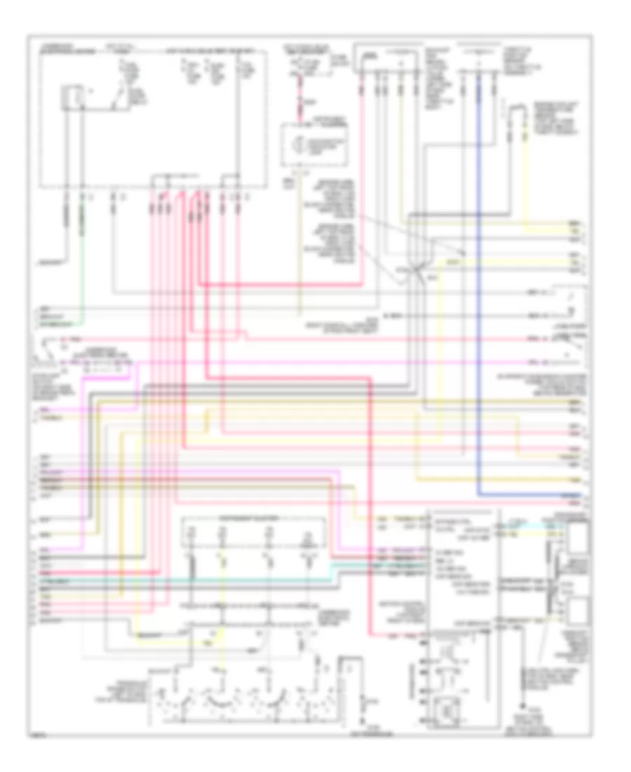
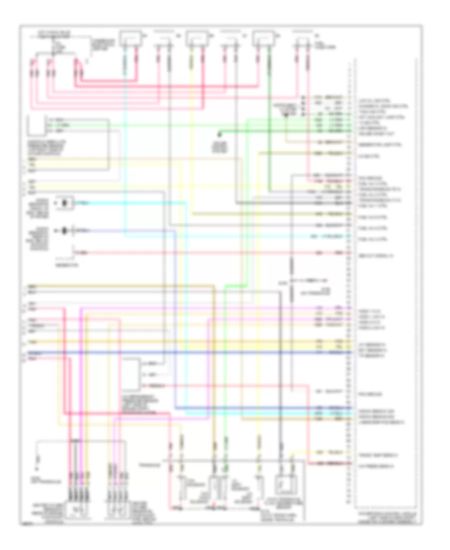
3.8L 3.8L (VIN 1), Engine Performance Wiring Diagrams (1 of 3) for Pontiac Grand Prix GTP 1997 List of elements for 3.8L (VIN 1), Engine Performance Wiring Diagrams (1 of 3) for Pontiac Grand Prix GTP 1997: 71 (i/p harness, 30 cm from data link connector breakout) (on transaxle) 18x ref sig 5v ref out A/c comp ctrl A/c request in A/c system A/t iss sens hi A/t iss sens lo Anti-lock brake system Body control module (left side of steering column) Boost ctrl sol driver Brake/tcc sw in C10 Cmp sens sig Cooling fans system Cruise control system Cruise engaged sig D11 Data link connector (bottom of i/p, right of steering column) Dlc class 2 data Dlc uart Ecm fuse 10a Ecm sense fuse 10a Egr ignition Egr valve sol ctrl Engine cool fan #1 Engine cool fan #2 Engine data sens grd Engine oil level indicator switch (front center of eng oil pan) Evap can purge vac sw Evap purge sol ctrl Evaporative emissions canister purge solenoid valve (top fron of eng, on intake manifold, behind generator) Fp spd ctrl rly ctrl Fuel pump resistor (right front frame rail, forward of front wheel) Fuel pump rly ctrl Fuse block G129 Hot at all times Hot in off, run bulb test, or start Iac control Icm module bypass Idle air control (iac) valve (on front of throttle assembly) Ignition ctrl in Ignition ctrl ref hi Ignition ctrl ref lo Instrument cluster system Intake air temperature (iat) sensor (left front of eng compt, in air cleaner duck) Maf sensor in Mass air flow sensor (left front of eng, part of throttle assembly) Mil lamp control Oil level input Pcm ground Pnk Power (battery) Power (ignition) Powertrain control module (left side of eng compt, inside air cleaner assembly) S106 S237 Super charge bypass valve (top rear of eng, near fuel injectors) Tan Tcc pwm sol ctrl Theft deter fuel enable Tract ctrl desired torq Trans range sw 'a' Trans range sw parity Underhood electrical center Vehicle speed sensor (on transaxle) Vss in Vss out-4000 ppm Vss return 3.8L (VIN 1), Engine Performance Wiring Diagrams (2 of 3) for Pontiac Grand Prix GTP 1997 List of elements for 3.8L (VIN 1), Engine Performance Wiring Diagrams (2 of 3) for Pontiac Grand Prix GTP 1997: 62 (behind harmonic balancer) (engine harn, left top front of eng, 13 cm from 10-pin black connector, near ignition module) (engine harn, left top front of eng, 4 cm from 10-pin black connector, near ignition module) (ign ctrl mod harn, top of eng, near ignition control module) (on transaxle) (right side of eng, on ignition control module bracket) 18x ref sig 3x ref sig A12 Bypass ctrl C2 a2 Camshaft position sensor (above crankshaft pulley) Ckp 18x ref Ckp sync Cmp sens gnd Cmp sens sig Crankshaft position sensor Elek ign fuse 15a Engine coolant temperature sensor (top left side of eng, below throttle body) Evaporative emission canister purge vacuum switch (top rear of eng, behind generator) Exhaust gas recirc- ulation valve (upper left side of eng, near throttle body) F/pmp spd cont relay F12 Fuel pump Fuel pump fuse 15a Fuel pump prime terminal Fuel pump relay Fuel tank Fuse 10a Fuse block G120 G129 G316 (right door sill, forward of right front seat) Gnd Hot at all times Hot in run, bulb test or start I/p ign d5 Ig ctrl Ign1- uh fuse 15a Ignition control module (top right front of eng) Instrument cluster Malfunction indicator lamp Pnk Ref lo S105 S107 S122 S144 S145 S209 Spark plugs Stoplamp switch (on right side of brake pedal bracket) Tan Tcc fuse 10a Throttle position sensor (on throttle assembly) Tr sw a in Tr sw b in Tr sw c in Tr sw party Transaxle range switch (left of eng, top of transaxle) Underhood electrical center Voltage (b+) 3.8L (VIN 1), Engine Performance Wiring Diagrams (3 of 3) for Pontiac Grand Prix GTP 1997 List of elements for 3.8L (VIN 1), Engine Performance Wiring Diagrams (3 of 3) for Pontiac Grand Prix GTP 1997: 81 (on transaxle) (right side of i/p cross beam, behind fuse box) 1-2 shift solenoid 1-2 ss ctrl 2-3 shift solenoid 2-3 ss ctrl A/c press sens in A/c refrigerant pressure sensor (left side of engine compt, on accumulator) A12 Auto transaxle fluid temperature sensor Automatic trans- axle input shaft speed sensor Automatic transaxle fluid pressure manual valve position switch B12 C12 Change oil soon ind ctrl Cruise control system Cruise inhibit out D2 sw D3 sw D4 sw Ect sensor in Fuel inj 1 ctrl Fuel inj 2 ctrl Fuel inj 3 ctrl Fuel inj 4 ctrl Fuel inj 5 ctrl Fuel inj 6 ctrl Fuel injectors G129 G129 (on transaxle) G202 Gen out signal in Generator Generator lamp ctrl Heated oxygen sensor #1 (rear of eng, in exhaust manifold) Heated oxygen sensor #2 (in exhaust pipe, behind catalyst) Ho2s 1 hi in Ho2s 1 low in Ho2s 2 hi in Ho2s 2 low in Hot coolant lamp ctrl Hot in run, bulb test and start Iat sensor in Inj fuse 10a Instrument cluster system Knock sens #1 sig Knock sens #2 sig Knock sensor #1 (rear of eng, below exhaust manifold) Knock sensor #2 (front of eng, above starter) Linear egr pos sens in Lo sw Low oil ind ctrl Manifold absolute pressure sensor (top rear of eng, near fuel injectors) Map sensor in Nca Pc sol hi Pc sol lo Pcm ground Perform shift sw in Performance shift switch (part of console shift handle) Pessure control solenoid valve Pnk Powertrain control module (left side of eng compt, inside air cleaner assembly) Red Rev sw S106 S236 Tach ind ctrl Tan Tcc pwm solenoid Tcc rel sw Tcc release sw in Tp sensor in Trans fluid press sw 'a' Trans fluid press sw 'b' Trans fluid press sw 'c' Trans range sw 'b' in Trans range sw 'c' in Trans temp sens in Transaxle Underhood electrical center 3.8L (VIN K), Engine Performance Wiring Diagrams (1 of 3) for Pontiac Grand Prix GTP 1997 List of elements for 3.8L (VIN K), Engine Performance Wiring Diagrams (1 of 3) for Pontiac Grand Prix GTP 1997: 66 (i/p harness, 30 cm from data link connector breakout) (on transaxle) 18x ref sig 5v ref out A/c comp ctrl A/c request in A/c system Anti-lock brake system Body control module (left side of steering column) Brake/tcc sw in C10 Cmp sens sig Cooling fans system Cruise control system Cruise engaged sig D11 Data link connector (bottom of i/p, right side of steering column) Dlc class 2 data Dlc uart Ecm fuse 10a Ecm sense fuse 10a Egr ignition Egr valve sol ctrl Engine cool fan #1 Engine cool fan #2 Engine data sens grd Engine oil level indicator switch (front center of eng oil pan) Evap can purge vac sw Evap purge sol ctrl Evaporative emissions canister purge solenoid valve (top rear of eng, behind generator) Fuel pump rly ctrl Fuse block G129 Hot at all times Hot in off, run bulb test, or start Iac control Icm module bypass Idle air control (iac) valve (on front of throttle assembly) Ignition ctrl in Ignition ctrl ref hi Ignition ctrl ref lo Instrument cluster system Intake air temperature (iat) sensor (left front of eng compt, in air cleaner duct) Maf sensor in Mass air flow sensor (left front of eng, part of throttle body) Mil lamp control Oil level input Pcm ground Pnk Power (battery) Power (ignition) Powertrain control module (left side of eng compt, inside air cleaner assembly) S106 S237 Tan Tcc pwm sol ctrl Tcc solenoid ctrl Theft deter fuel enable Tract ctrl desired torq Trans range sw 'a' Trans range sw parity Underhood electrical center Vehicle speed sensor (right rear of eng, on transaxle) Vss in Vss out-4000 ppm Vss return 3.8L (VIN K), Engine Performance Wiring Diagrams (2 of 3) for Pontiac Grand Prix GTP 1997 List of elements for 3.8L (VIN K), Engine Performance Wiring Diagrams (2 of 3) for Pontiac Grand Prix GTP 1997: 59 (behind harmonic balancer) (engine harn, left top front of eng, 13 cm from 10-pin black connector, near ignition module) (engine harn, left top front of eng, 4 cm from 10-pin black connector, near ignition module) (ign ctrl mod harn, top of eng, near ignition control module) (on transaxle) 18x ref sig 3x ref sig A12 Bypass ctrl Camshaft position sensor (above crankshaft pulley) Ckp 18x ref Ckp sync Cmp sens gnd Cmp sens sig Crankshaft position sensor Elek ign fuse 15a Engine coolant temperature sensor (top left side of eng, below throttle body) Evaporative emission canister purge vacuum switch (top rear of eng, behind generator) Exhaust gas recirc- ulation valve (upper left side of eng, near throttle body) F12 Fuel pump Fuel pump fuse 15a Fuel pump relay Fuel tank Fuse 10a Fuse block G120 G129 G316 (right door sill, forward of righ front seat) Gnd Hot at all times Hot in run, bulb test or start I/p ign d5 Ig ctrl Ign1- uh fuse 15a Ignition control module (top right front of eng) Instrument cluster Malfunction indicator lamp Pnk Ref lo Right side of eng, on ignition control module bracket) S105 S107 S122 S144 S145 S209 Spark plugs Stoplamp switch (on right side of brake pedal bracket) Tan Tcc fuse 10a Throttle position sensor (on throttle assembly) Tr sw a in Tr sw b in Tr sw c in Tr sw party Transaxle range switch (left of eng, top of transaxle) Underhood electrical center Voltage (b+) 3.8L (VIN K), Engine Performance Wiring Diagrams (3 of 3) for Pontiac Grand Prix GTP 1997 List of elements for 3.8L (VIN K), Engine Performance Wiring Diagrams (3 of 3) for Pontiac Grand Prix GTP 1997: 65 (on transaxle) 1-2 shift solenoid 1-2 ss ctrl 2-3 shift solenoid 2-3 ss ctrl A/c press sens in A/c refrigerant pressure sensor (left side of engine compt, on accumulator) A12 Auto transaxle fluid temperature sensor B red B12 C12 Change oil soon ind ctrl Cruise control system Cruise inhibit out Ect sensor in Fuel inj 1 ctrl Fuel inj 2 ctrl Fuel inj 3 ctrl Fuel inj 4 ctrl Fuel inj 5 ctrl Fuel inj 6 ctrl Fuel injectors G129 G129 (on transaxle) Gen out signal in Generator Generator lamp ctrl Heated oxygen sensor #2 (in exhaust pipe, behind catalyst) Heated oxygen sensor #1 (rear of engine, in exhaust manifold) Ho2s 1 hi in Ho2s 1 low in Ho2s 2 hi in Ho2s 2 low in Hot coolant lamp ctrl Hot in run, bulb test and start Iat sensor in Inj fuse 10a Instrument cluster system Knock sens #1 sig Knock sens #2 sig Knock sensor #1 (rear of eng, below exhaust manifold) Knock sensor #2 (front of eng, above starter) Linear egr pos sens in Low oil ind ctrl Manifold absolute pressure sensor (top right side of intake manifold) Map sensor in Nca Pcm ground Pnk Powertrain control module (left side of eng compt, inside air cleaner assembly) Red S105 S106 S115 (auto trans harn, inside tranaxle) Tach ind ctrl Tan Tcc pwm solenoid Tcc solenoid Tp sensor in Trans range sw 'b' in Trans range sw 'c' in Trans temp sens in Transaxle Underhood electrical center
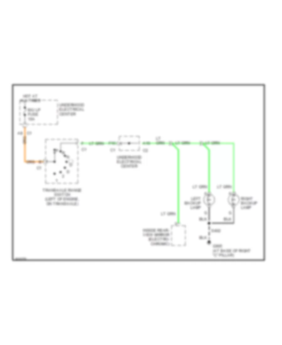
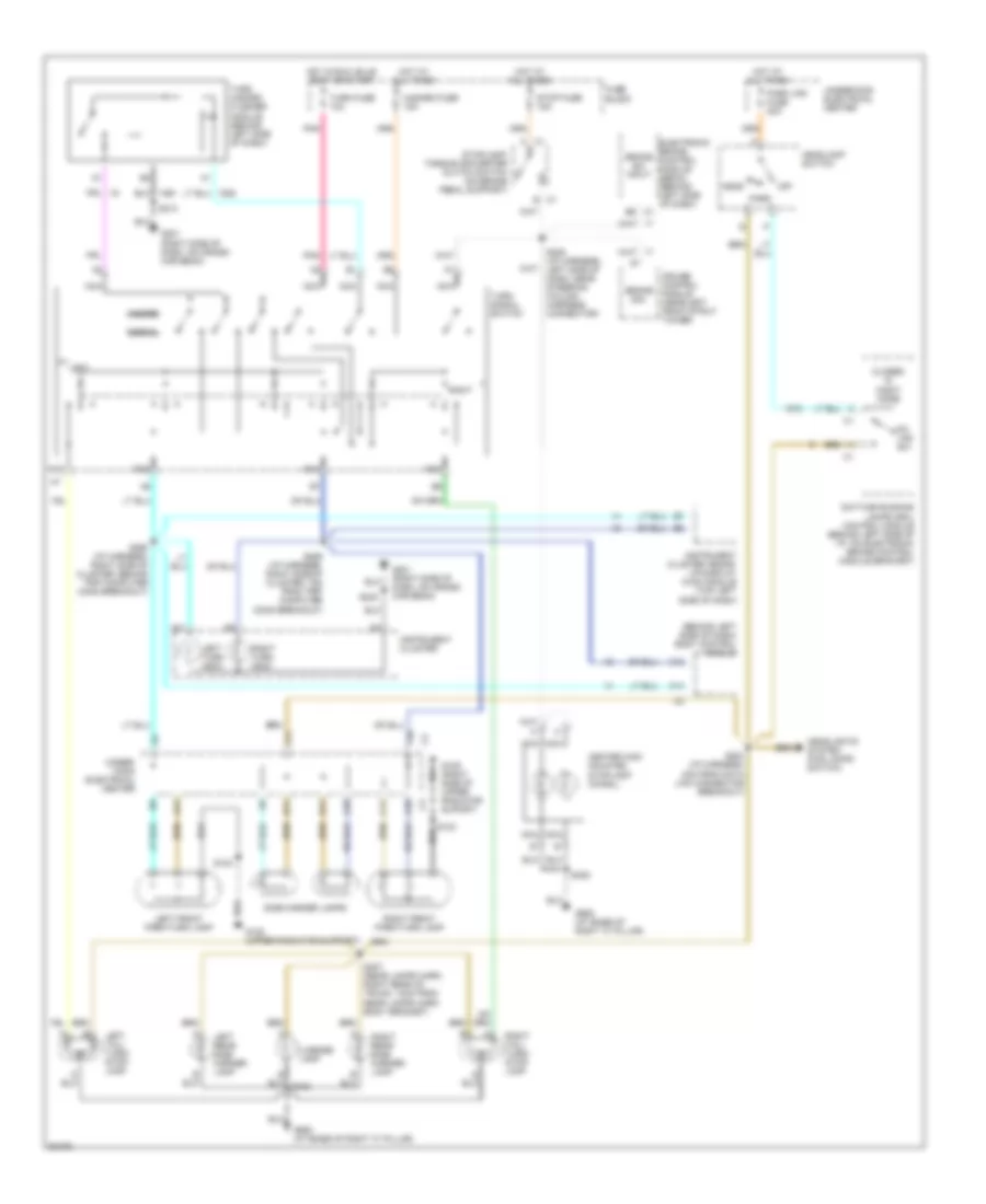
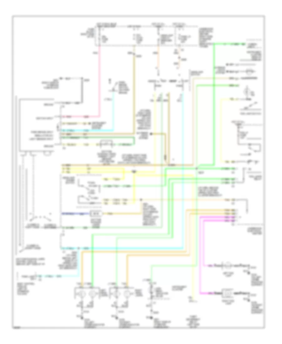
EXTERIOR LIGHTS Back-up Lamps Wiring Diagram for Pontiac Grand Prix GTP 1997 List of elements for Back-up Lamps Wiring Diagram for Pontiac Grand Prix GTP 1997: 12 A10 A8 c1 B/u lp fuse 10a F10 G905 (at base of right "c" pillar) Hot at all times Inside rear- view mirror (electro- chromic) Left backup lamp Right backup lamp S402 Transaxle range switch (left of engine, on transaxle) Underhood electrical center Exterior Lamps Wiring Diagram for Pontiac Grand Prix GTP 1997 List of elements for Exterior Lamps Wiring Diagram for Pontiac Grand Prix GTP 1997: 70 (behind left side of dash) body control module A c1 A10 A11 B c1 B11 B9 c1 Brake sig. Brake sw input C11 C12 C14 Center high mounted stoplamp (chmsl) Closed in night mode Cruise control module (near left front strut tower) D11 Daytime running lamps (drl) control module (behind left side of i/p, on electronic brake control module bracket) Electronic brake control module (ebcm) (behind left side of dash) F10 F11 Fuse block G108 (upper radiator support) G109 (right side of upper radiator suport) G201 (right side of dash, on cross- car beam) G905 (at base of right "c" pillar) Hazard Hazard fuse 15a Head Headlamp switch Headlights system (fog lamps switch) Hot at all times Hot in run, bulb test or start Instrument cluster Instrument cluster heads- up-display (hud) module (top left side of dash) Left Left front park/turn lamp Left rear side marker lamp Left tail/ turn/ stop- lamp Left turn indic License lamp Nca Normal Off Park Park lps fuse 20a Pk lps sw Pnk Right Right front park/turn lamp Right rear side marker lamp Right tail/ turn/ stop- lamp Right turn indic S123 S124 S204 (i/p harness, 4cm from data link connector breakout) S205 (i/p harness, left side of dash, near steering column harness connector) S213 S230 S289 (i/p harness, right side of cluster, 7cm from trip computer conn breakout) S290 (i/p harness, right side of cluster, behind trip computer conn breakout) S406 S407 (rear lamps harn, right rear of trunk, 12cm from rear lamps harn body grommet) Side marker lamps Stop fuse 15a Stoplamp/ torque converter clutch switch (on brake pedal support) Turn fuse 10a Turn hazard flasher module (behind left side of dash) Turn signal switch Under- hood electrical center Underhood electrical center
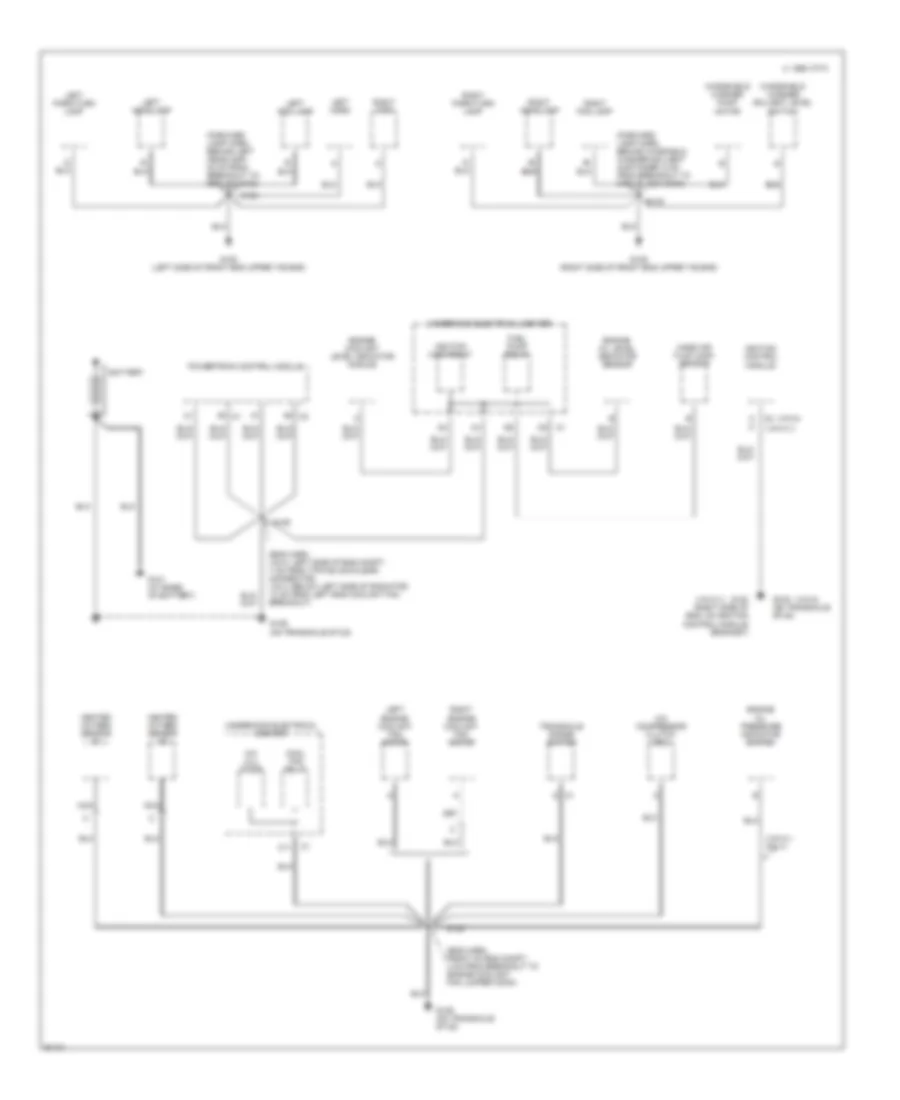
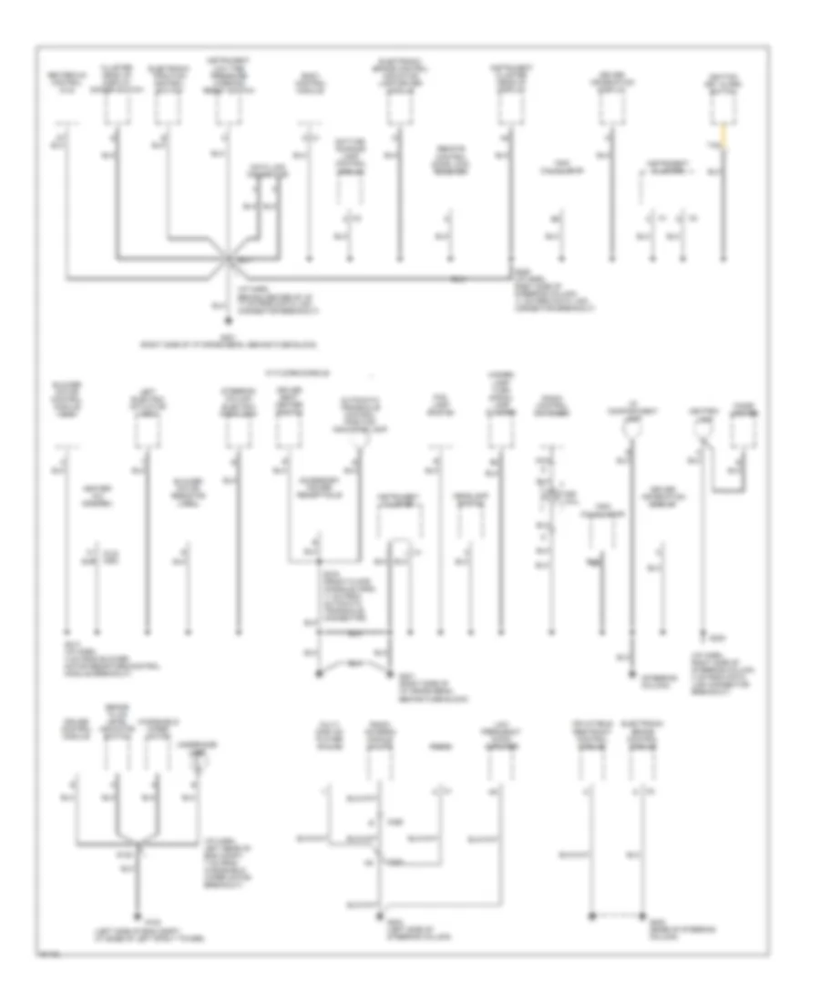
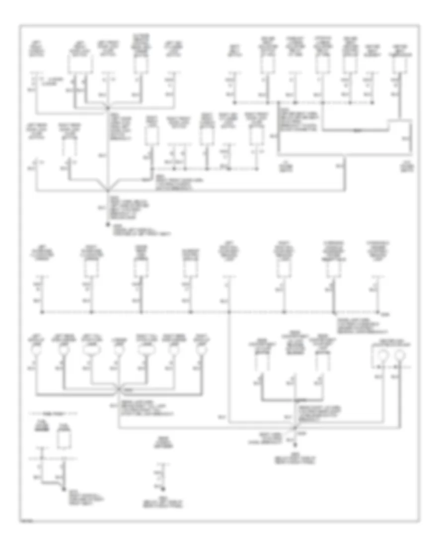
GROUND DISTRIBUTION Ground Distribution Wiring Diagram (1 of 3) for Pontiac Grand Prix GTP 1997 List of elements for Ground Distribution Wiring Diagram (1 of 3) for Pontiac Grand Prix GTP 1997: 50 (eng harn, front of eng compt, 4 cm from breakout to engine coolant fan jumper conn) (eng harn, vin m: left side of eng compt, 7 cm from 7-pin black/clear connector; vin x: below left side of radiator, 13 cm from left eng coolant fan breakout) (forward lamp harn, behind left headlamp, 30 cm from breakout to ground g108) (forward lamp harn, behind winshield washer solvent container, 5 cm from breakout to 3-pin black conn) (vin k,1 only) (vin k,1) (vin m) 1995 vftc c A a A/c clu diode A/c compressor clutch coil B b Battery C1 d C11 Cool fan relay Engine coolant level indicator module Engine oil level indicator sensor Engine oil pressure indicator switch Fuel pump relay G101 (at base of battery) G108 (left side of front end upper tie bar) G109 (right side of front end upper tie bar) G120 (right side of eng, on ignition control module bracket) G129 (on transaxle stud) Heated oxygen sensor #1 Heated oxygen sensor #2 Ignition control module Ignition main relay Left engine coolant fan motor Left fog lamp Left headlamp Left horn Left park/turn lamp Mass air flow (maf) sensor Nca Powertrain control module Right engine coolant fan motor Right fog lamp Right headlamp Right horn Right park/turn lamp S105 S106 S123 S124 Transaxle range switch Underhood electrical center Windshield washer pump motor Windshield washer solvent level switch Ground Distribution Wiring Diagram (2 of 3) for Pontiac Grand Prix GTP 1997 List of elements for Ground Distribution Wiring Diagram (2 of 3) for Pontiac Grand Prix GTP 1997: 64 (i/p harn, behind center of i/p, 11 cm from data link connector breakout) (i/p harn, left rear of eng compt, 7 cm from windshield wiper motor breakout) (i/p harn, right side of steering column, 4 cm from data link connector breakout) (left side of eng compt, at base of left strut tower) (steering column) Accessory power receptacle Ashtray lamp Automatic transaxle control position indicator lamp Blower motor control module (cj2) Blower motor resistor (c60) Body control module Brake fluid level indicator switch C1 d C1 l C2 a C2 d C200 C395 Cigar lighter Cluster head up display dimmer switch Cruise control module Data link connector Daytime running lamp control module Driver information display Driver seat heater switch Electronic brake control indicator lamp driver module Electronic brake control module Electronic traction control switch Fog lamp switch G102 G201 (right side of i/p cross beam, behind fuse block) G202 (base of steering column) G204 (left side of steering column) Hazard lamp/ turn signal lamp flasher Headlamp switch Heater- a/c control Heater-a/c control (cj2) I/p compartment lamp Ignition key alarm switch Inflatable restraint control module Instrument Instrument cluster Instrument cluster head-up display Left electric actuator (c60) Low frequency audio amplifier Low tire pressure warning reset switch Multi disc cd player (w/ u18) Nca Radio Radio antenna module (w/ u77) Radio control switches Remote control door lock receiver S125 S211 S213 (i/p harn, 4 cm from blower motor resistors/control module breakout) S230 S285 (i/p harn, right side of steering column, 11 cm from data link connector breakout) Sir coil Steering column electric park lock Tan Trip calculator Underhood lamp W/ floor console Windshield wiper motor Ground Distribution Wiring Diagram (3 of 3) for Pontiac Grand Prix GTP 1997 List of elements for Ground Distribution Wiring Diagram (3 of 3) for Pontiac Grand Prix GTP 1997: 63 (2 door) (4 door) (body harn, 15 cm from chmsl breakout) (dome lamp harn, 4 cm from windshield header courtesy/ reading lamps breakout) (rear compt lid harn, 8 cm from rear compt lid release switch breakout) (rear lamp harn, behind right tail lamp, 4 cm from right tail/ stop/turn lamp breakout) Center high mounted stoplamp Driver seat adjuster switch (w/ ag1) Driver seat heater control module Fore/aft lumbar adjuster relay (w/ ag6) Fuel gauge sender Fuel pump Fuel tank G309 (inside left door sill, forward of left front seat) G316 (right door sill, forward of right front seat) G904 (below left side of rear window panel) G905 (below right side of rear window panel) Heated seat element Heated seat thermistor Inside rear view mirror Left back-up lamp Left front door lock (ajar switch) Left front door lock switch Left front window switch Left key cylinder lock switch Left rear door lock (ajar switch) Left rear side marker lamp Left roof rail courtesy/ reading lamp Left sunshade illuminated mirror Left tail/ stop/turn lamp License lamp Nca Outside remote control rear view mirror switch Overhead console accessory power receptacle Rear compartment lid ajar switch Rear compartment courtesy lamp switch Rear compartment lid lock release actuator solenoid Rear window defogger Right back-up lamp Right front door lock (ajar switch) Right front door lock switch Right front lock Right front window switch Right key cylinder lock switch Right rear door lock (ajar switch) Right rear side marker lamp Right roof rail courtesy/ reading lamp Right sunshade illuminated mirror Right tail/ stop/turn lamp S303 (body harn, below left side of driver seat, 5 cm from breakout to ground g309) S330 (driver seat harn, below driver seat, 26 cm from breakout to 6-pin black connector) S390 S402 S406 S416 S504 (left door harn, 6 cm from left door lock switch breakout) S604 (right front door harn, 7 cm from window switch breakout) Seat belt switch Sunroof control module Up/down lumbar adjuster relay (w/ ag6) W/ power seats W/o power seats Windshield header courtesy/ reading lamp
HEADLIGHTS Headlamps/Fog Lamps Wiring Diagram for Pontiac Grand Prix GTP 1997 List of elements for Headlamps/Fog Lamps Wiring Diagram for Pontiac Grand Prix GTP 1997: 74 (i/p harn, behiind top of cluster approx 9cm from cluster breakout) (i/p harn, behind left side of i/p approx 4cm from headlamp sw breakout) (i/p harn, right side of steering column approx 17cm from data link conn breakout) (i/p harn, right side of steering column approx 4cm from data link conn breakout) Body control module (left of steering column) C2 g Closed in day mode Closed in night mode Daytime running lamps ambient light sensor (top center of i/p) Daytime running lamps control module (behind left side of i/p) Daytime running lamps diode Dic/ hvac fuse 10a Drl fuse 10a E10 E11 E12 E13 Exterior lights system Flash Fog lamp switch Fog lamps relay Fog lp fuse 10a Fuse block (right side of i/p) G108 (on left upper radiator support) G109 (on right upper radiator support) G201 (right side of i/p behind fuse block) Ground Head Headlamp circuit breaker 20a Headlamp dimmer switch Headlamp switch Hi-beam input High Hot at all times Hot in run Hot in run, bulb test or start Ignition input Illumination Instrument cluster Instrument cluster head-up display Instrument cluster system Interior lights system Left fog lamp Left head- lamps Light sensor input Low Low high Nca Off On ind Park Park brake input Park brake switch (on park brake) Park lamp off Park lp fuse 20a Pnk Regulator (5v) Right fog lamp Right head- lamps S123 S124 S204 S206 S219 S221 S230 S261 (i/p harn, right side of steering column approx 24cm from data link conn breakout) S265 S282 S285 Tan Theft deterrent relay (left side of i/p) Underhood electrical center Underhood electrical center (right side of engine compt near strut tower)
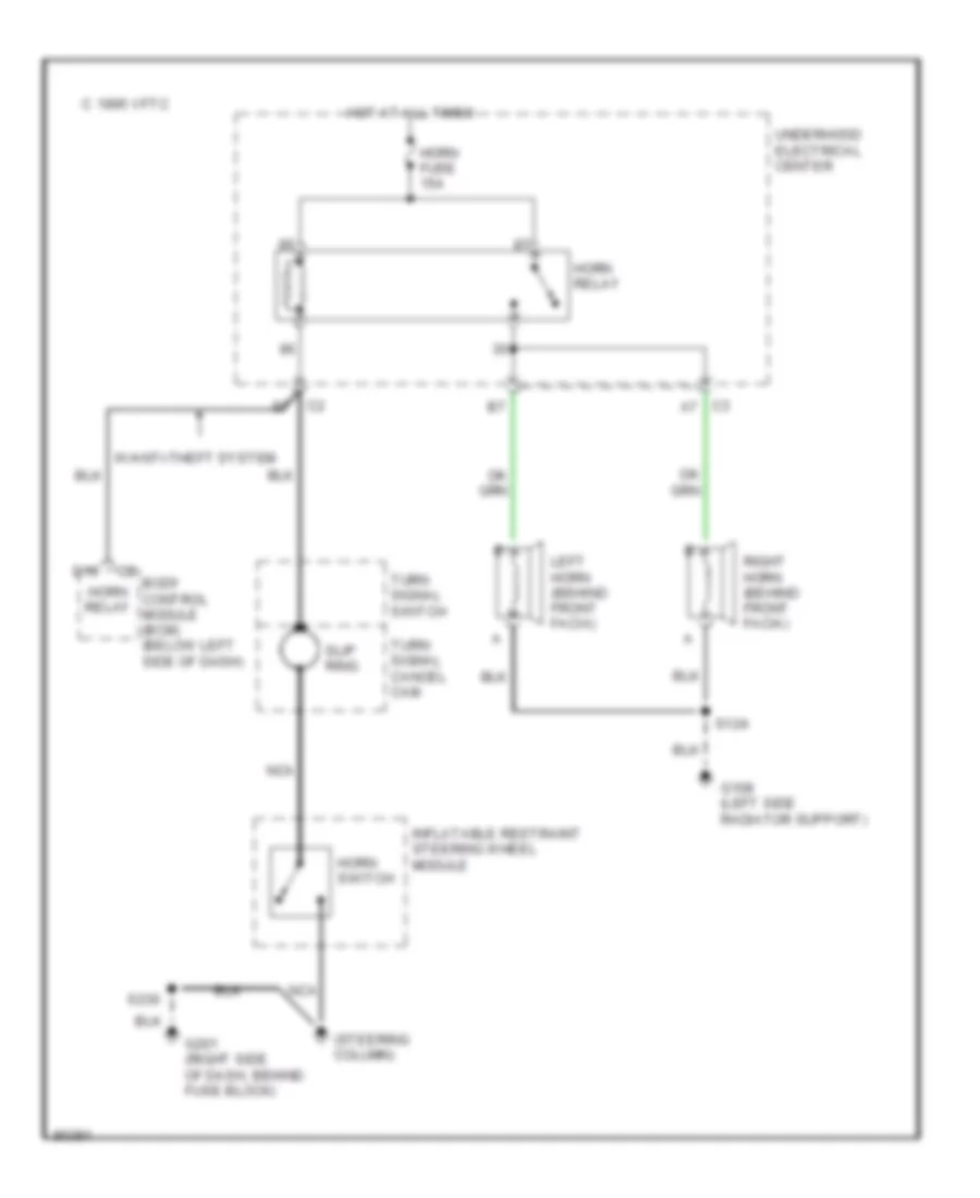
HORN Horn Wiring Diagram for Pontiac Grand Prix GTP 1997 List of elements for Horn Wiring Diagram for Pontiac Grand Prix GTP 1997: 22 (steering column) 1995 vftc c Body control module (bcm) (below left side of dash) C3 a7 D10 G108 (left side radiator support) G201 (right side of dash, behind fuse block) Horn fuse 15a Horn relay Horn switch Hot at all times Inflatable restraint steering wheel module Left horn (behind front facia) Nca Right horn (behind front facia) S124 S230 Slip ring Turn signal cancel cam Turn signal switch Underhood electrical center W/anti-theft system
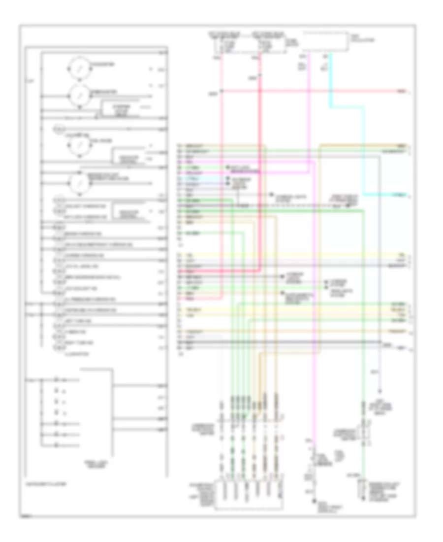
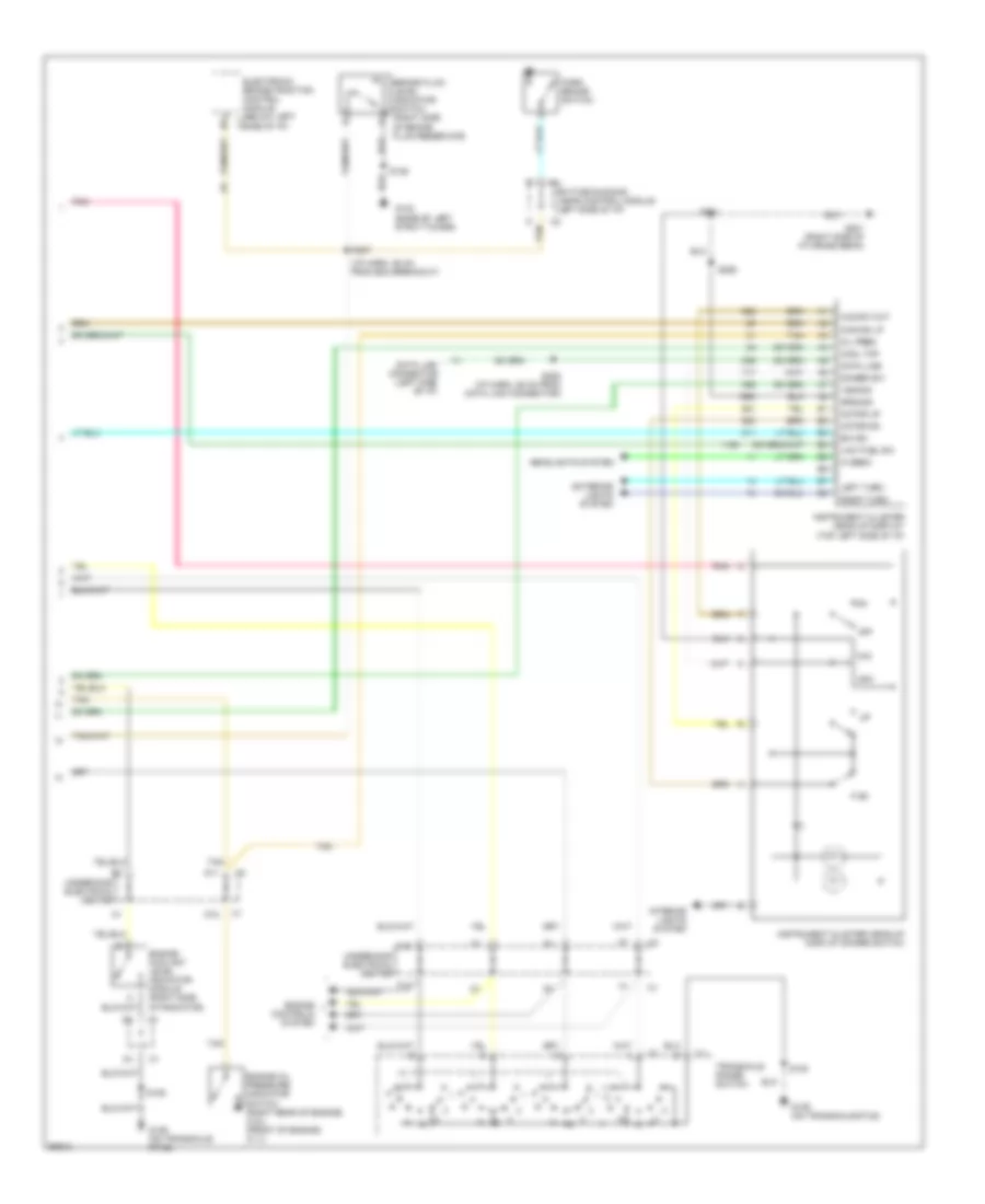
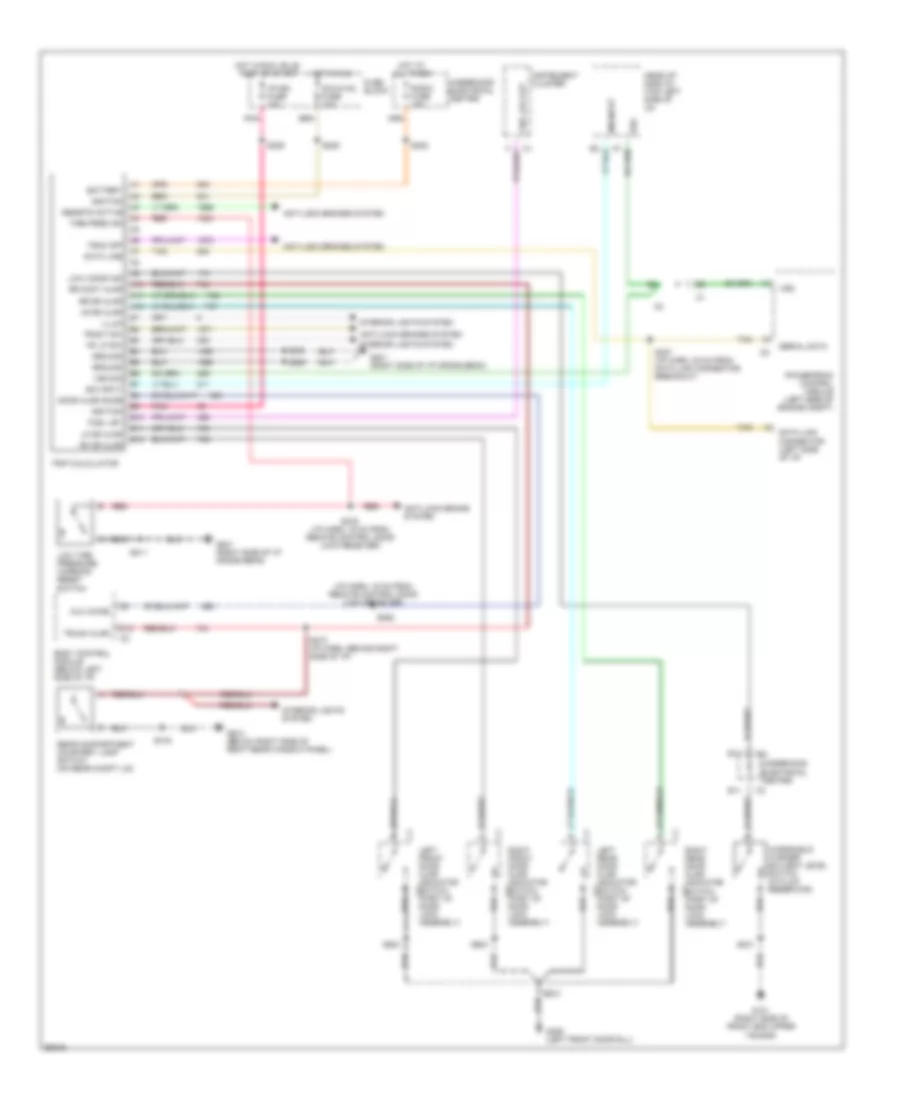
INSTRUMENT CLUSTER Driver Information Center Wiring Diagram for Pontiac Grand Prix GTP 1997 List of elements for Driver Information Center Wiring Diagram for Pontiac Grand Prix GTP 1997: 52 (i/p harn, 43 cm from bcm) (right side of i/p cross beam) g201 Anti-lock brake system Aux chime Body control module (below left side of i/p) Change oil soon ind Check tire pres ind D13 Driver information display E11 Fuse block G101 (right side of front end upper tie bar) G201 (right side of i/p cross beam) G309 (left front door sill) G403 (below right side of right rear window panel) Ground Hot in run, bulb test or start I/p-ign fuse 10a Interior lights system Left front door ajar Left front door ajar indicator switch c1 (part of door lock assembly) Left rear door ajar Left rear door ajar indicator switch (part of door lock assembly) Low tire pressure warning reset switch Low trac ind Low washer fluid ind Pnk Powertrain control module (left side of engine compt) Pwm dim input R/cmpt lid ajar ind Rear compartment courtesy lamp switch (on rear compt lid) Red Right front door ajar Right front door ajar indicator switch c1 (part of door lock assembly) Right rear door ajar Right rear door ajar indicator switch c1 (part of door lock assembly) S123 S209 S211 S230 S273 (i/p harn, behind right side of i/p) S276 (i/p harn, 16 cm from remote control door lock receiver) S279 S303 S416 S504 S604 Trac off ind Trac switch Trunk ajar Underhood electrical center Windshield washer solvent level switch (in fluid reservoir) Instrument Cluster Wiring Diagram (1 of 2) for Pontiac Grand Prix GTP 1997 List of elements for Instrument Cluster Wiring Diagram (1 of 2) for Pontiac Grand Prix GTP 1997: 84 (right side of i/p cross beam) g201 1-a 1-b 1-c 1-d 1-e 1-f 1-g 1-h 1-i 1-k 1-l 1-m 1-n 1-o 1-q 2-a 2-b 2-c 2-e 2-f 2-g 2-h 2-i 2-k 2-l 2-o 2-p 2-q 2-r Anti-lock brake system Anti-lock warning ind B10 Brake warning ind Btsi fuse 10a Charge Charge warning ind Cool temp Coolant warning ind D10 Engine coolant temperature gauge Engine coolant temperature sensor (top left side of engine) Exterior lights system Fasten belts warning ind Fuel gauge Fuel level sensor Fuel tank unit Fuse block G201 (right side of i/p cross beam) G316 (right front door sill) Headlights system Hi beam ind Hot in run, bulb test or start Illumination Indicator control Inflatable restraint warning ind Instrument cluster Interior lights system Interior lights system Ip ign fuse 10a Left turn ind Low coolant ind Low fuel ind Low oil Low oil level ind Mil ctrl Oil pressure warning ind Pnk Powertrain control module (left side of engine compt) Prndl logic decoder Right turn ind S209 S230 S264 S285 Service engine soon ind (mil) Speedometer Stepper motor drive Tach out Tachometer Tan Trip calculator Underhood electrical center Warning system Instrument Cluster Wiring Diagram (2 of 2) for Pontiac Grand Prix GTP 1997 List of elements for Instrument Cluster Wiring Diagram (2 of 2) for Pontiac Grand Prix GTP 1997: 51 (i/p harn, 36 cm from bcm breakout) A12 Brake fluid level indicator switch (right side of brake fluid reservoir) Chg ind lp Cool tmp D tan D11 D12 Data line Data link connector (left side of i/p) Daytime running lamps control module (left side of i/p) Dimmer sw E/m sw Electronic brake/traction control module (below left c1 side of i/p) Engine controls system Engine coolant level indicator module (right side of radiator) Engine oil pressure indicator switch (right rear of engine) (3.8l) (front of engine) (3.1l) Exterior lights system F12 G102 (base of left strut tower) G129 (on transaxle stud) G201 (right side of i/p cross beam) Ground Headlights system Hi beam Hud sw out Instrument cluster head-up display (top left side of i/p) Instrument cluster head-up display dimmer switch Interior lights system Left turn Low fuel sw Max Min Motor dn Motor up Off Oil pres Park brake switch Pnk Right turn S105 S106 S125 S207 S211 S225 (i/p harn, 25 cm from data link connector) S285 Tan Transaxle range switch Underhood electrical center Vss sig Trip Computer Wiring Diagram for Pontiac Grand Prix GTP 1997 List of elements for Trip Computer Wiring Diagram for Pontiac Grand Prix GTP 1997: 80 (i/p harn, 16 cm from remote control door lock receiver) A10 A11 A12 Abs/ets active Anti-lock brake system Anti-lock brakes system Aux chime B10 B11 B12 Battery Body control module (below left side of i/p) D13 Data line Data link connector (left side of i/p) Dic/hvac fuse 10a Door ajar chime E/m input E11 Fuel lev Fuel lev out Fuse block G101 (right side of front end upper tie bar) G201 (right side of i/p cross beam) G309 (left front door sill) G403 (below right side of right rear window panel) Ground Head-up display (top left side of i/p) Hot at all times Hot in run Hot in run, bulb test or start I/p-ign fuse 10a Ignition Illum Instrument cluster Interior lights system Left front door ajar indicator switch c1 (part of door lock assembly) Left rear door ajar indicator switch (part of door lock assembly) Lf dr ajar Low tire pressure warning reset switch Low wshr ind Lr dr ajar Pk lp sw Pnk Powertrain control module (left side of engine compt) Radio fuse 10a Rear compartment courtesy lamp switch (on rear compt lid) Red Rf dr ajar Right front door ajar indicator switch c1 (part of door lock assembly) Right rear door ajar indicator switch c1 (part of door lock assembly) Rr comt ajar Rr dr ajar S202 S206 S209 S211 S230 S231 S237 (i/p harn, 30 cm from data link connector breakout) S262 S273 (i/p harn, behind right side of i/p) S276 (i/p harn, 16 cm from remote control door lock receiver) S285 S303 S416 S504 S604 Serial data Tan Tire pres ind Trac off Tract sw Trip calculator Trunk ajar Underhood electrical center Vss Vss sig Windshield washer solvent level switch (in fluid reservoir)
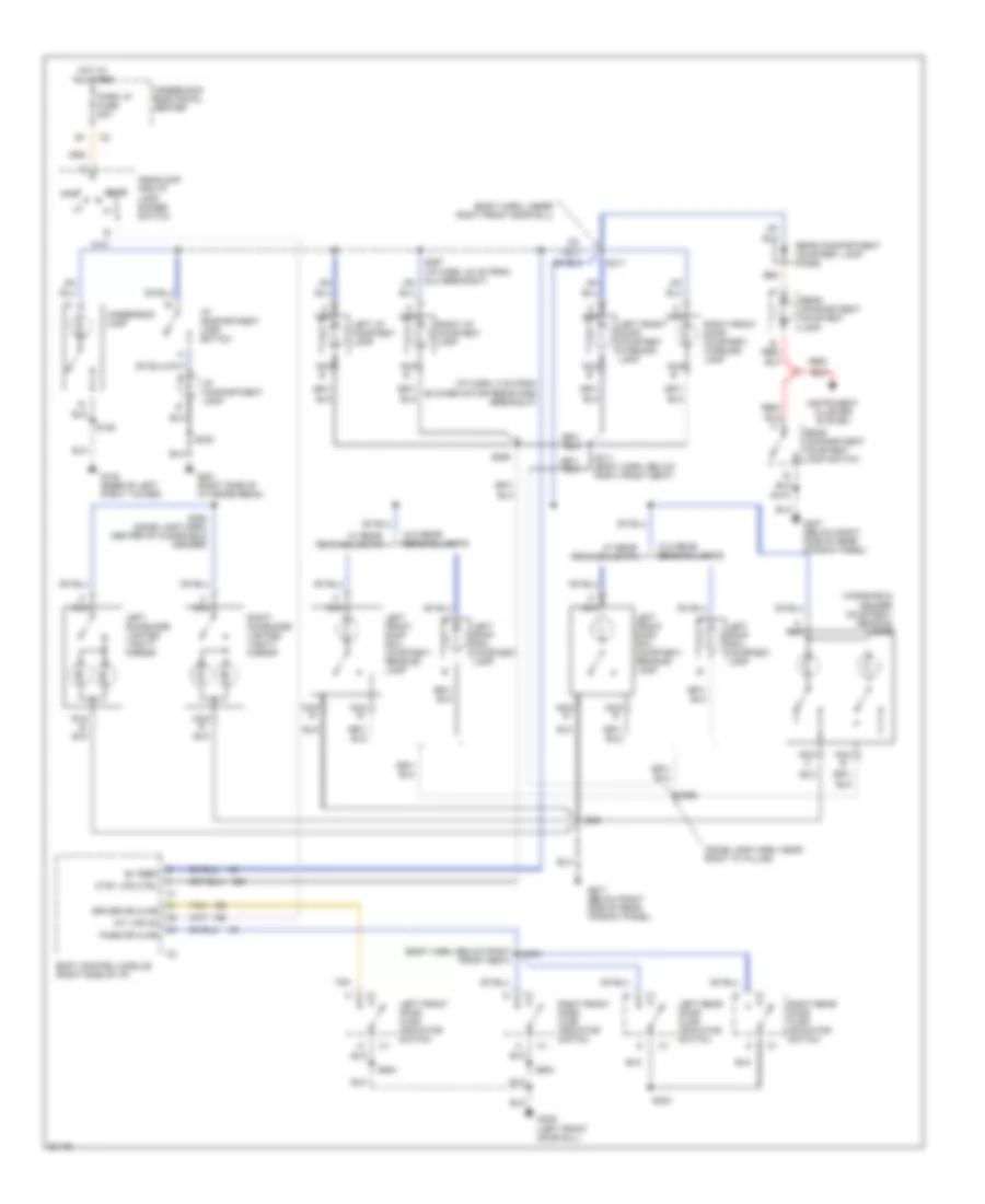
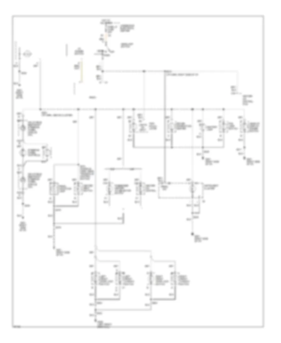
INTERIOR LIGHTS Courtesy Lamps Wiring Diagram for Pontiac Grand Prix GTP 1997 List of elements for Courtesy Lamps Wiring Diagram for Pontiac Grand Prix GTP 1997: 61 (body harn, below right front seat) (body harn, under right front door sill) (dome lamp harn, near right "c" pillar) (i/p harn, 8 cm from blower motor resistors breakout) A nca B+ feed Body control module (right side of i/p) Ctsy lps ctrl Dome Driver dr ajar G102 (base of left strut tower) G201 (right side of i/p cross beam) G307 (below right side of rear window panel) G309 (left front door sill) Headlamp and i/p lamp dimmer switch Hot at all times I/p compartment lamp I/p compartment lamp switch Instrument cluster system Int lps on Left roof rail courtesy lamp Left front door ajar indicator switch Left front door courtesy warning lamp Left front roof rail courtesy/ reading lamp Left i/p courtesy lamp Left rear door ajar indicator switch Left sunshade lighted vanity mirror Nca Nca b Nca c Off Park lp fuse 20a Pass dr ajar Rear compartment courtesy lamp Rear compartment courtesy lamp diode Rear compartment courtesy lamp switch Red/ Right front door ajar indicator switch Right front door courtesy warning lamp Right i/p courtesy lamp Right rear door ajar indicator switch Right sunshade lighted vanity mirror S125 S230 S259 S303 S309 S311 (body harn, below right front seat) S317 S390 S393 (dome lamp harn, center of windshield header) S398 S416 S504 S604 Tan Underhood electrical center Underhood lamp W/ rear reading lights W/o rear reading lights Windshield header courtesy/ reading lamps Instrument Illumination Wiring Diagram for Pontiac Grand Prix GTP 1997 List of elements for Instrument Illumination Wiring Diagram for Pontiac Grand Prix GTP 1997: 44 (i/p harn, right side of i/p) Ashtray lamp C16 Cj2 Driver information center Fog lamp switch G201 (right side of i/p) G309 (left front door sill) Head Head-up display dimmer switch Headlamp switch Heated seat switch Heater- a/c control Heater- a/c control (cj2) Hot at all times I/p dimmer switch Inflatable restraint steering wheel module coil Instrument cluster Left front door lock switch Left front window switch Lights on input Nca Off Park Park lp fuse 20a Passenger heater- a/c selector switch Prndl dim Prndl indicator lamp Radio Right front door lock switch Right front window switch S203 (i/p harn, above cluster) S211 S212 S230 S303 S374 (console harn, near transaxle control switch) S375 S504 S604 Steering wheel controls Trip calcu- lator U40 Underhood electrical center
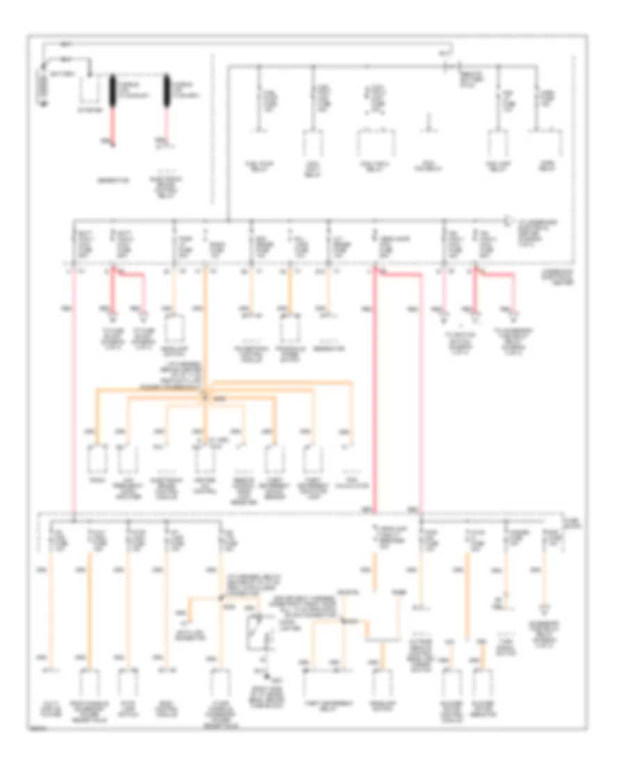
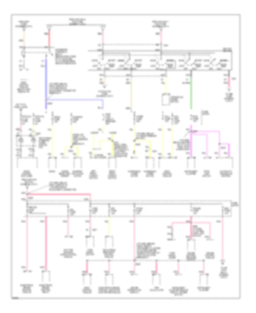
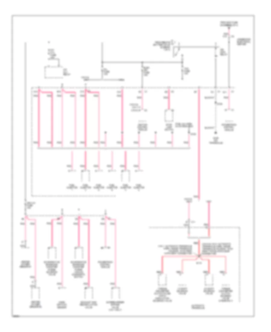
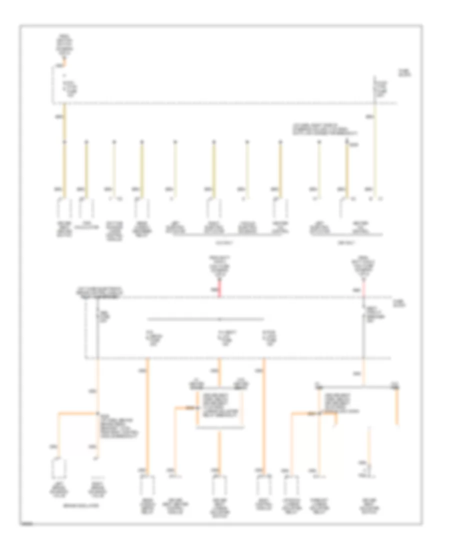
POWER DISTRIBUTION Power Distribution Wiring Diagram (1 of 4) for Pontiac Grand Prix GTP 1997 List of elements for Power Distribution Wiring Diagram (1 of 4) for Pontiac Grand Prix GTP 1997: 85 (c60) (cj2) (i/p harness, behind center of i/p, 17 cm from data link connector breakout) (i/p harness, below center of i/p, 27 cm from 10-pin clear connector) (right side of i/p cross beam, behind fuse block) A12 Accessory time delay relay (diagram 2 of 4) Alt sense fuse 10a Aux/ cnsl fuse 15a B/u lamp fuse 10a B12 Base Batt main 1 maxi fuse 60a Batt main 2 maxi fuse 60a Battery Blower motor control module Blower motor resistor Body control module C60 Cd chg fuse 10a Cig ltr fuse 15a Cigar lighter Cj2 Cool fan 1 maxi fuse 30a Cool fan 1 relay Cool fan 2 maxi fuse 30a Cool fan 2 relay Cool fan relay Data link connector E c12 E12 Ecm sense fuse 10a Electronic brake control module Electronic brake control relay Floor console accessory power receptacle Fog lamp relay Fog lp fuse 10a Fuel pump fuse 15a Fuel pump relay Fuse block Fusible link (10 ga-rust) G201 Generator Hazard fuse 15a Headlamp circuit breaker 20a Headlamp switch Headlamps maxi fuse 60a Heater- a/c control Horn fuse 15a Horn relay Hvac hi fuse 30a Ign main 1 maxi fuse 40a Ign main 2 maxi fuse 60a Int lamp fuse 10a Low frequency audio amplifier Multi disc cd player Outside remote control rear view mirror switch Park lp fuse 20a Powertrain control module Pwr mir fuse 10a Radio Radio fuse 10a Rap fuse 10a Red Remote battery stud Remote control door lock receiver Roof console accessory power receptacle S202 S238 S331 Starter Stop lamp fuse 15a Stop lamp switch Theft deterrent indicator lamp Theft deterrent relay Theft deterrent shock sensor To accessory time delay relay (diagram 2 of 4) To fuse block (diagram 4 of 4) To ignition switch (diagram 2 of 4) To underhood electrical center (diagram 3 of 4) Transaxle range switch Trip calculator Turn signal switch Underhood electrical center Uplevel (driver seat harness, under right front door sill, 14 cm from 6-pin black connector) Power Distribution Wiring Diagram (2 of 4) for Pontiac Grand Prix GTP 1997 List of elements for Power Distribution Wiring Diagram (2 of 4) for Pontiac Grand Prix GTP 1997: 86 (2 door) c1 (4 door) (dome lmp harn, 11 cm from reading lamp breakout) (i/p harn, behind right side of instrument cluster, 20 cm from driver information display/ trip calculator breakout) (i/p harn, below center of i/p, 34 cm from 10-pin clear conn) (i/p harn, below i/p, near steering column) (i/p harn, below right side of i/p, 1 cm from 56-pin black/gray connector) (i/p harn, below right side of i/p, 8 cm from 56-pin black/gray connector breakout) 2 door 4 door Abs ign fuse 10a Accessory time delay relay (behind right side of i/p, mounted to i/p cross beam above fuse block) Accy Automatic transaxle control Body control module Body control module (below left side of i/p) Btsi fuse 10a Bulb test C13 C201 C205 Cruise control module Cruise control release switch Cruise fuse 10a Daytime running lamps control module Driver information display Drl fuse 10a Ecm fuse 10a Electronic brake control indicator lamp driver module Electronic brake control module Electronic brake control relay From ign main 1 maxi fuse (diagram 1 of 4) From ign main 2 maxi fuse (diagram 1 of 4) From ignition switch (diagram 2 of 4) From rap fuse (diagram 1 of 4) Fuse block H c Hot with park lamps on I/p-ign fuse 10a Ignition switch Inflatable restraint control module Inflatable steering wheel module coil Inside rear view mirror Instrument cluster Instrument cluster head-up display dimmer switch Left front window switch Lock Mall fuse 10a Mall pgm fuse 10a Nca Off Pnk Pwr wdo circuit breaker 30a Radio Radio control switches Radio fuse 10a Red Right front window switch Run S209 S220 S228 S249 S264 S266 (i/p harn, 21 cm from stop lamp switch) S310 (body harn, under right frt door sill, 14 cm from 16-pin white connector) S376 S394 Sir fuse 15a Start Stop lamp switch Str whl ctrl fuse 2a Str whl illum fuse 2a Sunroof actuator motor Sunroof fuse 20a To abs fuse (diagram 2 of 4) To dic/hvac fuse (diagram 4 of 4) To ign main relay (diagram 3 of 4) Transaxle range switch Trip calculator Turn fuse 10a Turn signal lever Turn signal switch Windshield wiper motor Windshield wiper switch Wiper fuse 25a Power Distribution Wiring Diagram (3 of 4) for Pontiac Grand Prix GTP 1997 List of elements for Power Distribution Wiring Diagram (3 of 4) for Pontiac Grand Prix GTP 1997: 50 (fuel inj harn, 44 cm from pcm) (vin 1: automatic transaxle harn, inside transaxle housing, 19 cm from 14-pin gray connector) (vin k & (vin m & vin k: automatic transaxle harn, inside transaxle housing, 19 cm from 7-pin black/clear connector) 1-2 shift solenoid valve 2-3 shift solenoid valve A/c clu fuse 10a A/c clu relay A12 Automatic transaxle B (vin m) B12 C11 C12 D11 Elek ign fuse 15a Evaporative emissions canister purge solenoid valve Evaporative emissions canister purge vacuum diagnostic switch Exhaust gas recirculation valve From ecm fuse (diagram 2 of 4) From remote l battery stud (diagram 1 of 4) Fuel injector G129 (on transaxle) Heated oxygen sensor #1 Heated oxygen sensor #2 Ign main relay Ign1-uh fuse 15a Ignition control module Inj fuse 10a Mass air flow sensor Nca P vin 1) Pnk Pnk c10 Powertrain control module Red Red a S106 S109 S115 Stop lamp switch Supercharger bypass valve (vin 1 only) Tcc fuse 10a Torque converter clutch pulse width modulation solenoid valve Torque converter clutch solenoid valve (4t60e-only) Underhood electrical center Vin 1 Vin k & vin 1 Vin k & vin m Vin m Power Distribution Wiring Diagram (4 of 4) for Pontiac Grand Prix GTP 1997 List of elements for Power Distribution Wiring Diagram (4 of 4) for Pontiac Grand Prix GTP 1997: 44 (driver seat harn, below driver seat, 10 cm from lumbar adjuster relay breakout) (driver seat harn, below driver seat, 36 cm from 6-pin black conn) (i/p harn, right side of steering column, 4 cm from data link connector breakout) Abs fuse 20a Body control module Brake modulator C60 only Cj2 only Daytime running lamps control module Dic/ hvac fuse 10a Driver seat adjuster switch Driver seat heated switch Driver seat heater control module Driver seat lumbar adjuster switch Fore/aft lumbar adjuster relay From batt main 2 maxi fuse (diagram 1 of 4) From ignition switch (diagram 2 0f 4) Fuse block H seat/ lum fuse 15a Heater- a/c control Hot when electronic brake control module relay is energized Hvac ctrl fuse 20a Left brake solenoid valve Left electric actuator Nca Pwr lock fuse 15a R defog fuse 30a Rear window defog relay Rear window defogger relay Red Right brake solenoid valve Right electric actuator S206 S235 (i/p harn, behind brake pedal bracket, 15 cm from body control module breakout) S331 S332 Seat circuit breaker 25a Trip calculator Up/down lumbar adjuster relay Vacuum electric solenoid W/ ags W/ heated seats W/o ags W/o heated seats
POWER DOOR LOCKS Power Door Lock Wiring Diagram for Pontiac Grand Prix GTP 1997 List of elements for Power Door Lock Wiring Diagram for Pontiac Grand Prix GTP 1997: 56 (not used) (w/ rke only) Accy 1 B/u lamp fuse 10a Battery Battery (b+) Body control module (behind left side of dash, left side of steering column) C13 Door lk (batt) Door lock Door unlk cyl Door unlock Drvr dr unlk Fuse block (right side of dash) G201 (right side of i/p cross beam, behind fuse block) G309 (left door sill) Ground Hot at all times Hot in accy or run Hot in run, bulb test or start I/p-ign fuse 10a Ignition 1 Int lamp fuse 10a Interior lights system Left front door lock actuator Left front door lock switch Left key cylinder lock switch assembly (left front door) Left rear door lock actuator Lock Mall fuse 10a Nca Park input Pass dr unlk Pnk Pwr lock fuse 15a Radio fuse 10a Remote control door lock receiver (rke) (behind left side of dash, behind driver info center) Rfa link Right front door lock actuator Right front door lock switch Right key cylinder lock switch assembly (right front door) Right rear door lock actuator Rr lid release S202 S209 S285 S303 (body harness, under left front seat) S314 (body harness, under right front seat) S315 (body harness, under right front seat) S504 (left front door harness, 6cm from left door lock switch breakout) Switch breakout) s504 Tan Transaxle range switch (on transaxle) Trunk, tailgate, fuel doors system Underhood electrical center (right side of engine compartment) Unlock
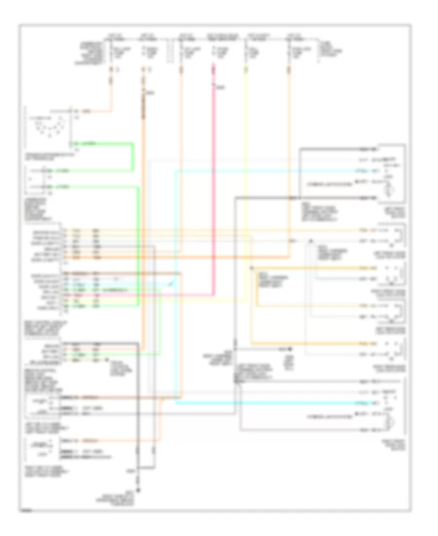
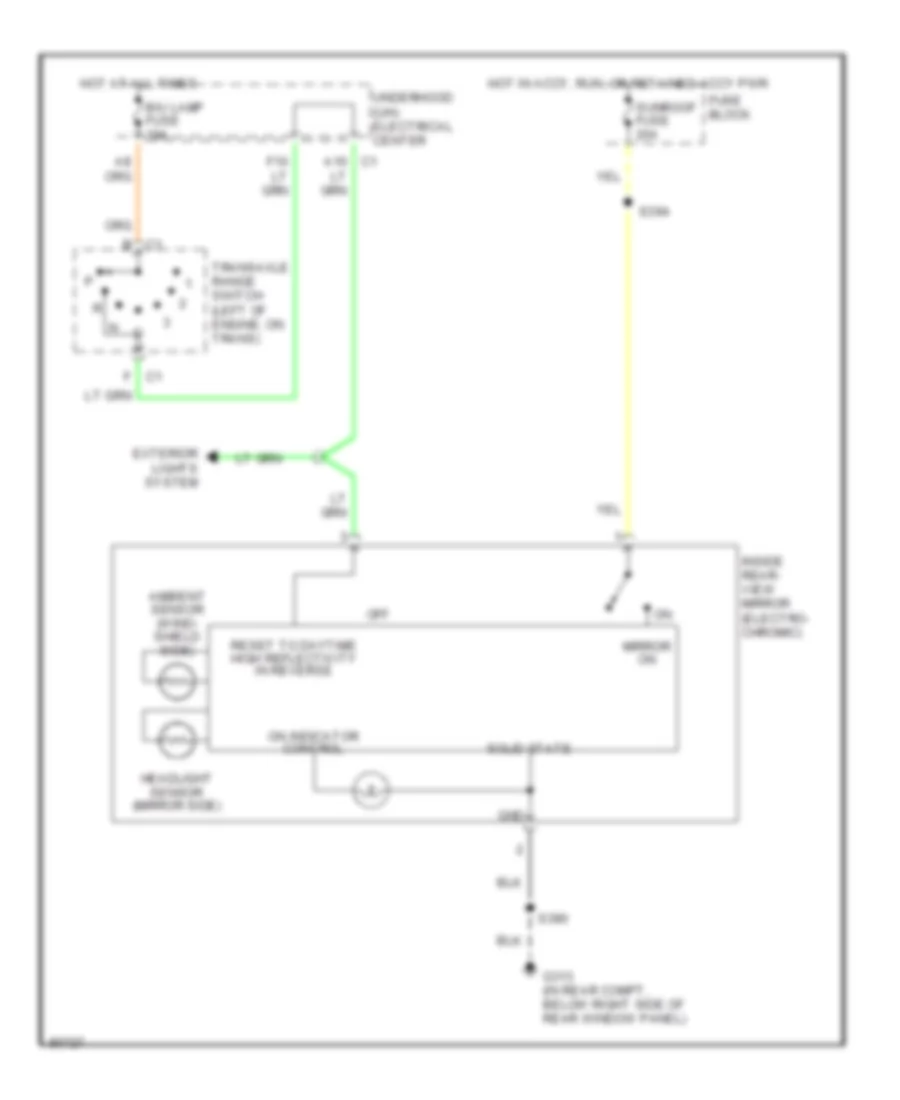
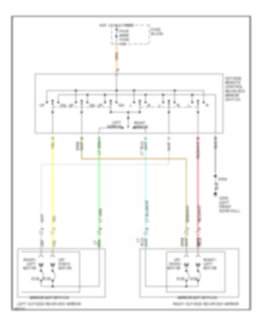
POWER MIRRORS Electrochromic Mirror Wiring Diagram for Pontiac Grand Prix GTP 1997 List of elements for Electrochromic Mirror Wiring Diagram for Pontiac Grand Prix GTP 1997: 23 A10 c1 Ambient sensor (wind- shield side) B c1 B/u lamp fuse 10a Exterior lights system F c1 Fuse block G313 (in rear compt, below right side of rear window panel) Gnd Headlight sensor (mirror side) Hot at all times Hot in accy, run, or retained accy pwr Inside rear- view mirror (electro- chromic) Mirror on Off On indicator control Reset to daytime high reflectivity in reverse S390 S394 Solid state Sunroof fuse 20a Transaxle range switch (left of engine, on trans) Underhood (uh) electrical center Power Mirrors Wiring Diagram for Pontiac Grand Prix GTP 1997 List of elements for Power Mirrors Wiring Diagram for Pontiac Grand Prix GTP 1997: 14 Ecb Fuse block G309 (left front door sill) Hot at all times Left mirror Left outside rearview mirror Mirror motor pack Outside remote control rearview mirror switch Pwr mirr fuse 10a Right mirror Right outside rearview mirror Right/ left motor S504 Up/ down motor
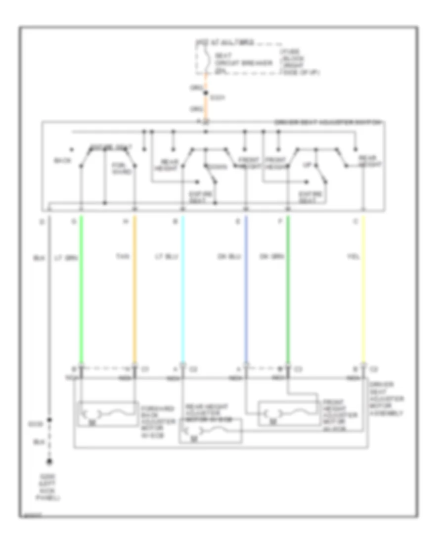
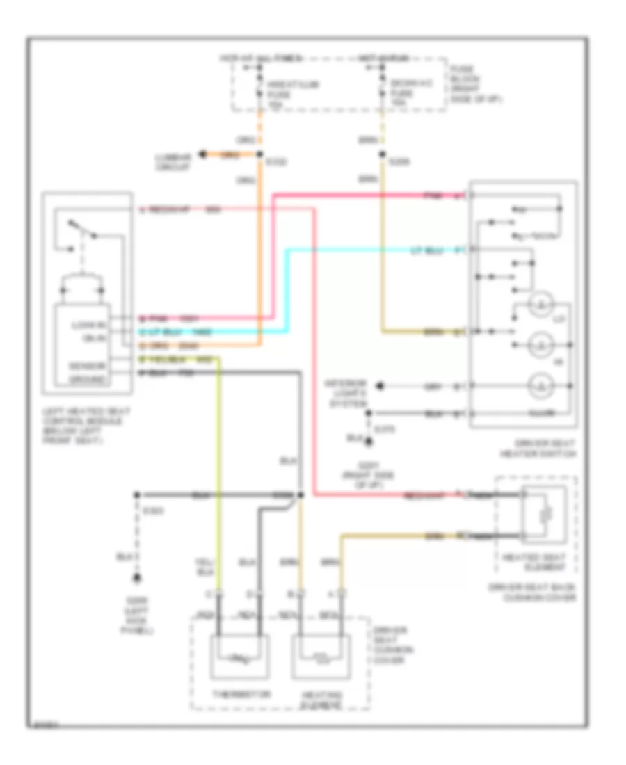
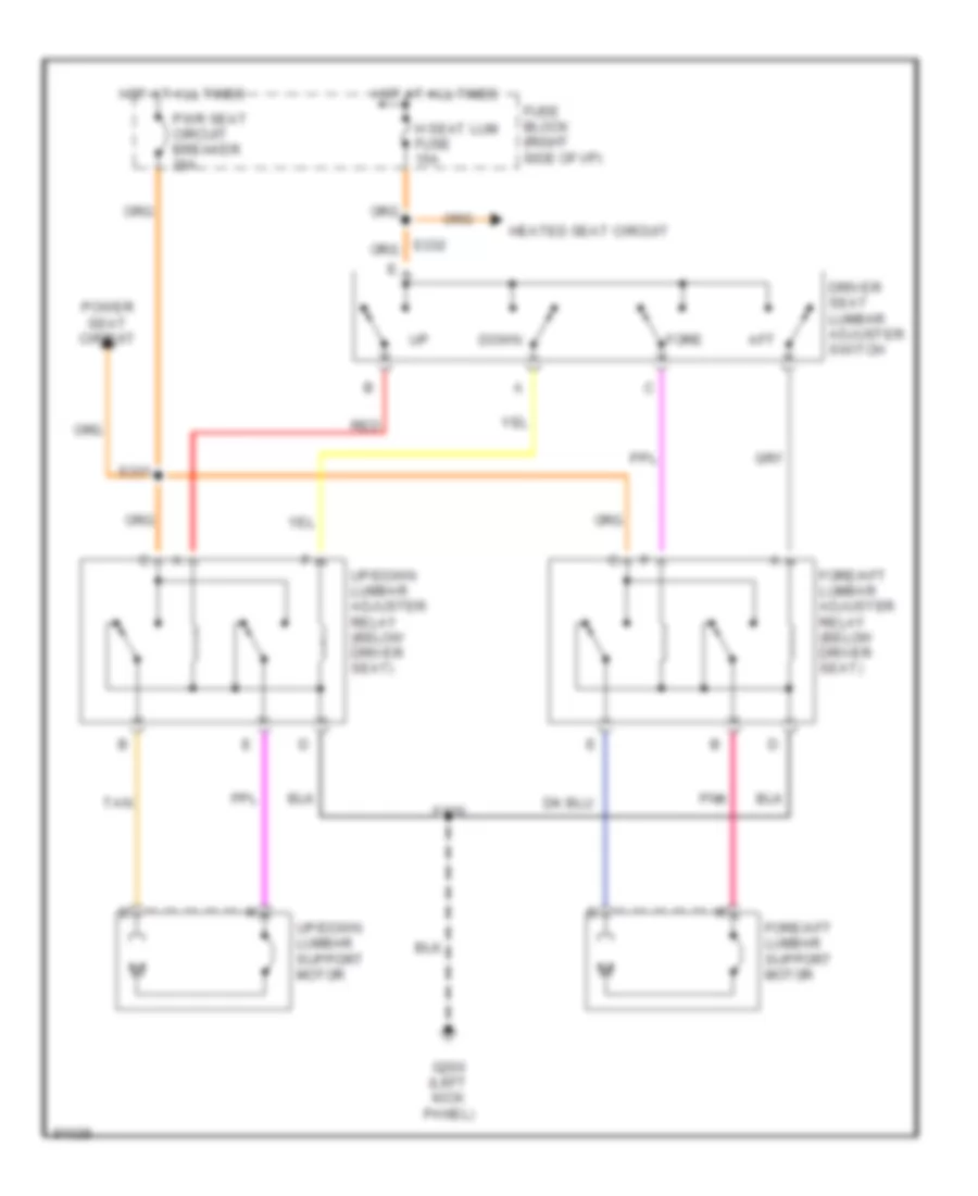
POWER SEATS 6-Way Power Seat Wiring Diagram for Pontiac Grand Prix GTP 1997 List of elements for 6-Way Power Seat Wiring Diagram for Pontiac Grand Prix GTP 1997: 19 Back Down Driver seat adjuster motor assembly Driver seat adjuster switch Entire seat For- ward Forward/ back adjuster motor w/ ecb Front height Front height adjuster motor w/ ecb Fuse block (right side of i/p) G200 (left kick panel) Hot at all times Nca Rear height Rear height adjuster motor w/ ecb S330 S331 Seat circuit breaker 25a Tan Driver Heated Seat Wiring Diagram for Pontiac Grand Prix GTP 1997 List of elements for Driver Heated Seat Wiring Diagram for Pontiac Grand Prix GTP 1997: 29 Dic/hvac fuse 10a Driver seat back cushion cover Driver seat cushion cover Driver seat heater switch Fuse block (right side of i/p) G200 (left kick panel) G201 (right side of i/p) Ground Heated seat element Heating element Hot at all times Hot in run Hseat/lum fuse 15a Illum Interior lights system Left heated seat control module (below left front seat) Lo/hi in Lumbar circuit Nca On in Pnk Pnk b S206 S303 S330 S332 S375 Sensor Thermistor Lumbar Wiring Diagram for Pontiac Grand Prix GTP 1997 List of elements for Lumbar Wiring Diagram for Pontiac Grand Prix GTP 1997: 20 Aft Down Driver seat lumbar adjuster switch Fore Fore/aft lumbar adjuster relay (below driver seat) Fore/aft lumbar support motor Fuse block (right side of i/p) G200 (left kick panel) H seat lum fuse 15a Heated seat circuit Hot at all times Pnk Power seat circuit Pwr seat circuit breaker 25a Red S330 S331 Tan Up/down lumbar adjuster relay (below driver seat) Up/down lumbar support motor
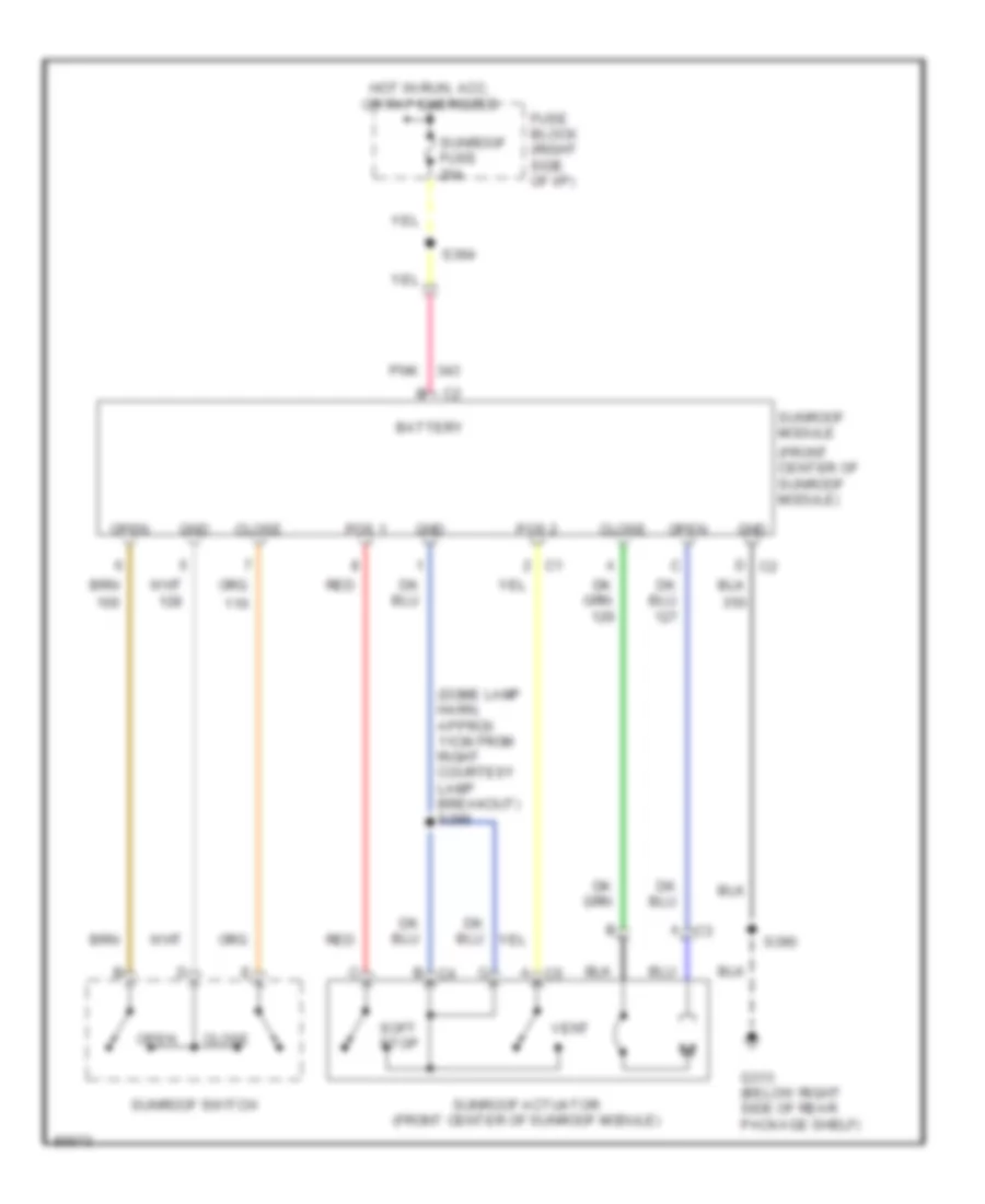
POWER TOP/SUNROOF Sunroof Wiring Diagram for Pontiac Grand Prix GTP 1997 List of elements for Sunroof Wiring Diagram for Pontiac Grand Prix GTP 1997: 21 (dome lamp harn, approx 11cm from right courtesy lamp breakout) s399 (front center of sunroof module) Battery Close Fuse block (right side of i/p) G313 (below right side of rear package shelf) Gnd Hot in run, acc, or rap energized Open Pnk Pos 1 Pos 2 Red S390 S394 Soft stop Sunroof actuator (front center of sunroof module) Sunroof fuse 20a Sunroof module Sunroof switch Vent
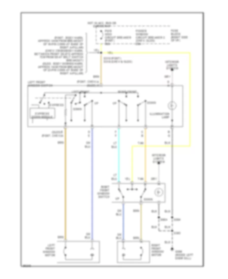
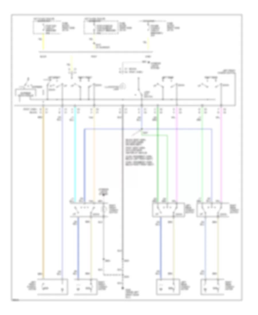
POWER WINDOWS Power Window Wiring Diagram, 2 Door for Pontiac Grand Prix GTP 1997 List of elements for Power Window Wiring Diagram, 2 Door for Pontiac Grand Prix GTP 1997: 27 (olds) (pont, chev) h g (pont: body harn, approx 14cm from breakout of 16-pin conn at base of right a-pillar) (chev: crossbody harn, between front seats approx 7cm from seat belt switch breakout) (olds: body woring harn, approx 14cm from breakout of 23-pin conn at base of right a-pillar) A (pont, chev) D a Down E (olds) Express Express down module Fuse block (right side of i/p) G309 (inside left door sill) Hot in acc, run or during rap Illumination lamp Interior lights system Left front Left front window motor Left front window switch Power window circuit breaker c (chev, olds) 20a Pwr wdo circuit breaker (pont) 30a Right front Right front window motor Right front window switch S303 S310 (pont) s318 (chev & olds) S504 S604 Tan Power Window Wiring Diagram, 4 Door for Pontiac Grand Prix GTP 1997 List of elements for Power Window Wiring Diagram, 4 Door for Pontiac Grand Prix GTP 1997: 41 (buick) (buick: body harn, on floor under driver's seat) (chev: crossbody harn below right front seat) (olds: crossbody harn, below left front seat) (pont, chev) (pont: body harn, on floor near center of vehicle) Buick Chev Down Ecb Express Express down module Fuse block (right side of i/p) G309 (inside left front door sill) Hot in acc, run or during rap Hot in run Illumination lamp Interior lights system Left front Left front window motor Left front window switch Left rear Left rear window motor Left rear window switch Lock out switch Pont Power window circuit breaker c 20a Pwr wdo circuit breaker 30a Pwr windows pwr sunroof circuit breaker 30a Right front Right front window motor Right front window switch Right rear Right rear window motor Right rear window switch S303 S307 S410 (w/ sunroof) S504 S604 Tan
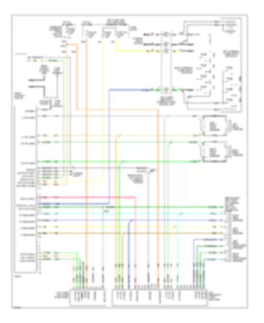
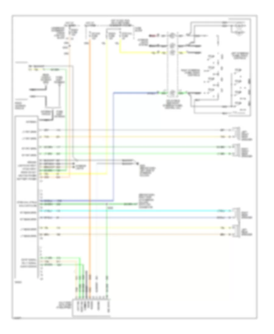
RADIO Radio Wiring Diagrams, with Amplifier for Pontiac Grand Prix GTP 1997 List of elements for Radio Wiring Diagrams, with Amplifier for Pontiac Grand Prix GTP 1997: 83 (behind dash, left side of steering column) (behind dash, right side of steering column) data link connector A10 A11 A12 Amp on input Antenna Antenna module Audio common B red B10 B11 B12 Bare Battery power Cd chg fuse 10a Cd lt signal Cd rt signal Common Drain E & c dataline E&c data F7 c2 Fixed mast antenna Fuse block G202 Ground Hot at all times Hot in acc, run or w/ retained accessory power Ign power Ignition power Inflatable restraint steering wheel control coil Interior lights Interior lights system Left front door speaker Left front tweeter Left rear speaker Left rear subwoofer speaker Left sig Left steering wheel radio controls Lights on input Low frequency audio amplifier Lr sub Lt frt Lt frt spkr Lt rear Lt rear spkr Multi-disc cd player (if equipped) Nca Pnk Power Radio Radio antenna module Radio fuse 15a Radio on Radio on out Rear window antenna grid Right front door speaker Right front tweeter Right rear speaker Right rear subwoofer speaker Right sig Right steering wheel radio controls Rr sub Rt frt Rt frt spkr Rt rear Rt rear spkr S202 S225 Str whl fuse 2a Strg whl ctrls Sw 1 Sw 2 Sw 3 Sw 4 Sw 5 Sw 6 Sw 7 Sw 8 Tan Underhood accessory wiring junction block Vf dim input Radio Wiring Diagrams, without Amplifier for Pontiac Grand Prix GTP 1997 List of elements for Radio Wiring Diagrams, without Amplifier for Pontiac Grand Prix GTP 1997: 61 (behind dash, right side of steering column) data link connector Antenna Antenna module Audio common B red Bare Battery power Cd chg fuse 10a Cd lt signal Cd rt signal Common Drain E & c dataline E&c data F7 c2 Fixed mast antenna Fuse block G202 (behind dash, left side of steering column) Ground Hot at all times Hot in acc, run or w/ retained accessory power Ignition power Inflatable restraint steering wheel control coil Interior lights Interior lights system Left front rear speaker Left rear speaker Left sig Left steering wheel radio controls Lights on input Lt frt spkr Lt rear spkr Multi-disc cd player (if equipped) Nca Power Radio Radio antenna module Radio fuse 15a Radio on out Rear window antenna grid Right front rear speaker Right rear speaker Right sig Right steering wheel radio controls Rt frt spkr Rt rear spkr S202 S225 Str whl fuse 2a Strg whl ctrls Sw 1 Sw 2 Sw 3 Sw 4 Sw 5 Sw 6 Sw 7 Sw 8 Tan Underhood accessory wiring junction block Vf dim input
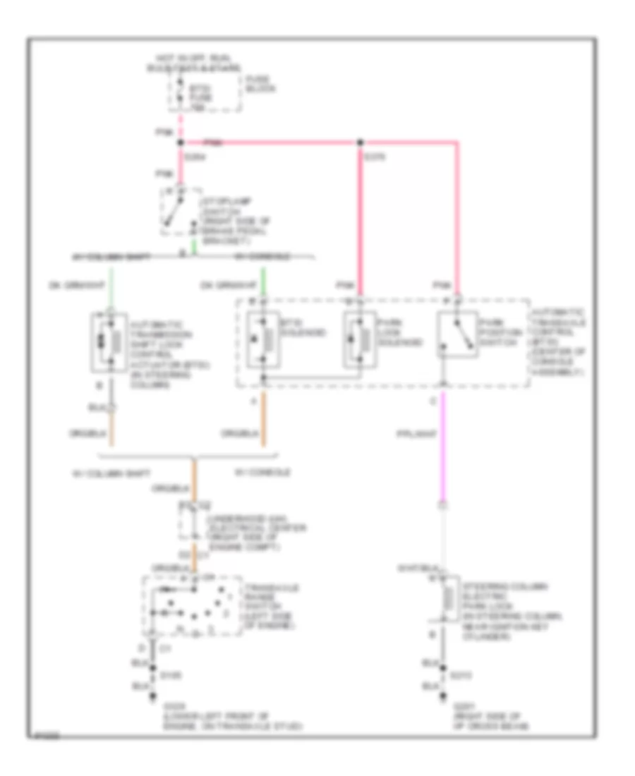
SHIFT INTERLOCKS Shift Interlock Wiring Diagram for Pontiac Grand Prix GTP 1997 List of elements for Shift Interlock Wiring Diagram for Pontiac Grand Prix GTP 1997: 23 Automatic tranmission shift lock control actuator (btsi) (in steering column) Automatic transaxle control (btsi) (center of console assembly) B3 c2 Btsi fuse 10a Btsi solenoid D2 c1 Fuse block G129 (lower left front of engine, on transaxle stud) G201 (right side of i/p cross beam) Hot in off, run, bulb test & start Park lock solenoid Park position switch Pnk S105 S213 S264 S376 Steering column electric park lock (in steering column, near ignition key cylinder) Stoplamp switch (right side of brake pedal bracket) Transaxle range switch (left side of engine) Underhood (uh) electrical center (right side of engine compt) W/ column shift W/ console
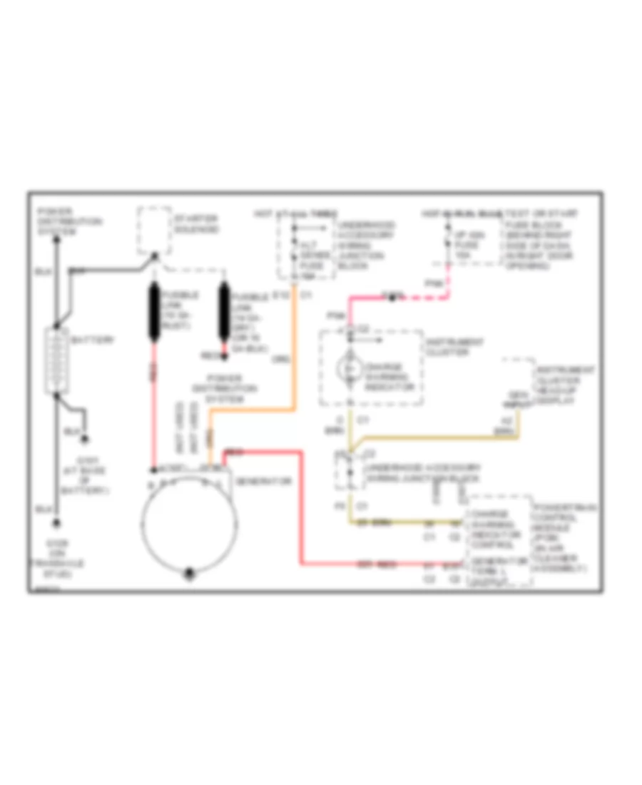
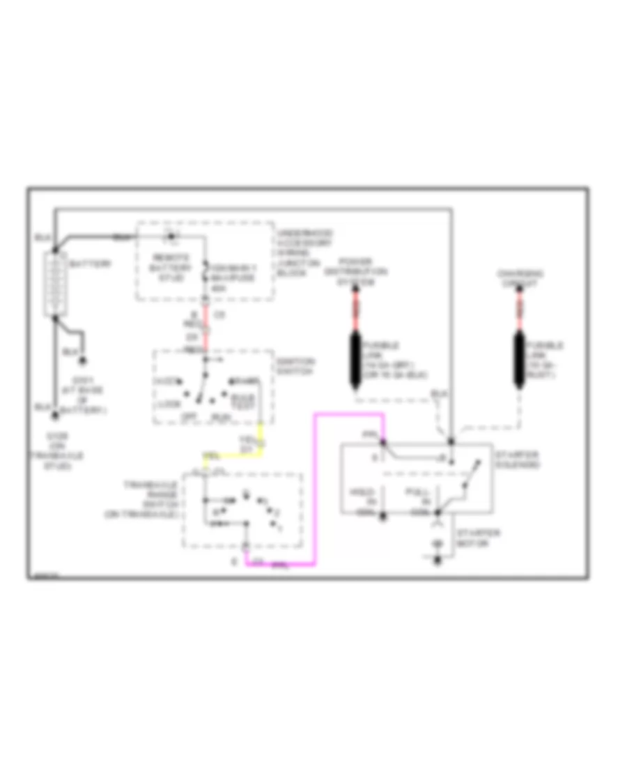
STARTING/CHARGING Charging Wiring Diagram for Pontiac Grand Prix GTP 1997 List of elements for Charging Wiring Diagram for Pontiac Grand Prix GTP 1997: 32 (1997) (1998) (not used) a (not used) c Alt sense fuse 10a B + B35 Battery Charge warning indicator Charge warning indicator control E12 c1 F p F5 c1 Fuse block (behind right side of dash, in right door opening) Fusible link (10 ga- rust) G101 (at base of battery) G129 (on transaxle stud) Gen input Generator Generator term. l output Hot at all times Hot in run, bulb test or start I/p ign fuse 10a Instrument cluster Instrument cluster head-up display Pnk Power distribution system Powertrain control module (pcm) (in air cleaner assembly) Red S209 Starter solenoid Underhood accessory wiring junction block Starting Wiring Diagram for Pontiac Grand Prix GTP 1997 List of elements for Starting Wiring Diagram for Pontiac Grand Prix GTP 1997: 23 Accy B red Battery Bulb test Charging circuit Fusible link (10 ga- rust) G101 (at base of battery) G129 (on transaxle stud) Hold- in coil Ign main 1 maxifuse 40a Ignition switch Lock Off Power distribution system Pull- in coil Red Remote battery stud Run Start Starter motor Starter solenoid Transaxle range switch (on transaxle) Underhood accessory wiring juncton block
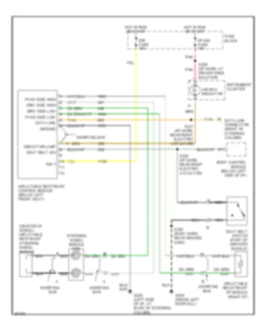
SUPPLEMENTAL RESTRAINTS Supplemental Restraint Wiring Diagram for Pontiac Grand Prix GTP 1997 List of elements for Supplemental Restraint Wiring Diagram for Pontiac Grand Prix GTP 1997: 35 (center of wheel) inflatable restraint steering wheel module Air bag indicator B nca Bar Body control module (below left side of i/p) Data line Data link connector (right of steering column) Driv side high Driv side low Fuse block G202 (left side of i/p, at base of steering column) G309 (inside left door sill) Ground Hot in run or start I/p-ign fuse 10a Ign 1 Indicator lamp Inflatable reastraint i/p module (right i/p) Inflatable restraint control module (below left front seat) Instrument cluster Nca Pass side high Pass side low Pnk S209 (i/p harn, at driver knee bolster) S226 (i/p harn, near right electric actuator) S237 (i/p harn, near right electric actuator) S305 (body harn, near ground g309) Seat belt sig Seat belt switch (part of driver's buckle) Shorting Shorting bar Sir fuse 15a Steering wheel module coil Tan
TRANSMISSION
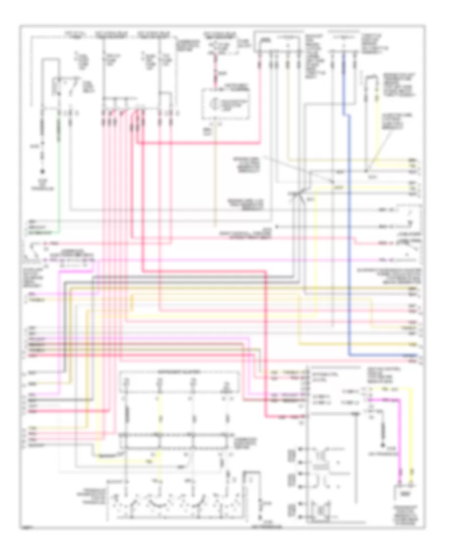
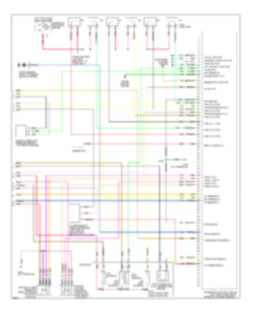
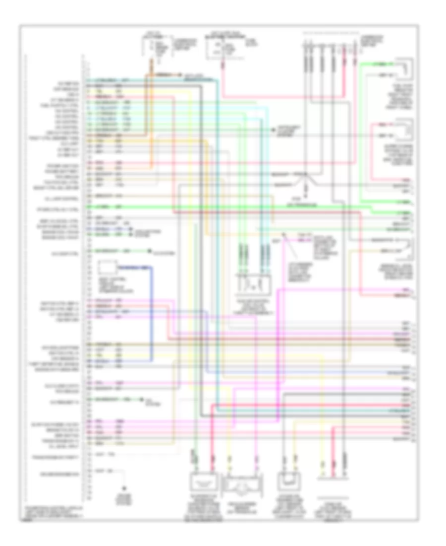
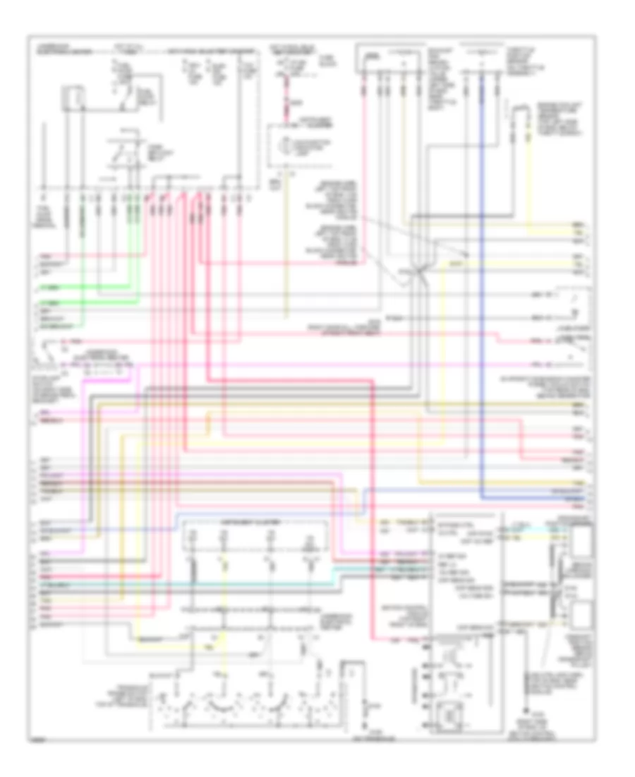
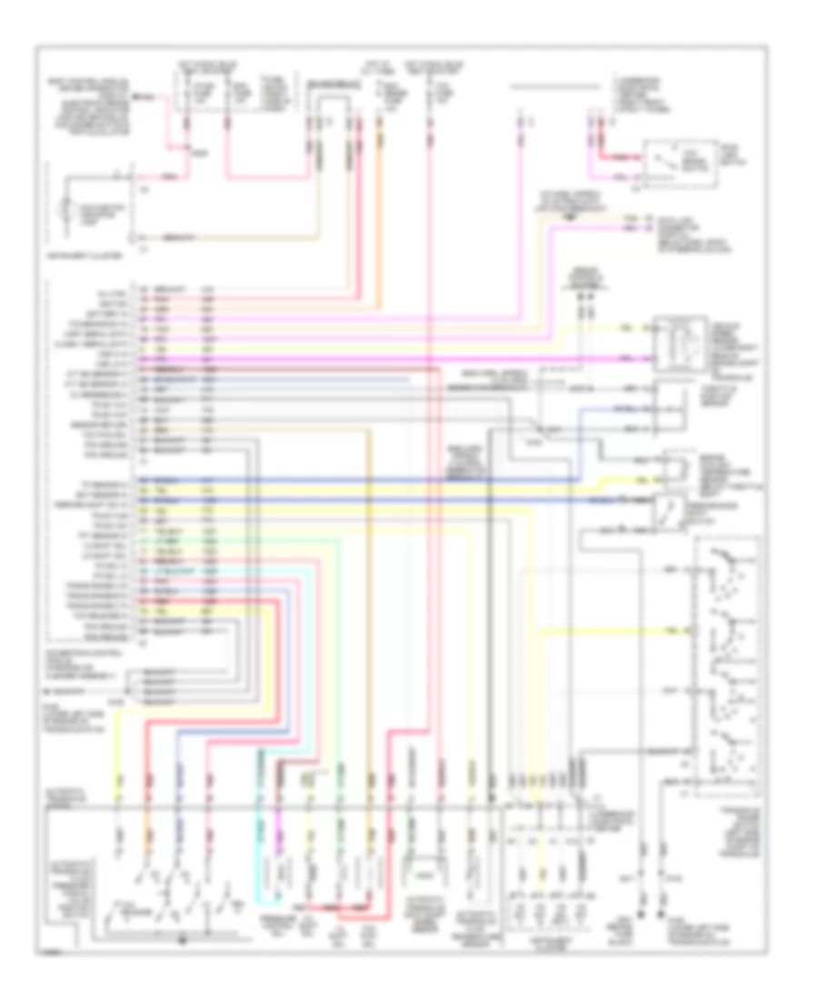
3.1L 3.1L (VIN M), Transmission Wiring Diagram, 4T60-E for Pontiac Grand Prix GTP 1997 List of elements for 3.1L (VIN M), Transmission Wiring Diagram, 4T60-E for Pontiac Grand Prix GTP 1997: 72 (3.1l only) (3.1l) (3.8l) (all) (eng harn, approx 10 cm from generator breakout) (fuel injector harn, approx 2 cm from no 3 fuel injector breakout-3.1l only) (i/p harn, approx 30 cm from data link conn breakout) s237 1-2 shift sol 2-3 shift sol 5v reference a A12 Automatic transaxle (4t60-e) Automatic transaxle fluid temperature sensor B10 Battery in Body control module, driver information display, electronic brake control lamp driver module & head-up display dimmer switch C10 Class ii serial data D10 D11 Data link connector (partial) (below dash, right of steering column) Ecm fuse 10a Ecm sense fuse 10a Ect sensor in Engine controls system Engine coolant temperature sensor (below throttle body) F12 underhood electrical center Fuse block G129 (lower left side of engine on transaxle stud) Hot at all times Hot in run, bulb test or start I/p ign fuse 10a Ign main relay Ignition Instrument cluster Malfunction indicator lamp Mil ctrl Pcm ground Pnk Powertrain control module (in engine air cleaner assembly) Red S105 S106 S107 S121 (3.1l) S122 (eng harn, approx 4 cm from generator breakout) S209 Sensor return Stop lamp switch Tan Tcc fuse 10a Tcc pwm sol Tcc sol Tcc/ brake switch Tcc/brake sw in Tft sensor in Throttle position sensor Tp sensor in Tr sw a Tr sw b Tr sw c Tr sw in-a Tr sw in-b Tr sw in-p Tr sw inc Tr sw prty Transaxle range switch (left side of engine compt on transaxle) Uart serial data Underhood electrical center Vehicle speed sensor (lower right rear of engine compt on transaxle) Vss hi in Vss lo in
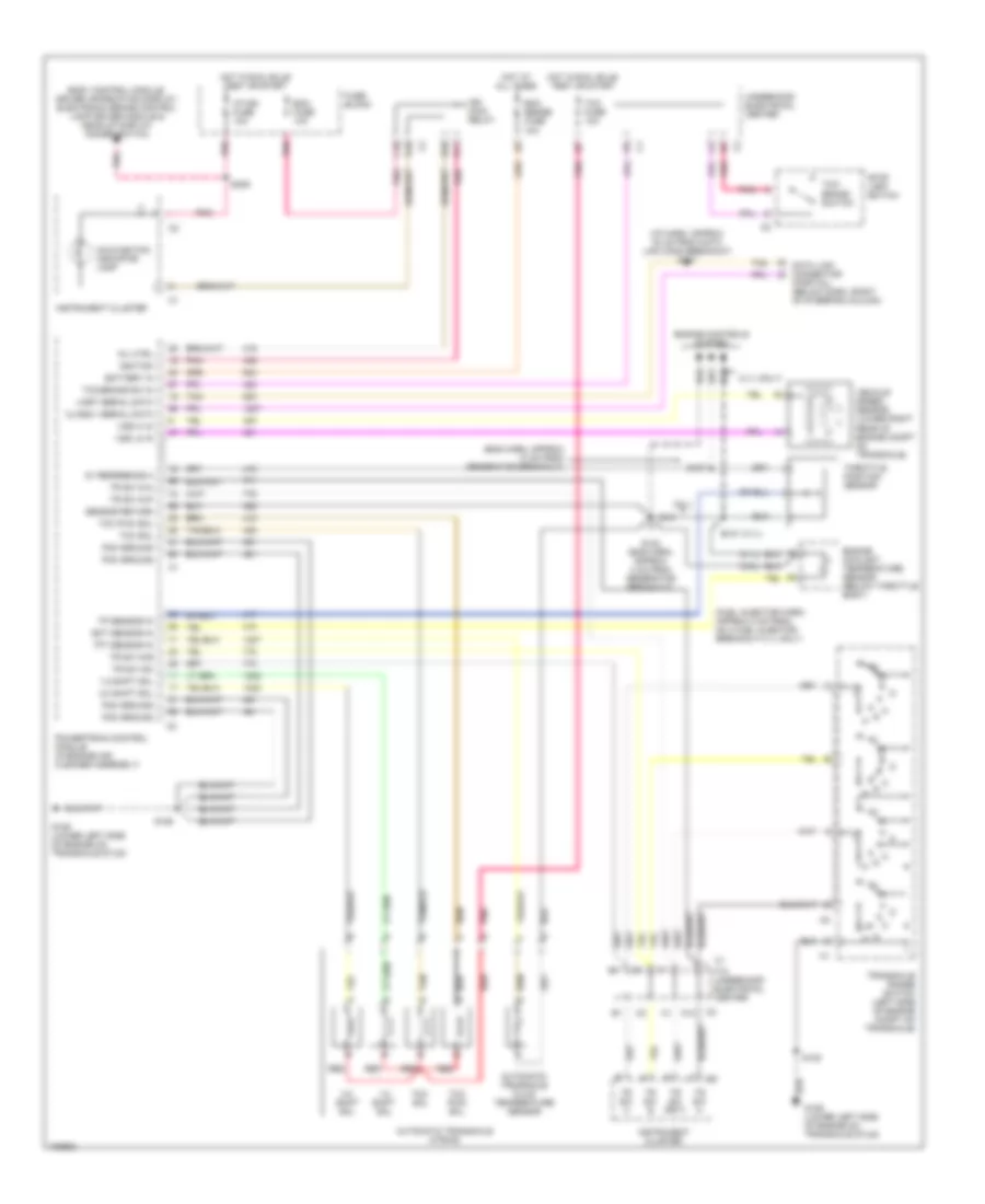
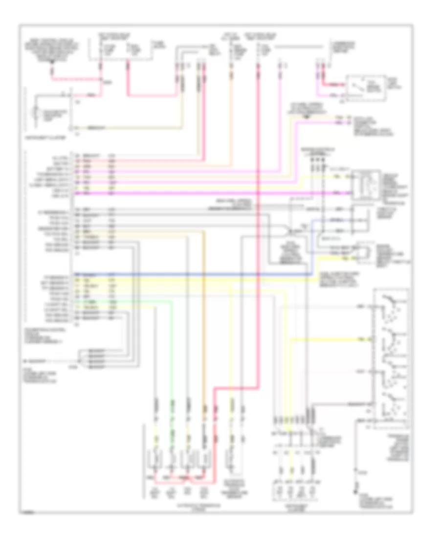
3.8L 3.8L (VIN 1), Transmission Wiring Diagram, 4T65-E for Pontiac Grand Prix GTP 1997 List of elements for 3.8L (VIN 1), Transmission Wiring Diagram, 4T65-E for Pontiac Grand Prix GTP 1997: 84 (eng harn, approx 10 cm from generator breakout) (eng harn, approx 4 cm from generator breakout) (i/p harn, approx 30 cm from data link conn breakout) s237 1-2 shift sol 2-3 shift sol 5v reference a A/t iss sensor hi A/t iss sensor lo A12 Automatic transaxle (4t65-e) Automatic transaxle fluid pressure manual valve position switch Automatic transaxle fluid temperature sensor Automatic transaxle input shaft speed sensor B10 Battery in Body control module, driver information display, electronic brake control indicator lamp driver module, hud dimmer switch & trip calculator C10 Class ii serial data D10 D11 Data link connector (partial) (below dash, right of steering column) Ecm fuse 10a Ecm sense fuse 10a Ect sensor in Engine controls system Engine coolant temperature sensor (below throttle body) F12 underhood electrical center Fuse block (right side of dash) G129 (lower left side of engine on transaxle stud) G201 (behind fuse block) Hot at all times Hot in run, bulb test or start I/p-ign fuse 10a Ign main relay Ignition Instrument cluster Malfunction indicator lamp Mil ctrl Nca Pc sol hi Pc sol lo Pcm ground Perform shift sw in Performance shift switch Pnk Powertrain control module (in engine air cleaner assembly) Pressure control sol Red Rev S105 S106 S107 S122 S209 S211 Sensor return Stop lamp switch Tan Tcc fuse 10a Tcc pwm sol Tcc release Tcc release in Tcc/ brake switch Tcc/brake sw in Tft sensor in Throttle position sensor Tp sensor in Tr sw a Tr sw b Tr sw c Tr sw in-a Tr sw in-b Tr sw in-p Tr sw inc Tr sw prty Trans range a in Trans range b in Trans range c in Transaxle range switch (left side of engine compt on transaxle) Uart serial data Underhood electrical center (right front strut tower) Vehicle speed sensor (lower right rear of engine compt on transaxle) Vss hi in Vss lo in 3.8L (VIN K), Transmission Wiring Diagram, 4T60-E for Pontiac Grand Prix GTP 1997 List of elements for 3.8L (VIN K), Transmission Wiring Diagram, 4T60-E for Pontiac Grand Prix GTP 1997: 72 (3.1l only) (3.1l) (3.8l) (all) (eng harn, approx 10 cm from generator breakout) (fuel injector harn, approx 2 cm from no 3 fuel injector breakout-3.1l only) (i/p harn, approx 30 cm from data link conn breakout) s237 1-2 shift sol 2-3 shift sol 5v reference a A12 Automatic transaxle (4t60-e) Automatic transaxle fluid temperature sensor B10 Battery in Body control module, driver information display, electronic brake control lamp driver module & head-up display dimmer switch C10 Class ii serial data D10 D11 Data link connector (partial) (below dash, right of steering column) Ecm fuse 10a Ecm sense fuse 10a Ect sensor in Engine controls system Engine coolant temperature sensor (below throttle body) F12 underhood electrical center Fuse block G129 (lower left side of engine on transaxle stud) Hot at all times Hot in run, bulb test or start I/p ign fuse 10a Ign main relay Ignition Instrument cluster Malfunction indicator lamp Mil ctrl Pcm ground Pnk Powertrain control module (in engine air cleaner assembly) Red S105 S106 S107 S121 (3.1l) S122 (eng harn, approx 4 cm from generator breakout) S209 Sensor return Stop lamp switch Tan Tcc fuse 10a Tcc pwm sol Tcc sol Tcc/ brake switch Tcc/brake sw in Tft sensor in Throttle position sensor Tp sensor in Tr sw a Tr sw b Tr sw c Tr sw in-a Tr sw in-b Tr sw in-p Tr sw inc Tr sw prty Transaxle range switch (left side of engine compt on transaxle) Uart serial data Underhood electrical center Vehicle speed sensor (lower right rear of engine compt on transaxle) Vss hi in Vss lo in
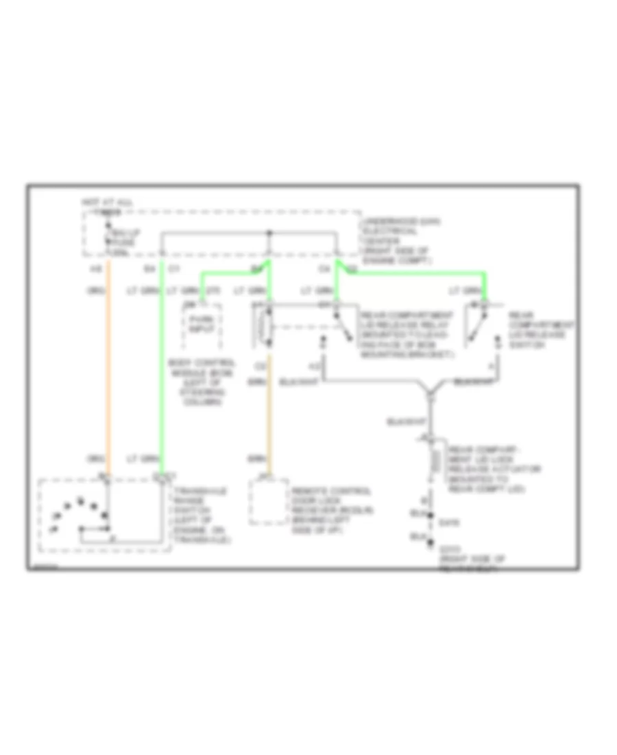
TRUNK, TAILGATE, FUEL DOOR Trunk Release Wiring Diagram for Pontiac Grand Prix GTP 1997 List of elements for Trunk Release Wiring Diagram for Pontiac Grand Prix GTP 1997: 13 B/u lp fuse 10a Body control module (bcm) (left of steering column) C1 c G313 (right side of rear shelf) Hot at all times Park input Rear compart- ment lid lock release actuator (mounted to rear compt lid) Rear compartment lid release relay (mounted to lead- ing face of bcm mounting bracket) Rear compartment lid release switch Remote control door lock reciever (rcdlr) (behind left side of i/p) S416 Transaxle range switch (left of engine, on transaxle) Underhood (u/h) electrical center (right side of engine compt)
WARNING SYSTEMS Warning System Wiring Diagrams for Pontiac Grand Prix GTP 1997 List of elements for Warning System Wiring Diagrams for Pontiac Grand Prix GTP 1997: 76 (base) (i/p harn, approx 3 cm from remote control door lock receiver breakout) s262 (i/p harn, approx 4 cm from from headlamp switch break- out) (i/p harn, approx 7 cm from driver's information display/trip calculator breakout) s289 (i/p harn, approx at the driver's information display/trip calculator breakout) s290 (not used) (up level) Accy1 Aux chime B10 Base Bat Body control module (bcm) (below left side of i/p, left of steering column) C12 C13 C14 C15 C201 Check tire pressure reset switch (below left side of i/p) Ck tire psi D12 Driver information display (did) Driver's door ajar input Driver's seat belt switch Electronic brake control module (ebcm) (below left side of i/p) Exterior lights system Fasten belts output Fasten belts warning ind Fuse block G201 (right side of i/p cross beam, behind fuse block) G309 (left front door sill) Ground Hazard lamp & turn signal lamp flasher (below left side of i/p) Head Head- lights system Headlamp switch Hot at all times Hot in accy or run Hot in run, bulb test or start I/p-ign fuse 10a Ign Ign 1 Ignition key alarm switch Ind ctrl Instru- ment cluster Instrument cluster system Int lamp fuse 10a Key in ign input Left front door lock (ajar indicator switch) Left turn input Lights off input Mall fuse 10a Mall pgm fuse 10a Nca Off Park Park lamp fuse 37 20a Pnk Powertrain control module (pcm) (left side of engine compt, in side air cleaner) Red Right turn input S209 S211 S226 (i/p harn, approx 11 cm from blower motor resistor/ control module breakout) S276 (i/p harn, approx 16 cm from remote control door lock receiver breakout) S282 S285 S303 S504 Seat belt switch input Tan Trip calculator Turn signal switch Underhood (u/h) electrical center Up level Vehicle speed input
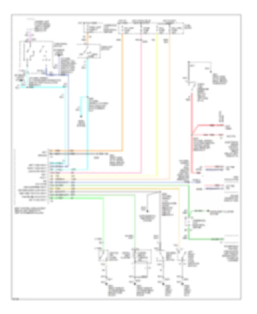
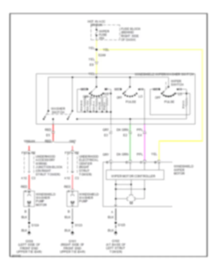
WIPER/WASHER Wiper/Washer Wiring Diagram for Pontiac Grand Prix GTP 1997 List of elements for Wiper/Washer Wiring Diagram for Pontiac Grand Prix GTP 1997: 26 1998-99 A12 F12 Fuse block (behind right side of dash) G101 (right side of front end upper tie bar) G102 (at base of left strut tower) G108 (left side of front end upper tie bar) Hot in acc or run Mist Off Pulse Red S123 S124 S125 S249 Underhood accessory wiring junction block (on right strut tower) Underhood electrical center (right strut tower) Washer switch Windshield washer pump Windshield washer pump motor Windshield wiper motor Windshield wiper/washer switch Wiper fuse 25a Wiper motor controller Wiper switch