AIR CONDITIONING
Compressor Wiring Diagram for Saturn Ion 2 2006

List of elements for Compressor Wiring Diagram for Saturn Ion 2 2006:
- (at rear of engine, near coolant overflow container) (2.0l) powertrain control module (pcm)
- (not used)
- +5v
- 2.0l
- 2.2l
- 2.4l
- A/c clutch relay
- A/c compressor clutch (at lower left front of engine)
- A/c diode
- A/c fuse 5 10a
- A/c on led
- A/c on/off
- A/c press
- A/c refrigerant pressure sensor (on lower left side of engine, below generator)
- A/c relay
- A/c request
- A/c switch
- A10
- Aa1
- Aa2
- Aa3
- Aa4
- B11
- Body control module (bcm) (at lower center of dash)
- Class 2 data
- Ect sens
- Engine control module (ecm) (2.2l & 2.4l) (at left side of engine compt)
- Engine coolant temperature (ect) sensor (2.0l: on top of engine, near right front corner of camshaft cover) (2.2l, 2.4l: on right rear side of engine, near exhaust manifold)
- F10
- G101 (behind left front headlamp)
- G203 (behind lower left side of dash, left of steering column)
- Hot at all times
- Hot in run or start
- Hvac control assembly
- Hvac fan switch
- Hvac fuse 7.5a
- Ign 3 volt
- Logic
- Low ref
- Off
- Red
- Run (ign 3) fuse 48 30a
- Run relay
- Run relay ctrl
- Run/ crank relay
- S101 (in forward lamp harness, near underhood fuse block connector)
- S233 (in i/p harness, approximately 20 cm from radio c1 breakout)
- Underhood fuse block (at left rear side of engine compartment)
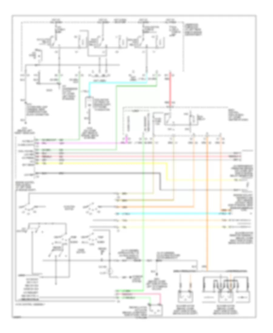
Manual A/C Wiring Diagram for Saturn Ion 2 2006
List of elements for Manual A/C Wiring Diagram for Saturn Ion 2 2006:
- (in i/p harness, 6.5 cm from blower motor breakout) s260
- (in i/p harness, approximately 20 cm from radio c1 breakout) s233
- (not used)
- +5v
- A/c clutch relay
- A/c compressor clutch (at lower left front of engine)
- A/c diode
- A/c fuse 5 10a
- A/c ind
- A/c press
- A/c refrigerant pressure sensor (on lower left side of engine, below generator)
- A/c relay
- A/c request
- A/c sig sw
- A/c switch
- A10
- Aa1
- Aa2
- Aa3
- Aa4
- B11
- Bi-lvl
- Blend
- Blower motor (behind lower right side of dash, behind glove compt)
- Blower motor resistor assembly (behind lower right side of dash, behind glove compt)
- Body control module (bcm) (at lower center of dash)
- Class 2 data
- Cool fan rel
- Cooling fan (at front of engine compt, attached to radiator)
- Cooling fan fuse 45 30a
- Cooling fan relay
- Def
- Early production
- Ect sens
- Engine control module (ecm) (at left side of engine compt)
- Engine coolant temperature (ect) sensor (on right rear side of engine, near exhaust manifold)
- F10
- G101 (behind left front headlamp)
- G105 (on lower left rear of engine, above starter)
- G203 (behind lower left side of dash, left of steering column)
- Hot at all times
- Hot in run or start
- Htr
- Hvac control assembly
- Hvac fan switch
- Hvac fuse 7.5a
- Ign 3 volt
- Illum
- Interior lights system
- Late production
- Logic
- Low ref
- Mode sw sig
- Mode switch
- Nca
- Off
- Rec dr ctrl a
- Rec dr ctrl b
- Rec sw sig
- Recirc ind
- Recirc switch
- Recirculation actuator (behind lower right side of dash, near "a" pillar)
- Red
- Run (ign 3) fuse 48 30a
- Run relay
- Run relay ctrl
- Run/ crank relay
- S101 (in forward lamp harness, near underhood fuse block connector)
- Tan
- Underhood fuse block (at left rear side of engine compartment)
- Vent
ANTI-LOCK BRAKES
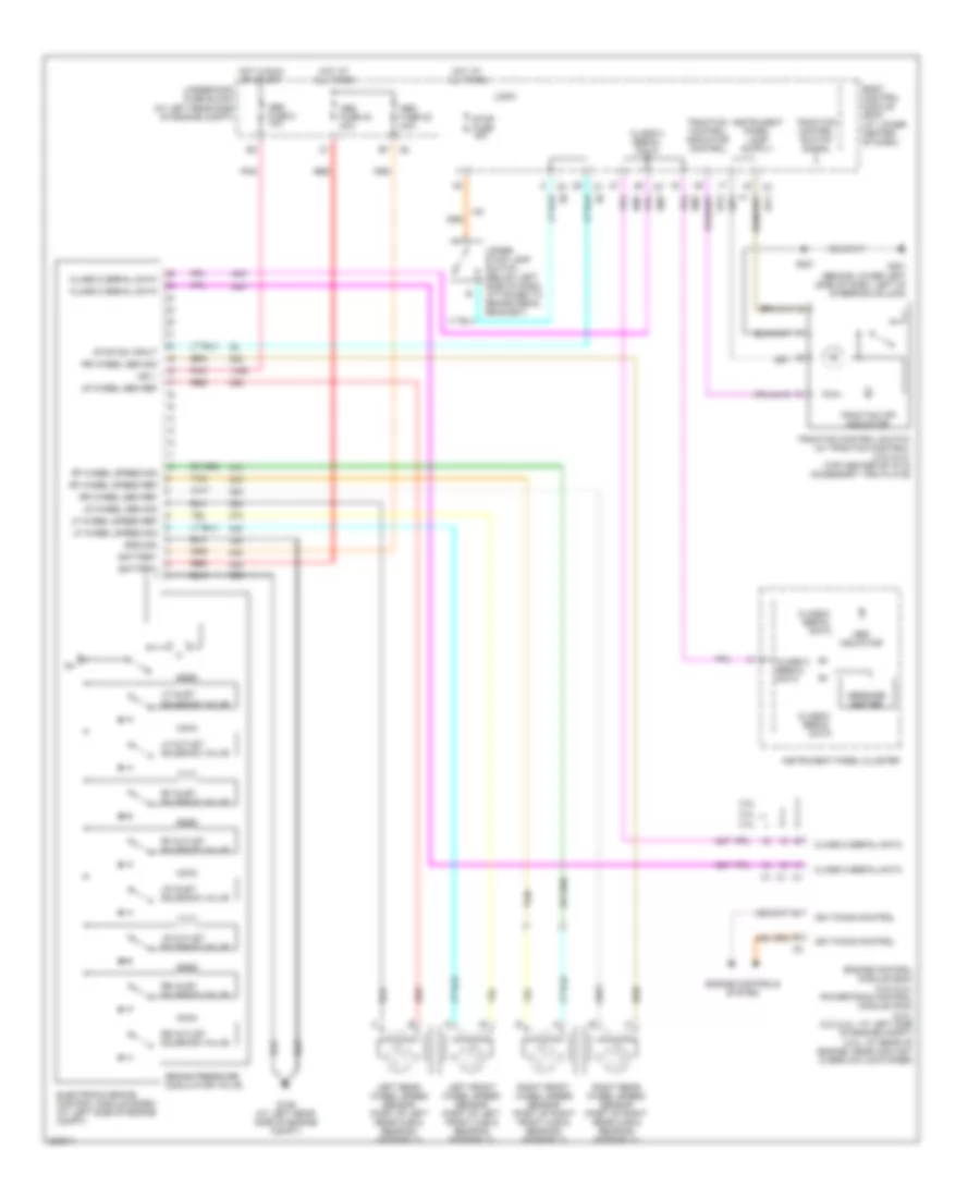
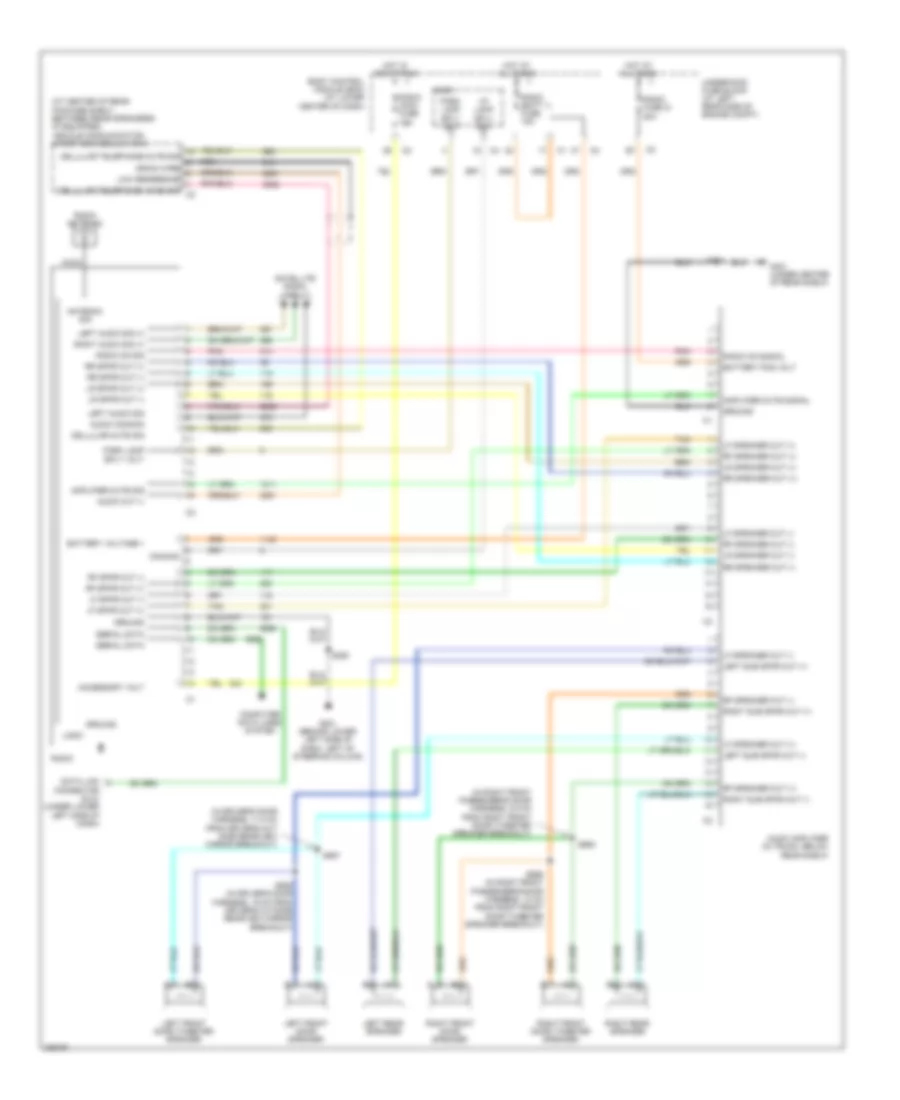
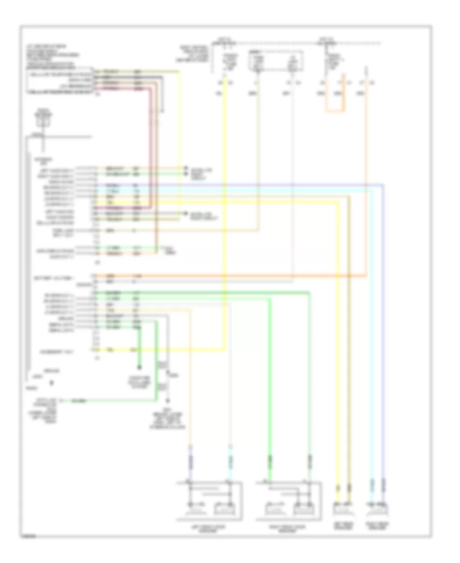
Anti-lock Brakes Wiring Diagram for Saturn Ion 2 2006
List of elements for Anti-lock Brakes Wiring Diagram for Saturn Ion 2 2006:
- 2.0l 2.4l
- 2.2l
- Abs fuse 22 20a
- Abs fuse 40 40a
- Abs fuse 8 10a
- Abs indicator
- Battery
- Body control module (bcm) (at lower center of dash)
- Brake pressure modulator valve
- Class 2 serial data
- Electronic brake control module (ecbm) (at left side of engine compt)
- Engine control module (ecm) (2.2l/2.4l) powertrain control module (pcm) (2.0l) (2.2l/2.4l: at left side of engine compt) (2.0l: at rear of engine, near coolant overflow container)
- Engine controls system
- G109 (at left rear side of engine compt)
- G201 (behind lower left side of dash, left of steering column)
- Ground
- Hot at all times
- Hot in run or start
- Ign 1
- Ign timing control
- Instrument panel cluster
- Left front wheel speed sensor (part of left front hub & bearing assembly)
- Left rear wheel speed sensor (part of left rear hub & bearing assembly)
- Lf inlet solenoid valve
- Lf outlet solenoid valve
- Lf wheel speed ref
- Lf wheel speed sig
- Logic
- Lr inlet solenoid valve
- Lr outlet solenoid valve
- Lr wheel sen ref
- Lr wheel sen sig
- Message center
- Pnk
- Red
- Rf inlet solenoid valve
- Rf outlet solenoid valve
- Rf wheel speed ref
- Rf wheel speed sig
- Right front wheel speed sensor (part of right front hub & bearing assembly)
- Right rear wheel speed sensor (part of right rear hub & bearing assembly)
- Rr inlet solenoid valve
- Rr outlet solenoid valve
- Rr wheel sen ref
- Rr wheel sen sig
- S221
- Stop fuse 15a
- Stop sw input
- Tan
- Traction control indicator control
- Traction control switch (w/ traction control) (2.2l/2.4l) (top center of i/p in accessory trim plate)
- Traction control switch signal
- Traction off indicator
- Underhood fuse block (at left rear side of engine compt)
- Upper stop lamp switch (below left side of dash, attached to brake pedal bracket)
ANTI-THEFT
Anti-theft Wiring Diagram for Saturn Ion 2 2006
List of elements for Anti-theft Wiring Diagram for Saturn Ion 2 2006:
- (2.0l: at rear of engine, near coolant overflow container) (2.2l & 2.4l: at left side of engine compt) (2.0l) powertrain control module (pcm) (2.2l & 2.4l) engine control module (ecm)
- (in body harness, 7.5 cm from rear compartment light breakout) s413
- (near front left passenger seat belt)
- 2.0l
- 2.2l
- 2.2l & 2.4l
- 2.4l
- 5v ref
- Acc
- Ajar switch
- B(+)
- Bcm (pwr) fuse 15a
- Bcm class 2 serial data
- Bcm elect fuse 20a
- Body control module (bcm) (at lower center of dash)
- Cluster/ aos fuse 7.5a
- Dash fuse 7.5a
- Driver door jamb switch (behind left i/p access panel)
- Driver door jamb switch signal
- Ecm class 2 serial data
- Engine controls system
- Exterior lights system
- Front passenger door jamb switch (right front of dash, on outer trim cover)
- Fuel injector control
- G201 (behind lower left side of dash, left of steering column)
- G301 (under driver's seat)
- G403 (under center of rear shelf)
- Gnd
- Horn relay ctrl
- Horns system
- Hot at all times
- Ignition switch
- Instrument panel cluster
- Interior lights system
- Left rear door jamb switch (sedan) (in right "b" pillar)
- Logic
- Nca
- Off
- Off/ run/ crank volt
- Passenger door jamb switch signal
- Rear compartment lid latch (in rear compartment lid)
- Right rear door jamb switch (sedan)
- Run
- S221
- S250
- S351
- S990
- Security indicator
- Security indicator control
- Start
- Trunk ajar switch signal
- Turn/ hazard switch power
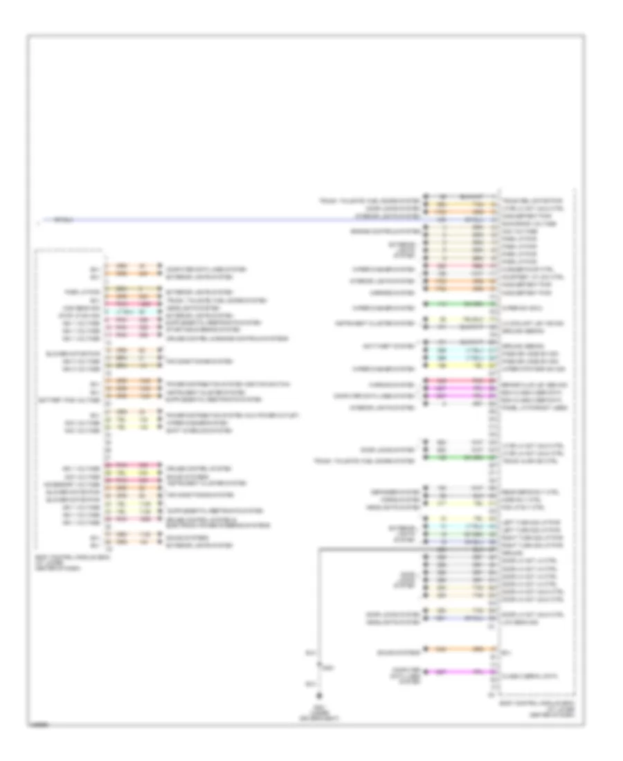
BODY CONTROL MODULES
Body Control Modules Wiring Diagram (1 of 2) for Saturn Ion 2 2006
List of elements for Body Control Modules Wiring Diagram (1 of 2) for Saturn Ion 2 2006:
- (sedan) mirrors system (coupe) power tops & mirrors systems
- 5v ref
- A/c request sig
- A10
- Acc pwr
- Acc voltage
- Air conditioning system
- Anti-lock brakes system
- Anti-theft system
- B (+)
- B(+)
- B11
- Bcm class 2 ser data
- Body control module (bcm) (at lower center of dash)
- Computer data lines system
- Defogger system
- Drl amb light sen ref
- Drl amb light sen sig
- Drv dr jamb sw sig
- Engine controls system
- Exterior lights system
- Fog lp rly ctrl
- Fog lp sw sig
- Fuel pump pwr
- Fuel pump rly ctrl
- G101 (behind left front headlamp)
- G201 (behind lower left side of dash, left of steering column)
- Ground
- Headlamps off sig
- Headlights system
- High beam sig
- Horn rly ctrl
- Horns system
- Hot at all times
- Ign 1 pwr
- Ign 3 pwr
- Interior lights system
- Ip batt 1 fuse 39 30a
- Ip batt 1a fuse 47 30a
- Ip batt 2 fuse 41 40a
- Low beam pwr
- Low beam sig
- Low ref
- Lp dim ctrl
- Lt turn sig pwr
- Off/run/crank pwr
- Panel lp pwr
- Park brake sw sig
- Park lp pwr
- Pass dr jamb sw sig
- Pass seat belt ind
- Pnk
- Power distribution system
- Power distribution system (ignition switch)
- Power windows system
- Pwr window sw lockout ctrl (sedan)
- Rear defog rly ctrl
- Rear defog sw sig
- Red
- Rt turn sig pwr
- Run (ign 3) fuse 48 30a
- Run/ crank fuse 38 30a
- Run/ crank relay
- Run/crank pwr
- S101
- S250
- Security ind ctrl
- Shift interlock system
- Shift lk sol pwr
- Sound systems
- Stop lp sw sig
- Trac ctrl ind
- Trac ctrl sw sig
- Turn/haz sw pwr
- Underhood fuse block (at left rear side of engine compt)
- Warning system
- Washer pump ctrl
- Wiper sw sig 1
- Wiper/washer system
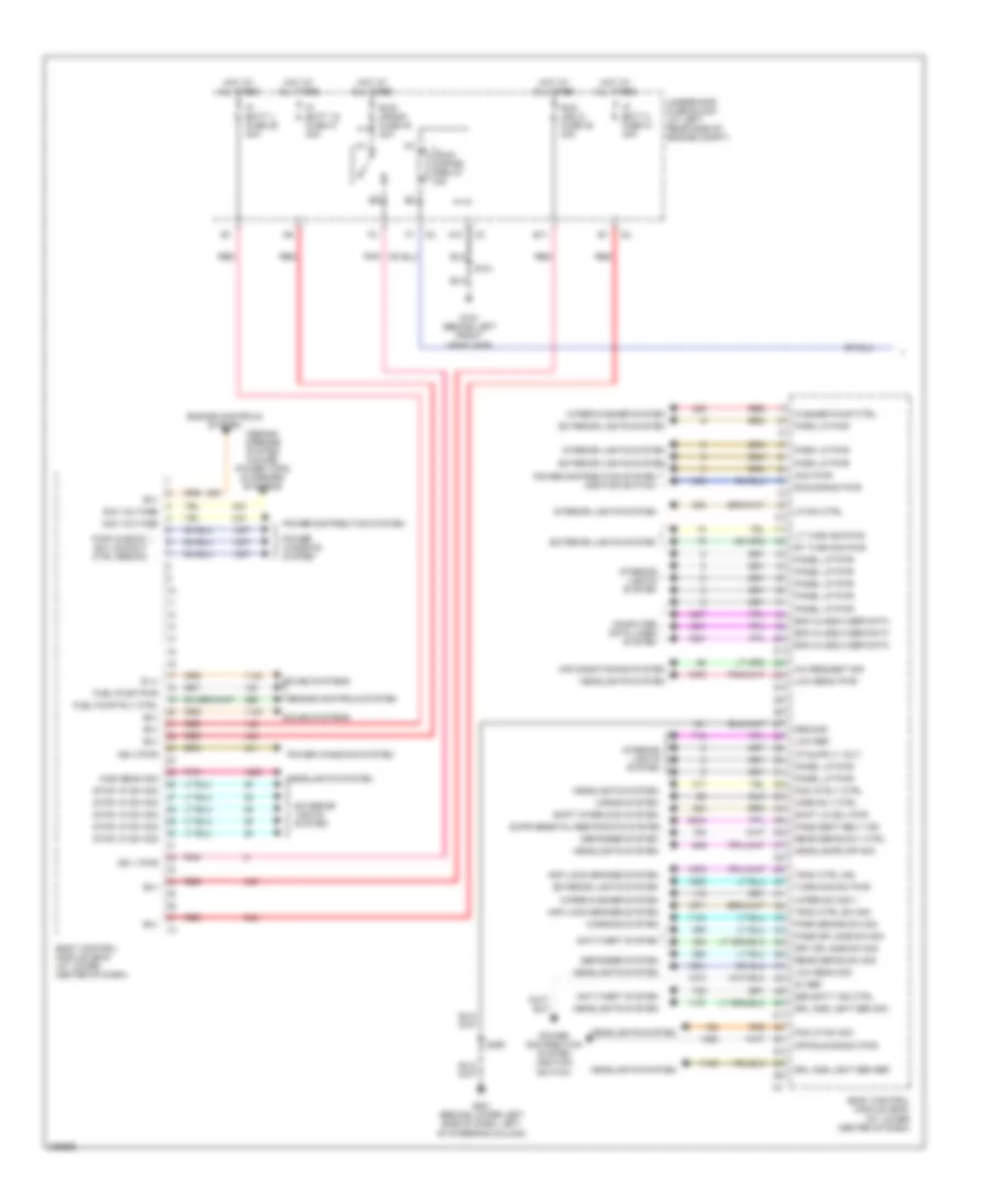
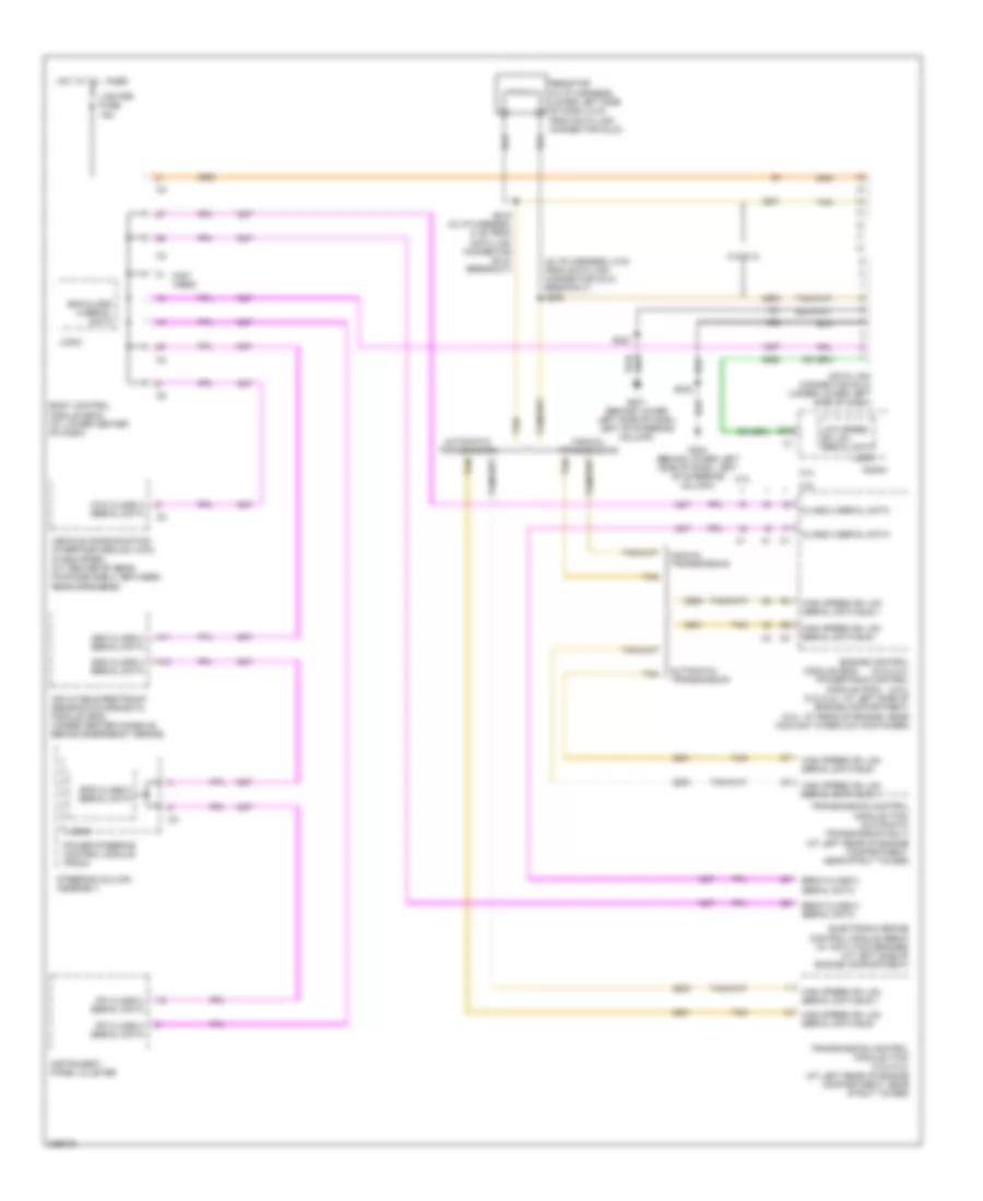
Body Control Modules Wiring Diagram (2 of 2) for Saturn Ion 2 2006
List of elements for Body Control Modules Wiring Diagram (2 of 2) for Saturn Ion 2 2006:
- Acc voltage
- Accessory voltage
- Air conditioning system
- Anti-theft system
- B(+)
- Battery pos voltage
- Bcm class 2 ser data
- Blower motor pwr
- Body control module (bcm) (at lower center of dash)
- Brake fluid lev sen sig
- Class 2 serial data
- Computer data lines system
- Courtesy lp low ctrl
- Cruise control & engine controls systems
- Cruise control system
- Cruise control system & electronic power steering systems
- Defogger system
- Door lk act lk ctrl
- Door lk act unlk ctrl
- Door locks system
- Engine controls system
- Exterior lights system
- Fog lp rly ctrl
- G301 (under driver's seat)
- Ground
- Ground (sedan)
- Headlights system
- High beam sig
- Horn rly ctrl
- Horns system
- Ign 1 voltage
- Ign 3 voltage
- Inadvertent pwr
- Instrument cluster system
- Interior lights system
- Left turn sig lp pwr
- Lf dr lk act unlk ctrl
- Lo coolant lev ind sig
- Low beam sig
- Mirrors system
- Panel lp pwr(not used)
- Park lp pwr
- Pass dr jamb sw sig
- Pnk
- Power distribution system (aux power outlet)
- Power distribution system (ignition switch)
- Rear defog rly ctrl
- Red
- Right turn sig lp pwr
- Run/crank voltage
- S351
- Shift interlock system
- Sound systems
- Starting/charging system
- Stop lp sw sig
- Tan
- Trunk ajar ind ctrl
- Trunk rel motor pwr
- Trunk, tailgate, fuel doors system
- Warning system
- Washer pump ctrl
- Wiper mtr park sw sig
- Wiper sw sig 2
- Wiper/washer system
COMPUTER DATA LINES
Computer Data Lines Wiring Diagram for Saturn Ion 2 2006
List of elements for Computer Data Lines Wiring Diagram for Saturn Ion 2 2006:
- (in i/p harness, 5 cm from data link connector (dlc) breakout) s205
- (not used)
- 2.0l
- 2.2l
- 2.2l/2.4l
- 2.4l
- A11
- A12
- Automatic transmission
- B10
- Bcm class 2 serial data
- Body control module (bcm) (at lower center of dash)
- Class 2 serial data
- Data link connector (dlc) (under lower left side of dash)
- Ebcm class 2 serial data
- Electronic brake control module (ebcm) (w/ anti-lock brakes) (at left side of engine compartment)
- Engine control (2.2l/2.4l) powertrain control (2.0l) (2.2l/2.4l: at left side of engine compartment) (2.0l: at rear of engine, near coolant overflow container)
- Eps class 2 serial data
- G201 (behind lower left side of dash, left of steering column)
- G203 (behind lower left side of dash, left of steering column)
- High speed gm lan serial data bus +
- High speed gm lan serial data bus -
- Hot at all times
- Inflatable restraint sensing & diagnostic module (sdm) (under center console, behind emergency brake)
- Instrument panel cluster
- Ipc class 2 serial data
- Lighter fuse 15a
- Logic
- Low speed gm lan serial data
- Manual transmission
- Module (ecm)
- Module (pcm)
- Power steering control module (pscm)
- Radio
- Resistor (in i/p harness, lower left side of dash, 6 cm from data link connector (dlc))
- S215 (in i/p harness, 6 cm from data link connector (dlc) breakout)
- S221
- S233
- Sdm class 2 serial data
- Steering column assembly
- Tan
- Transmission control module (tcm) (2.2l/2.4l) (at left rear of engine compartment, near strut tower)
- Transmission control module (tcm) (automatic transmission only) (at left rear of engine compartment, near strut tower)
- Vcim class 2 serial data
- Vehicle communication interface module (vcim) (if equipped) (at center of rear package shelf, between rear speakers)
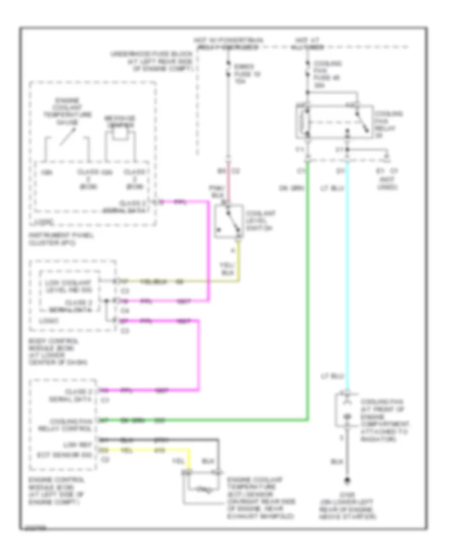
COOLING FAN
2.2L VIN F
2.2L VIN F, Cooling Fan Wiring Diagram for Saturn Ion 2 2006
List of elements for 2.2L VIN F, Cooling Fan Wiring Diagram for Saturn Ion 2 2006:
- (not used)
- B6 c2
- Body control module (bcm) (at lower center of dash)
- Class (bcm)
- Class 2 serial data
- Coolant level switch
- Cooling fan (at front of engine compartment, attached to radiator)
- Cooling fan fuse 45 30a
- Cooling fan relay
- Cooling fan relay control
- E1 c1
- Ect sensor sig
- Emiss fuse 10 15a
- Engine control module (ecm) (at left side of engine compt)
- Engine coolant temperature (ect) sensor (on right rear side of engine, near exhaust manifold)
- Engine coolant temperature gauge
- G105 (on lower left rear of engine, above starter)
- Hot at all times
- Hot w/ powertrain relay energized
- Ign
- Instrument panel cluster (ipc)
- Logic
- Low coolant level ind sig
- Low ref
- Message center
- Underhood fuse block (at left rear side of engine compt)
CRUISE CONTROL
Cruise Control Wiring Diagram for Saturn Ion 2 2006
List of elements for Cruise Control Wiring Diagram for Saturn Ion 2 2006:
- (behind steering wheel) inflatable restraint steering wheel module coil
- 2.0l
- 2.0l
- 2.0l/2.2l
- 2.2l
- 2.2l/2.4l
- 2.4l
- 5 volt ref 1
- 5 volt ref 2
- 5v ref 1
- 5v ref 2
- Accelerator pedal position (app) sensor (below left side of dash)
- All times
- App sens 1 sig
- App sens 2 sig
- Body control module (bcm) (at lower center of dash)
- Class 2 ecm
- Clutch pedal position (cpp) switch (m/t) (below left side of dash)
- Clutch/ brake/aos fuse 7.5a
- Cpp sw sig
- Cruise control on ind
- E10
- Ecm class 2 serial data
- Engine control module (ecm) (2.2l/2.4l) powertrain control module (pcm) (2.0l) (2.2l/2.4l: at left side of engine compt) (2.0l: at rear of engine, near coolant overflow container)
- Eps/ cruise fuse 2a
- G203 (behind lower left side of dash, left of steering column)
- Hot at
- Hot in acc or run
- Instrument panel cluster (ipc)
- Ipc class 2 serial data
- Left steering wheel controls
- Logic
- Low ref
- Lower stop lamp switch (below left side of dash, attached to brake pedal bracket)
- Message center
- Pnk
- Resume/ accel
- Right steering wheel controls
- S227
- S233
- Set/ coast
- Set/coast resume/ accelerate signal
- Stop fuse 15a
- Stop lamp sw sig
- Tac mtr ctrl 1
- Tac mtr ctrl 2
- Tan
- Tcc brake sw/cruise
- Throttle body (2.0l: top left side of engine, below supercharger) (2.2l: top left side of engine)
- Tp sens 1 sig
- Tp sens 2 sig
- Transmission control module (tcm) (a/t: at left rear of engine compt, near strut tower)
- Underhood fuse block (at left rear side of engine compt)
- Upper stop lamp switch (below left side of dash, attached to brake pedal bracket)
- Vehicle speed sensor (vss) (m/t) (m/t: at rear of engine, on transaxle)
- Vss high
- Vss low
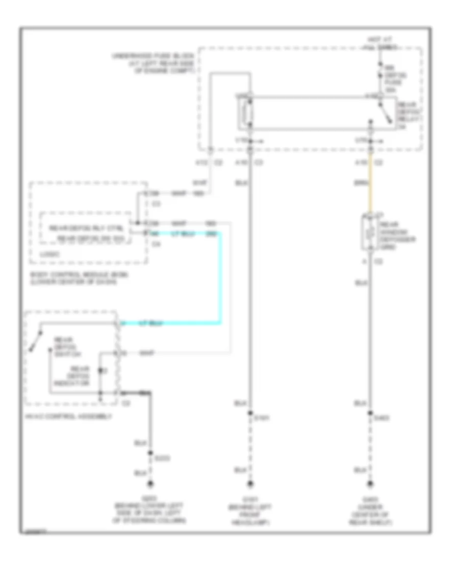
DEFOGGERS
Defoggers Wiring Diagram for Saturn Ion 2 2006
List of elements for Defoggers Wiring Diagram for Saturn Ion 2 2006:
- Body control module (bcm) (lower center of dash)
- C2 a
- C2 a10
- C2 a12
- C3 a10
- G101 (behind left front headlamp)
- G203 (behind lower left side of dash, left of steering column)
- G403 (under center of rear shelf)
- Hot at all times
- Hvac control assembly
- Logic
- Rear defog indicator
- Rear defog relay
- Rear defog rly ctrl
- Rear defog sw sig
- Rear defog switch
- Rear window defogger grid
- Rr defog fuse 30a
- S101
- S233
- S403
- U10
- U12
- Underhood fuse block (at left rear side of engine compt)
- V10
- V12
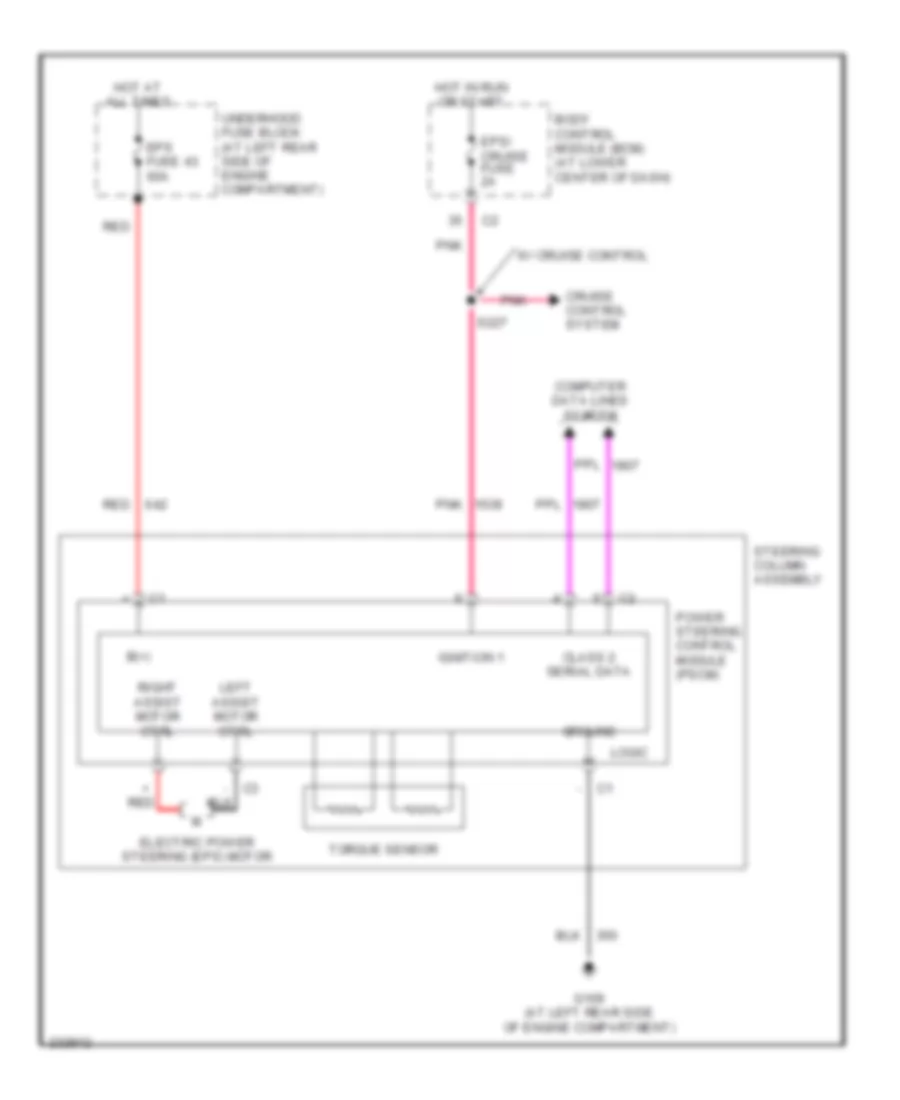
ELECTRONIC POWER STEERING
Electronic Power Steering Wiring Diagram for Saturn Ion 2 2006
List of elements for Electronic Power Steering Wiring Diagram for Saturn Ion 2 2006:
- + red
- - c3
- B(+)
- Body control module (bcm) (at lower center of dash)
- Class 2 serial data
- Computer data lines system
- Cruise control system
- Electric power steering (eps) motor
- Eps fuse 43 60a
- Eps/ cruise fuse 2a
- G109 (at left rear side of engine compartment)
- Ground
- Hot at all times
- Hot in run or start
- Ignition 1
- Left assist motor ctrl
- Logic
- Pnk
- Power steering control module (pscm)
- Red
- Right assist motor ctrl
- S227
- Steering column assembly
- Torque sensor
- Underhood fuse block (at left rear side of engine compartment)
- W/ cruise control
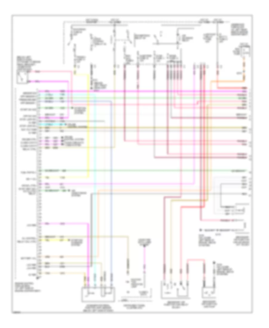
ENGINE PERFORMANCE
2.2L VIN F
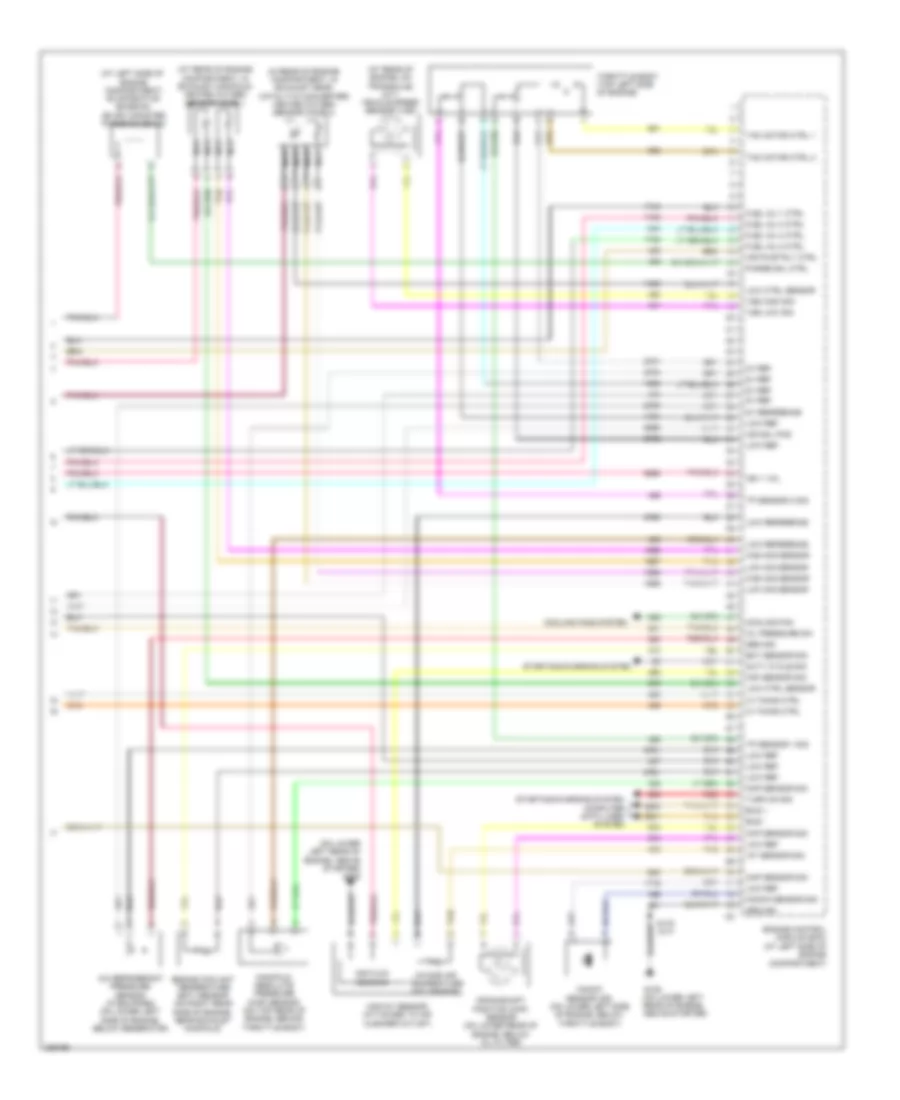
2.2L VIN F, Engine Performance Wiring Diagram (1 of 3) for Saturn Ion 2 2006
List of elements for 2.2L VIN F, Engine Performance Wiring Diagram (1 of 3) for Saturn Ion 2 2006:
- (air) solenoid (a/t, sulev)
- (behind left front headlamp) g101
- (below left side of dash, attached to brake pedal bracket) lower stop lamp switch
- 10a
- 5v ref
- A10
- Acc voltage
- Accelerator pedal position (app) sensor (below left side of dash)
- Air conditioning system
- Air pump relay fuse 40a
- Air sol ctrl
- Air solenoid relay
- App sensor 1
- App sensor 2
- B11
- Battery vol
- Class 2 data
- Computer data lines system
- Cpp sw sig
- Cruise control system
- Cruise ctrl
- E11
- Ecm inline fuse
- Ecm/
- Emiss fuse 10 15a
- Engine control module (ecm) (at left side of engine compartment)
- Etc fuse 9 15a
- Evap vent sol a/c clutch relay
- Fuel pmp rly
- G105 (on lower left rear of engine, above starter)
- Hot at all times
- Hot in run or start
- Id-ign fuse 11 10a
- Ign 1 vol
- Injectors fuse 16 10a
- Instrument panel cluster (ipc)
- Ip batt 2 fuse 41 40a
- Logic
- Low ref
- Malfunc- tion indicator lamp
- Mil control
- Nca
- Pnk
- Powertrain relay 29
- Pressure sen
- Red
- Relay coil ctrl
- Relay ctrl
- Run/ crank relay 28
- Run/crank fuse 38 30a
- S101
- S175
- S310
- Secondary air injection
- Secondary air injection (air) pump
- Secondary air injection (air) relay (sulev)
- Sensor sig
- Start sw sig
- Starting/ charging system
- Stop lamp sw
- Tan
- Trans 2 fuse 13 10a
- Underhood fuse block (at left rear side of engine compartment)
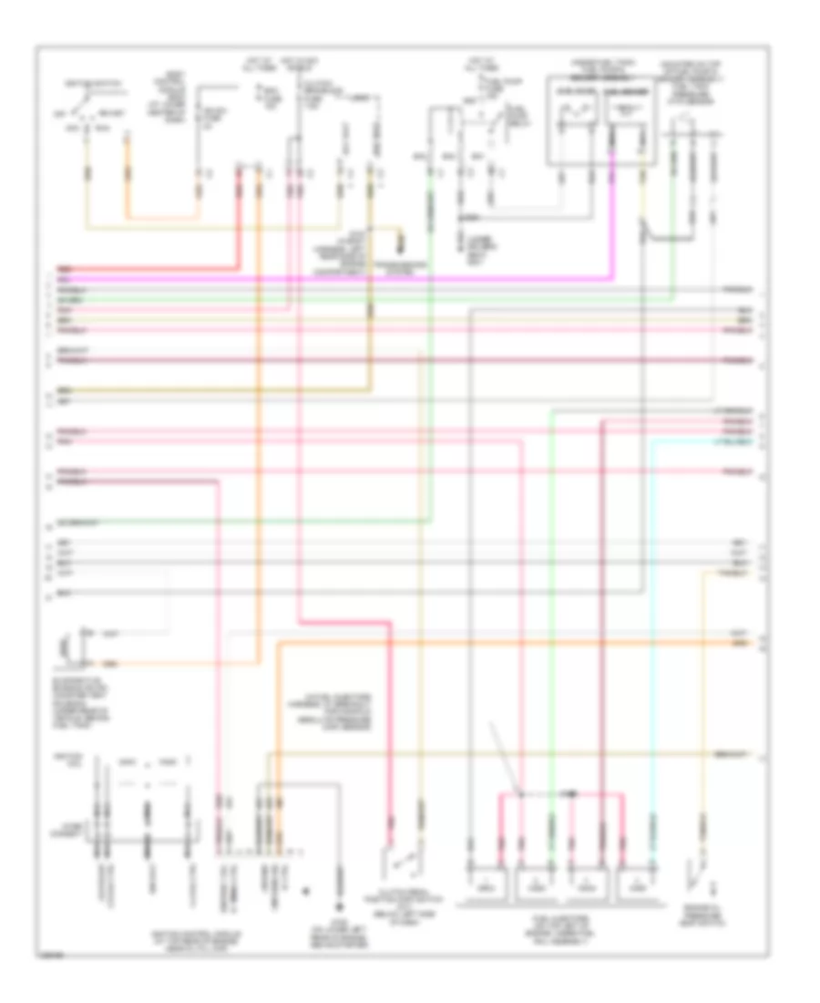
2.2L VIN F, Engine Performance Wiring Diagram (2 of 3) for Saturn Ion 2 2006
List of elements for 2.2L VIN F, Engine Performance Wiring Diagram (2 of 3) for Saturn Ion 2 2006:
- (in fuel injectors harness, at breakout for manifold absolute pressure (map) sensor)
- (inside fuel tank) fuel pump & sender assembly
- (mounted on top of fuel pump & sender assembly) fuel tank pressure (ftp) sensor
- (under driver's seat) g301
- 1-4 coil ctrl
- Acc
- Acc volt
- Ba1
- Ba2
- Ba3
- Ba4
- Bcm fuse 15a
- Body control module (bcm) (at lower center of dash)
- Clutch pedal position (cpp) switch (m/t) (below left side of dash)
- Clutch/ brake/aos fuse 7.5a
- Cmp send sig
- Csi pickup
- Engine oil pressure (eop) switch
- Evaporative emission (evap) canister vent solenoid (under rear of vehicle, behind fuel tank)
- Fuel injectors (on top left of engine, under fuel rail assembly)
- Fuel pump
- Fuel pump fuse 15a
- Fuel pump relay
- Fuel sender
- G105 (on lower left rear of engine, above starter)
- Ground
- Hot at all times
- Hot in acc or run
- Ic ctrl
- Ic timing ctrl
- Ign sw fuse 2a
- Ign volt
- Ignition 1 vol
- Ignition coil
- Ignition control module (at top rear of engine, near oil fill cap)
- Ignition switch
- Inter connect
- Logic
- Nca
- Nca 2-3 coil ctrl
- Off
- Pnk
- Red
- Run
- S104 (in body harness, left rear side of engine compartment)
- S139
- S351
- Start
- Tan
- Transmissions system
2.2L VIN F, Engine Performance Wiring Diagram (3 of 3) for Saturn Ion 2 2006
List of elements for 2.2L VIN F, Engine Performance Wiring Diagram (3 of 3) for Saturn Ion 2 2006:
- (at left side of engine compartment) evaporative emission (evap) canister purge solenoid
- (at left side of engine compartment)
- (at rear of engine compartment, in exhaust manifold) heated oxygen sensor (ho2s) 1
- (at rear of engine, on transaxle) (m/t) vehicle speed sensor (vss)
- (in rear of engine compartment, in exhaust near catalytic converter) heated oxygen sensor (ho2s) 2
- (on lower left rear of engine, above starter)
- (on lower left rear of engine, above starter) g105
- 5v ref
- 5v reference
- A/c refrigerant pressure sensor (if equipped) (on lower left side of engine, below generator)
- Air flow sensing
- Air pump rly ctrl
- Air sol pos
- Bus +
- Bus -
- Ckp sensor sig
- Cmp sensor sig
- Computer data lines system
- Cooling fan
- Cooling fans system
- Crankshaft position (ckp) sensor (on lower rear of engine, below oil filter)
- Duty cycle sig
- Ect sensor sig
- Engine control module (ecm)
- Engine coolant temperature (ect) sensor (on right rear side of engine, near exhaust manifold)
- Fuel inj 1 ctrl
- Fuel inj 2 ctrl
- Fuel inj 3 ctrl
- Fuel inj 4 ctrl
- G105
- Ground
- High sig sensor
- Iat sensor sig
- Ic timing ctrl
- Ign 1 vol
- Intake air temperature (iat) sensor
- Knock sensor (ks) (on lower left side of engine, below throttle body)
- Knock sensor sig
- Low ctrl sensor
- Low ref
- Low reference
- Low sig sensor
- Maf sensor sig
- Maf/iat sensor (attached to air cleaner outlet)
- Manifold absolute pressure (map) sensor (on top rear of engine, behind throttle body)
- Map sensor sig
- Nca
- Oil pressure sw
- Purge sol ctrl
- Red
- S175 (a/t)
- Sen sig
- Starting/charging system
- Tac motor ctrl 1
- Tac motor ctrl 2
- Tan
- Throttle body (top left side of engine)
- Tp sensor 1 sig
- Tp sensor 2 sig
- Turn on sig
- Vss high sig
- Vss low sig
EXTERIOR LIGHTS
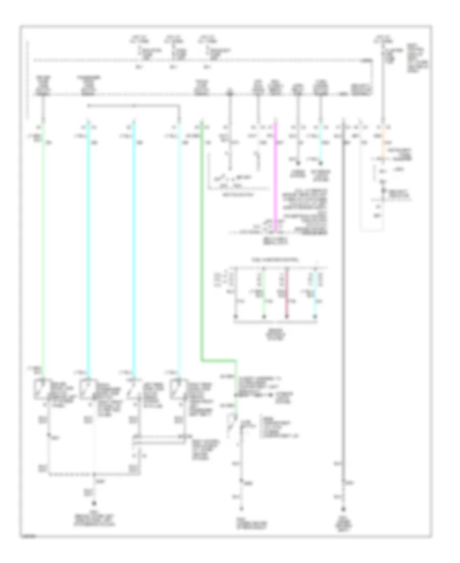
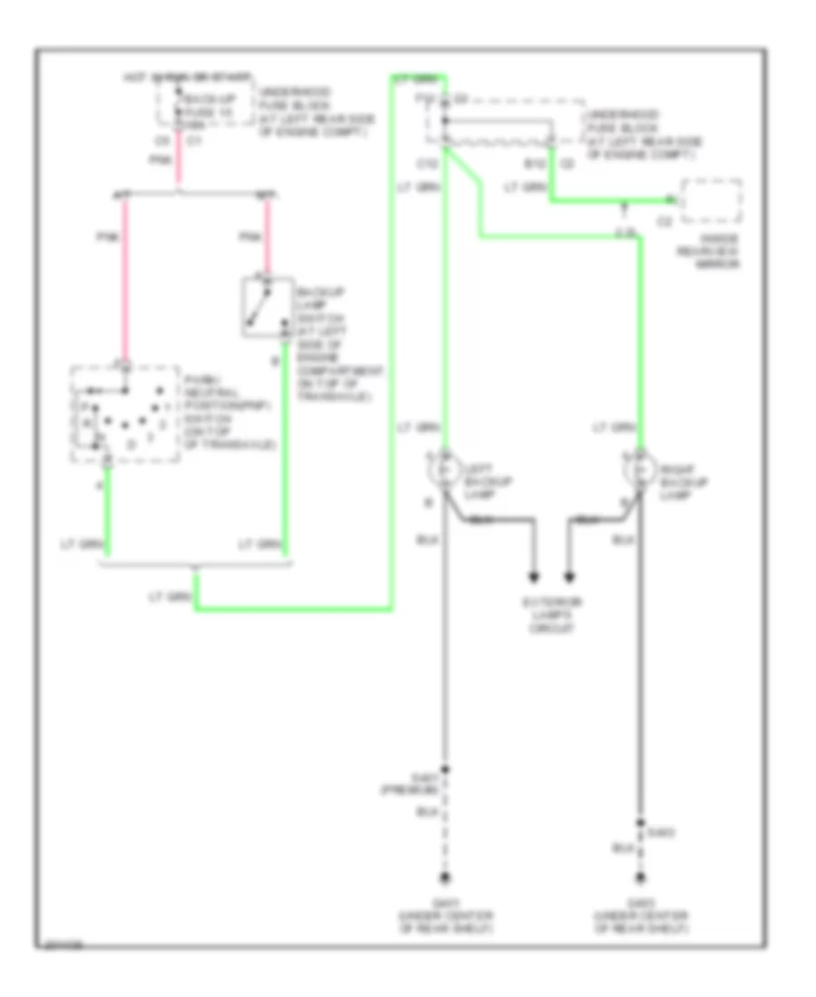
Back-up Lamps Wiring Diagram for Saturn Ion 2 2006
List of elements for Back-up Lamps Wiring Diagram for Saturn Ion 2 2006:
- 2.2l
- A/t
- Back-up fuse 15 10a
- Backup lamp switch (at left side of engine compartment, on top of transaxle)
- C12
- C2 b12
- Exterior lamps circuit
- F11
- G401 (under center of rear shelf)
- G403 (under center of rear shelf)
- Hot in run or start
- Inside rearview mirror
- Left backup lamp
- M/t
- Park/ neutral position(pnp) switch (on top of transaxle)
- Pnk
- Right backup lamp
- S401 (premium)
- S403
- Underhood fuse block (at left rear side of engine compt)
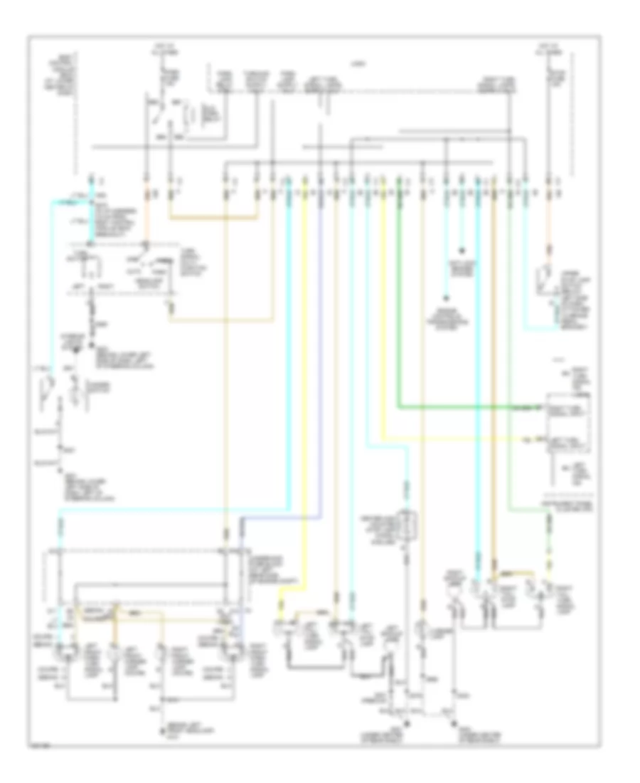
Exterior Lamps Wiring Diagram for Saturn Ion 2 2006
List of elements for Exterior Lamps Wiring Diagram for Saturn Ion 2 2006:
- (behind left front headlamp) g101
- (coupe)
- (coupe) (sedan) b
- (sedan)
- (sedan) a
- (sedan) g
- Alc/ park relay
- Anti-lock brakes system
- Auto
- B2 c2
- Bb1
- Bb2
- Bb3
- Bb4
- Body control module (bcm) (at lower center of dash)
- C2 f12
- C3 a12
- Center high mounted stop lamp (chmsl) (6 bulbs)
- D11
- D2 (not used)
- E12
- Engine controls/ transmissions system
- G201 (behind lower left side of dash, left of steering column)
- G203 (behind lower left side of dash, left of steering column)
- G401 (under center of rear shelf)
- G403 (under center of rear shelf)
- Hazard switch
- Head
- Headlamp switch
- Hot at all times
- Instrument panel cluster (ipc)
- Interior lights system
- Left
- Left backup lamp
- Left front marker lamp (coupe)
- Left front park/ turn signal lamp
- Left tail/ stop lamp
- Left tail/ turn signal lamp
- Left turn signal ind
- Left turn signal input
- License lamp
- Logic
- Off
- Park
- Park fuse 15a
- Park lamp relay ctrl
- Right
- Right backup lamp
- Right front marker lamp (coupe)
- Right front park/ turn signal lamp
- Right tail/ stop lamp
- Right tail/ turn signal lamp
- Right turn signal ind
- Right turn signal input
- S101
- S221
- S260
- S270 (in i/p harness, 5.5 cm from body control module (bcm) breakout)
- S375
- S401 (premium)
- S403
- S990
- Stop fuse 15a
- Turn signal/ multi- function switch
- Turn switch
- Underhood fuse block (at left rear side of engine compt)
- Upper stop lamp switch (below left side of dash, attached to brake pedal bracket)
GROUND DISTRIBUTION
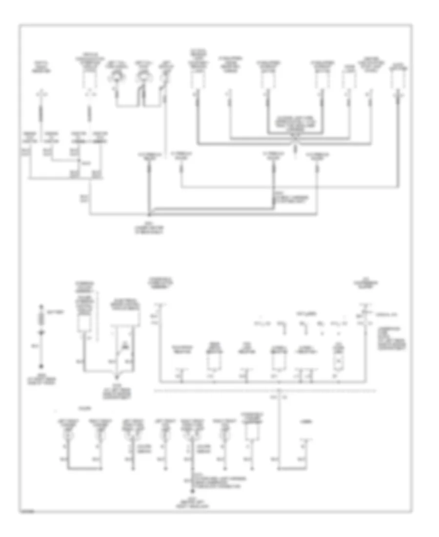
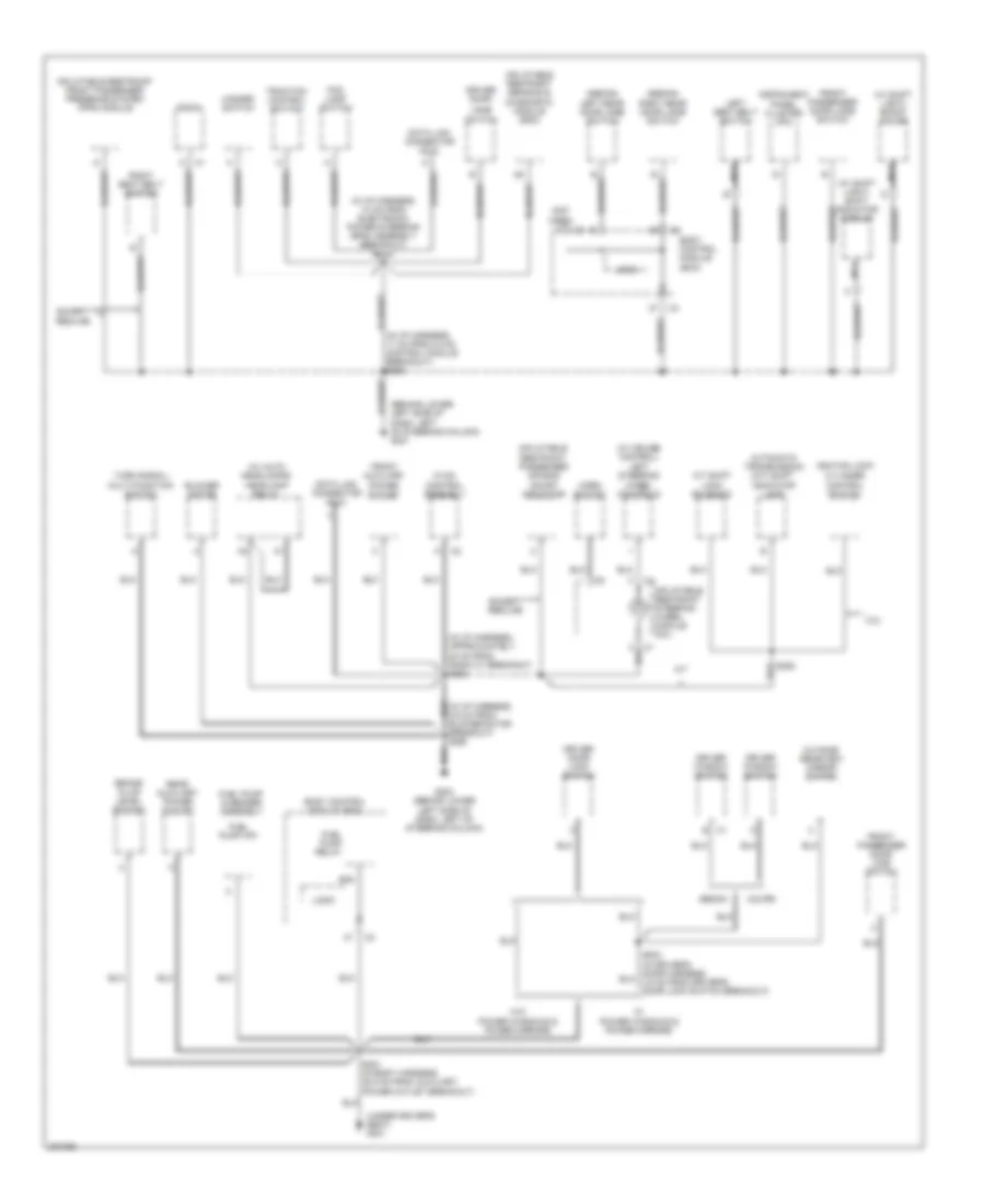
Ground Distribution Wiring Diagram (1 of 3) for Saturn Ion 2 2006
List of elements for Ground Distribution Wiring Diagram (1 of 3) for Saturn Ion 2 2006:
- (coupe)
- (if equipped) inside rearview mirror
- (if equipped) sunroof motor
- (if equipped) sunroof switch
- (in dome lamp wire, approximately 10 cm from the headliner harness) s375
- (not used)
- (sedan)
- (under center of rear shelf)
- (w/ dual reading lamp) courtesy/ reading lamp
- A/c compressor clutch
- A/c diode
- A10
- A11
- Audio amplifier
- Battery
- Center high mounted stop lamp (chmsl)
- Coupe
- D11
- Digital radio receiver
- Dome lamp
- E17
- Electronic brake control module (ebcm)
- F10
- Fog lamp relay 26
- G101 (behind left front headlamp)
- G109 (at left rear side of engine compartment)
- G12
- G401
- G502 (at right rear side of trunk)
- Horn
- L10
- L11
- Left backup lamp
- Left front fog lamp
- Left front marker lamp
- Left front park/turn signal lamp
- Left tail/ stop lamp
- Left tail/ turn signal lamp
- Manual a/c
- Onstar w/ s-band
- Onstar w/o s-band
- Power steering control module (pscm)
- Q11
- Rear defog relay 34
- Right front fog lamp
- Right front marker lamp
- Right front park/turn signal lamp
- Run/crank relay 28
- S-band w/ onstar
- S-band w/o onstar
- S401 (in body harness, 13 cm from g401)
- S415
- Steering column assembly
- Underhood fuse block (at left rear side of engine compartment)
- V10
- Vehicle communication interface module (vcim)
- W/ abs
- W/ premium sound
- W/o premium sound
- Windshield washer fluid pump
- Windshield wiper motor assembly
- Wiper 1 relay 32
- Wiper 2 relay 32
Ground Distribution Wiring Diagram (2 of 3) for Saturn Ion 2 2006
List of elements for Ground Distribution Wiring Diagram (2 of 3) for Saturn Ion 2 2006:
- (behind lower left side of dash, left of steering column) g201
- (in i/p harness, 10 cm from electronic power steering (eps) assembly breakout) s221
- (in i/p harness, approximately 20 cm from radio c1 breakout) s233
- (not used)
- (sedan)
- (under driver's seat) g301
- (w/ auto headlamps) headlamp relay
- (w/ cruise control) left steering wheel controls
- (w/ shift light) boost gauge
- (w/ shift light) shift indicator module
- 2.2l
- A/t
- A/t shift lock solenoid
- Automatic transmission (a/t) shift indicator lamp
- Ba4
- Blower motor
- Body control module (bcm)
- Brake fluid level switch
- Coupe
- Data link connector (dlc)
- Driver door
- Driver door lock switch
- Driver window switch
- Except redline
- Fog lamp switch
- Front auxiliary power outlet
- Front passenger door jamb switch
- Front passenger door lock switch
- Fuel pump & sender assembly
- Fuel pump (fp)
- Fuel pump relay
- G203 (behind lower left side of dash, left of steering column)
- Hazard switch
- Horn switch
- Hvac control assembly
- Ignition lock cylinder control switch
- Inflatable restraint front passenger presence system (pps) module
- Inflatable restraint passenger air bag on/off indicator
- Inflatable restraint sensing & diagnostic module (sdm)
- Inflatable restraint steering wheel module coil
- Instrument panel cluster (ipc)
- Jamb
- Left rear door jamb switch
- Left seat belt switch
- Logic
- Nca
- Outside rearview mirror switch
- Radio
- Rear auxiliary power outlet
- Right rear door jamb switch
- Right seat belt switch
- S351 (in body harness, 38.5 cm from auxiliary power outlet breakout)
- S355
- S533 (in driver's door harness, 3.5 cm from driver's door lock switch breakout)
- Sedan
- Switch
- Traction control switch
- Turn signal/ multi-function switch
- W/ power windows & power mirrors
- W/o power windows & power mirrors
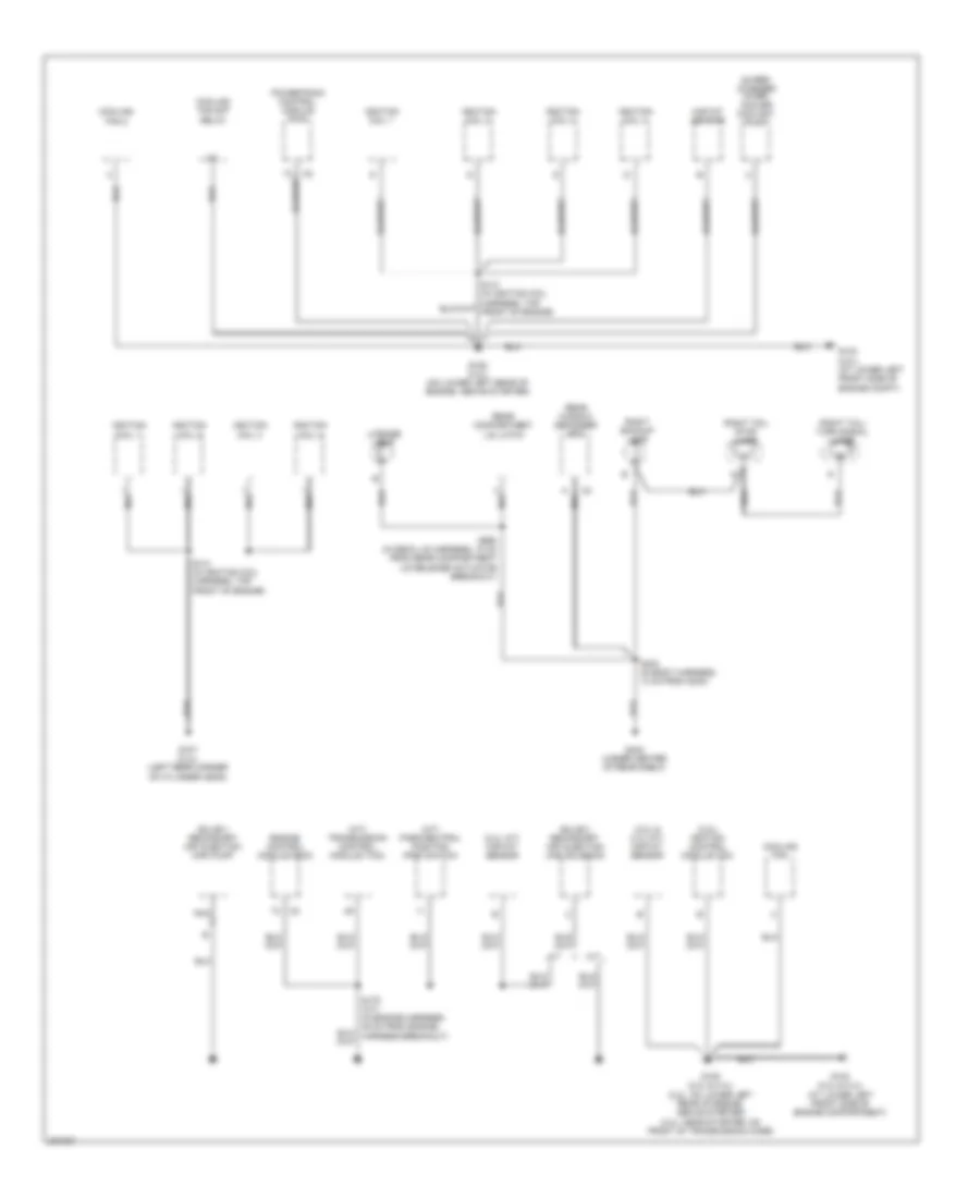
Ground Distribution Wiring Diagram (3 of 3) for Saturn Ion 2 2006
List of elements for Ground Distribution Wiring Diagram (3 of 3) for Saturn Ion 2 2006:
- (2.2l & 2.4l m/t) maf/iat sensor
- (2.2l) ignition control module (icm)
- (2.4l a/t) maf/iat sensor
- (a/t) park/neutral position (pnp) switch
- (a/t) transmission control module (tcm)
- (sulev) secondary air injection (air) pump
- (sulev) secondary air injection (air) solenoid
- A/t
- Cooling fan
- Cooling fan 2
- Cooling fan s/p relay
- Engine control module (ecm)
- G103 (2.0l) (at lower left front side of engine compt)
- G103 (2.2l & 2.4l) (at lower left front side of engine compartment)
- G105 (2.0l) (on lower left rear of engine, above starter)
- G105 (2.2l & 2.4l) (2.2l: on lower left rear of engine, above starter) (2.4l: near starter, on front of transmission case)
- G107 (2.4l) (left rear corner of cylinder head)
- G403 (under center of rear shelf)
- Ignition coil 1
- Ignition coil 2
- Ignition coil 3
- Ignition coil 4
- License lamp
- M/t
- Maf/iat sensor
- Nca
- Powertrain control module (pcm)
- Rear compartment lid latch
- Rear window defogger grid
- Right backup lamp
- Right tail/ stop lamp
- Right tail/ turn signal lamp
- S141 (in ignition coil harness, top front of engine)
- S403 (in body harness, 13 cm from g403)
- S990 (in deck lid harness, 10 cm from rear compartment lid release actuator breakout)
- Super- charger inter- cooler coolant pump
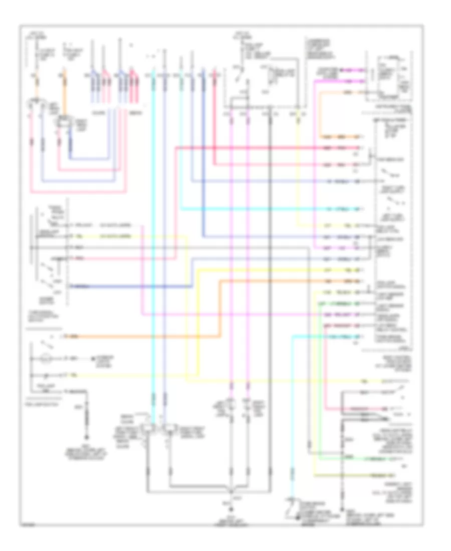
HEADLIGHTS
Headlights Wiring Diagram for Saturn Ion 2 2006
List of elements for Headlights Wiring Diagram for Saturn Ion 2 2006:
- (deluxe) (front)
- (w/ auto lamps)
- A10
- Ambient light sensor (2.2l, w/ auto lamps) (on top left side of dash)
- Auto
- B+ voltage
- B10
- Body control module (bcm) (at lower center of dash)
- C11
- C12
- C2 f4
- C3 a12
- Class 2 serial data 2
- Cluster fuse 7.5a
- Computer data lines system
- Coupe
- D11
- D12
- Dimmer switch
- E10
- E12
- F12
- Flash
- Fog lamp fuse 17 10a 15a
- Fog lamp ind
- Fog lamp relay 26
- Fog lamp relay ctrl
- Fog lamp switch
- Fog lamp switch signal
- G10
- G101 (behind left front headlamp)
- G12
- G201 (behind lower left side of dash, left of steering column)
- G203 (behind lower left side of dash, left of steering column)
- H10
- H12
- Head
- Headlamp relay (2.2l, w/ auto lamps) (behind lower left side of dash, near data link connector (dlc))
- Headlamp switch
- Headlamps off signal
- High
- High beam ind
- High beam sig
- Hot at all times
- Instrument panel cluster
- Interior lights system
- Ipc class 2 serial data
- Left front fog lamp b
- Left front park/turn signal lamp
- Left head- lamp
- Lh hdlp fuse 18 15a
- Light sensor low ref
- Light sensor signal
- Logic
- Low
- Low beam relay control
- Low beam sig
- Off
- Park
- Park brake switch (under center console, attached to emergency brake)
- Park brake switch signal
- Pnk
- Rh hdlp fuse 4 15a
- Right front fog lamp
- Right front park/turn signal lamp
- Right head- lamp
- S101
- S221
- S233
- S260
- Sedan
- Turn signal/ multi-function switch
- Underhood fuse block (at left rear side of engine compt)
HORN
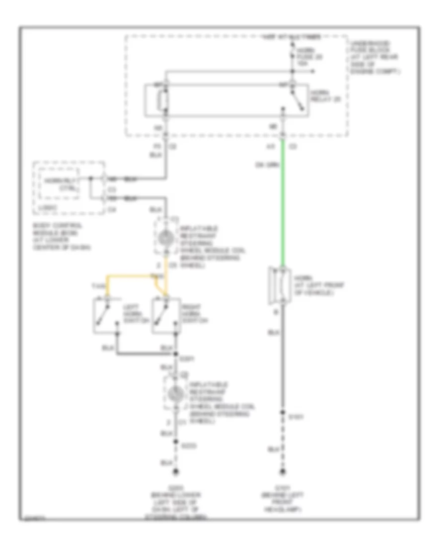
Horn Wiring Diagram for Saturn Ion 2 2006
List of elements for Horn Wiring Diagram for Saturn Ion 2 2006:
- Body control module (bcm) (at lower center of dash)
- F5 c2
- G101 (behind left front headlamp)
- G203 (behind lower left side of dash, left of steering column)
- Horn (at left front of vehicle)
- Horn fuse 20 10a
- Horn relay 25
- Horn rly ctrl
- Hot at all times
- Inflatable restraint steering wheel module coil (behind steering wheel)
- Left horn switch
- Logic
- Right horn switch
- S101
- S201
- S233
- Tan
- Underhood fuse block (at left rear side of engine compt)
INSTRUMENT CLUSTER
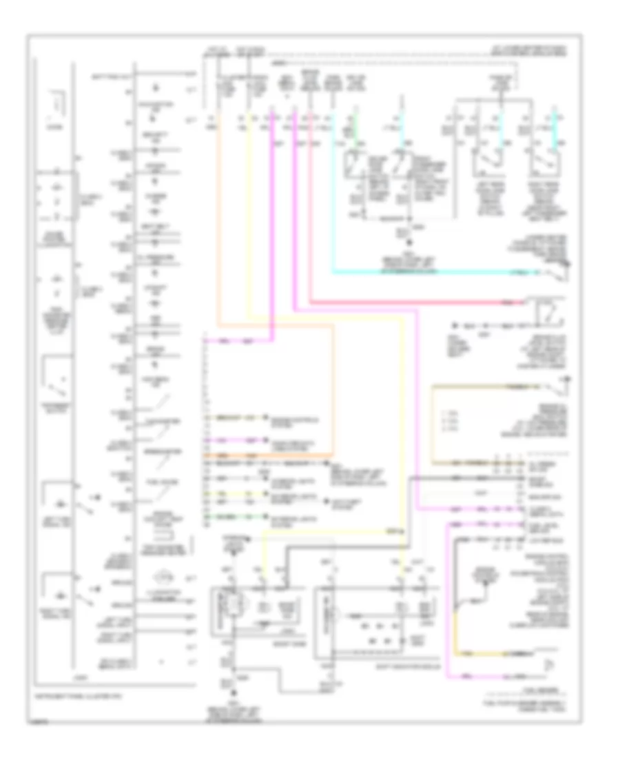
Instrument Cluster Wiring Diagram for Saturn Ion 2 2006
List of elements for Instrument Cluster Wiring Diagram for Saturn Ion 2 2006:
- (at lower center of dash) body control module (bcm)
- (under center console, attached to emergency brake) park brake switch
- 2.0l
- 2.2l
- 2.4l
- Abs ind
- Air bag ind
- Anti-theft system
- Backlight ind
- Batt pos volt
- Bcm serial data
- Boost gage
- Boost gage sig
- Brake fluid level sen sig
- Brake fluid level switch (at left rear of engine compt, attached to master cylinder)
- Brake ind
- Charge ind
- Chime
- Class 2 (bcm)
- Class 2 (bcm/ecm/ eps/ebcm)
- Class 2 (ebcm)
- Class 2 (ecm)
- Class 2 (ecm/tcm)
- Class 2 (sdm)
- Class 2 serial data
- Cluster/ aos fuse 7.5a
- Computer data lines system
- Driver door jamb switch (behind left i/p access panel)
- Drv dr jamb sw sig
- Eng spd sig
- Engine control module (ecm) (2.2l/2.4l) powertrain control module (pcm) (2.0l) (2.2l/2.4l: at left side of engine compt) (2.0l: at rear of engine, near coolant overflow container)
- Engine controls system
- Engine coolant temp gauge
- Engine oil pressure (eoc) switch (w/ low pressure) (2.0l: lower rear of engine, above starter)
- Exterior lights system
- Front passenger door jamb switch (right front of dash, on outer trim cover)
- Fuel gauge
- Fuel level sen sig
- Fuel pump & sender assembly (inside fuel tank)
- Fuel sender
- G201 (behind lower left side of dash, left of steering column)
- G301 (under driver's seat)
- Gauge pointer illumination
- Gnd
- Ground
- High beam ind
- Hot at all times
- Hot in run or start
- Ign 1 volt
- Illumination (6 bulbs)
- Instrument panel cluster (ipc)
- Interior lights system
- Ipc class 2 serial data
- Left rear door jamb switch (sedan) (in right "b" pillar)
- Left turn signal ind
- Left turn signal input
- Logic
- Low ref bus
- Malfunction ind
- Nca
- Oil press sw sig
- Oil pressure ind
- Park brake sw sig
- Pass dr jamb sw sig
- Pnk
- Radio (acc) fuse 10a
- Right rear door jamb switch (sedan) (near front left passenger seat belt)
- Right turn signal ind
- Right turn signal input
- S200
- S221
- S250
- S351
- Seat belt ind
- Security ind
- Shift indicator module
- Shift leds
- Speedometer
- Tachometer
- Tan
- Trip odometer/ message center
- Trip/ odometer message center illum
- Trip/reset switch
- Up-shift ind
INTERIOR LIGHTS
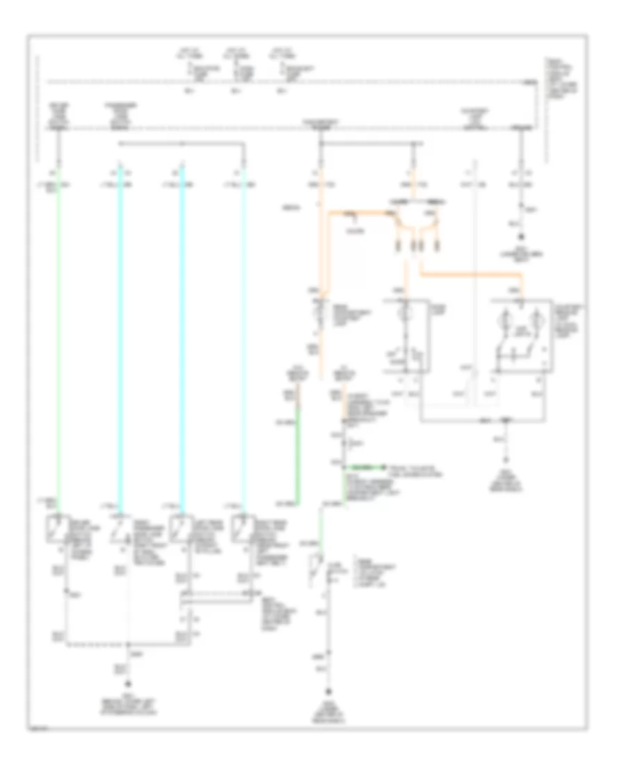
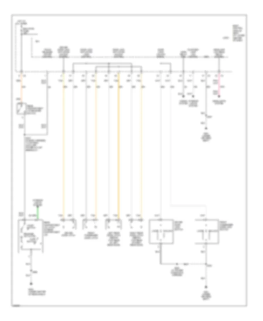
Courtesy Lamps Wiring Diagram for Saturn Ion 2 2006
List of elements for Courtesy Lamps Wiring Diagram for Saturn Ion 2 2006:
- (in body harness, 7.5 cm from left rear speaker breakout) s411
- Ajar switch
- B(+)
- Bcm (pwr) fuse 15a
- Bcm elect fuse 20a
- Body control module (bcm) (at lower center of dash)
- Coupe
- Courtesy lamp low control
- Courtesy/ reading lamp (w/ dual reading lamp)
- D401
- Dash fuse 7.5a
- Dome lamp
- Door
- Driver door jamb switch (behind left i/p access panel)
- Driver door jamb switch signal
- Front passenger door jamb switch (right front of dash, on outer trim cover)
- G201 (behind lower left side of dash, left of steering column)
- G301 (under driver's seat)
- G401 (under center of rear shelf)
- G403 (under center of rear shelf)
- Ground
- Hot at all times
- Inadvertent power
- Left rear door jamb switch (sedan) (in right "b" pillar)
- Logic
- Map lights
- Nca
- Off
- Passenger door jamb switch signal
- Rear compartment courtesy lamp
- Rear compartment lid latch (in rear compt lid)
- Right rear door jamb switch (sedan) (near front left passenger seat belt)
- S221
- S250
- S351
- S375
- S413 (in body harness, 7.5 cm from rear compartment light breakout)
- S990
- Sedan
- Trunk, tailgate, fuel doors system
- W/ remote entry
- W/o remote entry
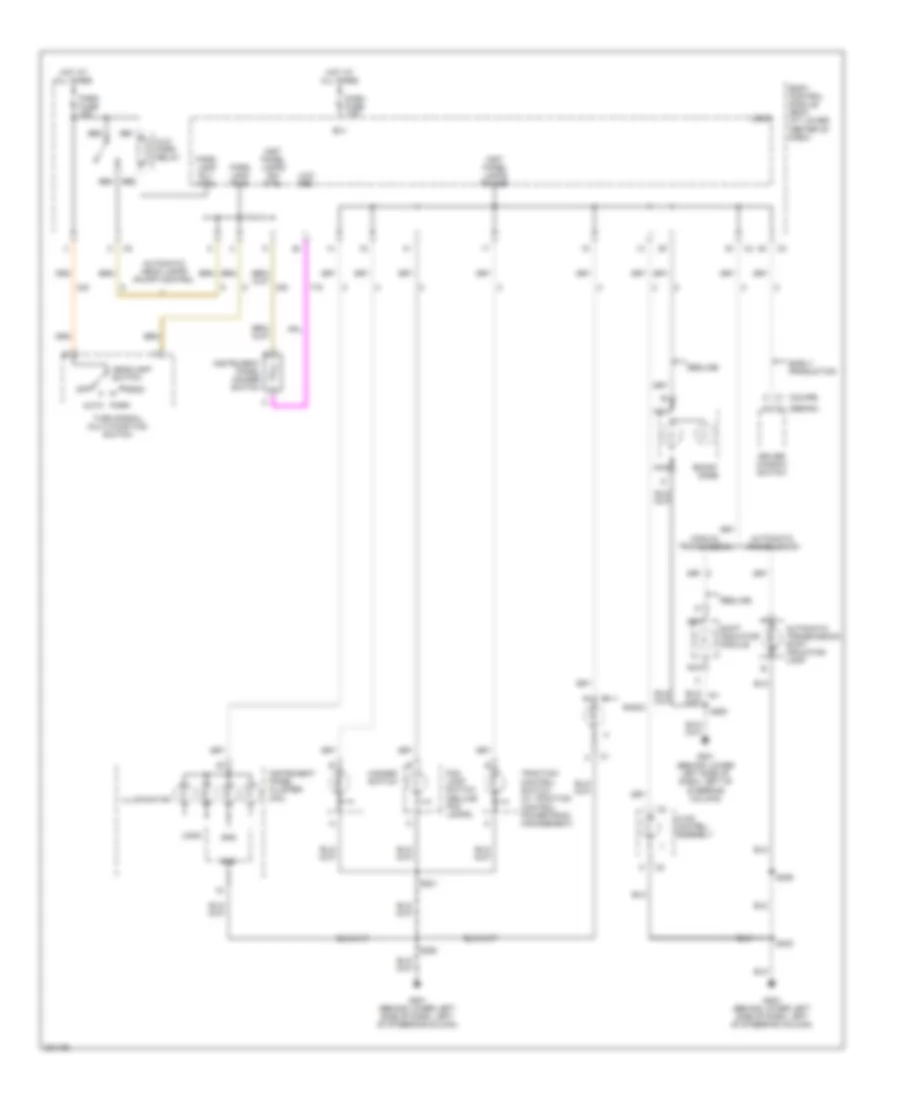
Instrument Illumination Wiring Diagram for Saturn Ion 2 2006
List of elements for Instrument Illumination Wiring Diagram for Saturn Ion 2 2006:
- (coupe)
- (sedan)
- A c1
- Alc/ park relay
- Auto
- Automatic head lamps on-off control
- Automatic transmission
- Automatic transmission shift indicator lamp
- B(+)
- Bb1
- Bb2
- Bb3
- Bb4
- Body control module (bcm) (at lower center of dash)
- Boost gage
- C c1
- Dash fuse 7.5a
- Driver window switch
- Early production
- Fog lamp switch (deluxe fog lamps)
- G201 (behind lower left side of dash, left of steering column)
- G203 (behind lower left side of dash, left of steering column)
- Gnd
- Hazard switch
- Head
- Headlamp switch
- Hot at all times
- Hvac control assembly
- Illumination
- Inst panel lamps dim ctrl
- Inst panel lamps power
- Instrument panel cluster (ipc)
- Instrument panel dimmer switch
- Logic
- Low ref
- Manual transmission
- Nca
- Off
- Park
- Park fuse 15a
- Park lamp pwr
- Park lamp rly ctrl
- Radio
- Redline
- S221
- S233
- S250
- S355
- Shift indicator module
- Traction control switch (w/ traction control powertrain management)
- Turn signal/ multi-function switch
POWER DISTRIBUTION
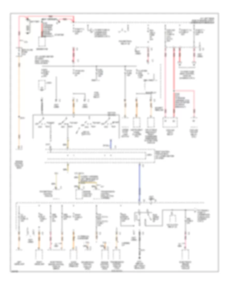
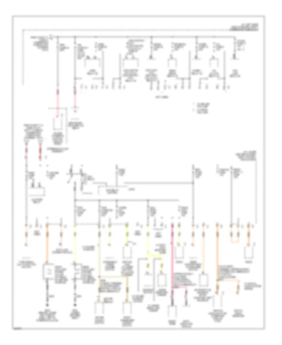
Power Distribution Wiring Diagram (1 of 3) for Saturn Ion 2 2006
List of elements for Power Distribution Wiring Diagram (1 of 3) for Saturn Ion 2 2006:
- (at left rear side of engine compt) underhood fuse block
- (at lower center of dash) body control module (bcm)
- (not used)
- (or rust)
- 2.0l
- 2.2l
- 2.2l & 2.4l
- 2.4l
- 4 speed a/t
- 5v ref
- A/c clutch relay 24
- A/t
- A10
- A11
- Aa2
- Aa3
- Abs fuse 22 20a
- Abs fuse 40a
- Abs fuse 8 10a
- Acc
- Audio amplifier (premium)
- B1 c2
- B11 c2
- Ba2
- Battery
- Bcm elect fuse 20a
- Body control module (bcm) (at lower center of dash)
- C1 engine control module
- Cluster/ aos fuse 7.5a
- Cooling fan 2 fuse 44 (2.0l & 2.4l) 30a
- Cooling fan 2 relay
- Cooling fan s/p relay (2.0l)
- E4 c2
- Ecm inline fuse 10a
- Electronic brake control module
- Electronic brake control module (ebcm)
- Engine control module (ecm)
- Engine control module (pcm)
- Except redline
- Fuel pump fuse 15a
- Fuel pump relay
- G101 (behind left front headlamp)
- Generator
- I/p/ign sw fuse 2a
- Ignition switch
- Inflatable restraint front passenger prescence system (pps) module
- Instrument panel cluster (ipc)
- Ip batt 1 fuse 39 30a
- Ip batt 1a fuse 47 30a
- Ip batt 2 fuse 41 40a
- Key-in switch
- Left headlamp
- Left rear side of engine compt) s104
- Lh hdlp fuse 18 15a
- Logic
- Off
- Pnk
- Powertrain control module
- Powertrain control module (pcm)
- Powertrain relay 29
- Radio fuse 21 20a
- Red
- Rh hdlp fuse 4 15a
- Right headlamp
- Run
- Run (ign 3) fuse 30a
- Run relay
- Run/ crank fuse 38 30a
- Run/ crank relay
- S101
- S150 (in engine harness, 5 cm from engine harness breakout) red
- S158 (2.0l) (in engine harness, 6 cm from starter solenoid breakout)
- S310
- Start
- Starter
- Stop fuse 15a
- Tcm (2.2l & 2.4l) ecm (2.0l & 2.4l) fuse 1 10a
- To eps fuse 43 (underhood fuse block) (diagram 2 of 3)
- To park fuse (body control module) (diagram 2 of 3)
- To trans 2 fuse 13 (underhood fuse block) (diagram 3 of 3)
- Transmission control module (tcm) (2.2l & 2.4l)
- Transmission control module (tcm) (4 speed)
- Upper stop lamp switch
- W/ abs
- W/ premium 6 speaker
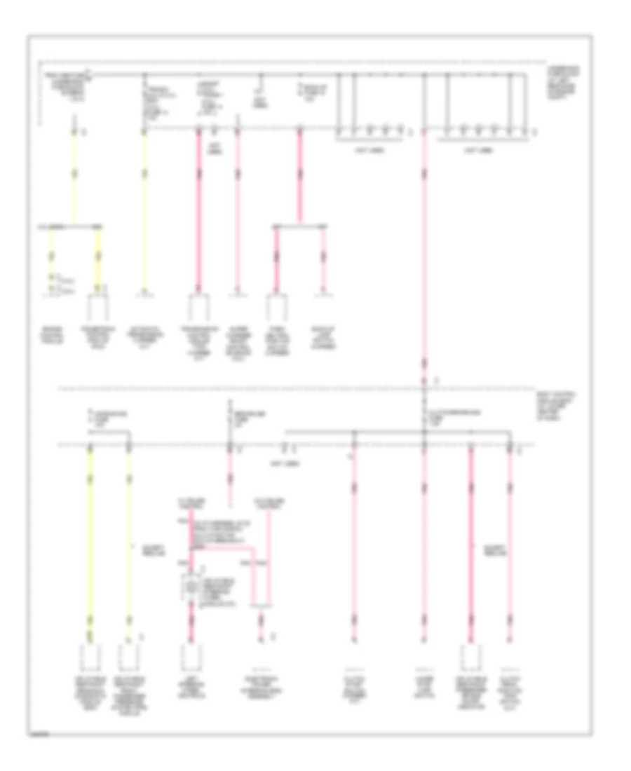
Power Distribution Wiring Diagram (2 of 3) for Saturn Ion 2 2006
List of elements for Power Distribution Wiring Diagram (2 of 3) for Saturn Ion 2 2006:
- (approximately 22 cm from turn signal/ multifunction switch breakout) s200
- (at left rear side of engine compt) underhood fuse block
- (at lower center of dash) body control module (bcm)
- (coupe)
- (in aux body harness, approximately 5 cm from g401 breakout) (w/ digital audio system) s417
- (not used)
- (sedan) c1
- 15a
- A/c clutch relay 24
- A/c fuse 5 10a
- A/t
- Ab1
- Ab2
- Ab3
- Ab4
- Acc relay
- Acc relay control
- Air pump rly fuse (2.2l & sulev) 40a
- Alc/park relay
- Bb1
- Bb3
- Bcm (pwr) fuse 15a
- Boost gage
- Cooling fan (2.2l & 2.4l) cooling fan 1 (2.0l) relay 30
- Cooling fan 1 (2.0l) cooling fan (2.2l & 2.4l) fuse 45 30a
- Crank fuse 46 30a
- D12
- Dash fuse 7.5a
- Data link connector (dlc)
- Digital radio receiver
- Driver window switch
- E10
- E12
- Eps fuse 43 60a
- Evaporative emission (evap) canister vent solenoid
- F12
- Fog lamp relay 26
- From ip batt 1a fuse 47 & ip batt 1 fuse 39 (underhood fuse block) (diagram 1 of 3)
- From ip batt 2 a fuse 41 (underhood fuse block) (diagram 1 of 3)
- Front auxiliary power outlet (at front of center console)
- Front passenger window switch
- G10
- G203 (behind lower left side of dash, left of steering column)
- G301 (under driver's seat)
- Horn fuse 20 10a
- Horn relay 25
- Ignition lock cylinder control actuator (4 speed)
- Inside rearview mirror
- Lighter fuse 15a
- Logic
- Lp fog fuse 17 10a
- Nca
- Onstar fuse 10a
- Park fuse 15a
- Pcm cont (2.0l) ecm cont (2.2l & 2.4l) relay 31
- Pnk
- Power steering control module (pscm)
- Pwr outlet fuse 15a
- Pwr windows fuse 30a
- Radio
- Radio (acc) fuse 10a
- Radio (batt 1) fuse 15a
- Rear auxiliary power outlet (at rear of center console)
- Rear compartment lid release switch
- Rear defog relay 34
- Red
- Rr defog fuse 23 30a
- Secondary air injection relay
- Shift indicator module
- Steering column assembly
- Sun roof fuse 15a
- Sunroof switch
- Turn signal/ multi-function switch
- V12
- Vehicle communication interface module (vcim)
- W/ deluxe fog lamp
- W/ digital audio system s-band
- W/ front fog lamp
- W/ inside rear view mirror
- W/ power sunroof sliding
- W/ power windows
- W/ shift light booster gage
- Windshield wiper/ washer switch
- Wiper 1 relay 32
- Wiper fuse 19 25a
- Wiper sw fuse 10a
Power Distribution Wiring Diagram (3 of 3) for Saturn Ion 2 2006
List of elements for Power Distribution Wiring Diagram (3 of 3) for Saturn Ion 2 2006:
- (2.2l) c1
- (2.4l) c1
- (not used)
- 2.0l
- 2.2l & 2.4l
- A/t
- A10
- Air bag/aos fuse 10a
- Automatic transmission (4 speed a/t)
- Back-up fuse 15 10a
- Back-up lamp switch (5 speed)
- Body control module (bcm) (at lower center of dash)
- Boost (2.0l) trans 1 (2.2l) fuse 14 10a
- Clutch pedal position (cpp) switch (m/t)
- Clutch start switch (5 speed m/t)
- Clutch/brake/aos fuse 7.5a
- Electronic power steering (eps) assembly
- Engine control module
- Eps/cruise fuse 2a
- Except redline
- From abs fuse d (underhood fuse block) (diagram 1 of 3)
- Inflatable restraint front passenger presence system (pps) module
- Inflatable restraint passenger air bag on/off indicator
- Inflatable restraint sensing & diagnostic module (sdm)
- Inflatable restraint steering wheel module coil
- Left steering wheel controls
- Lower stop lamp switch
- M/t
- Park/ neutral position switch (4 speed)
- Pnk
- Pnk (in i/p harness, 22 cm from turn signal/ multi-function switch breakout) s227
- Powertrain control module (pcm)
- Super charger boost control solenoid (2.0l)
- Trans 2 (2.2l & 2.4l) ecm (2.0l) fuse 13 10a
- Transmission control module (tcm) (4 speed a/t)
- Underhood fuse block (at left rear side of engine compt)
- W/ cruise control
- W/o cruise control
POWER DOOR LOCKS
Power Door Locks Wiring Diagram for Saturn Ion 2 2006
List of elements for Power Door Locks Wiring Diagram for Saturn Ion 2 2006:
- Ajar switch
- B(+)
- Bcm (pwr) fuse 15a
- Body control module (bcm) (at lower center of dash)
- Courtesy lamp low control
- Door lock actuator lock control
- Door lock actuator unlock control
- Door lock/ unlock signal
- Driver door latch
- Driver door lock actuator unlock control
- Driver door lock switch
- Front passenger door latch
- Front passenger door lock switch
- G301 (under driver's seat)
- G403 (under center of rear shelf)
- Gnd
- Headlamp low beam relay control
- Headlights system
- Horn relay ctrl
- Horns system
- Hot at all times
- Interior lights system
- Left rear door latch (sedan) (top rear of left rear door)
- Lock
- Logic
- Rear compartment lid latch (in rear compartment lid)
- Rear compartment lid release switch
- Release actuator m
- Right rear door latch (sedan) (top rear of right rear door)
- S337 (in body harness, 7.5 cm from auxiliary power outlet breakout)
- S351
- S533 (w/ power windows & mirrors)
- S990
- Tan
- Trunk release motor control
- Unlock
- Valet switch
POWER MIRRORS
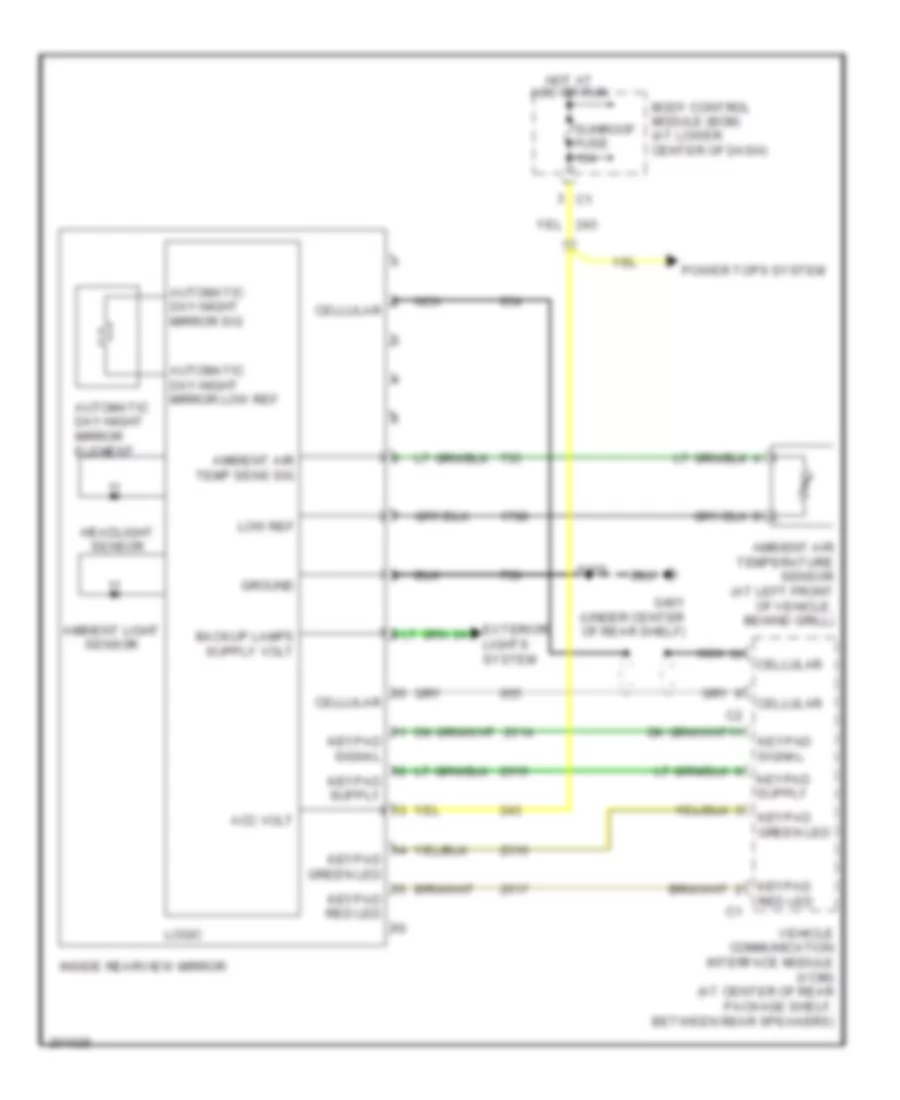
Electrochromic Mirror Wiring Diagram for Saturn Ion 2 2006
List of elements for Electrochromic Mirror Wiring Diagram for Saturn Ion 2 2006:
- Acc volt
- Ambient air temp sens sig
- Ambient air temperature sensor (at left front of vehicle, behind grill)
- Ambient light sensor
- Automatic day-night mirror element
- Automatic day-night mirror low ref
- Automatic day-night mirror sig
- Body control module (bcm) (at lower center of dash)
- Cellular
- Exterior lights system
- G401 (under center of rear shelf)
- Ground
- Headlight sensor
- Hot at acc or run
- Inside rearview mirror
- Keypad green led
- Keypad red led
- Keypad signal
- Logic
- Low ref
- Nca
- Power tops system
- S375
- Sunroof fuse 15a
- Vehicle communication interface module (vcim) (at center of rear package shelf, between rear speakers)
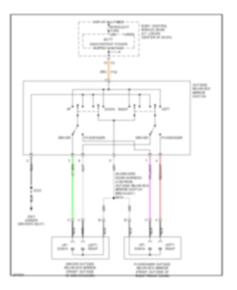
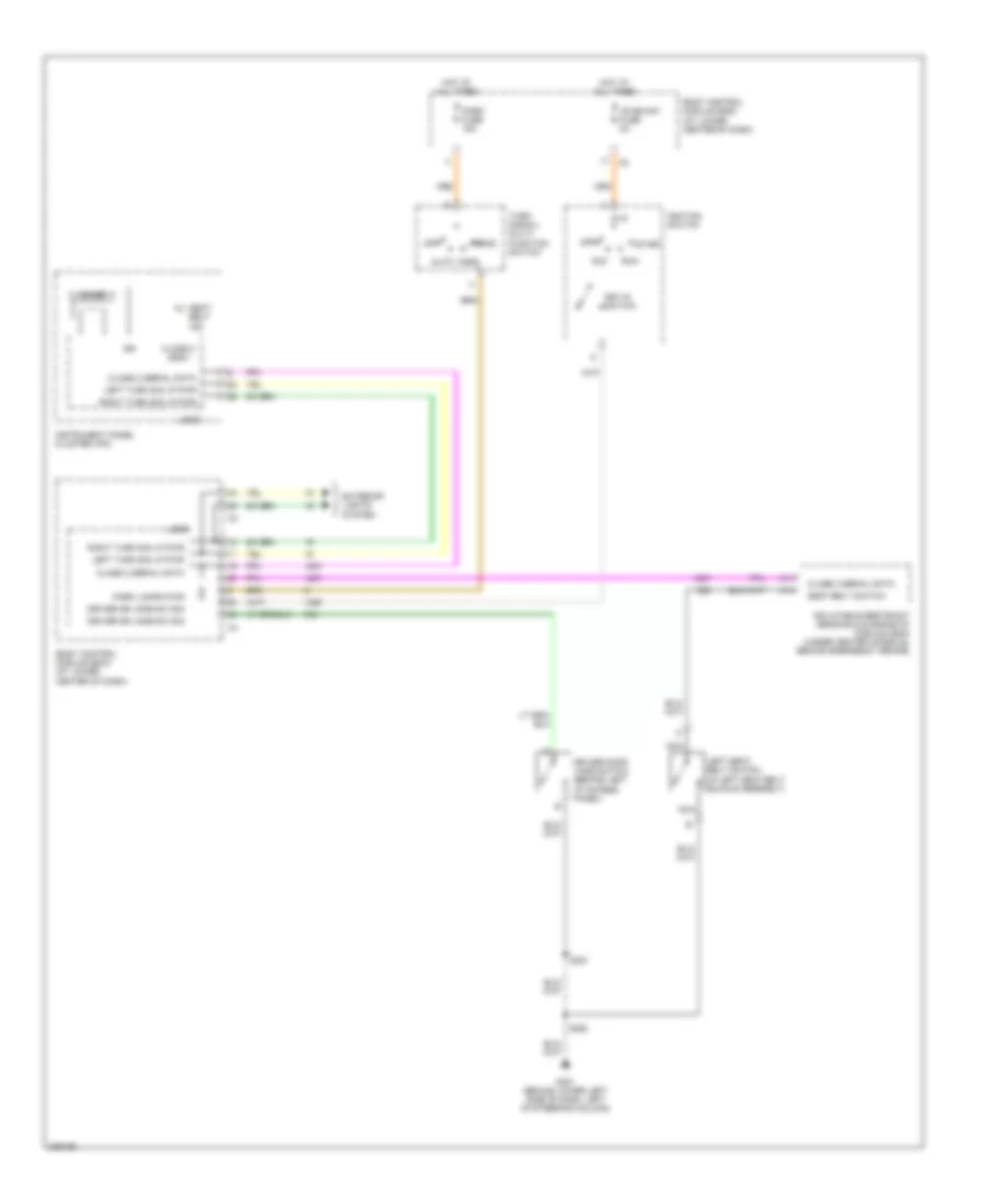
Power Mirrors Wiring Diagram for Saturn Ion 2 2006
List of elements for Power Mirrors Wiring Diagram for Saturn Ion 2 2006:
- (in driver's door harness, 4 cm from outside rearview mirror switch breakout) s511
- Batt
- Bcm elect fuse 20a
- Body control module (bcm) (at lower center of dash)
- Down
- Driver
- Driver outside rearview mirror (front outside of driver door)
- G301 (under driver's seat)
- Hot at all times
- Left
- Left/ right
- Logic
- Nca
- Outside rearview mirror switch
- Passenger
- Passenger outside rearview mirror (front outside of right front door)
- Right
- S533
- Up/ down
POWER TOP/SUNROOF
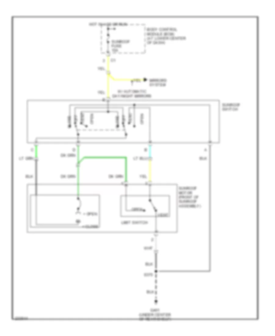
Power Top/Sunroof Wiring Diagram for Saturn Ion 2 2006
List of elements for Power Top/Sunroof Wiring Diagram for Saturn Ion 2 2006:
- + close
- + open
- Body control module (bcm) (at lower center of dash)
- Close
- G401 (under center of rear shelf)
- Hot in acc or run
- Limit switch
- Mirrors system
- Off
- Open
- S375
- Sunroof fuse 15a
- Sunroof motor (front of sunroof assembly)
- Sunroof switch
- Vent
- W/ automatic day/night mirrors
POWER WINDOWS
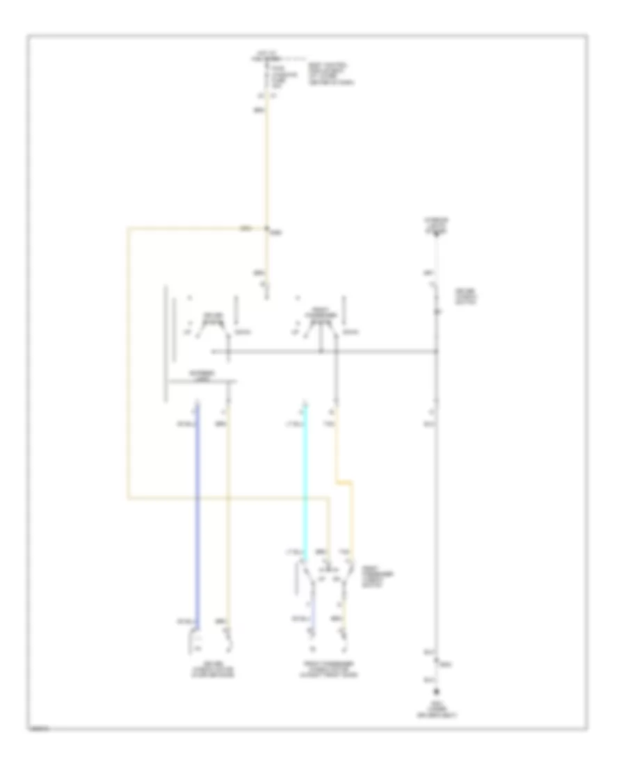
Power Windows Wiring Diagram, Coupe for Saturn Ion 2 2006
List of elements for Power Windows Wiring Diagram, Coupe for Saturn Ion 2 2006:
- Body control module (bcm) (at lower center of dash)
- Down
- Driver switch
- Driver window motor (in driver door)
- Driver window switch
- Express logic
- Front passenger switch
- Front passenger window motor (in right front door)
- Front passenger window switch
- G301 (under driver's seat)
- Hot at all times
- Interior lights system
- Pwr windows fuse 30a
- S360
- S533
- Tan
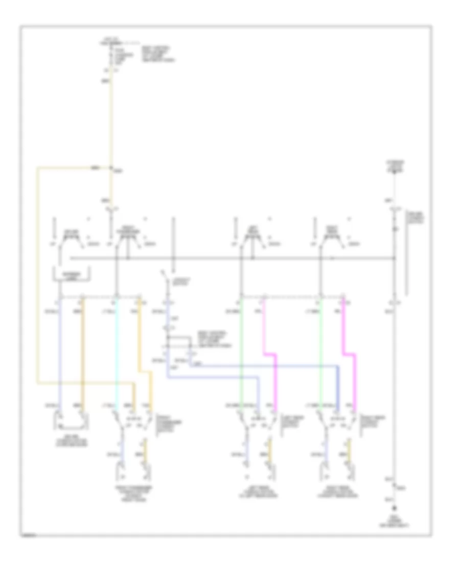
Power Windows Wiring Diagram, Sedan for Saturn Ion 2 2006
List of elements for Power Windows Wiring Diagram, Sedan for Saturn Ion 2 2006:
- Body control module (bcm) (at lower center of dash)
- C1 d
- C1 e
- C2 a
- C2 h
- Down
- Driver switch
- Driver window motor (in driver door)
- Driver window switch
- Express logic
- Front passenger switch
- Front passenger window motor (in right front door)
- Front passenger window switch
- G301 (under driver's seat)
- Hot at all times
- Interior lights system
- Left rear switch
- Left rear window motor (in left rear door)
- Left rear window switch
- Lockout switch
- Pwr windows fuse 30a
- Right rear switch
- Right rear window motor (in right rear door)
- Right rear window switch
- S360
- S533
- Tan
RADIO
Radio Wiring Diagram, with Amplifier for Saturn Ion 2 2006
List of elements for Radio Wiring Diagram, with Amplifier for Saturn Ion 2 2006:
- (at center of rear package shelf, between rear speakers) (if equipped) vehicle communication interface module (vcim)
- (in driver's door harness, 11.5 cm from driver's out side rearview mirror breakout)
- (in right front passenger's door harness, 5.5 cm from right front door tweeter speaker breakout)
- Accessory volt
- Amplifier mute sig
- Amplifier mute signal
- Antenna sig
- Audio amplifier (in trunk, below rear shelf)
- Audio common
- Audio out (-)
- Battery pos volt
- Battery voltage +
- Body control module (bcm) (at lower center of dash)
- Cellular mute sig
- Cellular telephone mute sig
- Cellular telephone voice sig c2
- Coax
- Computer data lines system
- Data link connector (dlc) (under lower left side of dash)
- Dimming
- Drain wire
- G201 (behind lower left side of dash, left of steering column)
- G401 (under center of rear shelf)
- Ground
- Hot at all times
- Hot in acc or run
- I/p lamp sply volt
- Left audio sig
- Left audio sig (+)
- Left front door speaker
- Left front door tweeter speaker
- Left rear speaker
- Left sub spkr out (+)
- Left sub spkr out (-)
- Lf speaker out (+)
- Lf speaker out (-)
- Lf spkr out (+)
- Lf spkr out (-)
- Logic
- Low reference
- Lr speaker out (+)
- Lr speaker out (-)
- Lr spkr out (+)
- Lr spkr out (-)
- Nca
- Park lamp sply volt
- Pnk
- Radio
- Radio (acc) fuse 10a
- Radio (batt 1) fuse 15a
- Radio antenna
- Radio fuse 21 20a
- Radio on sig
- Radio on signal
- Rf speaker out (+)
- Rf speaker out (-)
- Rf spkr out (+)
- Rf spkr out (-)
- Right audio sig (+)
- Right front door speaker
- Right front door tweeter speaker
- Right rear speaker
- Right sub spkr out (+)
- Right sub spkr out (-)
- Rr speaker out (+)
- Rr speaker out (-)
- Rr spkr out (+)
- Rr spkr out (-)
- S250
- S401
- S555 (in driver's door harness, 19 cm from driver's outside rearview mirror breakout)
- S557
- S656 (in right front passenger's door harness, 13 cm from right front door tweeter speaker breakout)
- S658
- Satellite radio circuit
- Serial data
- Tan
- Underhood fuse block (at left rear side of engine compt)
Radio Wiring Diagram, without Amplifier for Saturn Ion 2 2006
List of elements for Radio Wiring Diagram, without Amplifier for Saturn Ion 2 2006:
- (at center of rear package shelf, between rear speakers) (if equipped) vehicle communication interface module (vcim)
- (not used)
- Accessory volt
- Amplifier mute sig
- Antenna sig
- Audio common
- Audio out (-)
- Battery voltage +
- Body control module (bcm) (at lower center of dash)
- Cellular mute sig
- Cellular telephone mute sig
- Cellular telephone voice sig
- Coax
- Computer data lines system
- Data link connector (dlc) (under lower left side of dash)
- Dimming
- Drain wire
- G201 (behind lower left side of dash, left of steering column)
- Ground
- Hot at all times
- Hot in acc or run
- I/p lamp sply volt
- Left audio sig
- Left audio sig (+)
- Left front door speaker
- Left rear speaker
- Lf spkr out (+)
- Lf spkr out (-)
- Logic
- Low reference
- Lr spkr out (+)
- Lr spkr out (-)
- Nca
- Park lamp sply volt
- Radio
- Radio (acc) fuse 10a
- Radio (batt 1) fuse 15a
- Radio antenna
- Radio on sig
- Rf spkr out (+)
- Rf spkr out (-)
- Right audio sig (+)
- Right front door speaker
- Right rear speaker
- Rr spkr out (+)
- Rr spkr out (-)
- S250
- Satellite radio circuit
- Serial data
- Tan
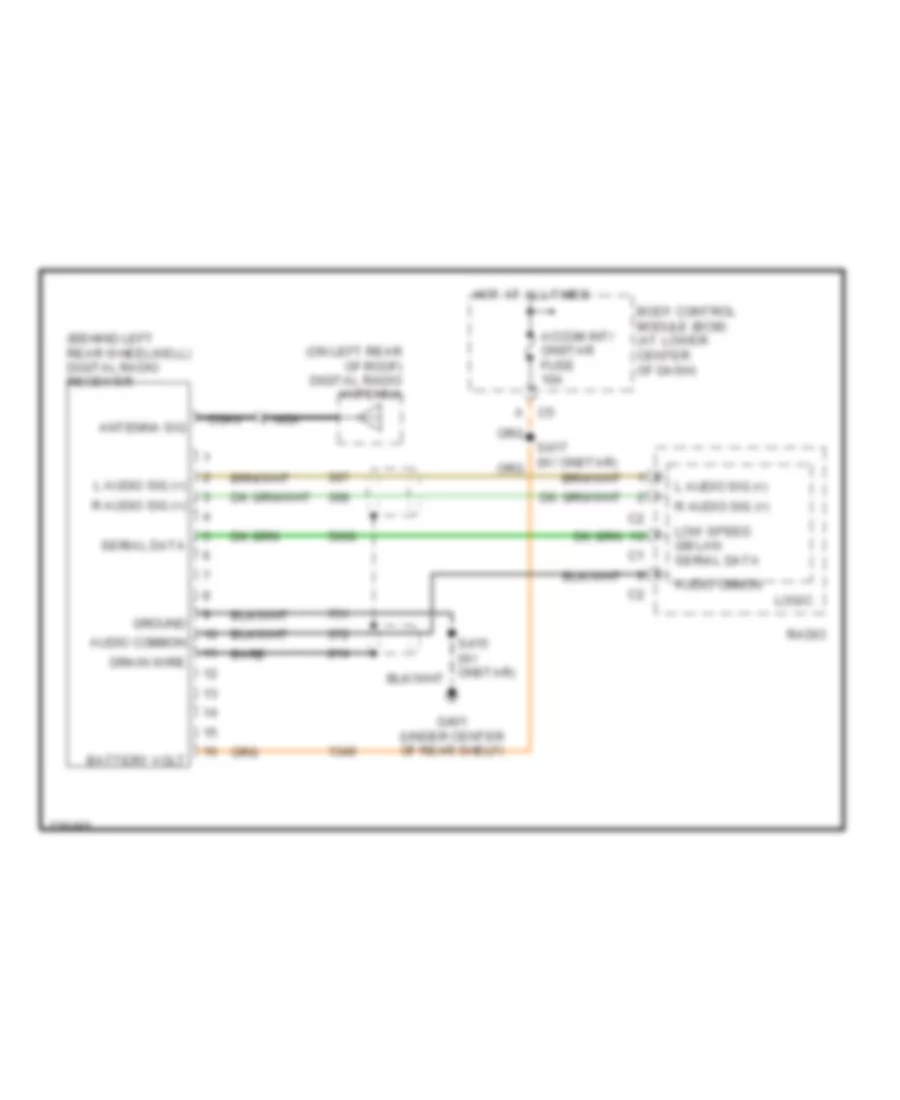
Satellite Radio Wiring Diagram for Saturn Ion 2 2006
List of elements for Satellite Radio Wiring Diagram for Saturn Ion 2 2006:
- (behind left rear wheelwell) digital radio receiver
- (on left rear of roof) digital radio antenna
- Accom int/ onstar fuse 10a
- Antenna sig
- Audio cmmon
- Audio common
- Bare
- Battery volt
- Body control module (bcm) (at lower center of dash)
- C5 a
- Coax
- Drain wire
- G401 (under center of rear shelf)
- Ground
- Hot at all times
- L audio sig (+)
- Logic
- Low speed gm lan serial data
- Nca
- R audio sig (+)
- Radio
- Serial data
SHIFT INTERLOCK
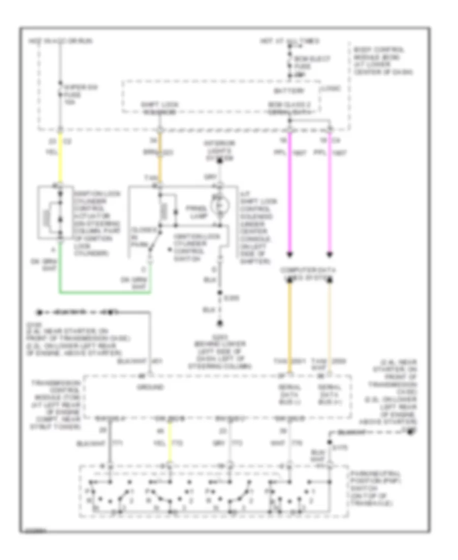
Shift Interlock Wiring Diagram for Saturn Ion 2 2006
List of elements for Shift Interlock Wiring Diagram for Saturn Ion 2 2006:
- (2.4l: near starter, on front of transmission case) (2.2l: on lower left rear of engine, above starter) g105
- A/t shift lock control solenoid (under center console, on left side of shifter)
- Battery
- Bcm class 2 serial data
- Bcm elect fuse 20a
- Body control module (bcm) (at lower center of dash)
- Closes in park
- Computer data lines system
- G105 (2.4l: near starter, on front of transmission case) (2.2l: on lower left rear of engine, above starter)
- G203 (behind lower left side of dash, left of steering column)
- Ground
- Hot at all times
- Hot in acc or run
- Ignition lock cylinder control actuator (on steering column, part of ignition lock cylinder)
- Ignition lock cylinder control switch
- Interior lights system
- Logic
- Park/neutral position (pnp) switch (on top of transaxle)
- Prndl lamp
- R n
- S175
- S355
- Serial data bus (+)
- Serial data bus (-)
- Shift lock solenoid
- Sw sig a
- Sw sig b
- Sw sig c
- Sw sig d
- Tan
- Tan b
- Tan/
- Transmission control module (tcm) (at left rear of engine compt, near strut tower)
- Wiper sw fuse 10a
STARTING/CHARGING
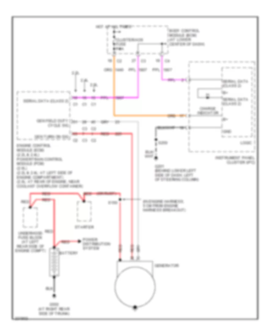
Charging Wiring Diagram for Saturn Ion 2 2006
List of elements for Charging Wiring Diagram for Saturn Ion 2 2006:
- (in engine harness, 5 cm from engine harness breakout)
- (or rust)
- 2.0l
- 2.2l
- 2.4l
- Battery
- Body control module (bcm) (at lower center of dash)
- Charge indicator
- Cluster/aos fuse 7.5a
- Cycle sig
- Engine control module (ecm) (2.2l & 2.4l) powertrain control module (pcm) (2.0l) (2.2l & 2.4l: at left side of engine compartment) (2.0l: at rear of engine, near coolant overflow container)
- G201 (behind lower left side of dash, left of steering column)
- G502 (at right rear side of trunk)
- Gen field duty
- Gen turn on sig
- Generator
- Gnd
- Hot at all times
- Instrument panel cluster (ipc)
- Logic
- Power distribution system
- Red
- S150
- S250
- Serial data (class 2)
- Starter
- Underhood fuse block (at left rear side of engine compt)
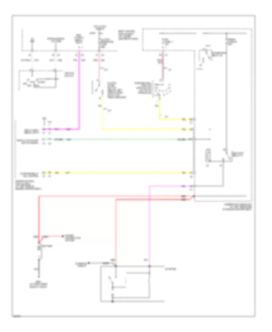
Starting Wiring Diagram for Saturn Ion 2 2006
List of elements for Starting Wiring Diagram for Saturn Ion 2 2006:
- 2.2l
- 2.4l
- 5v ref
- A/t
- B10
- Battery
- Bcm class 2 serial data
- Body control module (bcm) (at lower center of dash)
- Charging circuit
- Clutch start switch (below left side of dash, on clutch pedal bracket)
- Clutch/ brake/aos fuse 7.5a
- Crank fuse 46 30a
- Ecm class 2 serial data
- Ecm cont relay 31
- Engine control module (ecm) (at left side of engine compartment)
- G502 (at right rear side of trunk)
- Hot in acc or run
- Ign fuse 11 10a
- Ignition switch
- Logic
- M/t
- Off acc
- Off/run/crank voltage
- Park/neutral position (pnp) switch (on top of transaxle)
- Pnk
- Pnp/clutch start switch signal
- Power distribution system
- Powertrain relay 29
- Red
- Run
- Rust
- Start
- Starter
- Starter relay coil control
- Underhood fuse block (at left rear side of engine compartment)
SUPPLEMENTAL RESTRAINTS
Supplemental Restraints Wiring Diagram (1 of 2) for Saturn Ion 2 2006
List of elements for Supplemental Restraints Wiring Diagram (1 of 2) for Saturn Ion 2 2006:
- (10 cm from electronic
- (at right side of dash)
- (behind lower left side of dash, left of steering column) g201
- A10
- A11
- A12
- A13
- A14
- A15
- A16
- A17
- A18
- Air bag indicator
- Air bag/aos fuse 10a
- Body control module (bcm) (at lower center of dash)
- Case ground
- Class 2 serial data
- Coupe
- Data link connector (dlc) (under lower left side of dash)
- Ground
- High control
- Hot in run or start
- Ign
- Ignition
- Inflatable restraint i/p module
- Inflatable restraint sensing & diagnostic module (sdm) (under center console, behind emergency brake)
- Inflatable restraint steering wheel module (on steering wheel)
- Inflatable restraint steering wheel module coil (behind steering wheel)
- Instrument panel cluster
- L seat belt sw
- Left front seat belt pretensioner (coupe: at left front side of passenger compt, attached to roof rail) (sedan: at base of left "b" pillar)
- Left inflatable restraint side impact sensor (sis) (in lower corner of driver's door)
- Logic
- Low control
- Nca
- Pnk
- Power steering (eps) assembly breakout)
- Power steering control module
- Pps signal
- R seat belt sw
- Red
- Right front seat belt pretensioner (coupe: at right front side of passenger compt, attached to roof rail) (sedan: at base of right "b" pillar)
- Right inflatable restraint roof rail module (at right rear side of roof bracket, in "c" pillar)
- Right inflatable restraint side impact sensor (sis) (in lower corner of front passenger's door)
- S221
- Sedan
- Serial data
- Shorting bar
- Signal
- Solid state
- Stage 1
- Stage 2
- Steering column assembly
- Tan
- Voltage
- W/o redline
Supplemental Restraints Wiring Diagram (2 of 2) for Saturn Ion 2 2006
List of elements for Supplemental Restraints Wiring Diagram (2 of 2) for Saturn Ion 2 2006:
- (not used)
- Air bag off ind (canada)
- Air bag on ind (canada)
- B10
- Batt positive volt
- Battery b+
- Body control module (bcm) (at lower center of dash)
- Case ground
- Cluster/aos fuse 7.5a
- Clutch/brake/ aos fuse 7.5a
- From hvac control module breakout)
- G201 (behind lower left side of dash, left of steering column)
- G203 (behind lower left side of dash, left of steering column)
- Ground
- Hot at all times
- Hot in run or start
- Humidity sensor
- Ignition 1
- Ind
- Inflatable restraint front passenger presence system (pps) module (w/o redline) (under front passenger's seat)
- Inflatable restraint front passenger presence system (pps) sensor (under front passenger's seat)
- Inflatable restraint passenger air bag on/off indicator
- Left inflatable restraint roof rail module (at left rear side of roof bracket, in "c" pillar)
- Left seat belt switch (in left seat belt buckle assembly)
- Logic
- Mass & position
- Nca
- Pass air bag ind
- Pass airbag off ind
- Pass airbag on ind
- Pass seat belt ind
- Pnk
- Pps signal
- Red
- Right seat belt switch (in front passenger's seat belt buckle assembly)
- S233 (in i/p harness, approximately 20 cm from radio c1 breakout)
- S250 (11 cm from hvac control module breakout)
- Shorting bar
- Temp sensor
- W/o redline
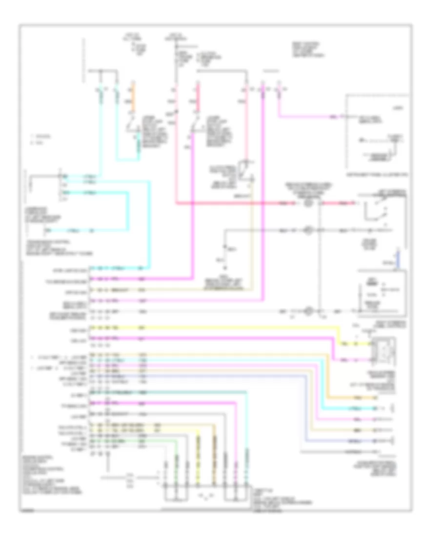
TRANSMISSION
2.2L VIN F
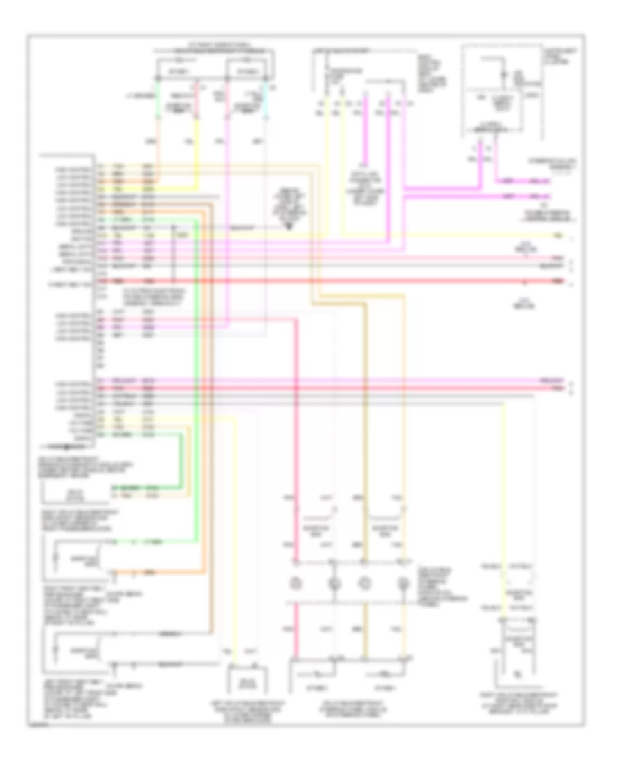
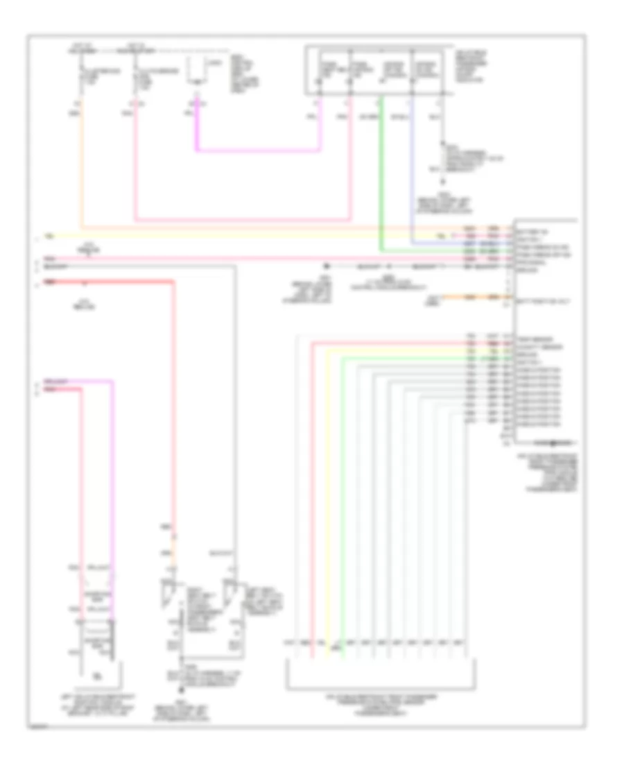
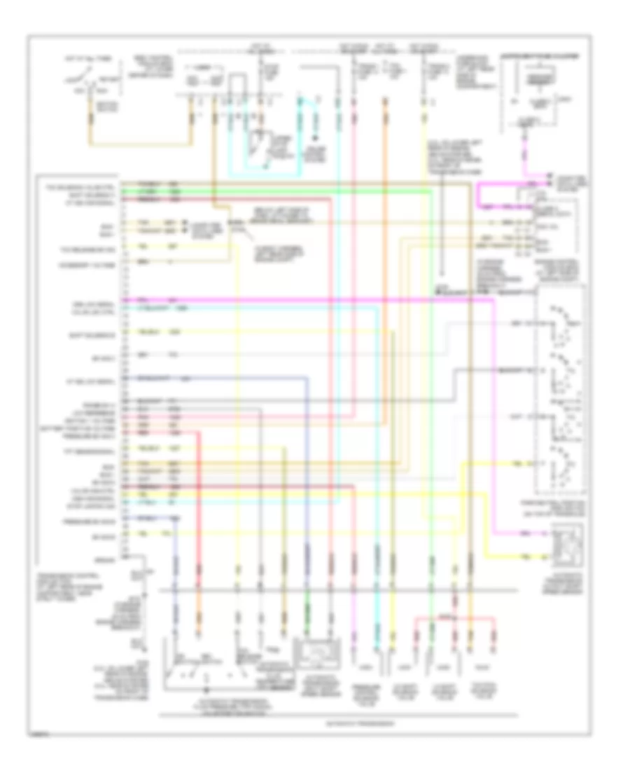
2.2L VIN F, A/T Wiring Diagram for Saturn Ion 2 2006
List of elements for 2.2L VIN F, A/T Wiring Diagram for Saturn Ion 2 2006:
- (2.2l: on lower left rear of engine, above starter) (2.4l: near starter on front of transmission case)
- (below left side of dash, attached to brake pedal bracket)
- (in body harness, left rear side of engine compt)
- (in engine harness, 35 cm from engine harness breakout) s175
- 1-2 shift solenoid valve
- 2-3 shift solenoid valve
- 2.4l 2.2l
- Acc
- Acc vol
- Accessory voltage
- At iss high signal
- At iss low signal
- Automatic transmission
- Automatic transmission fluid pressure (tfp) manual valve position switch
- Automatic transmission fluid temperature (tft) sensor
- Automatic transmission input shaft speed sensor
- Automatic transmission output shaft speed sensor
- Battery positive voltage
- Body control module (bcm) (at lower center of dash)
- Bus +
- Bus -
- Bus-
- Class 2 (ecm)
- Class 2 data
- Class 2 serial data
- Computer data lines system
- Cruise control system
- Dr switch
- E10
- Engine control module (ecm) (at left side of engine compt)
- G105
- G105 (2.2l: on lower left rear of engine, above starter) (2.4l: near starter on front of transmission case)
- Ground
- Hot at all times
- Hot in run or start
- Ignition 1 voltage
- Ignition switch
- Instrument panel cluster
- Lock
- Logic
- Low reference
- Message center
- Oss high signal
- Oss low signal
- Park/neutral position (pnp) switch (on top of transaxle)
- Pnk
- Pressure control solenoid valve
- Pressure sw sig b
- Pressure sw sig c
- Range sw a
- Red
- Rev switch
- Run
- S103
- S104
- S175 (in engine harness, 35 cm from engine harness breakout)
- Shift solenoid a
- Shift solenoid b
- Start
- Stop fuse 15a
- Stop lamp sw sig
- Sw sig b
- Sw sig c
- Sw sig d
- Tan
- Tcc pwm solenoid valve
- Tcc release sw sig
- Tcc release switch
- Tcc solenoid valve ctrl
- Tcm fuse 1 10a
- Tft sensor signal
- Trans 1 fuse 14 10a
- Trans 2 fuse 13 10a
- Transmission control module (tcm) (at left rear of engine compartment, near strut tower)
- Underhood fuse block (at left rear side of engine compartment)
- Upper stop lamp switch
- Valve high ctrl
- Valve low ctrl
TRUNK, TAILGATE, FUEL DOOR
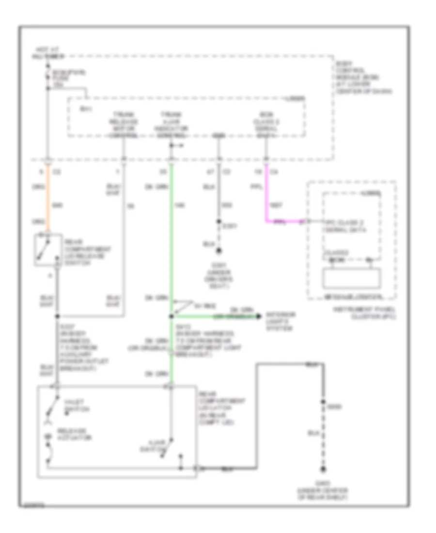
Trunk Release Wiring Diagram for Saturn Ion 2 2006
List of elements for Trunk Release Wiring Diagram for Saturn Ion 2 2006:
- Ajar switch
- B(+)
- Bcm (pwr) fuse 15a
- Bcm class 2 serial data
- Body control module (bcm) (at lower center of dash)
- Class2 (bcm)
- Compartment light breakout)
- G301 (under driver's seat)
- G403 (under center of rear shelf)
- Gnd
- Hot at all times
- Instrument panel cluster (ipc)
- Interior lights system
- Ipc class 2 serial data
- Logic
- Message center
- Rear compartment lid latch (in rear compt lid)
- Rear compartment lid release switch
- Release actuator
- S337 (in body harness, 7.5 cm from auxiliary power outlet breakout)
- S351
- S990
- Trunk ajar indicator control
- Trunk release motor control
- Valet switch
- W/ rke
WARNING SYSTEMS
Warning Systems Wiring Diagram for Saturn Ion 2 2006
List of elements for Warning Systems Wiring Diagram for Saturn Ion 2 2006:
- A11
- A14
- Acc
- Auto
- Body control module (bcm) (at lower center of dash)
- Chime
- Class 2 (sdm)
- Class 2 serial data
- Driver door jamb switch (behind left i/p access panel)
- Driver dr jamb sw sig
- Exterior lights system
- G201 (behind lower left side of dash, left of steering column)
- Head
- Hot at all times
- I/p/ign sw fuse 2a
- Ign
- Ignition switch
- Inflatable restraint sensing & diagnostic module (sdm) (under center console, behind emergency brake)
- Instrument panel cluster (ipc)
- Key-in switch
- Left seat belt switch (in left seat belt buckle assembly)
- Left turn sig lp pwr
- Logic
- Nca
- Off
- Park
- Park fuse 15a
- Park lamps pwr
- Right turn sig lp pwr
- Run
- S221
- S250
- Seat belt ind
- Seat belt switch
- Start
- Turn signal/ multi- function switch
WIPER/WASHER
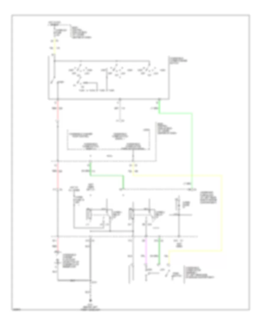
Wiper/Washer Wiring Diagram for Saturn Ion 2 2006
List of elements for Wiper/Washer Wiring Diagram for Saturn Ion 2 2006:
- (not used)
- A10 c3
- B11
- Body control module (bcm) (at lower center of dash)
- D10 c1
- D10 c2
- F10
- F11
- G101 (behind left front headlamp)
- High
- Hot at all times
- Hot in acc or run
- Int
- L10
- L11
- Logic
- Low
- M11
- Mist
- Off
- Park switch
- Q10
- Q11
- R11
- Red
- S101
- Underhood fuse block (at left rear side of engine compartment)
- Wash
- Windshield washer fluid pump (on bottom of washer fluid reservoir)
- Windshield washer pump control
- Windshield wiper motor assembly (at left rear side of engine compartment)
- Windshield wiper motor park switch signal
- Windshield wiper switch signal 1
- Windshield wiper switch signal 2
- Windshield wiper/washer switch
- Wiper 1 relay
- Wiper 2 relay
- Wiper diode
- Wiper fuse 19 25a
- Wiper sw fuse 10a
- X10