AIR CONDITIONING
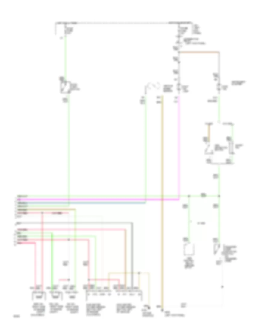
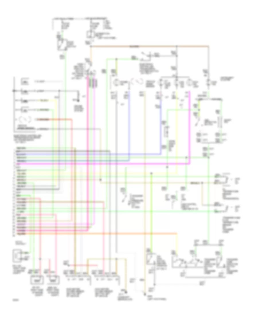
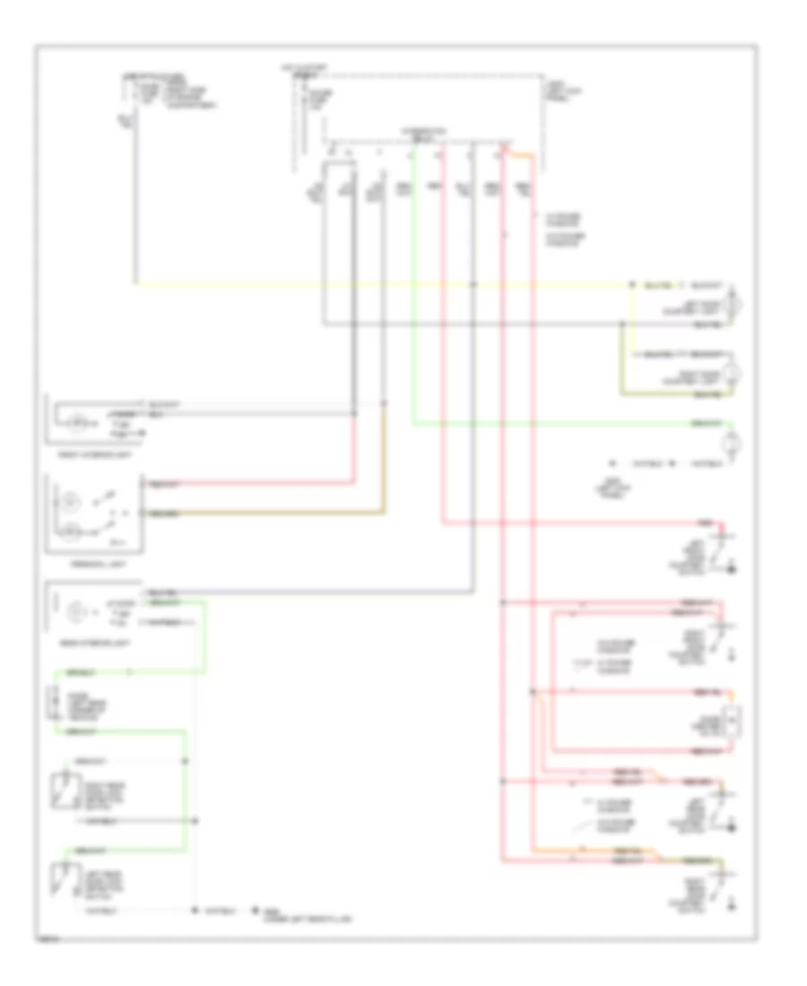
A/C Wiring Diagram for Toyota 4Runner SR5 1994

List of elements for A/C Wiring Diagram for Toyota 4Runner SR5 1994:
- (2.4l)
- (3.0l)
- 3.0l a/t w/ 4wd
- 3.0l only
- A/c
- A/c amplifier (right side of i/p)
- A/c condenser fan motor (front of engine compt)
- A/c condenser fan relay no. 1
- A/c condenser fan relay no. 2
- A/c cut relay (right side of i/p)
- A/c dual pressure switch (right side of i/p)
- A/c fuse 10a
- A/c idle- up valve (right rear of engine compt)
- A/c magnetic clutch (right front of engine compt)
- A/c single pressure switch (right side of i/p)
- A/c switch
- A/c thermistor (right side of i/p)
- A24
- Act
- Acv
- All others
- B10
- B19
- B6 a4
- Blower motor (right side of i/p)
- Blower resistor (right side of i/p)
- Blower switch
- Cds fan fusible link 30a
- Engine control module (right side of i/p)
- Engine controls system (efi main relay)
- Front heater relay
- G108 (left side of radiator)
- G200 (left kick panel)
- Gauge fuse 10a
- Heater fuse 40a
- Hot at all times
- Hot in on or start
- Igniter (left side of engine compt)
- Integration relay
- Interior lights system (rheostat)
- Interior lights system (tail fuse)
- J/b 1 (left kick panel)
- Off
- Pnk
- R/b 3 (right kick panel)
- R/b 3 (right side of glove box)
- R/b 4 (right side of engine compt)
- Red
- Resistor (front of engine compt)
- Water temperature switch (center rear of engine compt)
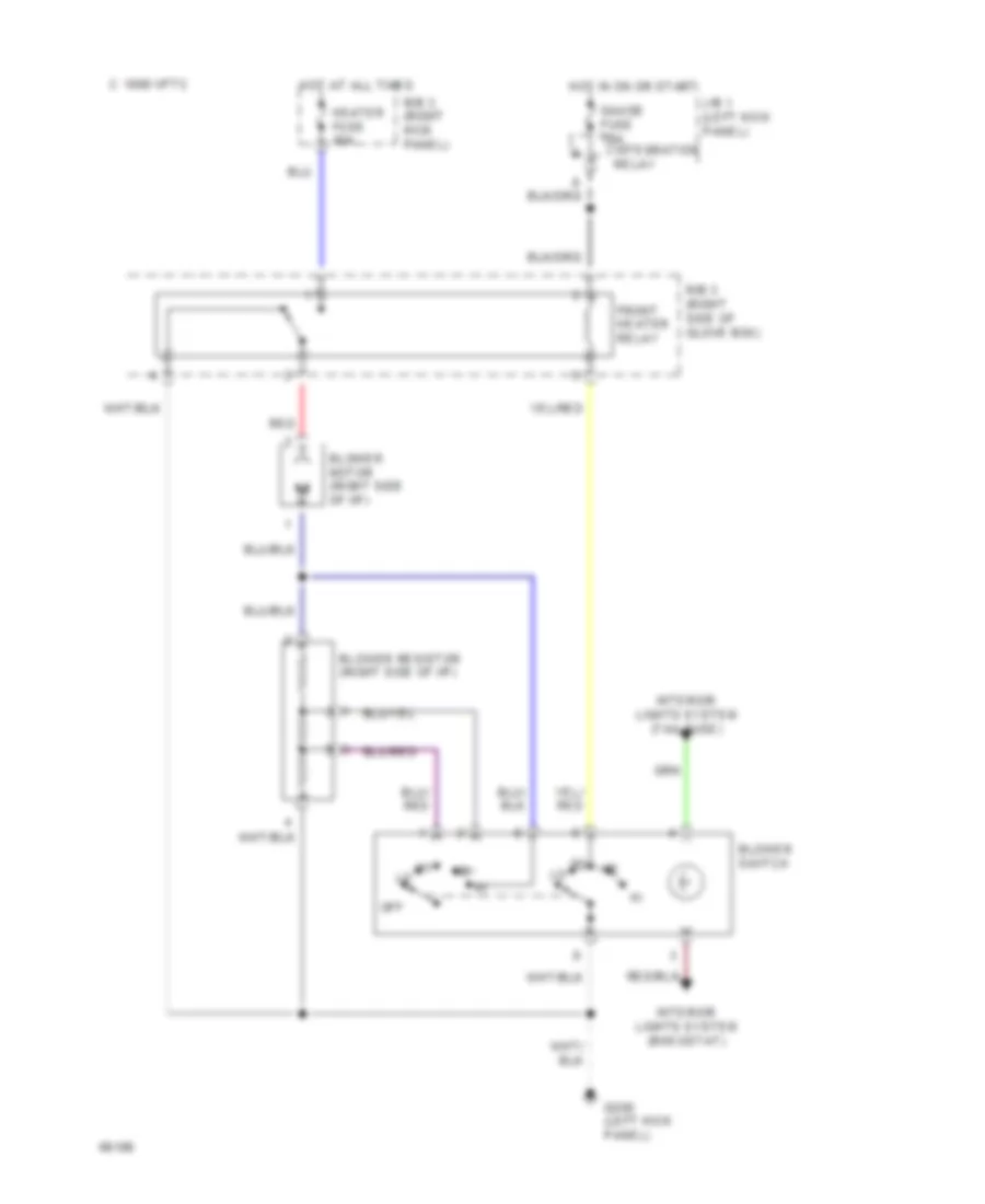
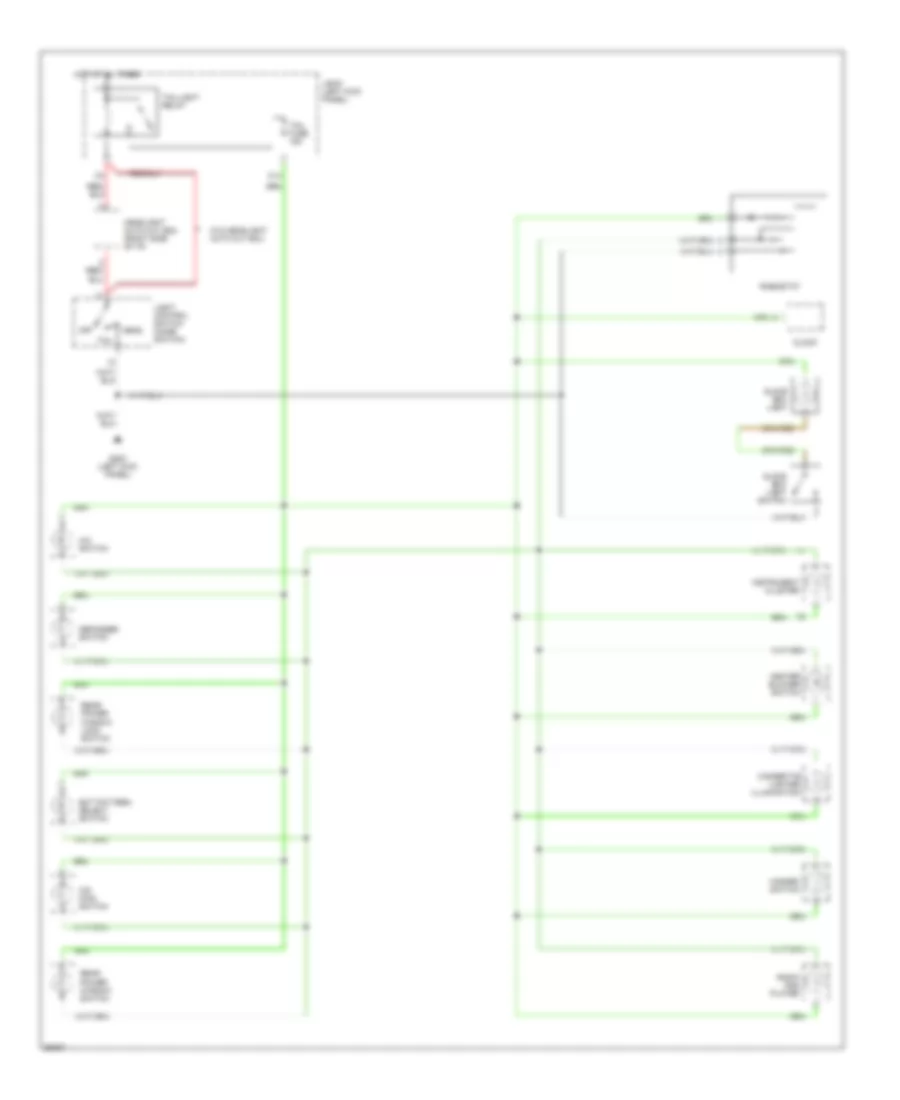
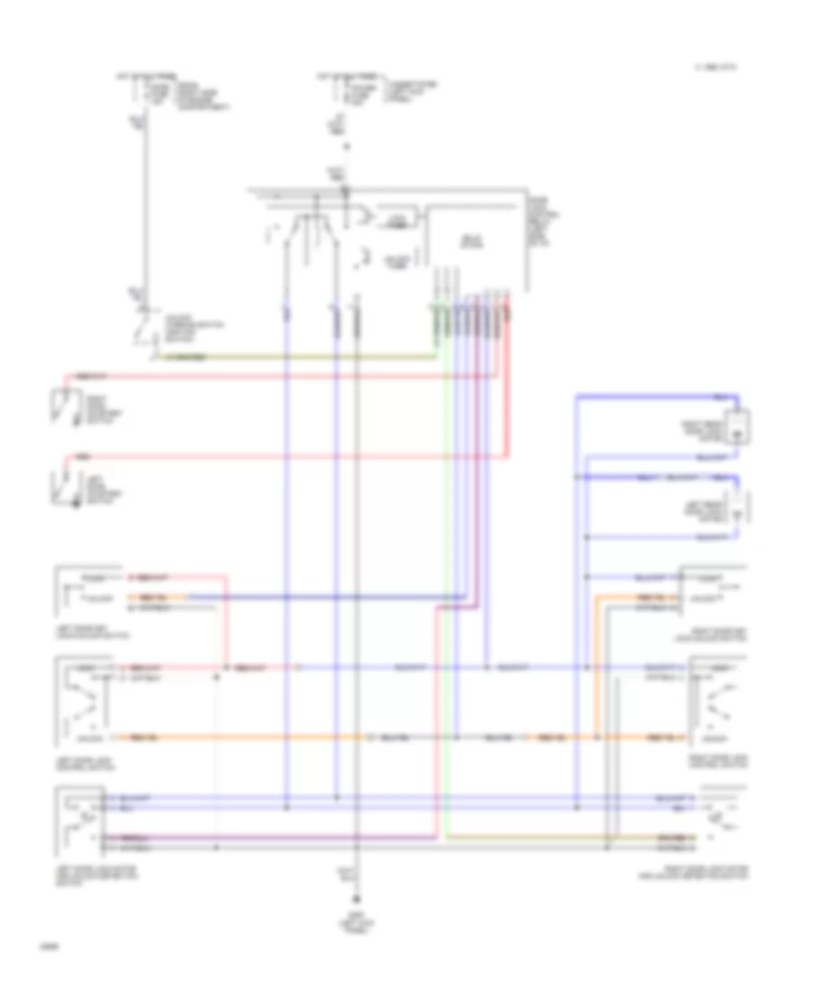
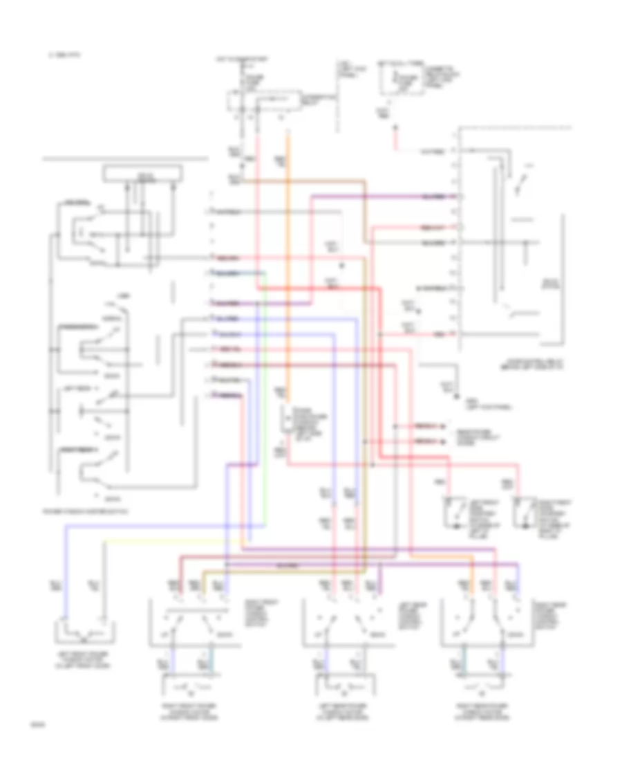
Heater Wiring Diagram for Toyota 4Runner SR5 1994
List of elements for Heater Wiring Diagram for Toyota 4Runner SR5 1994:
- Blower motor (right side of i/p)
- Blower resistor (right side of i/p)
- Blower switch
- C 1995 vftc
- Front heater relay
- G200 (left kick panel)
- Gauge fuse 10a
- Heater fuse 40a
- Hot at all times
- Hot in on or start
- Integration relay
- Interior lights system (rheostat)
- Interior lights system (tail fuse)
- J/b 1 (left kick panel)
- Off
- R/b 3 (right kick panel)
- R/b 3 (right side of glove box)
- Red
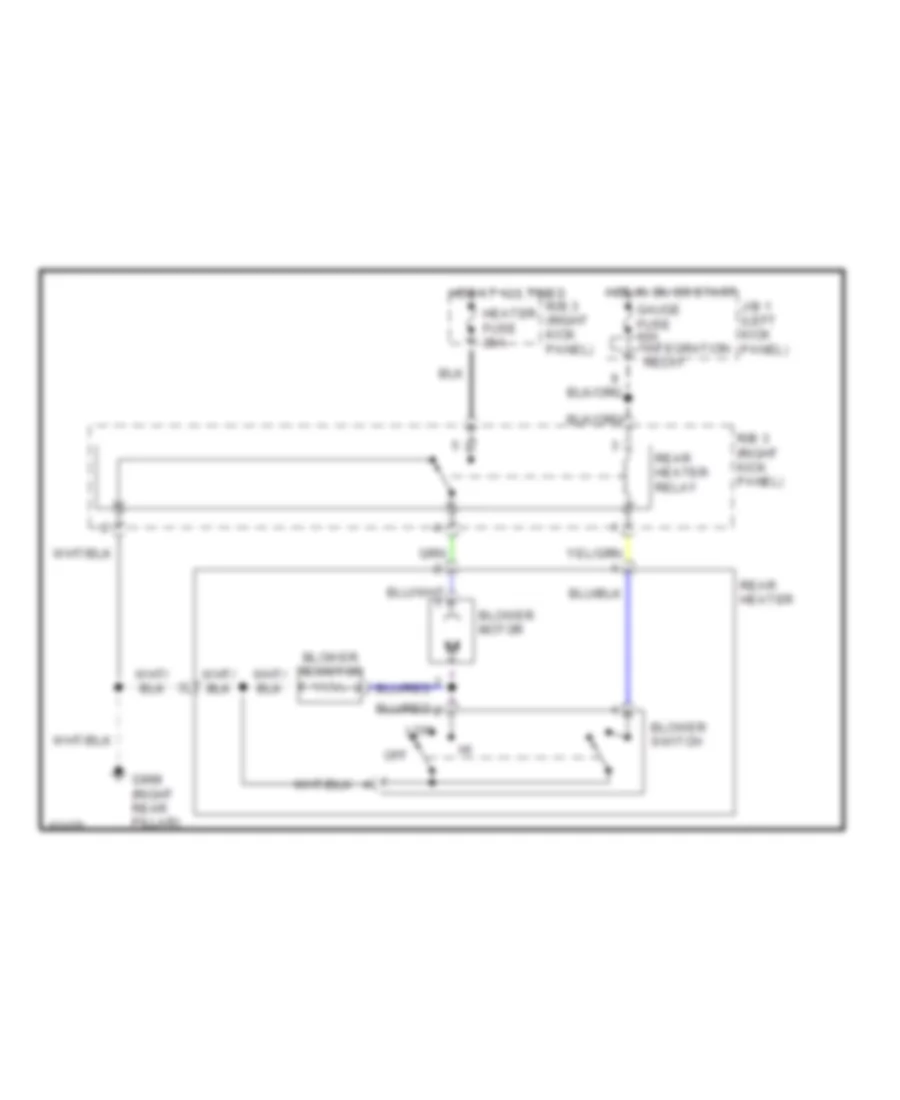
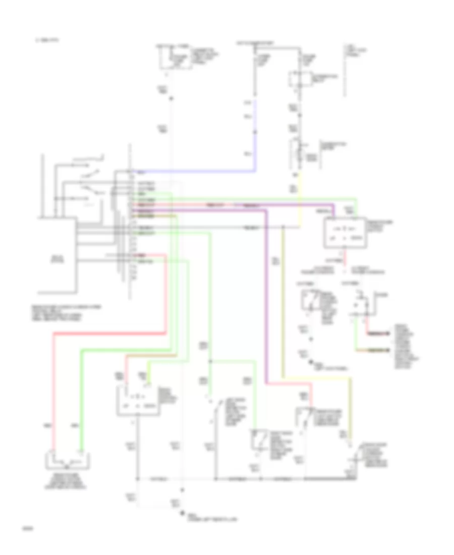
Rear Heater Wiring Diagram for Toyota 4Runner SR5 1994
List of elements for Rear Heater Wiring Diagram for Toyota 4Runner SR5 1994:
- Blower motor
- Blower resistor
- Blower switch
- G998 (right rear pillar)
- Gauge fuse 10a integration relay
- Heater fuse 20a
- Hot at all times
- Hot in on or start
- J/b 1 (left kick panel)
- Low
- Off
- R/b 3 (right kick panel)
- Rear heater
- Rear heater relay
ANTI-LOCK BRAKES
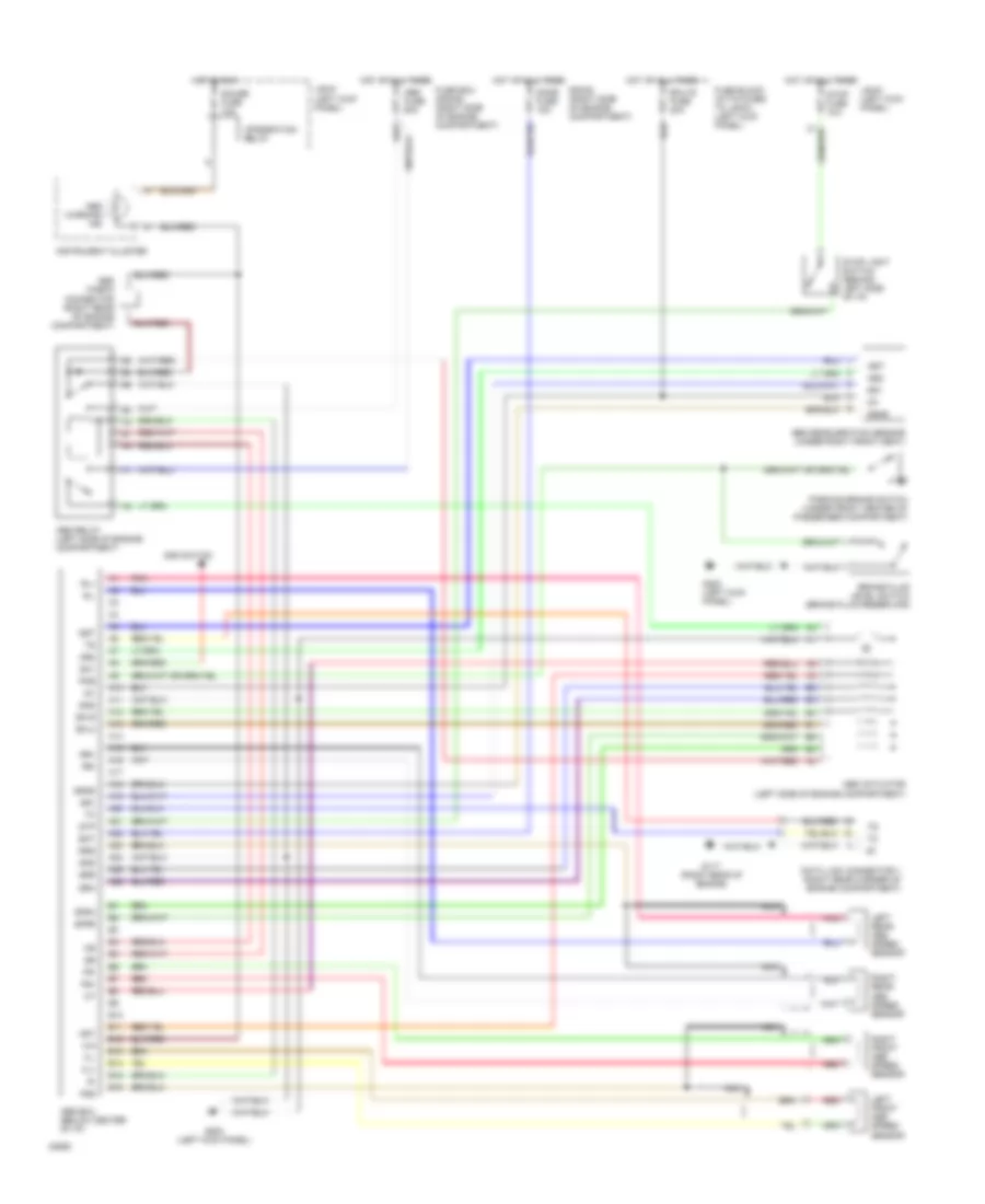
All-Wheel ABS Wiring Diagram for Toyota 4Runner SR5 1994
List of elements for All-Wheel ABS Wiring Diagram for Toyota 4Runner SR5 1994:
- A10
- A11
- A12
- A13
- A14
- A15
- A16
- A17
- A18
- A19
- A20
- A21
- A22
- A23
- A24
- A25
- A26
- Abs actuator (left side of engine compartment)
- Abs check connector (right rear of engine compartment)
- Abs deceleration sensor (under right front seat)
- Abs ecu (below center of i/p)
- Abs fuse 60a
- Abs relay (left side of engine compartment)
- Abs warning ind
- Add switch
- Ast
- B10
- B11
- B12
- B13
- B14
- B15
- B16
- Bat
- Brake fluid level switch (brake fluid reservoir)
- Data link connector 1 (right rear corner of engine compartment)
- Dome fuse 15a
- Ecu-ig fuse 20a
- Ex1
- Fl+
- Fl-
- Fr+
- Fr-
- Fss
- Fuse block (attatched to j/b #1) (left kick panel)
- Fuse box (r/b #2) (right side of engine compartment)
- G117 (right rear of engine)
- G200 (left kick panel)
- Gauge fuse 10a
- Ggnd
- Gnd
- Gs1
- Gs2
- Gst
- Hot at all times
- Hot in run
- Ig1
- Instrument cluster
- Integration relay
- J/b #1 (left kick panel)
- Left front abs speed sensor
- Left rear abs speed sensor
- Nca
- Parking brake switch (under front center of passenger compartment)
- Pkb
- Pnk
- R/b #2 (right side of engine compartment)
- Red
- Right front abs speed sensor
- Right rear abs speed sensor
- Rl+
- Rl-
- Rr+
- Rr-
- Rss
- Sflh
- Sflr
- Sfrh
- Sfrr
- Srh
- Srr
- Stop fuse 15a
- Stop light switch (behind left side of i/p)
- Stp
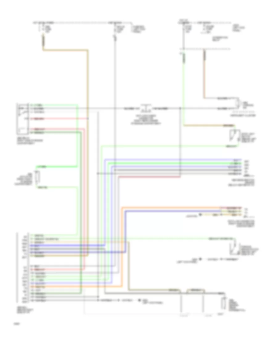
Rear ABS Wiring Diagram for Toyota 4Runner SR5 1994
List of elements for Rear ABS Wiring Diagram for Toyota 4Runner SR5 1994:
- Abs actuator (front right of engine compartment)
- Abs deceleration sensor (below center of i/p)
- Abs ecu (behind right side of i/p)
- Abs fuse 15a
- Abs relay (right side of engine compartment)
- Abs speed sensor (rear differential)
- Abs warning ind
- Anti-lock check connector (right rear corner of engine compartment)
- Bat
- Data link connector (right side of engine compartment)
- Ecu-ig fuse 20a
- Fuse box (left kick panel)
- G200 (left kick panel)
- Gauge fuse 10a
- Gnd
- Gs1
- Gs2
- Gst
- Hot at all times
- Hot in run
- Ig1
- Instrument cluster
- Integration relay
- J/b #1 (left kick panel)
- Location
- Parking brake switch (behind left side of i/p)
- Pkb
- Rr+
- Rr-
- Rss
- Stop fuse 15a
- Stop light switch (behind left side of i/p)
- Stp
COMPUTER DATA LINES
2.4L
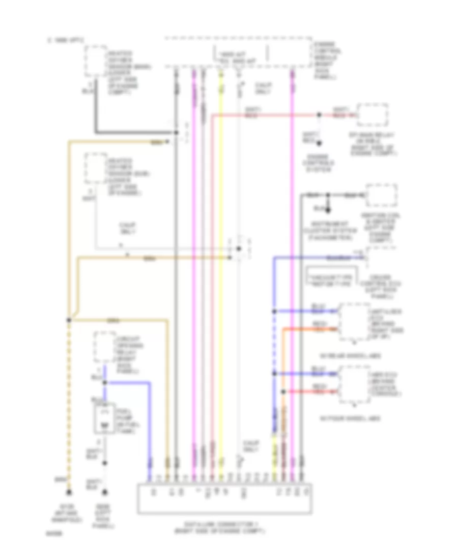
2.4L, Data Link Connector Wiring Diagram for Toyota 4Runner SR5 1994
List of elements for 2.4L, Data Link Connector Wiring Diagram for Toyota 4Runner SR5 1994:
- & igniter (left side
- (in r/b-2,
- (intake
- (left kick
- (left kick panel)
- (right side of engine compt)
- **ex. 4wd a/t
- *4wd a/t
- *vacuum type **motor type
- 1995 vftc c
- Abs ecu (behind center console)
- Anti-lock ecu (behind right side of i/p)
- Calif. only
- Circuit opening relay (right kick panel)
- Control ecu
- Cruise
- Data link connector 1
- Efi main relay
- Engine compt)
- Engine control module (right kick panel)
- Engine controls system
- Fuel pump (in fuel tank)
- G120
- G200
- Heated oxygen sensor (main) (lower left side of engine compt)
- Heated oxygen sensor (sub) (lower left side of engine)
- Ig-
- Ignition coil
- Instrument cluster system (tachometer)
- Manifold)
- Ox2
- Panel)
- Right side of engine compt)
- Te2
- W/ four wheel abs
- W/ rear wheel abs
3.0L
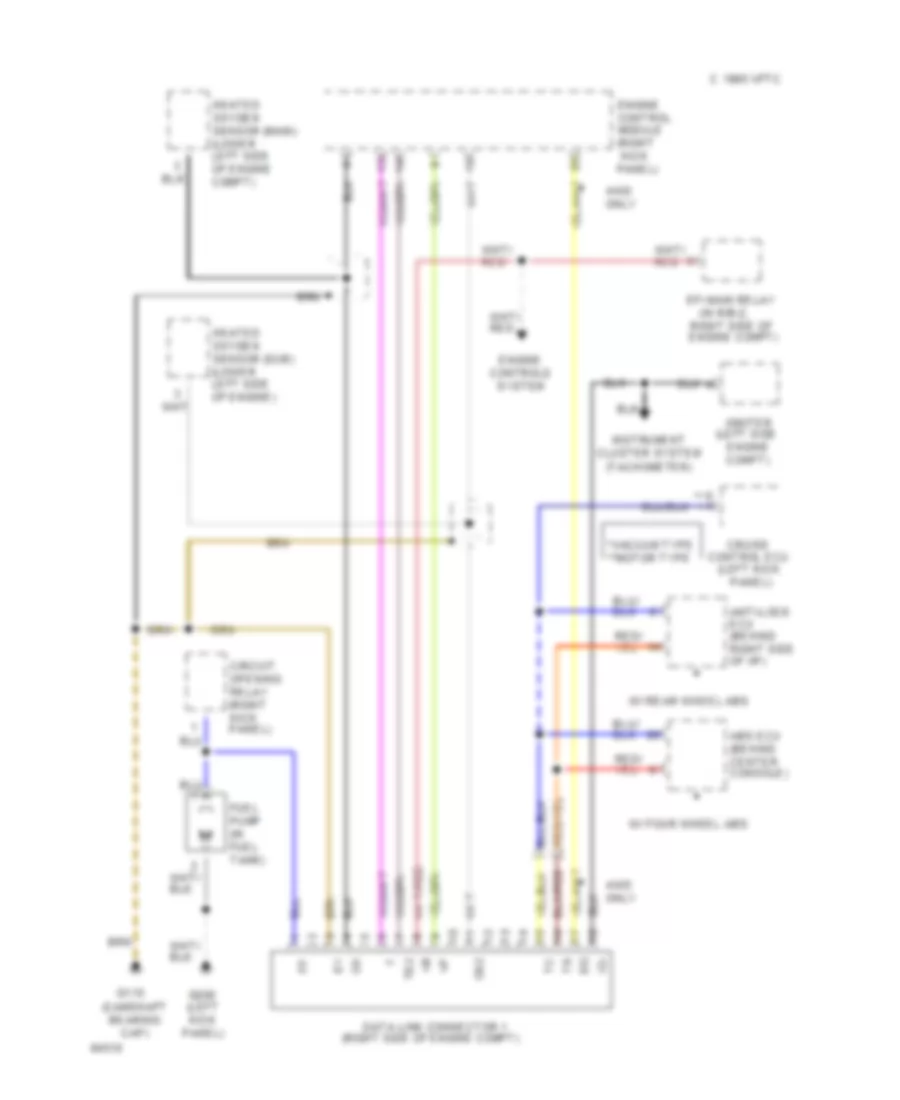
3.0L, Data Link Connector Wiring Diagram for Toyota 4Runner SR5 1994
List of elements for 3.0L, Data Link Connector Wiring Diagram for Toyota 4Runner SR5 1994:
- (camshaft bearing cap)
- (in r/b-2,
- (left kick
- (left kick panel)
- (left side
- (right side of engine compt)
- *vacuum type **motor type
- 1995 vftc c
- 4wd only
- Abs ecu (behind center console)
- Anti-lock ecu (behind right side of i/p)
- Circuit opening relay (right kick panel)
- Control ecu
- Cruise
- Data link connector 1
- Efi main relay
- Engine compt)
- Engine control module (right kick panel)
- Engine controls system
- Fuel pump (in fuel tank)
- G115
- G200
- Heated oxygen sensor (main) (lower left side of engine compt)
- Heated oxygen sensor (sub) (lower left side of engine)
- Ig-
- Igniter
- Instrument cluster system (tachometer)
- Ox2
- Panel)
- Right side of engine compt)
- Te2
- W/ four wheel abs
- W/ rear wheel abs
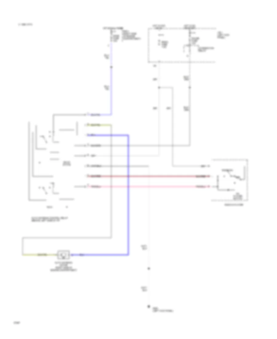
CRUISE CONTROL
Cruise Control Wiring Diagram, Motor Type for Toyota 4Runner SR5 1994
List of elements for Cruise Control Wiring Diagram, Motor Type for Toyota 4Runner SR5 1994:
- 1995 vftc c
- A/t
- Batt
- C13
- Cancel
- Ccs
- Cms
- Cruise control actuator (left side of engine compartment)
- Cruise control clutch switch (left side of i/p)
- Cruise control ecu (left side of i/p)
- Cruise control ind
- Cruise control main switch (combination switch)
- Data link connector no. 1 (right side of engine compartment)
- Dome fuse 15a
- Ect
- Engine control system (engine control ecu)
- Engine fuse 10a
- G200 (left kick panel)
- Gauge fuse 10a
- Gnd
- Hot at all times
- Hot in run and start
- Idl
- Igb
- Instrument cluster
- Instrument cluster system (brake fluid level switch)
- Integration relay
- J/b #1 (left kick panel)
- M/t
- N&c
- Parking brake switch (center console)
- Pkb
- R/b #2 (right side of engine compartment)
- Resume/ accel
- Set/ coast
- Spd
- Starting/charging system (park/neutral position switch)
- Stop fuse 15a
- Stop light switch (left side of i/p)
- Stp+
- Stp-
- Transmission system (engine and electronic controlled transmission)
- Vr1
- Vr2
- Vr3
- Vss output
Cruise Control Wiring Diagram, Vacuum Type for Toyota 4Runner SR5 1994
List of elements for Cruise Control Wiring Diagram, Vacuum Type for Toyota 4Runner SR5 1994:
- 1995 vftc c
- A/t
- Act
- C13
- Cancel
- Ccs
- Cruise control actuator (left rear corner of engine compartment)
- Cruise control clutch switch (left side of i/p)
- Cruise control ecu (left side of i/p)
- Cruise control ind
- Cruise control main relay (left side of i/p)
- Cruise control main switch (combination switch)
- Cruise control vacuum pump (left side of engine compartment)
- Cruise control vacuum switch (left side of engine compartment)
- Data link connector no. 1 (right side of engine compartment)
- Ect
- Engine fuse 10a
- G200 (left kick panel)
- Gauge fuse 10a
- Hot at all times
- Hot in run and start
- Igb
- Igc
- Instrument cluster
- Integration relay
- J/b #1 (left kick panel)
- M/t
- N&c
- O/d
- Parking brake switch (left side of i/p)
- Pkb
- Red
- Resume/ accel
- Set/ coast
- Spd
- Starting/charging system (park/neutral position switch)
- Stop fuse 15a
- Stop light switch (left side of i/p)
- Stp+
- Stp-
- Transmission system (engine and electronic controlled transmission)
- Transmission system (engine and electronic controlled transmission) (w/ ect) (o/d relay) (w/o ect)
- Vac
- Vss output
DEFOGGERS
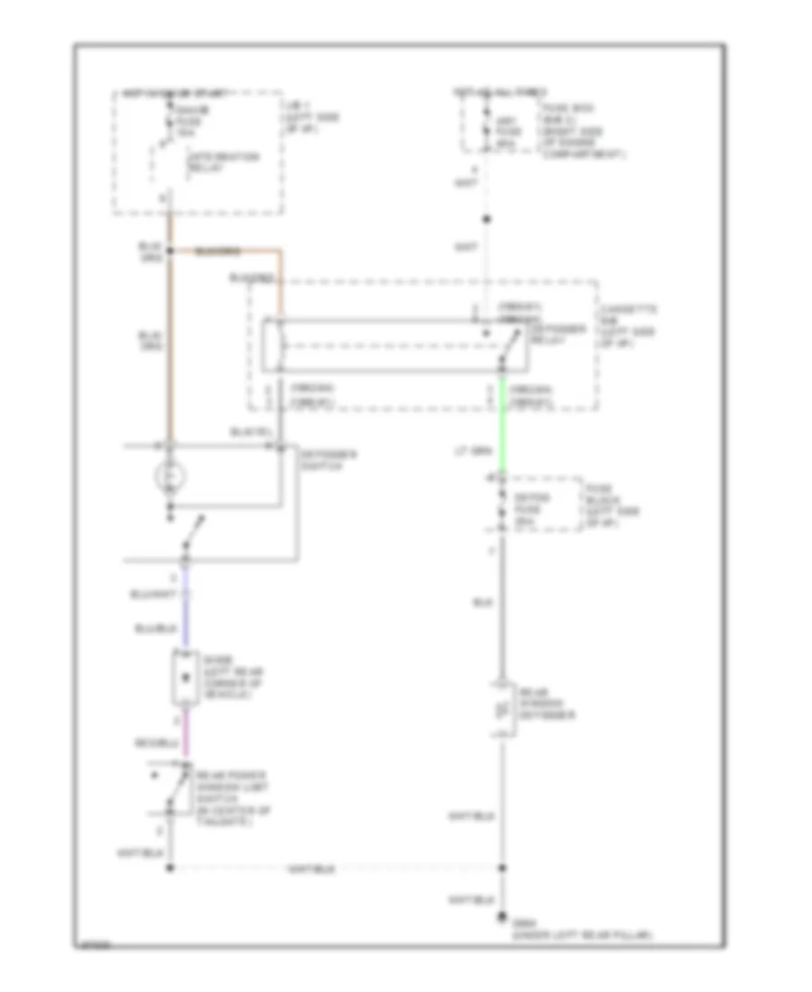
Defogger Wiring Diagram for Toyota 4Runner SR5 1994
List of elements for Defogger Wiring Diagram for Toyota 4Runner SR5 1994:
- (1990-91)
- (1990-91) (1992-94)
- (1992-94)
- Am1 fuse 40a
- Cassette r/b (left side of i/p)
- Defog fuse 20a
- Defogger relay
- Defogger switch
- Diode (left rear corner of vehicle)
- Fuse block (left side of i/p)
- Fuse box (r/b 2) (right side of engine compartment)
- G904 (under left rear pillar)
- Gauge fuse 10a
- Hot at all times
- Hot in on or start
- Integration relay
- J/b 1 (left side of i/p)
- Rear power window limit switch (in center of tailgate)
- Rear window defogger
ENGINE PERFORMANCE
2.4L
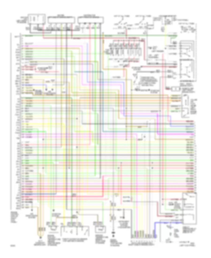
2.4L, Engine Performance Wiring Diagrams, A/T with 4-Wheel Drive (1 of 2) for Toyota 4Runner SR5 1994
List of elements for 2.4L, Engine Performance Wiring Diagrams, A/T with 4-Wheel Drive (1 of 2) for Toyota 4Runner SR5 1994:
- #10
- #20
- (left
- (left kick panel)
- (right
- (right side of engine compt)
- (right side of engine)
- (tachometer)
- +b1
- 4wd
- A3 j/b 1 kick panel)
- Acc
- Alt fuse 100a
- Batt
- Circuit opening relay (behind right side of i/p)
- Cluster system
- Coil wire
- Cruise control system
- Data link connector 1
- Distributor
- E21
- Efi fuse 15a
- Efi main relay
- Egr
- Egr gas temperature sensor (right rear of engine)
- Engine control module (right kick panel)
- Engine coolant temperature sensor (right front of engine)
- Eo1
- Eo2
- Fpu
- Fuel injectors
- Fuel pump (in fuel tank)
- G100 (left fender)
- G120 (intake manifold)
- G200
- Hot at all times
- Hot in on or start
- Ht1
- Ht2
- Idl
- Ig2
- Igf
- Ign fuse 7.5a
- Igniter
- Ignition coil and igniter (left side of engine compt)
- Ignition switch
- Igt
- Instrument
- J/b 1 (left kick panel)
- Knk
- Knock sensor (right side of engine)
- Lock
- Noise filter (left side engine compt)
- Od1
- Od2
- Ox1
- Ox2
- Park/neutral position switch (on transmission) (closed in park and neutral)
- Pnk
- Pwr
- R/b 2 engine compt)
- Red
- Sp1
- Sp2
- St1
- Sta
- Start
- Starter relay
- Starting
- Starting system
- Stj
- Stp
- System
- Te2
- Tha
- Thg
- Throttle position sensor
- Thw
- Vcc
- Volume air flow meter (left front engine compt)
- Vta
2.4L, Engine Performance Wiring Diagrams, A/T with 4-Wheel Drive (2 of 2) for Toyota 4Runner SR5 1994
List of elements for 2.4L, Engine Performance Wiring Diagrams, A/T with 4-Wheel Drive (2 of 2) for Toyota 4Runner SR5 1994:
- (california)
- (center of i/p)
- (intake manifold)
- (left kick panel)
- (on trans- mission)
- (right
- (right side
- 4wd
- 4wd ind.
- A/t fluid temp. ind.
- Add
- Add detection switch
- As vsv
- B10
- B12
- Compt)
- Control
- Cruise control system
- D12
- Diode
- Egr vsv
- Electronic controlled transmission pattern switch
- Electronic controlled transmission solenoid (on transmission)
- Fpu vsv
- G120
- G200
- Gauge fuse 10a
- Hot at all times
- Hot in on or start
- Ht1
- Ht2
- Instrument cluster
- Integration relay
- J/b 1 (left kick panel)
- Main heated oxygen sensor (bottom left of vehicle)
- Malf. ind. lamp
- O/d main switch (center console)
- O/d off ind.
- Of engine
- Of engine compt)
- Of i/p)
- Oil
- Oxl1
- Oxr1
- Park/ neutral position switch n
- Pnk
- Power ind.
- Pressure switch
- Red
- Relay
- Short pin
- Side
- Stop fuse 15a
- Stop light switch
- Sub heated oxygen sensor (bottom left of engine) (california)
- Switch
- Temperature
- Transfer
- Transfer case indicator switch (on transfer case)
- Vehicle speed sensor
- W/ add
- W/o add
2.4L, Engine Performance Wiring Diagrams, Except A/T with 4-Wheel Drive (1 of 2) for Toyota 4Runner SR5 1994
List of elements for 2.4L, Engine Performance Wiring Diagrams, Except A/T with 4-Wheel Drive (1 of 2) for Toyota 4Runner SR5 1994:
- #10
- #20
- (intake
- (left
- (left kick panel)
- (right
- (right side of engine compt)
- (right side of engine)
- (tachometer)
- +b1
- 4wd
- A3 j/b 1 kick panel)
- Acc
- Alt fuse 80a
- Batt
- Circuit opening relay (behind right side of i/p)
- Cluster system
- Coil wire
- Distributor
- E21
- Efi fuse 15a
- Efi main relay
- Egr
- Egr gas temperature sensor (right rear of engine)
- Engine control module (right kick panel)
- Engine coolant temperature sensor (right front of engine)
- Eo1
- Eo2
- Fpu
- Fuel injectors
- Fuel pump (in fuel tank)
- G100 (left fender)
- G120
- G200
- Hot at all times
- Hot in on or start
- Ht1
- Ht2
- Idl
- Ig2
- Igf
- Ign fuse 7.5a
- Igniter
- Ignition coil and igniter (left side of engine compt)
- Ignition switch
- Igt
- Instrument
- J/b 1 (left kick panel)
- Knk
- Knock sensor (right side of engine)
- Lock
- Manifold)
- Noise filter (left side engine compt)
- Nsw
- Ox1
- Ox2
- Pnk
- R/b 2 engine compt)
- Red
- Spd
- St1
- Sta
- Start
- Starter relay
- Starting
- Starting system
- Stj
- Stp
- System
- Te2
- Tha
- Thg
- Throttle position sensor
- Thw
- Vcc
- Volume air flow meter (left front engine compt)
- Vta
2.4L, Engine Performance Wiring Diagrams, Except A/T with 4-Wheel Drive (2 of 2) for Toyota 4Runner SR5 1994
List of elements for 2.4L, Engine Performance Wiring Diagrams, Except A/T with 4-Wheel Drive (2 of 2) for Toyota 4Runner SR5 1994:
- (california)
- (center of i/p)
- (intake manifold)
- (left kick panel)
- (right side
- 4wd ind.
- Add
- Add detection switch
- As vsv
- B12
- Compt)
- Control
- D12
- Egr vsv
- Fpu vsv
- G120
- G200
- Gauge fuse 10a
- Hot at all times
- Hot in on or start
- Ht1
- Ht2
- Instrument cluster
- Integration relay
- J/b 1 (left kick panel)
- Main heated oxygen sensor (bottom left of vehicle)
- Malf. ind. lamp
- Of engine
- Of engine compt)
- Oxl1
- Oxr1
- Pnk
- Red
- Relay
- Short pin
- Stop fuse 15a
- Stop light switch
- Sub heated oxygen sensor (bottom left of engine) (california)
- Transfer case indicator switch (on transfer case)
- Vehicle speed sensor
- W/ add
- W/o add
3.0L
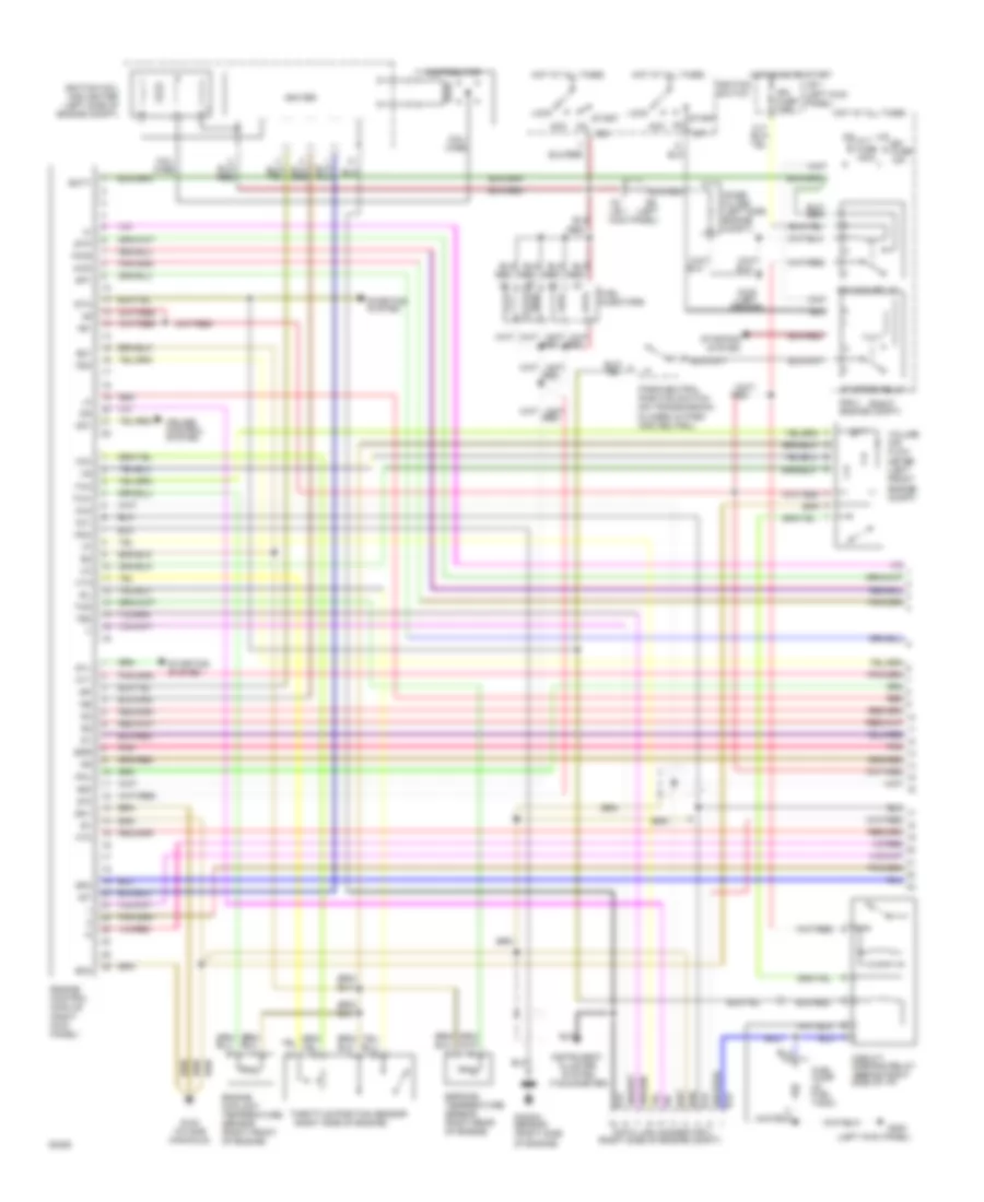
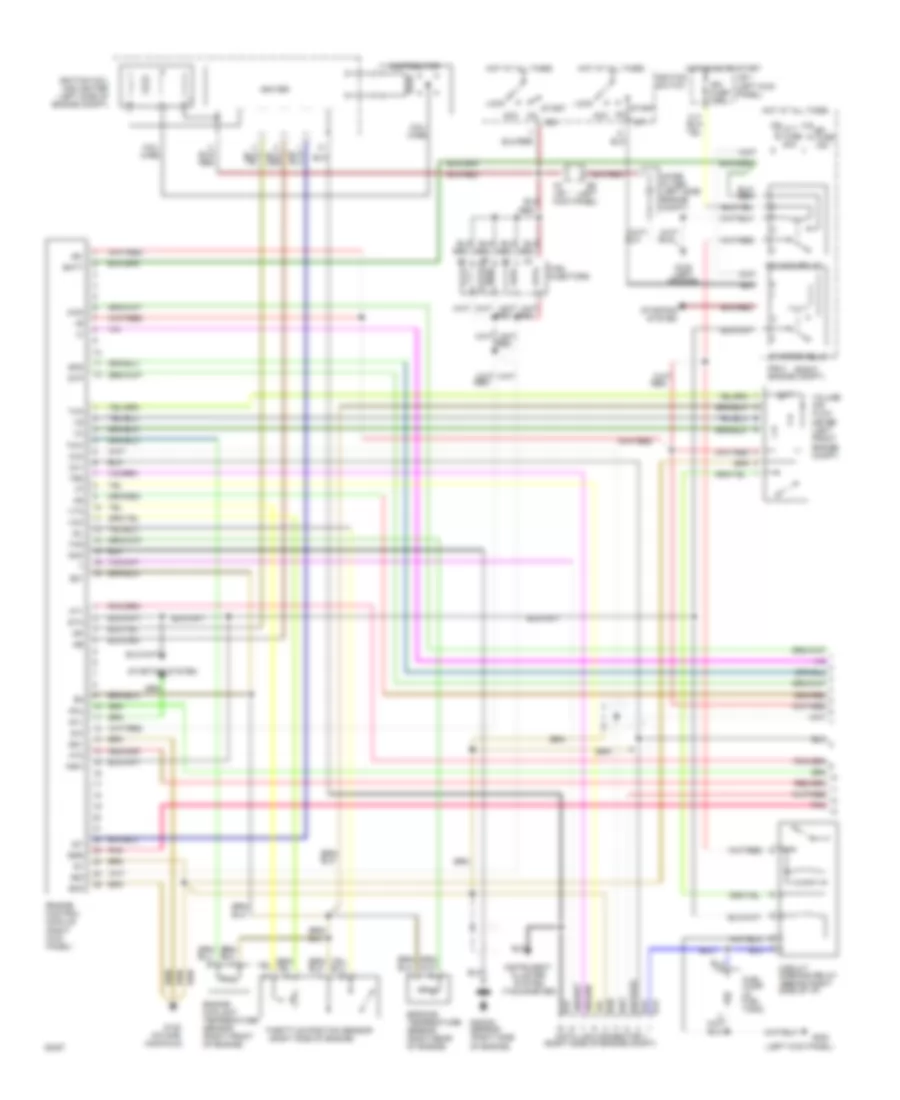
3.0L, Engine Performance Wiring Diagrams (1 of 2) for Toyota 4Runner SR5 1994
List of elements for 3.0L, Engine Performance Wiring Diagrams (1 of 2) for Toyota 4Runner SR5 1994:
- conditioning
- #10
- #20
- (camshaft
- (left
- (left fender)
- (left front of engine)
- (left kick panel)
- (left side of engine compt)
- (right
- (right side of engine compt)
- (tachometer)
- +b1
- 2wd
- 4wd
- A/c
- A/t
- Acc
- Act
- Acv
- Air
- Air condit- ioning system
- Alt fuse 80a
- Batt
- Bearing cap)
- Circuit opening relay (behind right side of i/p)
- Cluster system
- Coil
- Coil wire
- Conditioning
- Cruise control system
- Data link connector 1
- Distributor
- E21
- Efi fuse 15a
- Efi main relay
- Egr
- Egr gas temperature sensor (right side of engine)
- Engine control module (right kick panel)
- Engine coolant temperature sensor (center rear of engine)
- Eo1
- Eo2
- Fpu
- Fuel
- Fuel pump (in fuel tank)
- G100
- G117
- G200
- Hot at all times
- Hot in on or start
- Ht1
- Ht2
- Idl
- Ig-
- Ig2
- Igf
- Ign fuse 7.5a
- Igniter
- Ignition
- Ignition switch
- Igt
- Injec-
- Instrument
- J/b 1
- J/b 1 (left kick panel)
- Kick panel)
- Knk
- Knock sensor (top center of engine)
- Lock
- M/t
- Noise filter (left front engine compt)
- Od1
- Od2
- Oil
- Ox1
- Ox2
- Park/neutral position switch (on transmission) (closed in park and neutral)
- Pnk
- Pwr
- R/b 2 engine compt)
- Red
- Sel1
- Sel2
- Sp1
- Sp2
- St1
- Sta
- Start
- Starter relay
- Starting
- Starting system
- Stj
- Stp
- System
- Te2
- Tha
- Thg
- Tho1
- Tho2
- Throttle position sensor (top center of engine)
- Thw
- Tors
- Volume air flow meter (left front engine compt)
- Vta
- Wire
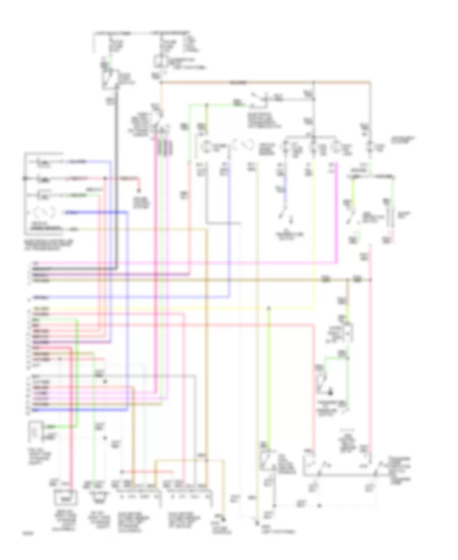
3.0L, Engine Performance Wiring Diagrams (2 of 2) for Toyota 4Runner SR5 1994
List of elements for 3.0L, Engine Performance Wiring Diagrams (2 of 2) for Toyota 4Runner SR5 1994:
- (a/t only)
- (a/t)
- (camshaft bearing cap)
- (left kick panel)
- (m/t)
- (on trans- mission)
- (right side
- (right side of i/p)
- 4wd ind.
- 4wd w/ a/t
- 4wd w/ m/t
- A/t
- A/t fluid temp. ind.
- A/t w/ 4wd only
- A/t w/ add
- Add control relay (center of i/p)
- Add detection switch
- As vsv
- B10
- B12
- Compt)
- Cruise control system
- D12
- Diode
- Egr vsv
- Electronic controlled transmission pattern switch (a/t only)
- Electronic controlled transmission solenoid (on transmission)
- Fpu vsv
- G117
- G200
- Gauge fuse 10a
- Hot at all times
- Hot in on or start
- Ht1
- Instrument cluster
- Integration relay
- J/b 1 (left kick panel)
- M/t w/ add
- Main heated oxygen sensor (bottom left of vehicle)
- Malf. ind. lamp
- O/d main switch (center console)
- O/d off ind.
- Of engine
- Of engine compt)
- Oil temperature sensor (on transmission)
- Oxl1
- Oxr
- Park/ neutral position switch n
- Pnk
- Power ind.
- Red
- Short pin
- Stop fuse 15a
- Stop light switch
- Sub heated oxygen sensor (bottom left of vehicle)
- Transfer case fluid temperature sensor (on transfer case)
- Transfer case indicator switch (on transfer case)
- Transfer oil pressure switch (a/t w/ add)
- Vehicle speed sensor
- W/ add
- W/o add
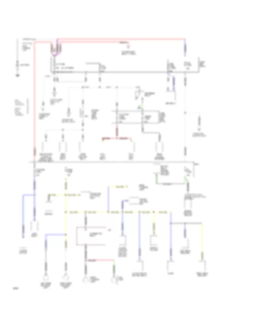
EXTERIOR LIGHTS
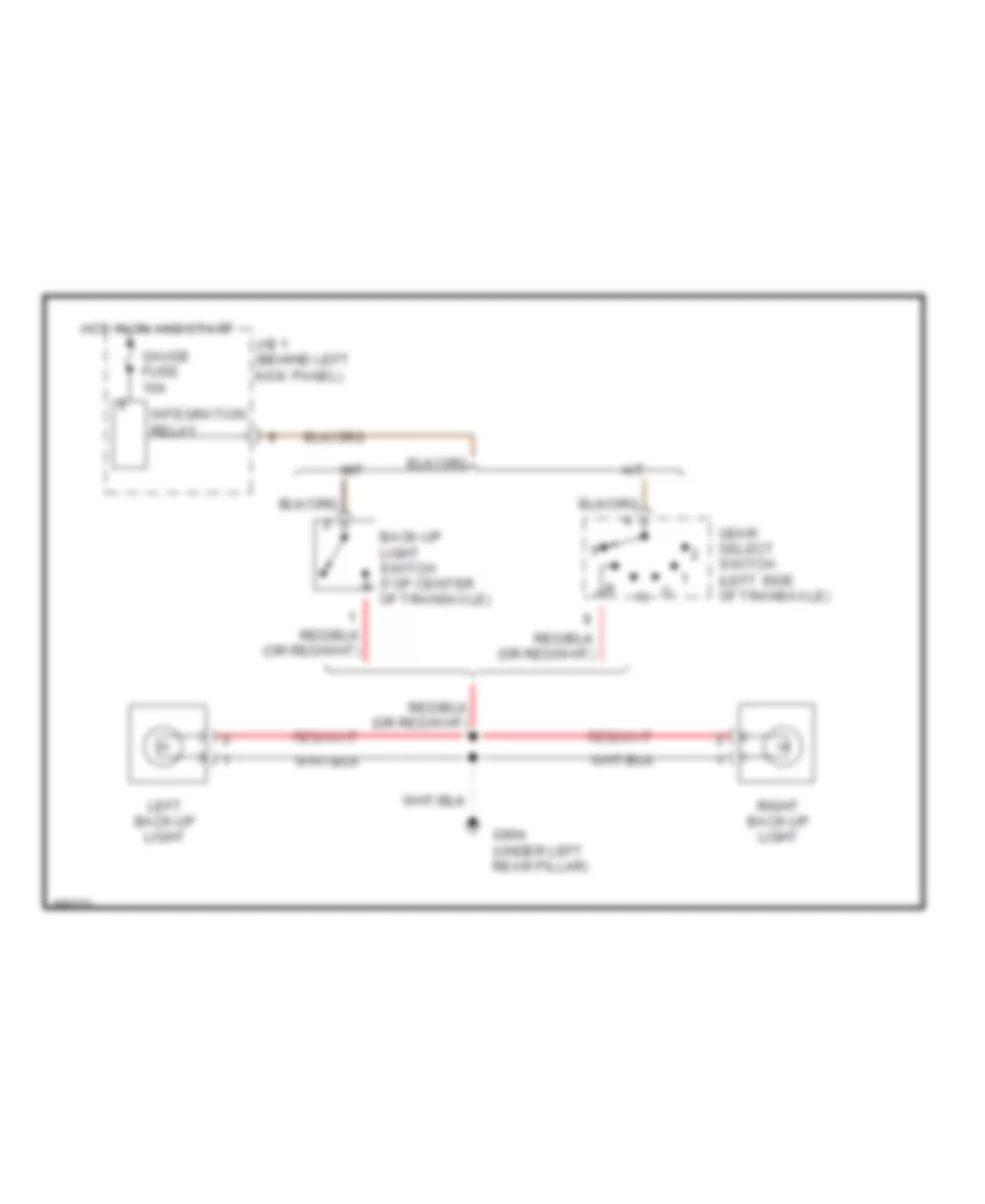
Back-up Lamps Wiring Diagram for Toyota 4Runner SR5 1994
List of elements for Back-up Lamps Wiring Diagram for Toyota 4Runner SR5 1994:
- A/t
- Back-up light switch (top center of transaxle)
- G904 (under left rear pillar)
- Gauge fuse 10a
- Gear select switch (left side of transaxle)
- Hot in on and start
- Integration relay
- J/b 1 (behind left kick panel)
- Left back-up light
- M/t
- Right back-up light
Exterior Light Wiring Diagram for Toyota 4Runner SR5 1994
List of elements for Exterior Light Wiring Diagram for Toyota 4Runner SR5 1994:
- Alt fusible link 100a
- C10
- C11
- C12
- Combination meter
- Combination switch
- G100 (left front fender)
- G101 (right front fender)
- G200 (left kick panel)
- G904 (under left rear pillar)
- G905 (under right rear pillar)
- Haz-horn fuse 15a
- Hazard switch
- Head
- Headlight auto cut out ecu (behind glove box)
- High mount stop light
- Hot at all times
- Hot in on or start
- Integration relay
- J/b 1 (behind left kick panel)
- Left front clearance light
- Left front turn signal light
- Left rear combination light
- Left turn
- License plate lights
- Light switch
- Off
- Park
- R/b 2 (right side of engine compartment)
- Right front clearance light
- Right front turn signal light
- Right rear combination light
- Right turn
- Stop
- Stop fuse 15a
- Stop light switch (on bracket above brake pedal)
- Tail
- Tail fuse 15a
- Taillight relay
- Turn
- Turn fuse 10a
- Turn signal flasher (behind left side of dash)
- Turn signal switch
GROUND DISTRIBUTION
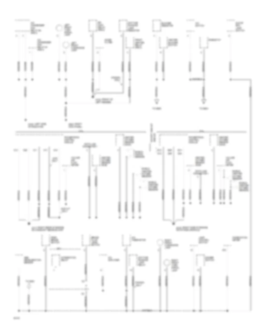
Ground Distribution Wiring Diagram (1 of 3) for Toyota 4Runner SR5 1994
List of elements for Ground Distribution Wiring Diagram (1 of 3) for Toyota 4Runner SR5 1994:
- (front of g100
- (left side g108
- (right g203
- (right rear of engine, g117
- (right side of engine, g120
- 2.4l
- 2wd a/t only
- 3.0l
- 4wd a/t
- 4wd only
- A/c amplifier
- A/c condenser fan relay #1 (r/b 4)
- A/c condenser fan relay #2 (r/b 4)
- A/c switch
- A/c thermistor
- A17
- A18
- Abs deceleration sensor
- Blower resistor
- Brake fluid level switch
- C11
- C13
- C26
- Canada only
- Combination meter
- D10
- D13
- D24
- D26
- Data link connector 1
- Daytime running lamp relay
- Daytime running lamp resistor
- Dimmer switch
- E13
- E14
- E26
- Efi main relay (r/b 2)
- Except 4wd a/t
- Front heater relay (r/b 3)
- Glove box lamp switch
- Heated oxygen sensor (main)
- Heated oxygen sensor (sub)
- Heater blower switch
- Integration relay
- J/b 1
- Kick panel)
- Lamp control switch
- Left fender)
- Left front clearance lamp
- Left front turn signal lamp
- Noise filter
- Of radiator)
- On camshaft bearing cap)
- On intake manifold)
- Park brake switch
- Powertrain control module
- Rheostat
- Right front clearance lamp
- Right front turn signal lamp
- Shield (heated oxygen sensor)
- Shield (knock sensor)
- To g200
- To g904
- To g905
- Volume air flow meter
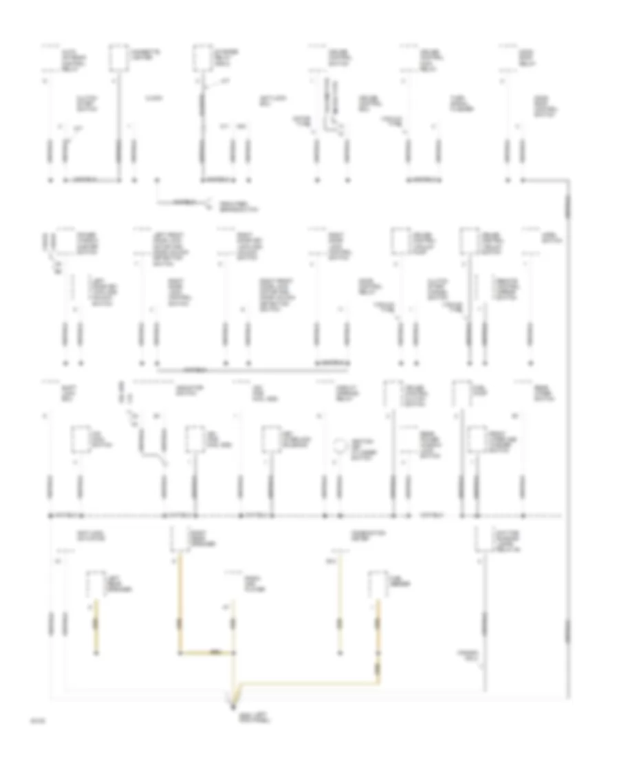
Ground Distribution Wiring Diagram (2 of 3) for Toyota 4Runner SR5 1994
List of elements for Ground Distribution Wiring Diagram (2 of 3) for Toyota 4Runner SR5 1994:
- (left g200
- 2 door
- 2.4l
- 3.0l 4wd
- 4 door
- A/t
- A11
- A24
- Anti-lock actuator
- Anti-lock ecu
- Auto antenna control relay
- B12
- Canada only
- Cigarette lighter
- Circuit opening relay
- Clock
- Clutch start cancel switch
- Clutch start switch
- Combination meter
- Cruise control clutch switch
- Cruise control ecu
- Cruise control main relay
- Cruise control switch
- Cruise control vacuum pump
- Cruise control vacuum switch
- Daytime running lamps relay #4
- Door control relay
- From park brake switch
- Front wiper and washer switch
- Fuel pump
- Fuel sender
- Horn switch
- Ignition key cylinder switch
- Indicator switch
- Key interlock solenoid
- Kick panel)
- Left door key lock and unlock switch
- Left front door lock motor and door unlock detection switch
- Left rear speaker
- M/t
- Moon roof control switch
- Moon roof relay
- Motor type
- O/d main switch
- Power window master switch
- Radio and player
- Rear power window lock switch
- Rear wiper switch
- Remote control mirror switch
- Right door lock control switch
- Right door key lock and unlock switch
- Right front door lock motor and door unlock detection switch
- Right rear speaker
- Shift lock ecu
- Starter relay (r/b 2)
- Turn signal flasher
- Vacuum type
- Vsv (for 2wd, add)
- Vsv (for 4wd, add)
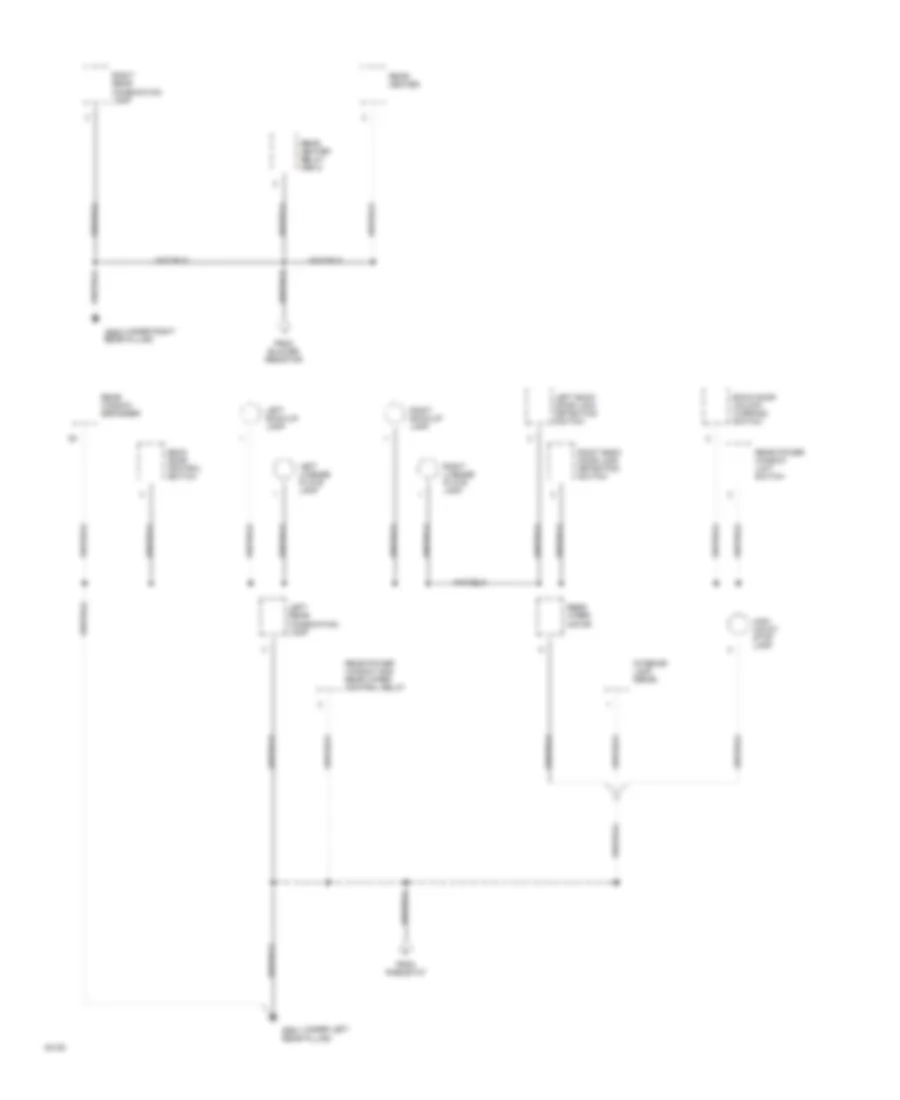
Ground Distribution Wiring Diagram (3 of 3) for Toyota 4Runner SR5 1994
List of elements for Ground Distribution Wiring Diagram (3 of 3) for Toyota 4Runner SR5 1994:
- (under left g904
- (under right g905
- Back door control switch
- Back door unlock warning switch
- From blower resistor
- From rheostat
- High mount stop lamp
- Interior lamp (rear)
- Left back door lock detection switch
- Left back-up lamp
- Left license plate lamp
- Left rear combination lamp
- Rear heater
- Rear heater relay (r/b 3)
- Rear pillar)
- Rear power window and rear wiper control relay
- Rear power window limit switch
- Rear window defogger
- Rear wiper motor
- Right back door lock detection switch
- Right back-up lamp
- Right license plate lamp
- Right rear combination lamp
HEADLIGHTS
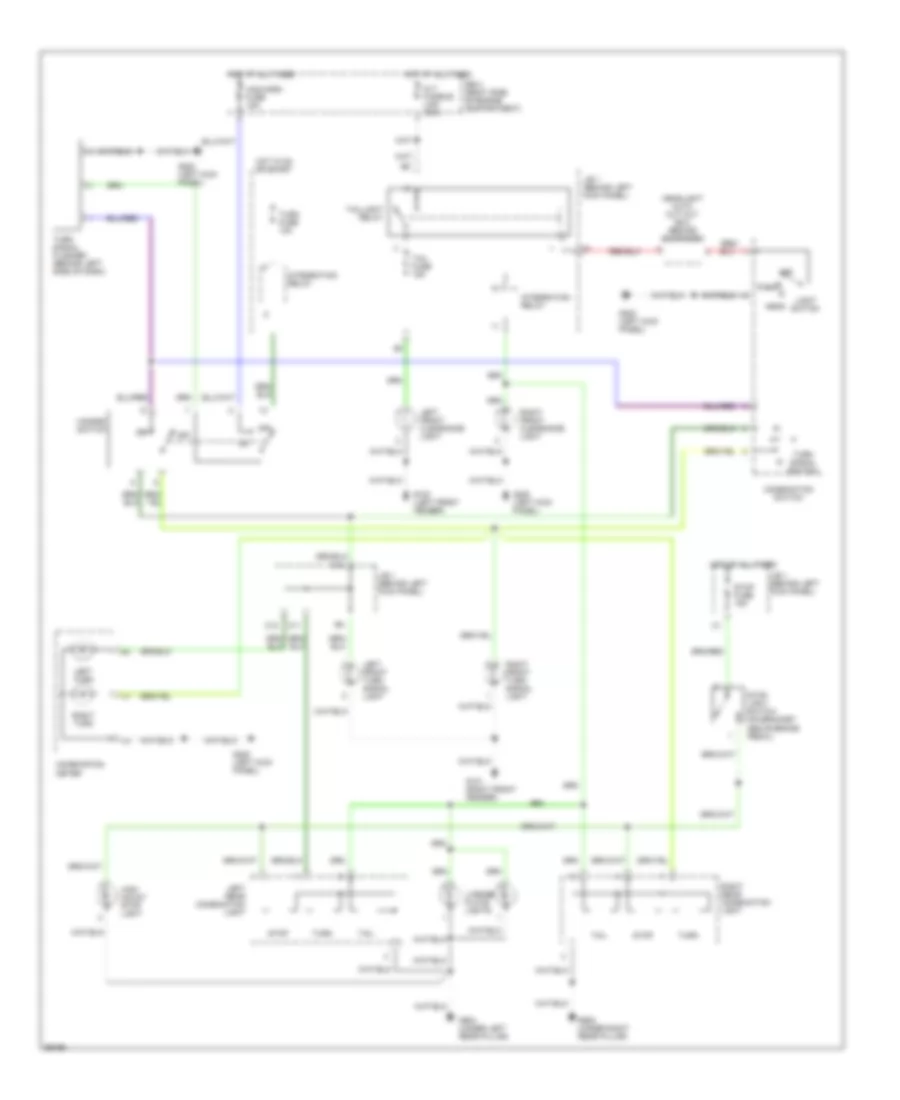
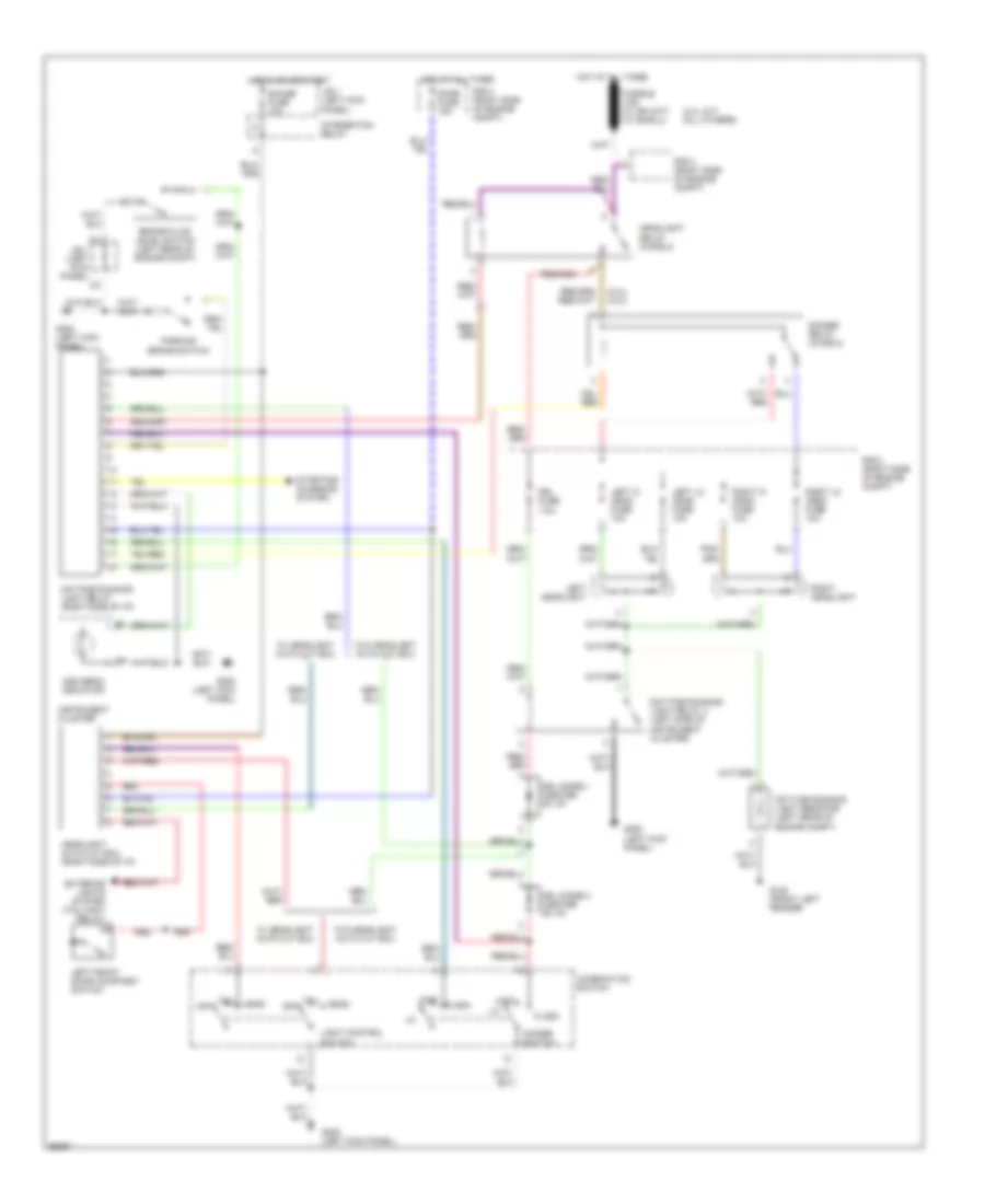
Headlight Wiring Diagram, with DRL for Toyota 4Runner SR5 1994
List of elements for Headlight Wiring Diagram, with DRL for Toyota 4Runner SR5 1994:
- (2.4l a/t) (all others)
- (2.4l) (3.0l)
- Brake fluid level switch (left rear of engine compt)
- Combination switch
- Daytime running light relay (right side of i/p)
- Daytime running light relay 4 (left side of instrument cluster)
- Daytime running light resistor (left rear of engine compt)
- Dimmer relay (in r/b 2)
- Dimmer switch
- Dome fuse 15a
- Drl diode 1 (center of i/p)
- Drl diode 2 (center of i/p)
- Drl fuse 7.5a
- Exterior lights system (taillight relay)
- Flash
- G100 (front left fender)
- G200 (left kick panel)
- Gauge fuse 10a
- Head
- Headlight auto cut ecu (right side of i/p)
- Headlight relay (in r/b 2)
- High
- High beam indicator
- Hot at all times
- Hot in on or start
- Instrument cluster
- Integration relay
- J/b 1 (left kick panel)
- Left front door courtesy switch
- Left headlight
- Left hi head fuse 10a
- Left lo head fuse 10a
- Light control switch
- Off
- Parking brake switch
- R/b 2 (right side of engine compt)
- Red
- Right headlight
- Right hi head fuse 10a
- Right lo head fuse 10a
- Starting/ charging system
- Tail
- W/ headlight auto cut ecu
- W/o headlight auto cut ecu
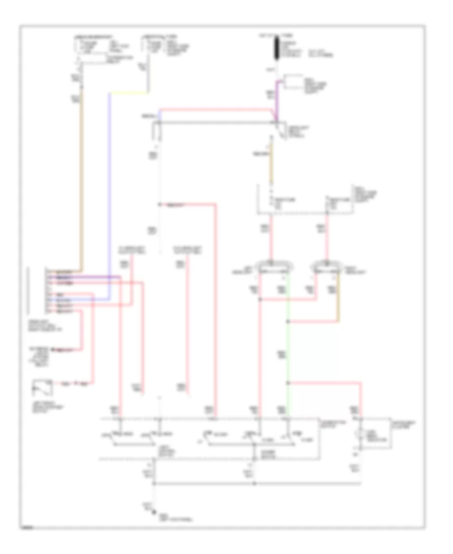
Headlight Wiring Diagram, without DRL for Toyota 4Runner SR5 1994
List of elements for Headlight Wiring Diagram, without DRL for Toyota 4Runner SR5 1994:
- (2.4l a/t) (all others)
- Combination switch
- Dimmer switch
- Dome fuse 15a
- Exterior lights system (taillight relay)
- Flash
- G200 (left kick panel)
- Gauge fuse 10a
- Head
- Head fuse (lh) 10a
- Head fuse (rh) 10a
- Headlight auto cut ecu (right side of i/p)
- Headlight relay (in r/b 2)
- High
- High beam indicator
- Hot at all times
- Hot in on or start
- Instrument cluster
- Integration relay
- J/b 1 (left kick panel)
- Left front door courtesy switch
- Left headlight
- Light control switch
- Off
- R/b 2 (right side of engine compt)
- Red
- Right headlight
- Tail
- W/ headlight auto cut ecu
- W/o headlight auto cut ecu
HORN
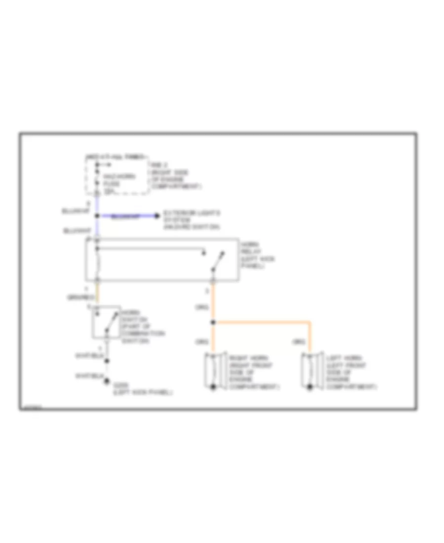
Horn Wiring Diagram for Toyota 4Runner SR5 1994
List of elements for Horn Wiring Diagram for Toyota 4Runner SR5 1994:
- Exterior lights system (hazard switch)
- G200 (left kick panel)
- Haz-horn fuse 15a
- Horn relay (left kick panel)
- Horn switch (part of combination switch)
- Hot at all times
- Left horn (left front side of engine compartment)
- R/b 2 (right side of engine compartment)
- Right horn (right front side of engine compartment)
INSTRUMENT CLUSTER
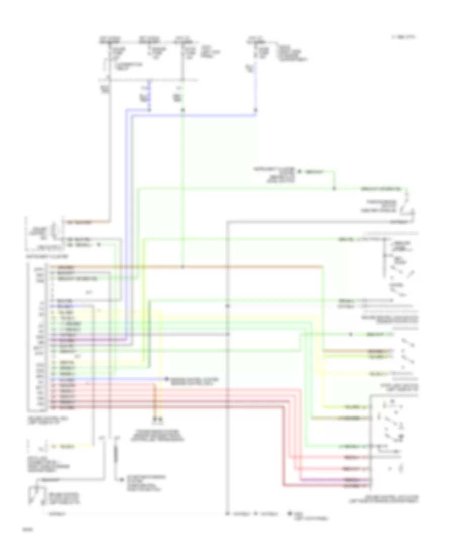
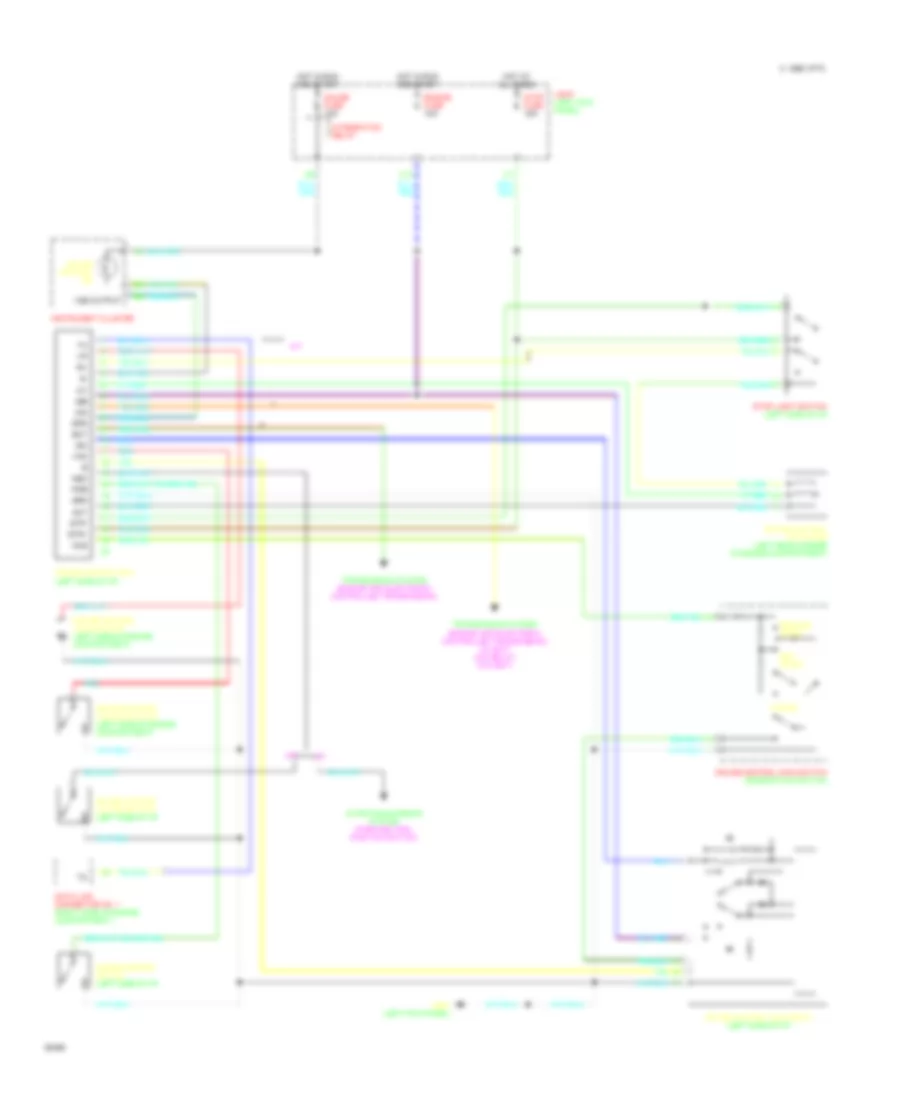
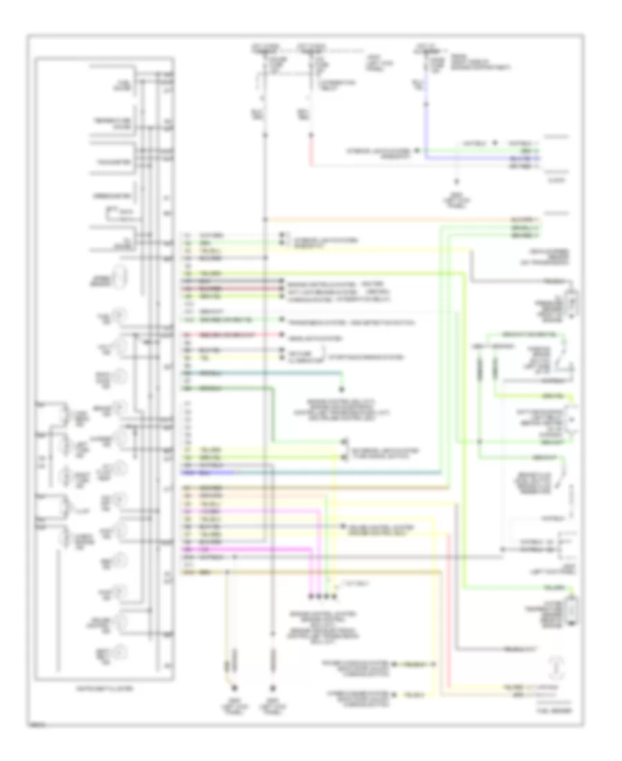
Instrument Cluster Wiring Diagram for Toyota 4Runner SR5 1994
List of elements for Instrument Cluster Wiring Diagram for Toyota 4Runner SR5 1994:
- (abs ecu)
- (add detection switch)
- (igniter)
- (integration relay)
- 4wd ind
- A/t fluid temp
- A/t only
- A10
- A11
- A12
- Abs ind
- Alternator
- Anti-lock brakes system
- Back door ind
- Brake fluid level switch (brake fluid reservoir)
- Brake ind
- C10
- Canada
- Charge ind
- Check engine ind
- Cig fuse 15a
- Clock
- Cruise control ind
- Cruise control system (cruise control ecu)
- D10
- D11
- D12
- Daytime running light relay (behind center of i/p) (canada)
- Dome fuse 15a
- Engine control ecu (m/t), engine and electronic controlled transmission ecu (a/t) and cruise control ecu
- Engine control system (engine control ecu) (m/t) (engine and electronic controlled transmission ecu) (a/t)
- Engine controls system
- Exterior lights system (turn signal switch)
- Fuel gauge
- Fuel ind
- Fuel sender
- G200 (left kick panel)
- Gauge fuse 10a
- Headlights system
- High beam ind
- Hot at all times
- Hot in run and acc
- Ign fuse
- Illum
- Instrument cluster
- Integration relay
- Interior lights system (rheostat)
- J/b #1 (left kick panel)
- Left turn ind
- O/d off ind
- Oil gauge
- Oil pressure sender (front of engine)
- Parking brake switch (left side of i/p)
- Power windows system (back door unlock warning switch)
- Pwr ind
- R/b #2 (right side of engine compartment)
- Right turn ind
- Seat belt ind
- Speed sensor
- Speedometer
- Starting/charging system
- Tachometer
- Temperature gauge
- Transmission system
- Usa
- Vehicle speed sensor (on transmission)
- Volt ind
- Warning system
- Water temperature sender (rear of engine)
- Wiper/washer system (back door unlock warning switch)
INTERIOR LIGHTS
Courtesy Lamps Wiring Diagram for Toyota 4Runner SR5 1994
List of elements for Courtesy Lamps Wiring Diagram for Toyota 4Runner SR5 1994:
- Diode (center of i/p)
- Diode (left rear corner of vehicle)
- Dome fuse 15a
- Door
- Front interior light
- G200 (left kick panel)
- G999 (under left rear pillar)
- Gauge fuse 10a
- Hot at all times
- Hot in start or run
- Integration relay
- J/b #1 (left kick panel)
- Left door courtesy light
- Left front door courtesy switch
- Left rear door courtesy switch
- Left rear door lock detection switch
- Off
- Personal light
- R/b #2 (right side of engine compartment)
- Rear interior light
- Red
- Right door courtesy light
- Right front door courtesy switch
- Right rear door courtesy switch
- Right rear door lock detection switch
- W/ power windows
- W/o power windows
Instrument Illumination Wiring Diagram for Toyota 4Runner SR5 1994
List of elements for Instrument Illumination Wiring Diagram for Toyota 4Runner SR5 1994:
- A/c switch
- C14
- Cigarette lighter illumination
- Clock
- Defogger switch
- Ect pattern select switch
- G200 (left kick panel)
- Glove box light
- Glove box light switch
- Hazard switch
- Head
- Headlight auto cut ecu (right side of i/p)
- Heater blower switch
- Hot at all times
- Instrument cluster
- J/b #1 (left kick panel)
- Light control switch (comb switch)
- O/d main switch
- Off
- Radio and player
- Rear power window lock switch
- Rear power window switch
- Rheostat
- Tail
- Tail fuse 15a
- Taillight relay
- W/o headlight auto cut ecu
POWER ANTENNA
Power Antenna Wiring Diagram for Toyota 4Runner SR5 1994
List of elements for Power Antenna Wiring Diagram for Toyota 4Runner SR5 1994:
- Auto antenna control relay (behind left side of i/p)
- Auto antenna motor (right side of engine compartment)
- C 1995 vftc
- Dome fuse 15a
- G200 (left kick panel)
- Gauge fuse 10a
- Hot at all times
- Hot in acc or on
- Hot in on or start
- Integration relay
- J/b 1 (left kick panel)
- Off
- On player switch
- R/b 2 (right side of engine compartment)
- Radio & player
- Radio fuse 7.5a
- Radio sw
- Solid state
POWER DISTRIBUTION
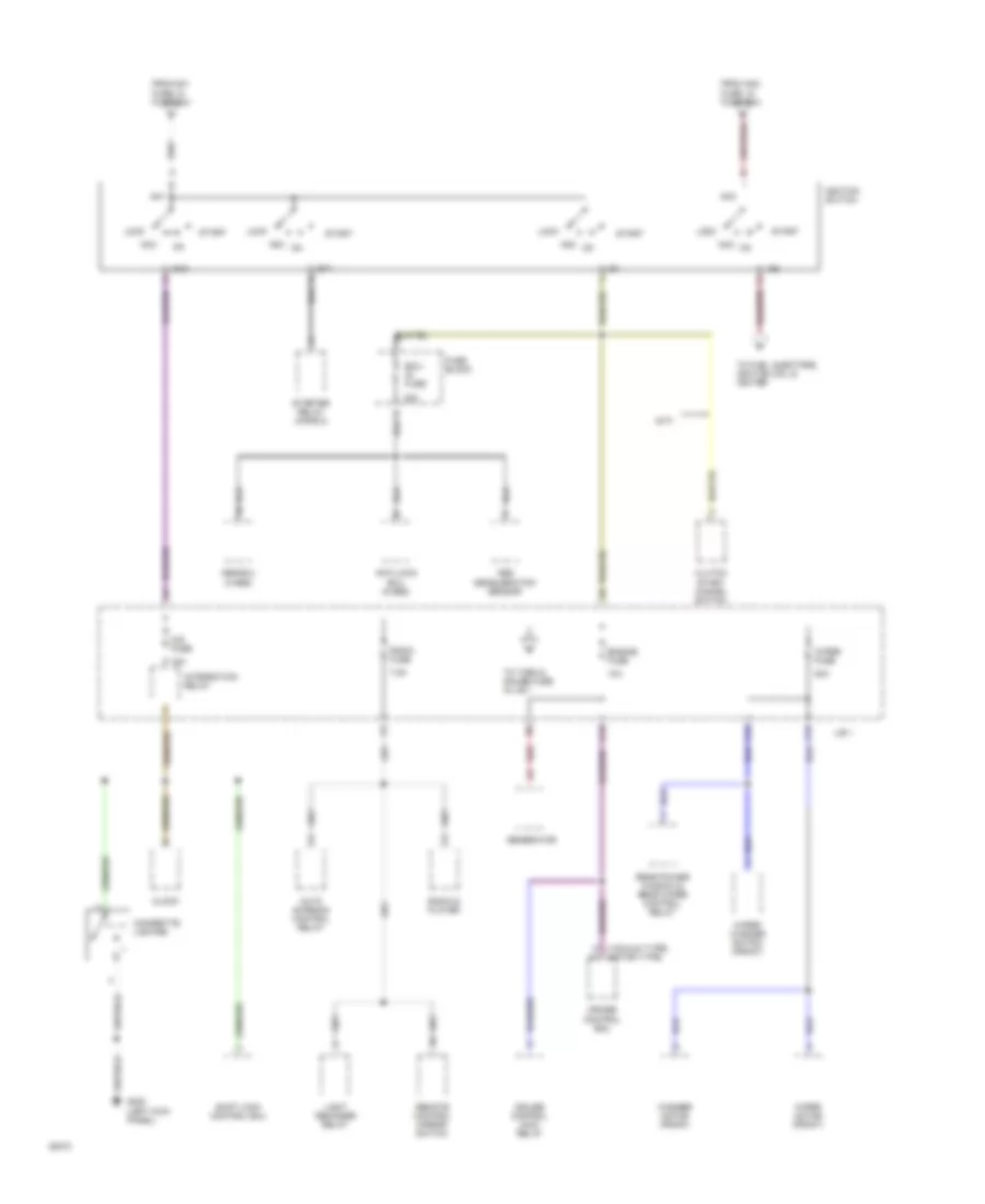
Power Distribution Wiring Diagram (1 of 5) for Toyota 4Runner SR5 1994
List of elements for Power Distribution Wiring Diagram (1 of 5) for Toyota 4Runner SR5 1994:
- (2.4l w/ a/t)
- (4wd a/t, 2.4l) (ex. 4wd m/t, 2.4l) (3.0l)
- (all others)
- 100a
- 15a
- 20a
- 30a
- 40a
- 60a
- 80a
- A1 b2 a1
- A22
- Abs ecu
- Abs fuse (4-abs)
- Abs relay
- Alt fuse
- Am1 fuse
- Am2 fuse
- Anti- lock ecu
- Anti- lock relay
- Anti-lock fuse (2-abs)
- Auto antenna control relay
- Battery
- Clock
- Cruise control ecu
- Defog fuse
- Defogger relay
- Dome fuse
- Door control relay
- Efi fuse
- Efi main relay (engine control system)
- Engine control module
- Front interior light
- Fuse block (left side of i/p)
- Fuse box (r/b 2)
- Haz-horn fuse
- Hazard switch
- Headlight auto cut ecu
- Horn relay
- Integration relay
- J/b 1
- Left door courtesy light
- Left rear speaker
- Main fusible link
- Map light
- Moon roof relay
- Power fuse (left side of i/p)
- R/b 2
- Radio & player
- Rear interior light
- Rear power window & rear wiper control relay
- Rear window defogger
- Right door courtesy light
- Right rear speaker
- To headlight relay, in r/b 2
- To heater fuses, in r/b 3
- To ignition switch, pin 3
- To ignition switch, pin 8
- To taillight relay, in j/b 1
- Unlock warning switch (ignition switch)
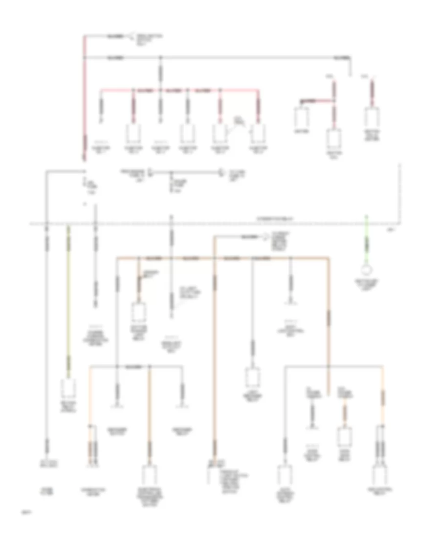
Power Distribution Wiring Diagram (2 of 5) for Toyota 4Runner SR5 1994
List of elements for Power Distribution Wiring Diagram (2 of 5) for Toyota 4Runner SR5 1994:
- (m/t)
- (vacuum type) (motor type)
- 10a
- 15a
- 20a
- 7.5a
- Abs deceleration sensor
- Abs ecu (4-abs)
- Acc
- Am1
- Am2
- Anti-lock ecu (2-abs)
- Auto antenna control relay
- C13
- C15
- C16
- Cig fuse
- Cigarette lighter
- Clock
- Clutch start cancel switch
- Cruise control ecu
- Cruise control main relay
- Ecu- ig fuse
- Engine fuse
- From am1 fuse, in fuse box
- From am2 fuse, in fuse box
- Fuse block
- G200 (left kick panel)
- Generator
- Ig1
- Ig2
- Ignition switch
- Integration relay
- J/b 1
- Light reminder relay
- Lock
- Radio & player
- Radio fuse
- Rear power window & rear wiper control relay
- Red
- Remote control mirror switch
- Shift lock control ecu
- St1
- Start
- Starter relay (in r/b 2)
- To fuel injectors, ignition coil & igniter
- To turn & gauge fuse in j/b 1
- Washer motor (front)
- Wiper fuse
- Wiper motor (front)
- Wiper/ washer switch (front)
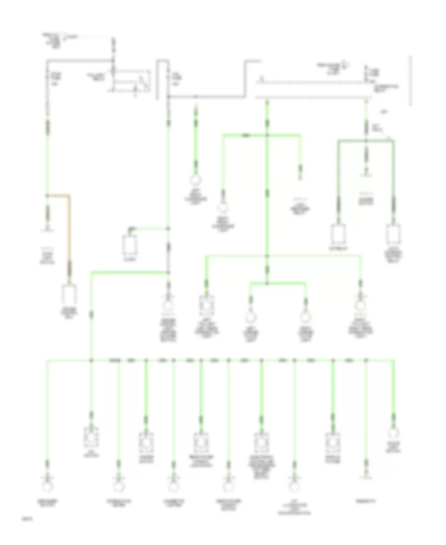
Power Distribution Wiring Diagram (3 of 5) for Toyota 4Runner SR5 1994
List of elements for Power Distribution Wiring Diagram (3 of 5) for Toyota 4Runner SR5 1994:
- (2.4l) (3.0l)
- (3.0l only)
- (a/t) (m/t)
- (canada only)
- (w/ light auto turn off only)
- 10a
- 2.4l
- 3.0l
- 7.5a
- A1 b1
- A4 b2
- Add control relay
- Auto antenna control relay
- Back-up light switch or park/ neutral position switch
- C17
- Charge warning (combination meter)
- Combination meter
- Daytime running light relay
- Defogger relay
- Defogger switch
- Door control relay
- Efi main relay (in r/b 2)
- Electronic controlled transmission pattern switch
- From engine fuse, in
- From ignition switch, pin 7
- Gauge fuse
- Headlight auto cut ecu
- Ign fuse
- Igniter
- Ignition coil
- Ignition coil & igniter
- Ignition key cylinder light
- Injector no. 1
- Injector no. 2
- Injector no. 3
- Injector no. 4
- Injector no. 5
- Injector no. 6
- Integration relay
- J/b 1
- Light reminder relay
- Moon roof relay
- Noise filter
- Shift lock control ecu
- To front & rear heater relays, in r/b 3
- To turn fuse, in j/b 1
- W/ power window
- W/o power window
Power Distribution Wiring Diagram (4 of 5) for Toyota 4Runner SR5 1994
List of elements for Power Distribution Wiring Diagram (4 of 5) for Toyota 4Runner SR5 1994:
- (a/t only)
- 10a
- 15a
- A/c switch
- A/t illumination light (o/d main switch)
- A10
- Auto antenna control relay
- C14
- Cigarette lighter
- Clock
- Combination meter
- Cruise control ecu
- Defogger switch
- Electronic controlled transmission pattern select switch
- From alt fuse, in fuse box
- From gauge h fuse, in j/b 1
- Glove light switch
- Hazard switch
- Heater control light (heater blower switch)
- Integration relay
- J/b 1
- Left front clearance light
- Left license plate light
- Left taillight (left rear conbination light)
- Light reminder relay
- O/d relay
- Radio & player
- Rear power window lock swich
- Rear power window switch
- Rheostat
- Right front clearance light
- Right license plate light
- Right taillight (right rear conbination light)
- Stop fuse
- Stop light switch
- Tail fuse
- Taillight relay
- Turn fuse
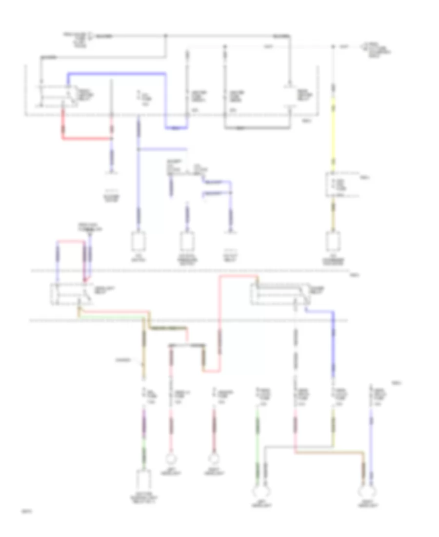
Power Distribution Wiring Diagram (5 of 5) for Toyota 4Runner SR5 1994
List of elements for Power Distribution Wiring Diagram (5 of 5) for Toyota 4Runner SR5 1994:
- 10a
- 20a
- 3.0l w/ 4wd a/t
- 30a
- 40a
- 7.5a
- A/c condenser fan motor
- A/c cut relay
- A/c dual pressure switch
- A/c fuse
- A/c switch
- Blower motor
- Canada
- Cda fan fuse
- Daytime running light relay no. 4
- Dimmer relay
- Drl fuse
- Except 3.0l w/ 4wd a/t
- From alt fuse in fuse box (r/b 2)
- From gauge fuse, in j/b 1 pin d9
- From main fusible link
- Front heater relay
- Head (lh-hi) fuse
- Head (lh-lo) fuse
- Head (rh-hi) fuse
- Head (rh-lo) fuse
- Head lh fuse
- Head rh fuse
- Headlight relay
- Heater fuse (front)
- Heater fuse (rear)
- Left headlight
- R/b 2
- R/b 3
- R/b 4
- Rear heater relay
- Red
- Right headlight
- Usa
POWER DOOR LOCKS
Power Door Lock Wiring Diagram for Toyota 4Runner SR5 1994
List of elements for Power Door Lock Wiring Diagram for Toyota 4Runner SR5 1994:
- 1995 vftc c
- Cassette r/b (left kick panel)
- Dome fuse 15a
- Door lock control relay (left side of i/p)
- G200 (left kick panel)
- Hot at all times
- Left door courtesy switch
- Left door key lock/unlock switch
- Left door lock control switch
- Left door lock motor and unlock detection switch
- Left rear door lock motor
- Lock
- Lock timer
- Power fuse 30a
- R/b #2 (right side of engine compartment)
- Red
- Right door courtesy switch
- Right door key lock/unlock switch
- Right door lock control switch
- Right door lock motor and unlock detection switch
- Right rear door lock motor
- Solid state
- Unlock
- Unlock timer
- Unlock warning switch (ignition switch)
POWER MIRRORS
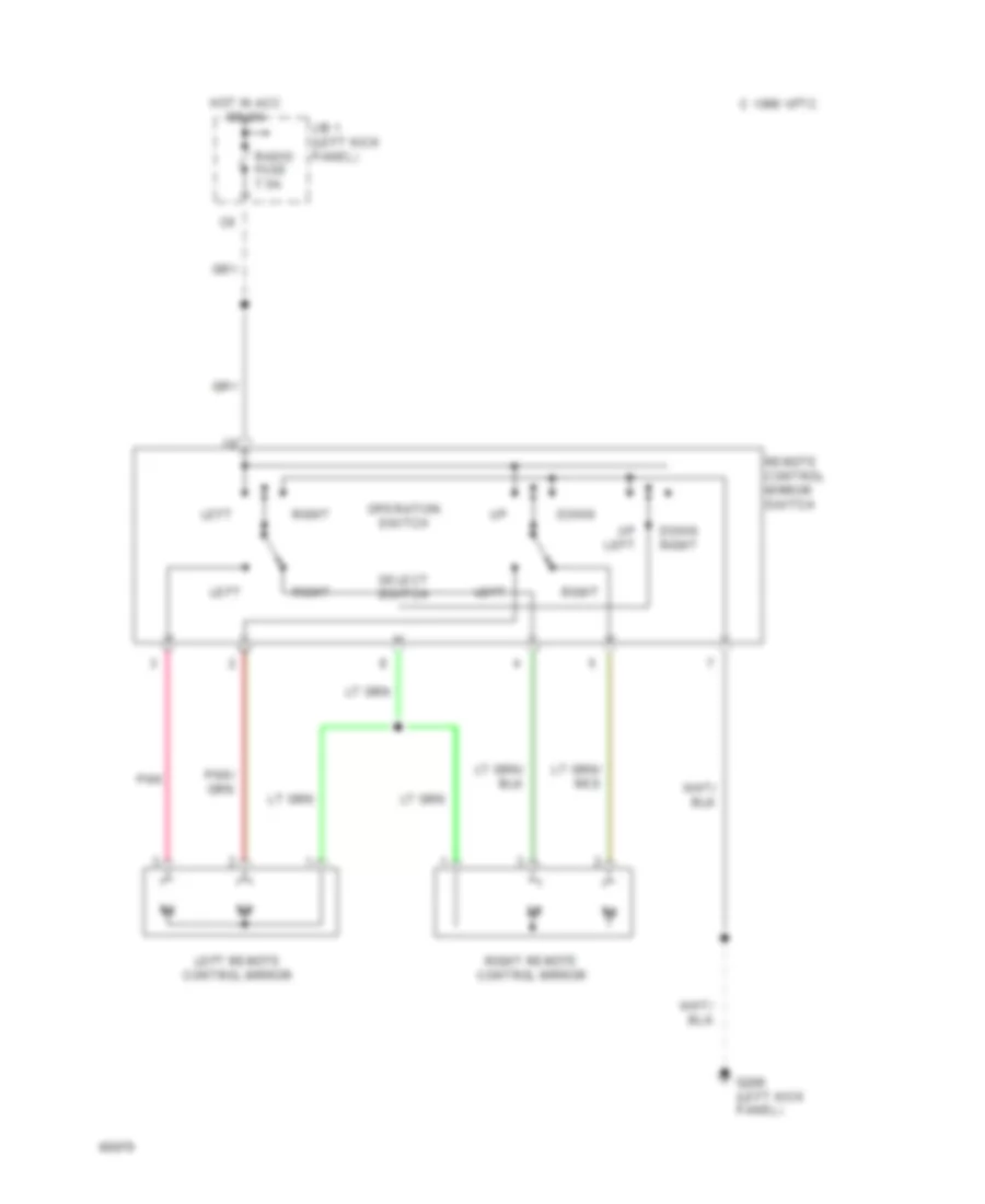
Power Mirror Wiring Diagram for Toyota 4Runner SR5 1994
List of elements for Power Mirror Wiring Diagram for Toyota 4Runner SR5 1994:
- C 1995 vftc
- Down
- Down right
- G200 (left kick panel)
- Hot in acc or on
- J/b 1 (left kick panel)
- Left
- Left remote control mirror
- Operation switch
- Pnk
- Radio fuse 7.5a
- Remote control mirror switch
- Right
- Right remote control mirror
- Select switch
- Up left
POWER TOP/SUNROOF
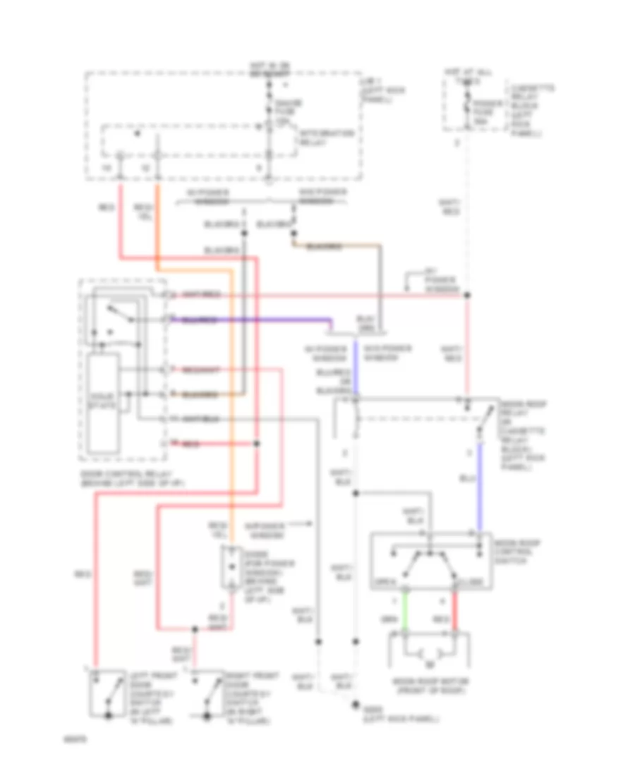
Moonroof Wiring Diagram for Toyota 4Runner SR5 1994
List of elements for Moonroof Wiring Diagram for Toyota 4Runner SR5 1994:
- Cassette relay block (left kick panel)
- Close
- Diode (for power window) (behind left side of i/p)
- Door control relay (behind left side of i/p)
- G200 (left kick panel)
- Gauge fuse 10a
- Hot at all times
- Hot in on or start
- Integration relay
- J/b 1 (left kick panel)
- Left front door courtesy switch (in left "a" pillar)
- Moon roof control switch
- Moon roof motor (front of roof)
- Moon roof relay (in cassette relay block) (left kick panel)
- Open
- Power fuse 30a
- Red
- Right front door courtesy switch (in right "a" pillar)
- Solid state
- W/ power window
- W/o power window
- W/power window
POWER WINDOWS
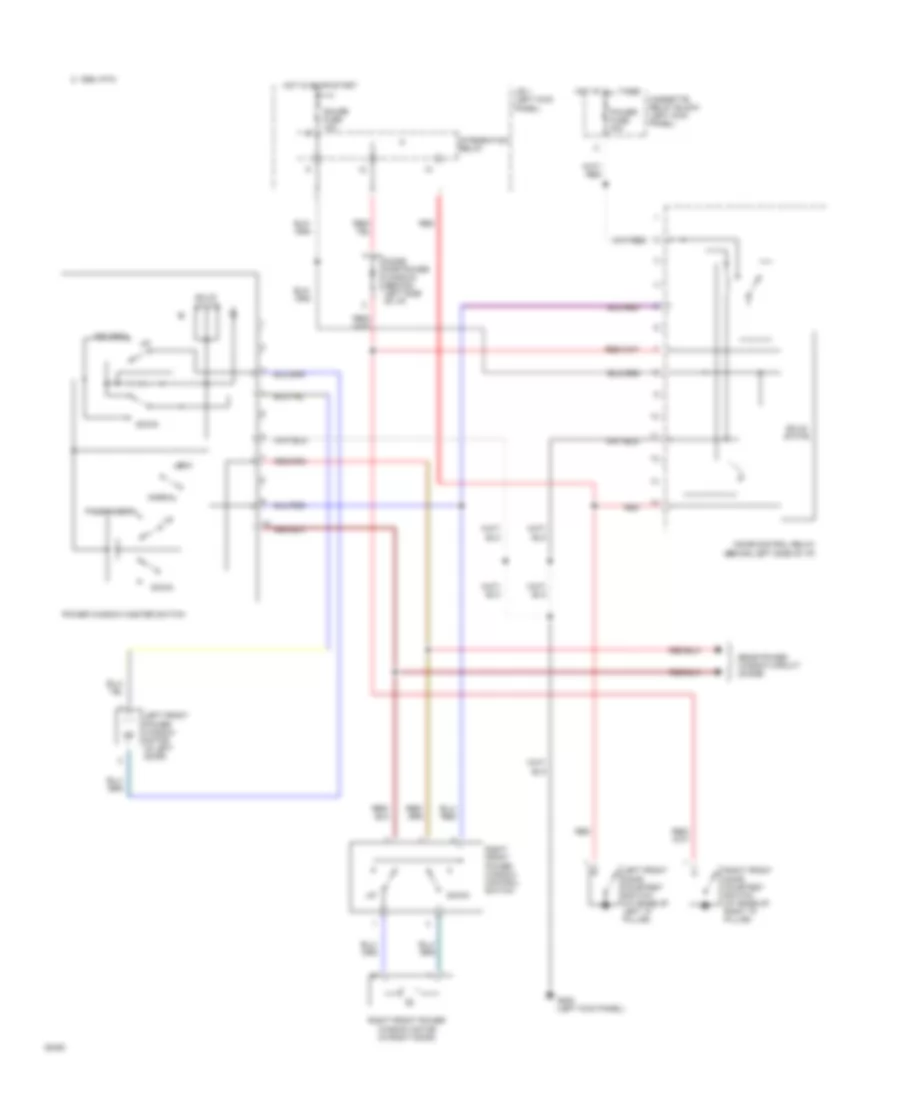
Power Window Wiring Diagram, 2 Door for Toyota 4Runner SR5 1994
List of elements for Power Window Wiring Diagram, 2 Door for Toyota 4Runner SR5 1994:
- C 1995 vftc
- Cassette relay block (left kick panel)
- Diode (for power window) (behind left side of i/p)
- Door control relay (behind left side of i/p)
- Down
- Driver's
- G200 (left kick panel)
- Gauge fuse 10a
- Hot at all times
- Hot in on or start
- Integration relay
- J/b 1 (left kick panel)
- Left front door courtesy switch (at base of left "a" pillar)
- Left front power window motor (in left door)
- Lock
- Normal
- Passenger's
- Power fuse 30a
- Power window master switch
- Rear power window circuit (diode)
- Red
- Right front door courtesy switch (at base of right "a" pillar)
- Right front power window control switch
- Right front power window motor (in right door)
- Solid state
Power Window Wiring Diagram, 4 Door for Toyota 4Runner SR5 1994
List of elements for Power Window Wiring Diagram, 4 Door for Toyota 4Runner SR5 1994:
- C 1995 vftc
- Cassette relay block (left kick panel)
- Diode (for power window) (behind left side of i/p)
- Door control relay (behind left side of i/p)
- Down
- Driver's
- G200 (left kick panel)
- Gauge fuse 10a
- Hot at all times
- Hot in on or start
- Integration relay
- J/b 1 (left kick panel)
- Left front door courtesy switch (at base of left "a" pillar)
- Left front power window motor (in left front door)
- Left rear
- Left rear power window control switch
- Left rear power window motor (in left rear door)
- Lock
- Normal
- Passenger's
- Power fuse 30a
- Power window master switch
- Rear power window circuit (diode)
- Red
- Right front door courtesy switch (at base of right "a" pillar)
- Right front power window control switch
- Right front power window motor (in right front door)
- Right rear
- Right rear power window control switch
- Right rear power window motor (in right rear door)
- Solid state
Power Window Wiring Diagram, Rear for Toyota 4Runner SR5 1994
List of elements for Power Window Wiring Diagram, Rear for Toyota 4Runner SR5 1994:
- Back door
- Back door control switch
- Back door unlock warning switch (center of rear door)
- C 1995 vftc
- C16
- Cassette relay block (left kick panel)
- Combination meter
- Diode
- Down
- Front power windows circuit (power window master switch & right front control switch)
- G200 (left kick panel)
- G904 (under left rear pillar)
- Gauge fuse 10a
- Hot at all times
- Hot in on or start
- Integration relay
- J/b 1 (left kick panel)
- Left back door detection switch (left side of rear door)
- Power fuse 30a
- Rear power limit switch (center of rear door)
- Rear power window & rear wiper control relay (left rear side of cargo area, behind trim panel)
- Rear power window lock switch (in left rear door)
- Rear power window motor (center of rear door above window)
- Rear power window switch
- Red
- Right back door detection switch (right side of rear door)
- Solid state
- W/ front power windows
- W/o front power windows
- Wiper fuse 20a
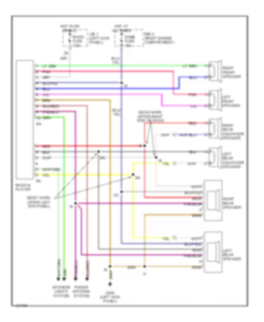
RADIO
Radio Wiring Diagrams for Toyota 4Runner SR5 1994
List of elements for Radio Wiring Diagrams for Toyota 4Runner SR5 1994:
- (body harn, upper left qtr panel)
- (dash harn, upper right side of dash)
- Dome fuse 15a
- G200 (left kick panel)
- Hot at all times
- Hot in on or acc
- I12
- Interior lights system
- J/b 1 (left kick panel)
- Left front speaker
- Left rear speaker
- Left rear squawker speaker
- Pnk
- Power antenna system
- R/b 2 (right engine compartment)
- Radio & player
- Radio fuse 7.5a
- Red
- Red
- Right front speaker
- Right rear speaker
- Right rear squawker speaker
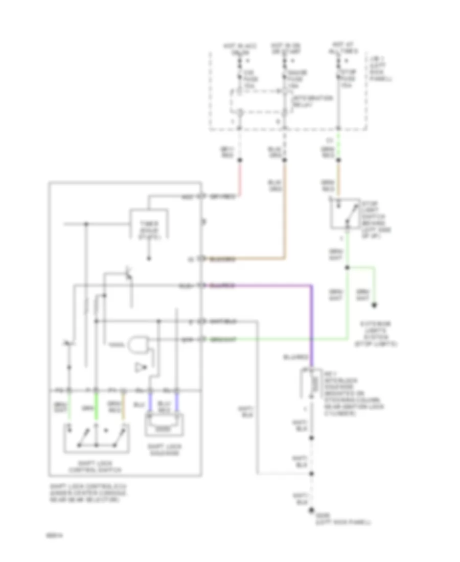
SHIFT INTERLOCKS
Shift Interlock Wiring Diagram for Toyota 4Runner SR5 1994
List of elements for Shift Interlock Wiring Diagram for Toyota 4Runner SR5 1994:
- Acc
- Cig fuse 15a
- Exterior lights system (stop lights)
- G200 (left kick panel)
- Gauge fuse 10a
- Hot at all times
- Hot in acc or on
- Hot in on or start
- Integration relay
- J/b 1 (left kick panel)
- Key interlock solenoid (mounted on steering column, near ignition lock cylinder)
- Kls+
- Shift lock control ecu (under center console, near gear selector)
- Shift lock control switch
- Shift lock solenoid
- Sl+
- Sl-
- Stop fuse 15a
- Stop light switch (behind left side of i/p)
- Stp
- Timer (solid state)
STARTING/CHARGING
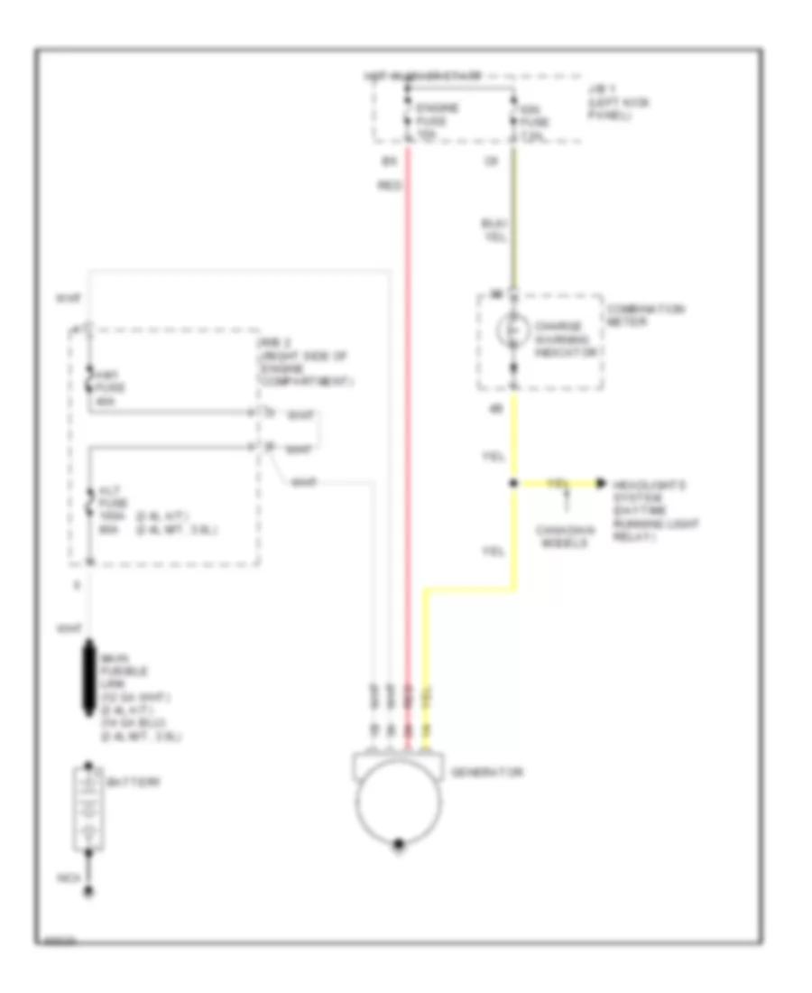
Charging Wiring Diagram for Toyota 4Runner SR5 1994
List of elements for Charging Wiring Diagram for Toyota 4Runner SR5 1994:
- (2.4l a/t) (2.4l m/t, 3.0l)
- Alt fuse 100a 80a
- Am1 fuse 40a
- Battery
- Canadian models
- Charge warning indicator
- Combination meter
- Engine fuse 10a
- Generator
- Headlights system (daytime running light relay)
- Hot in on or start
- Ign fuse 7.5a
- J/b 1 (left kick panel)
- Nca
- R/b 2 (right side of engine compartment)
- Red
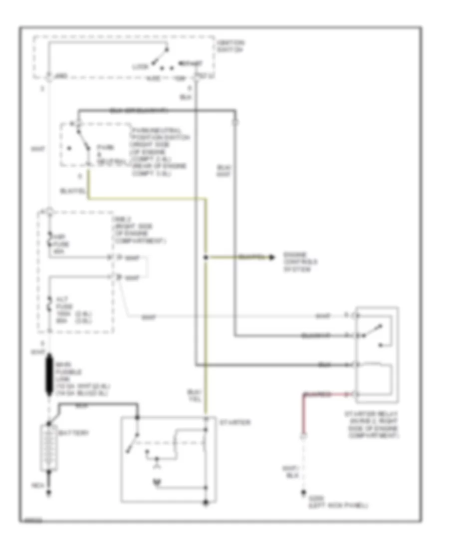
Starting Wiring Diagram, A/T for Toyota 4Runner SR5 1994
List of elements for Starting Wiring Diagram, A/T for Toyota 4Runner SR5 1994:
- (2.4l) (3.0l)
- Acc
- Alt fuse 100a 80a
- Am1
- Am1 fuse 40a
- Battery
- Engine controls system
- G200 (left kick panel)
- Ignition switch
- Lock
- Nca
- Park & neutral
- Park/neutral position switch (right side of engine compt 2.4l) (rear of engine compt 3.0l)
- R/b 2 (right side of engine compartment)
- St1
- Start
- Starter
- Starter relay (in r/b 2, right side of engine compartment)
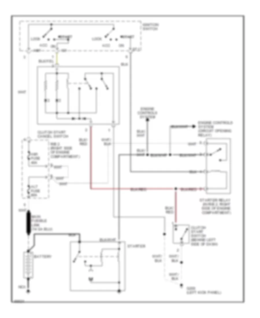
Starting Wiring Diagram, M/T for Toyota 4Runner SR5 1994
List of elements for Starting Wiring Diagram, M/T for Toyota 4Runner SR5 1994:
- Acc
- Alt fuse 80a
- Am1
- Am1 fuse 40a
- Battery
- Clutch start cancel switch
- Clutch start switch (behind left side of dash)
- Engine controls system
- Engine controls system (circuit opening relay)
- G200 (left kick panel)
- Ig1
- Ignition switch
- Lock
- Nca
- R/b 2 (right side of engine compartment)
- St1
- Start
- Starter
- Starter relay (in r/b 2, right side of engine compartment)
TRANSMISSION
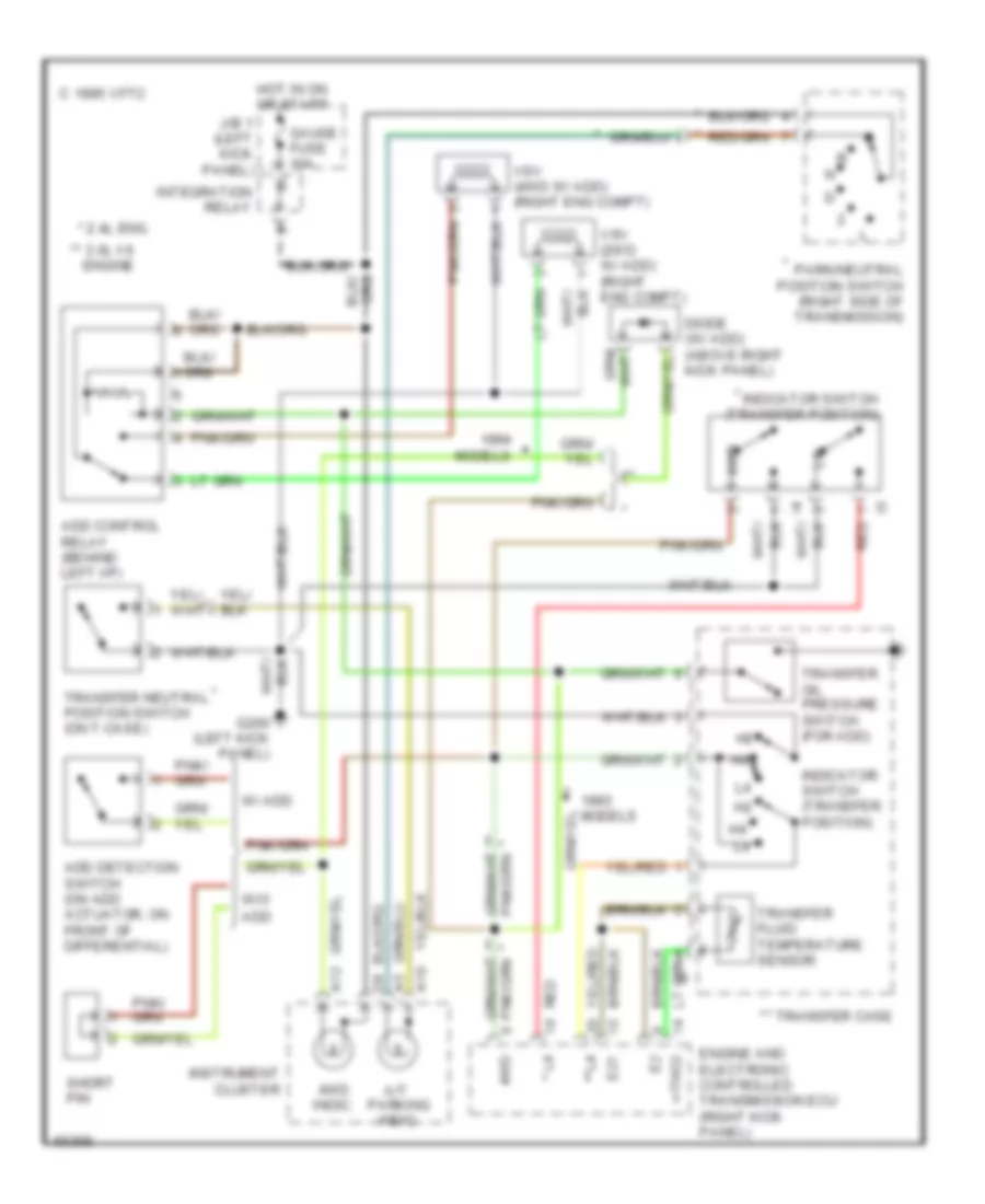
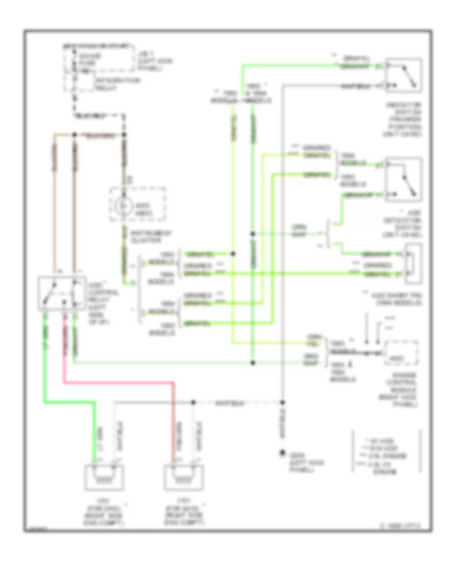
Transfer Case Wiring Diagram, A/T for Toyota 4Runner SR5 1994
List of elements for Transfer Case Wiring Diagram, A/T for Toyota 4Runner SR5 1994:
- * **
- * 2.4l eng.
- ** *
- ** 3.0l v6 engine
- 1995 vftc c
- 4wd
- 4wd indic.
- A/t parking indic.
- A10
- A12
- Add
- Add control relay (behind left i/p)
- Add detection switch (on add actuator, on front of differential)
- Diode (w/ add) (above right kick panel)
- E21
- Engine and electronic controlled transmission ecu (right kick panel)
- G200 (left kick panel)
- Gauge fuse 10a
- Hot in on or start
- Indicator switch (transfer position)
- Instrument cluster
- Integration relay
- J/b 1 (left kick panel)
- Models
- Park/neutral position switch (right side of transmission)
- Red
- Short pin
- Tho2
- Transfer case
- Transfer fluid temperature sensor
- Transfer neutral position switch (on t-case)
- Transfer oil pressure switch (for add)
- Vsv (2wd w/ add) (right eng compt)
- Vsv (4wd w/ add) (right eng compt)
- W/ add
- W/o
Transfer Case Wiring Diagram, M/T for Toyota 4Runner SR5 1994
List of elements for Transfer Case Wiring Diagram, M/T for Toyota 4Runner SR5 1994:
- & 1994 models
- (for 4wd) (right side eng compt)
- (left side of i/p)
- * w/ add
- ** w/o add
- ***
- *** ****
- *** 2.5l engine
- ****
- **** 3.0l v6
- 1993 & models
- 4wd
- 4wd indic.
- A12
- Add control relay
- Add detection switch (on t-case)
- Add short pin (1994 models)
- C 1995 vftc
- Engine
- Engine control module (right kick panel)
- G200 (left kick panel)
- Gauge fuse 10a
- Hot in on or start
- Indicator switch (tranfer position) (on t-case)
- Instrument cluster
- Integration relay
- J/b 1 (left kick panel)
- Models
- Vsv
- Vsv (for 2wd) (right side eng compt)
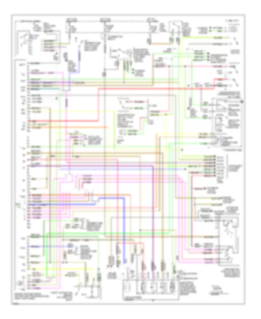
Transmission Wiring Diagram for Toyota 4Runner SR5 1994
List of elements for Transmission Wiring Diagram for Toyota 4Runner SR5 1994:
- (1994) **
- (4wd)
- (starter
- * **
- * w/ 2.4l
- ** *
- ** w/ 3.0l v6 engine
- +b1
- 1995 vftc c
- 2wd
- 4wd
- Add
- Add detection switch (on add actuator, on front of differential)
- Batt
- C17
- Cruise control system
- Data link connector 1 (right side eng compt)
- Dg te2 t e1
- E21
- Efi fuse 15a
- Efi main
- Electronic controlled transmission pattern select switch
- Electronic controlled transmission solenoid and vehicle speed sensor
- Engine
- Engine and electronic controlled transmission ecu (right kick panel)
- Engine controls system
- Engine coolant temperature sensor (on intake manifold)
- Exterior lights system
- G100 (front of left front fender)
- G117 (cam bearing cap)
- G120 (intake manifold)
- Gauge fuse 10a
- Hot at all times
- Hot in on or start
- Idl
- Ign fuse 7.5a
- Indicator switch (transfer position)
- Indicator switch (transfer position) (on t-case)
- Instrument cluster system
- Integration relay
- Interior lights system
- J/b 1 (left kick panel)
- Models
- N **
- No. 1
- No. 2
- No. 3
- No. 4
- Norm
- O/d main switch
- Od1
- Od2
- Oil
- Oil temperature sensor (right front trans pan)
- Oil temperature switch (right side eng compt)
- Park/neutral position switch (right side of transmission)
- Pin a12
- Pin a5
- Pin b6
- Pin c2 (not used)
- Pin c7
- Pin d2
- Pin d4
- Pwr
- R/b 2 (right eng compt)
- Red
- Relay
- Relay)
- Short pin
- Sp1
- Sp2
- Sta
- Starting/ charging system
- Stop fuse 15a
- Stop light switch (above brake pedal)
- Stp
- Te2
- Te2 th02
- Th01
- Throttle position sensor (on throttle body)
- Thw
- Transfer case
- Transfer fluid temperature sensor
- Transfer oil pressure switch (for add)
- Transmissions systems (a/t transfer case circuit)
- Vcc
- Vehicle speed sensor
- Vta
- W/ add
- W/o
WARNING SYSTEMS
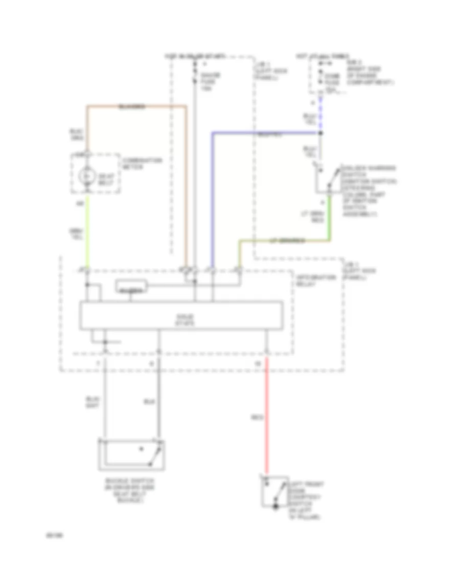
Warning System Wiring Diagrams for Toyota 4Runner SR5 1994
List of elements for Warning System Wiring Diagrams for Toyota 4Runner SR5 1994:
- Buckle switch (in driver's side seat belt buckle)
- Buzzer
- Combination meter
- Dome fuse 15a
- Gauge fuse 10a
- Hot at all times
- Hot in on or start
- Integration relay
- J/b 1 (left kick panel)
- Left front door courtesy switch (in left "a" pillar)
- R/b 2 (right side of engine compartment)
- Red
- Seat belt
- Solid state
- Unlock warning switch (ignition switch) (steering column, part of ignition switch assembly)
WIPER/WASHER
Front Wiper/Washer Wiring Diagram for Toyota 4Runner SR5 1994
List of elements for Front Wiper/Washer Wiring Diagram for Toyota 4Runner SR5 1994:
- C15
- C16
- Combination switch
- G200 (left kick panel)
- High
- Hot in on or start
- Int
- J/b 1 (left kick panel)
- Low/ mist
- Off
- Solid state
- Washer
- Washer motor (in washer fluid reservoir, right front corner of engine compartment)
- Wiper & washer switch
- Wiper fuse 20a
- Wiper motor (right rear corner of engine compartment)
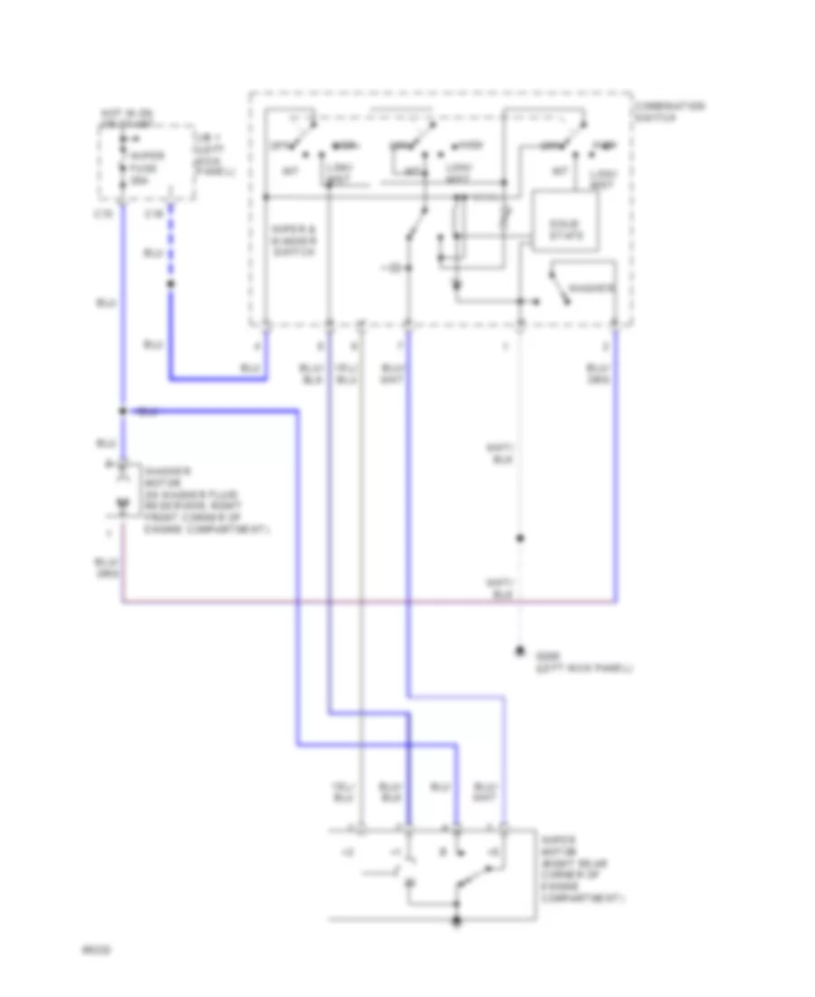
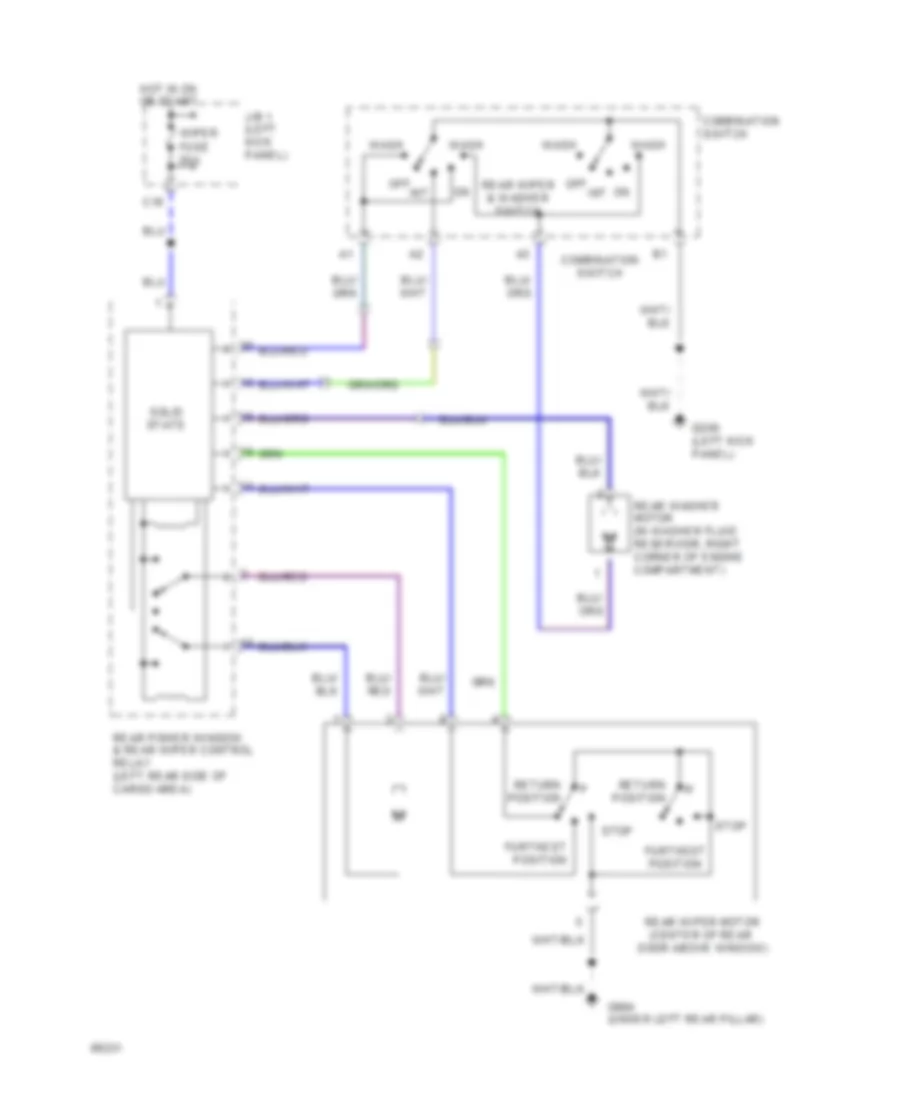
Rear Wiper/Washer Wiring Diagram for Toyota 4Runner SR5 1994
List of elements for Rear Wiper/Washer Wiring Diagram for Toyota 4Runner SR5 1994:
- C16
- Combination switch
- Furthest position
- G200 (left kick panel)
- G904 (under left rear pillar)
- Hot in on or start
- Int
- J/b 1 (left kick panel)
- Off
- On int
- Rear power window & rear wiper control relay (left rear side of cargo area)
- Rear washer motor (in washer fluid reservoir, right corner of engine compartment)
- Rear wiper & washer switch
- Rear wiper motor (center of rear door above window)
- Return position
- Solid state
- Stop
- Wash
- Wiper fuse 20a