AIR CONDITIONING
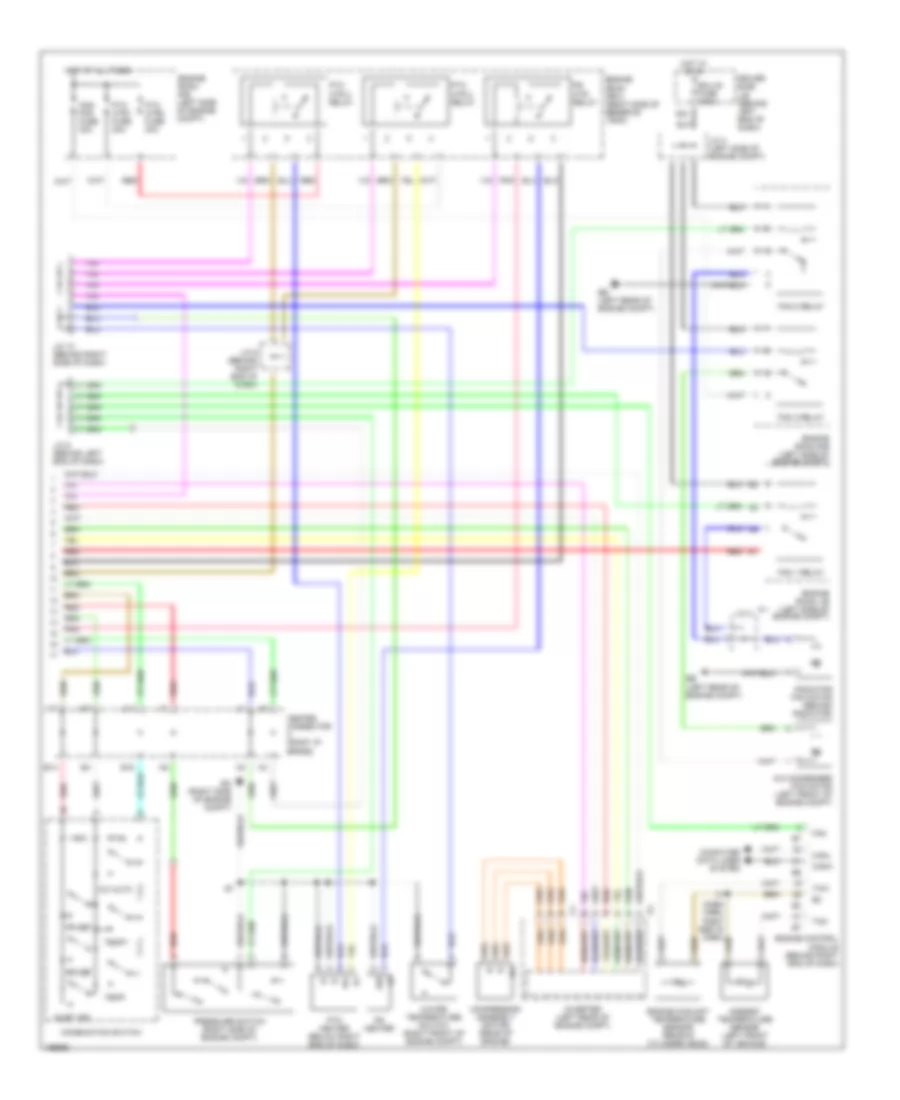
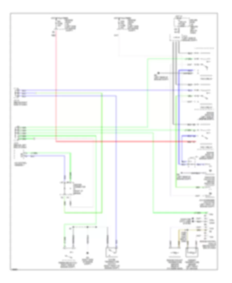
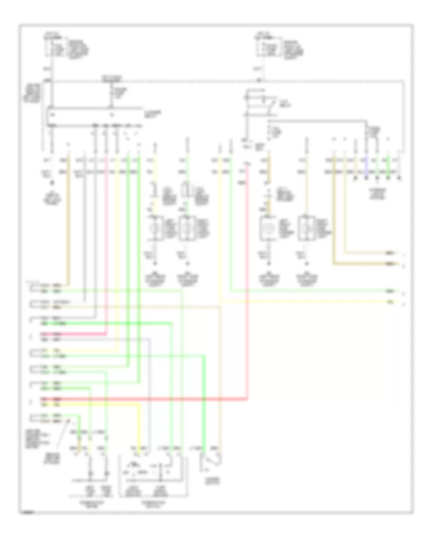
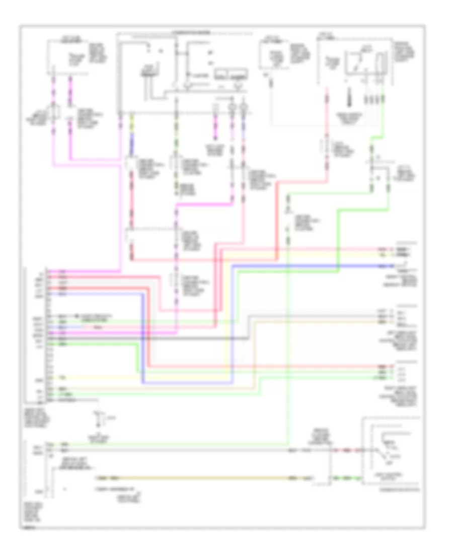
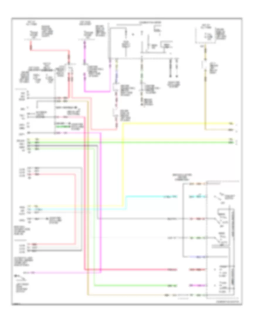
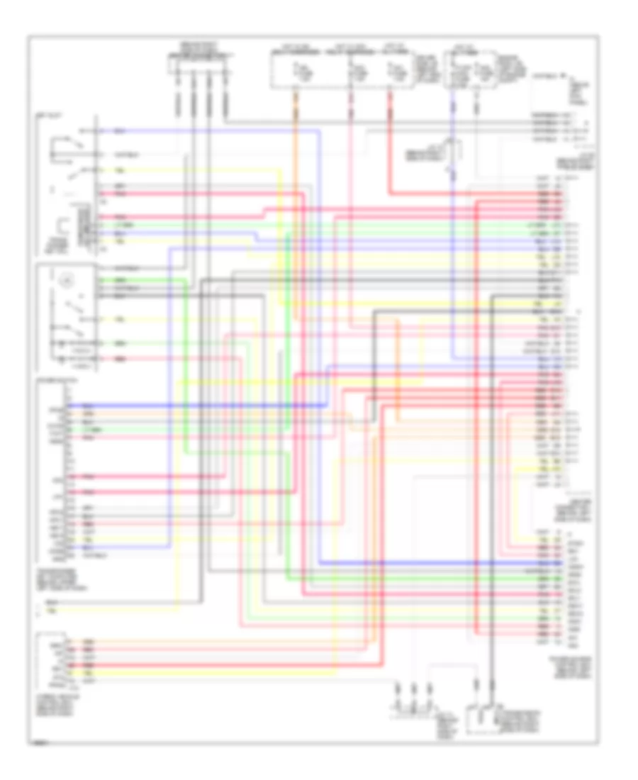
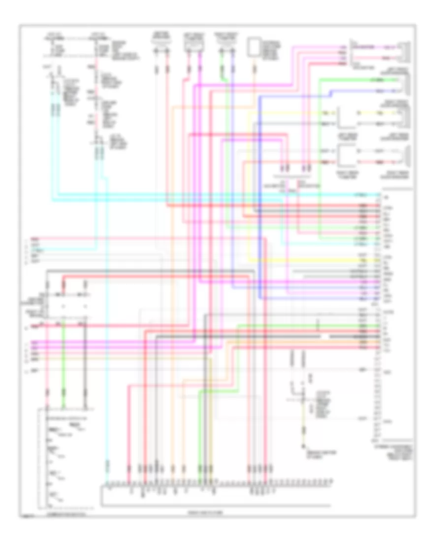
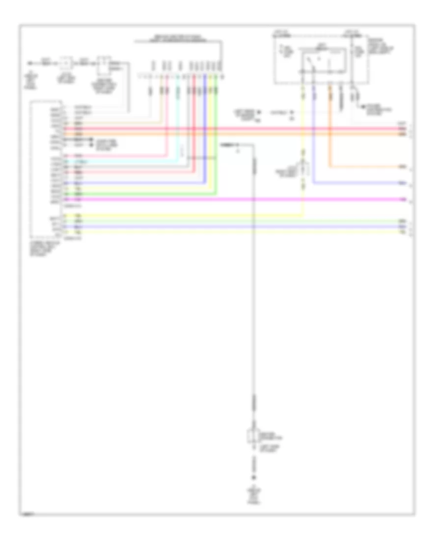
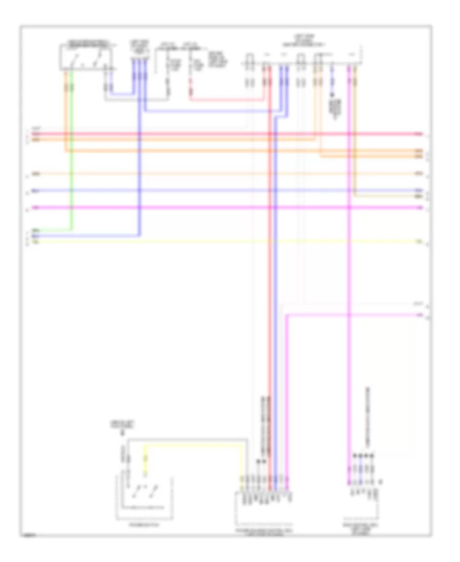
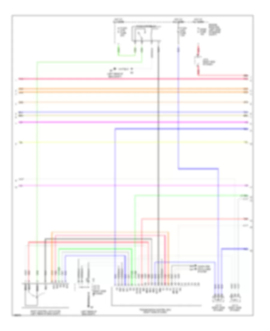
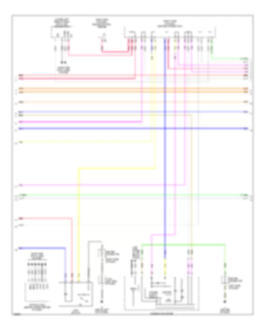
Automatic A/C Wiring Diagram (1 of 2) for Toyota Prius 2004

List of elements for Automatic A/C Wiring Diagram (1 of 2) for Toyota Prius 2004:
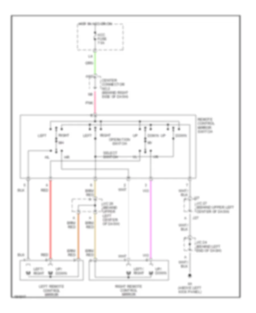
- (behind center of dash)
- A/c (htr) fuse 50a
- A/c control assembly
- A/c room temp sensor (left center of dash)
- A/c solar sensor (top right side of dash)
- A/c thermistor (lower center of dash)
- A/c w/p relay
- A19
- A29
- Aif
- Air
- Air inlet control servo motor (left center of dash, on hvac assy)
- Air mix control servo motor (left center of dash, on hvac assy)
- Air vent mode control servo motor (left center of dash, on hvac assy)
- Amc
- Amh
- Aod
- Aof
- Blower motor (behind lower right side of dash)
- Blower motor controller (behind right center of dash)
- Blw
- Canh
- Canl
- Center connector (right i/p brace)
- Center connector 2 (right i/p brace)
- Clk
- Computer data lines system
- Defogger system
- Driver side j/b (behind left end of dash)
- E17
- Ecu-b fuse 15aa
- Ef (left rear of engine compt)
- Engine controls system
- Engine room j/b (left side of engine compt)
- Et1
- Gauge fuse 50a
- Gnd
- H14
- H15
- H16
- Hot at all times
- Hot w/ ig on
- Htr
- Htr fuse 40a
- Htr relay
- Htr2
- Hybrid vehicle control ecu (behind right side of dash)
- Idh
- Ih (above left kick panel)
- Ij (behind center of dash)
- Interior lights system
- Ite
- J/c 10 (behind right side of dash)
- J/c 19 (behind left end of dash)
- J10
- J11
- J12
- K10
- L10
- L11
- Mpx+
- Mpx2+
- Pnk
- Ps htr fuse 50a
- Psw
- Rdi fuse 30a
- Red
- Rrdef
- S5rm
- S5tp
- S5tpi
- S5tpm
- S5ts
- Sgst
- Sgte
- Sgtp
- Sgtpi
- Sgtpm
- Sgtr
- St1
- St2
- Stb
- Thr
- Tp1
- Tpm
- Water pump motor (a/c) (left center of eng compt)
- Wip
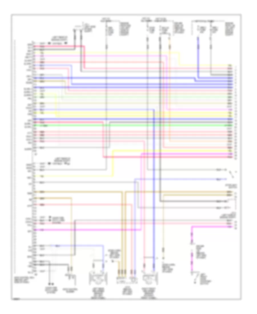
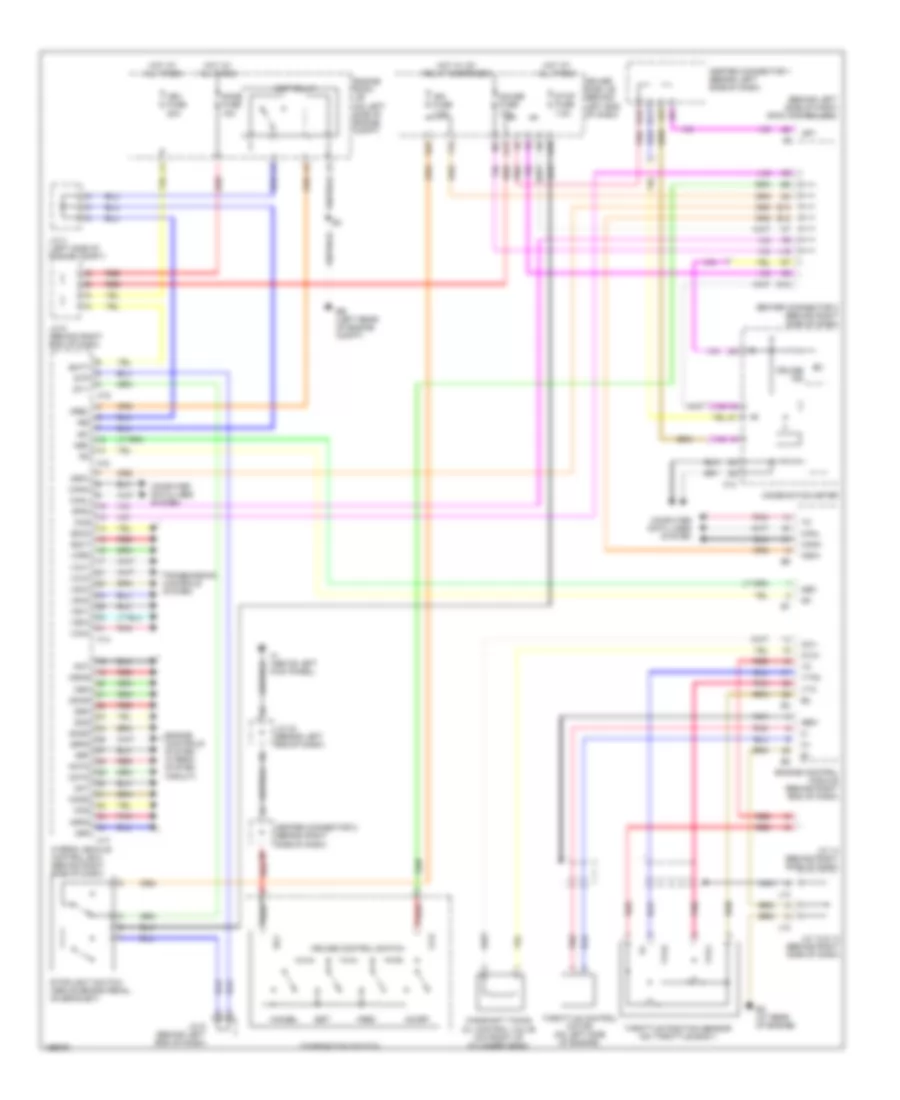
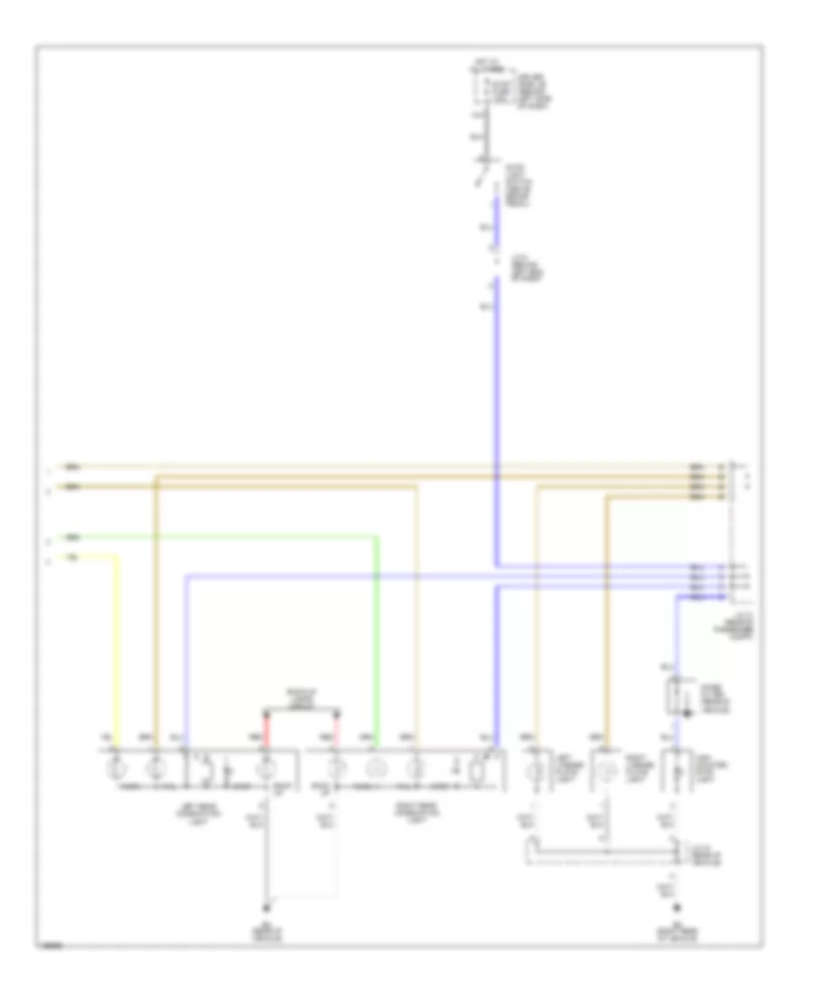
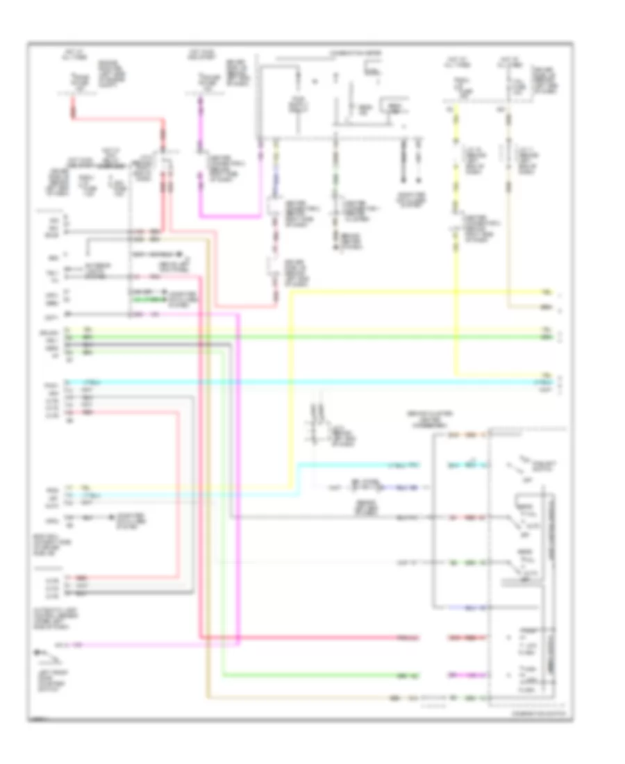
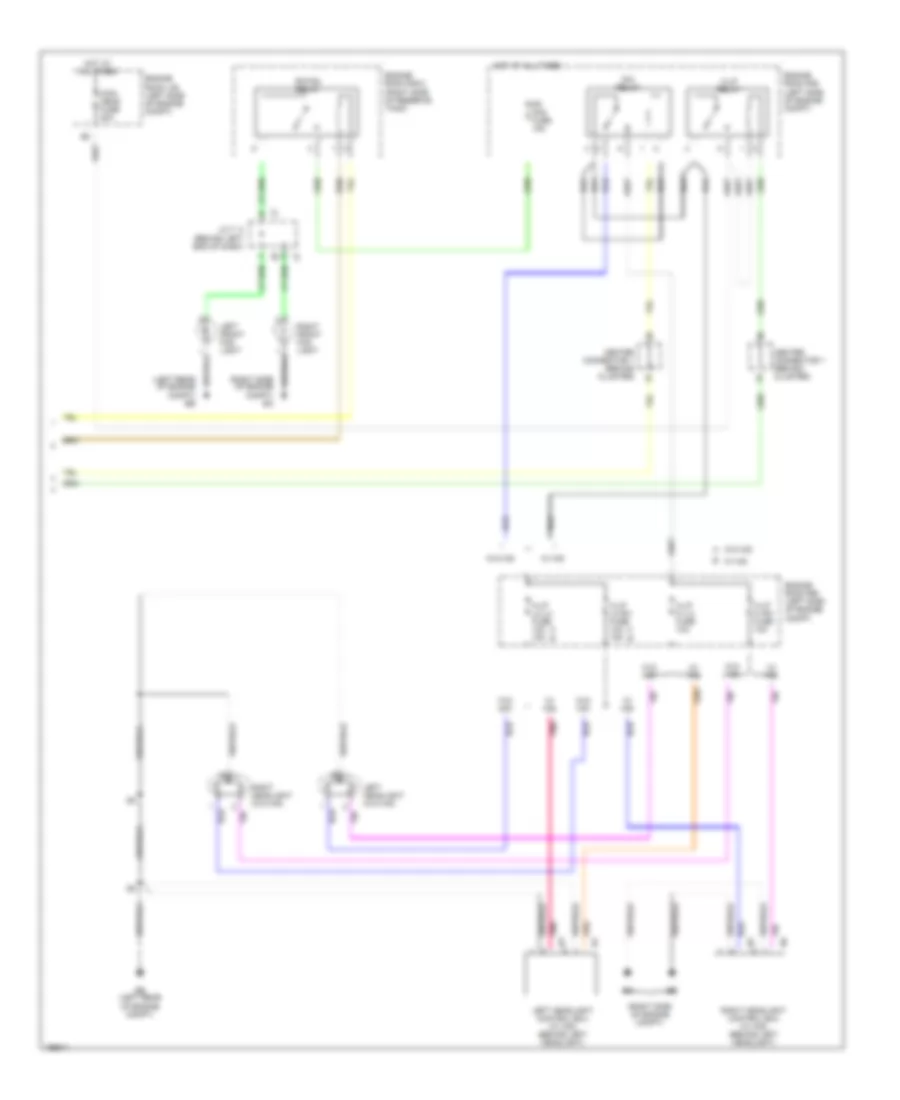
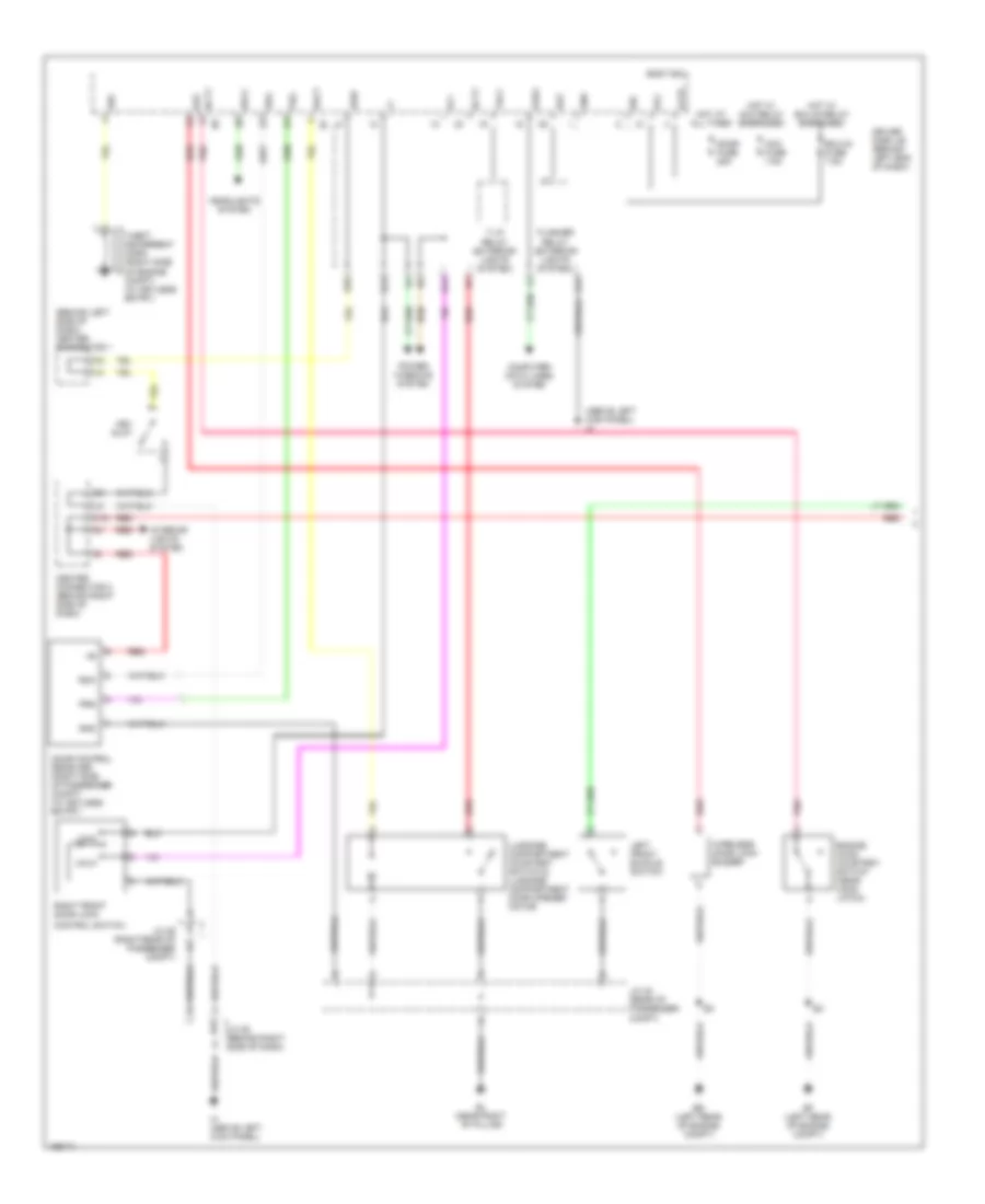
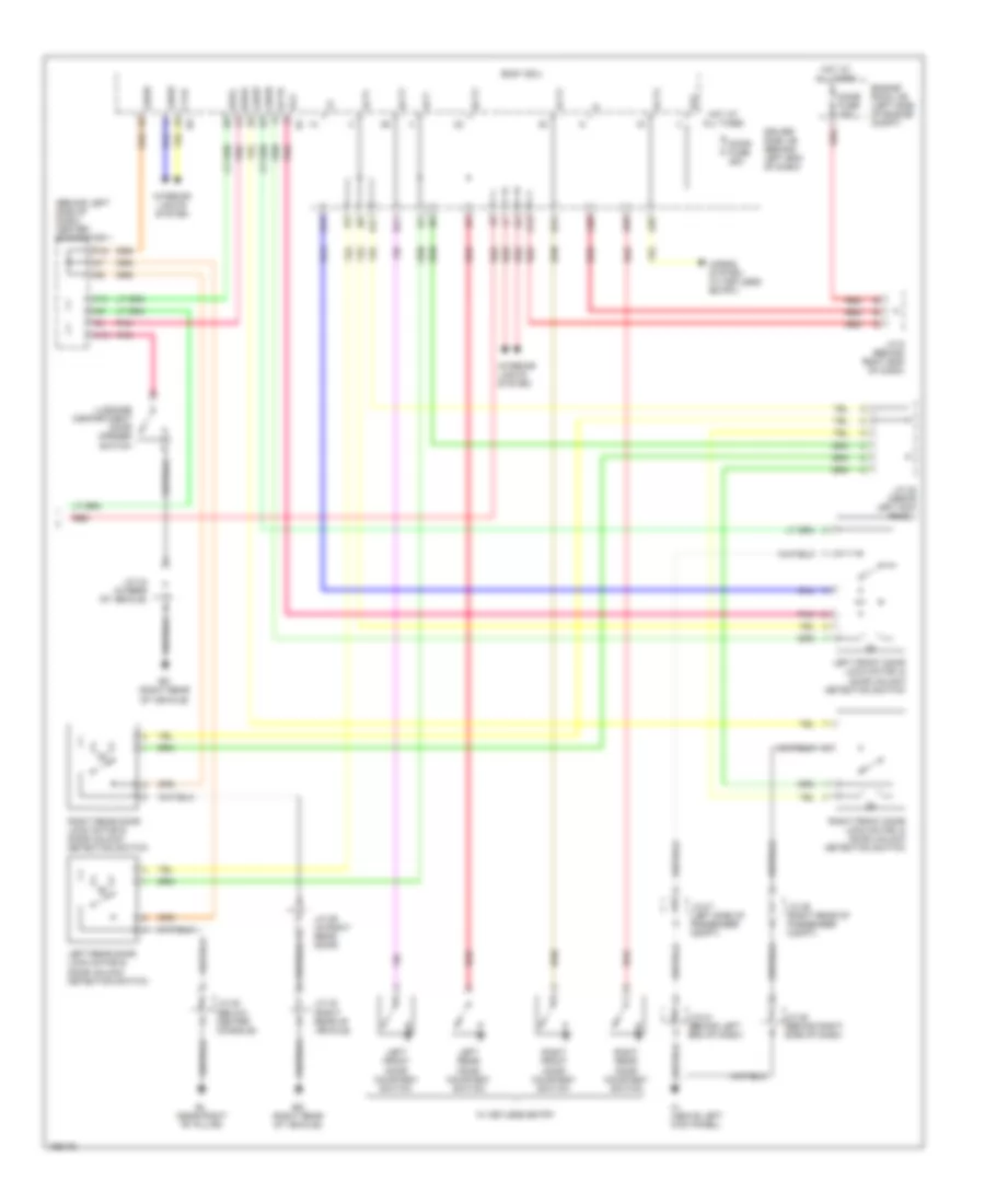
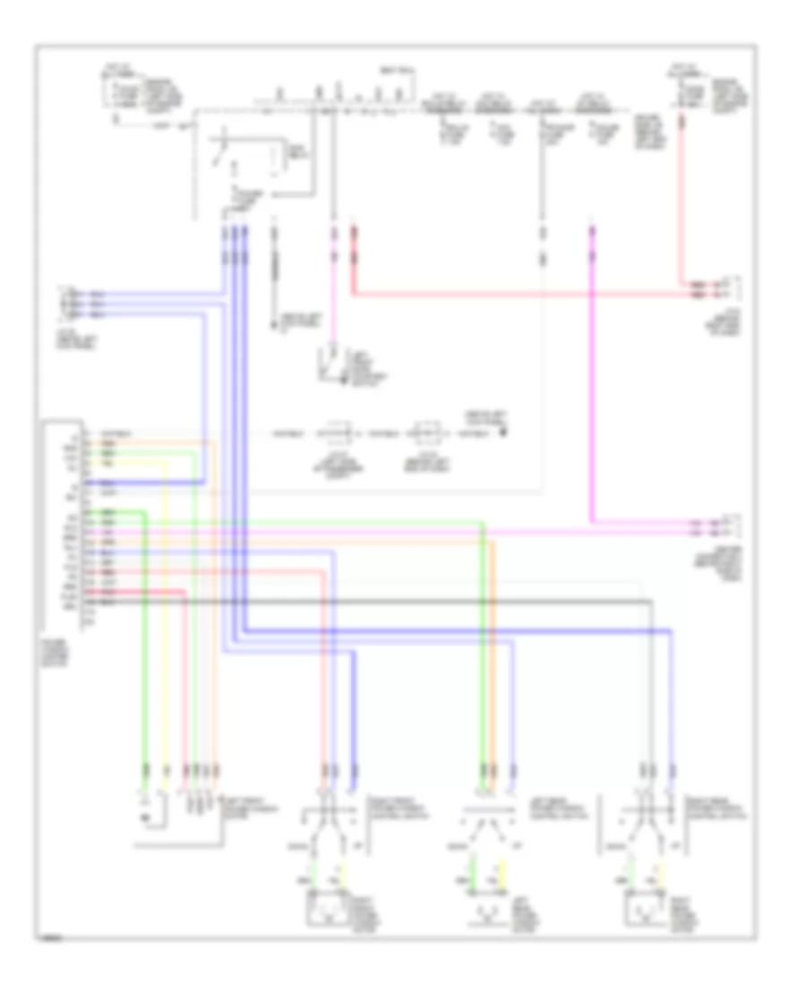
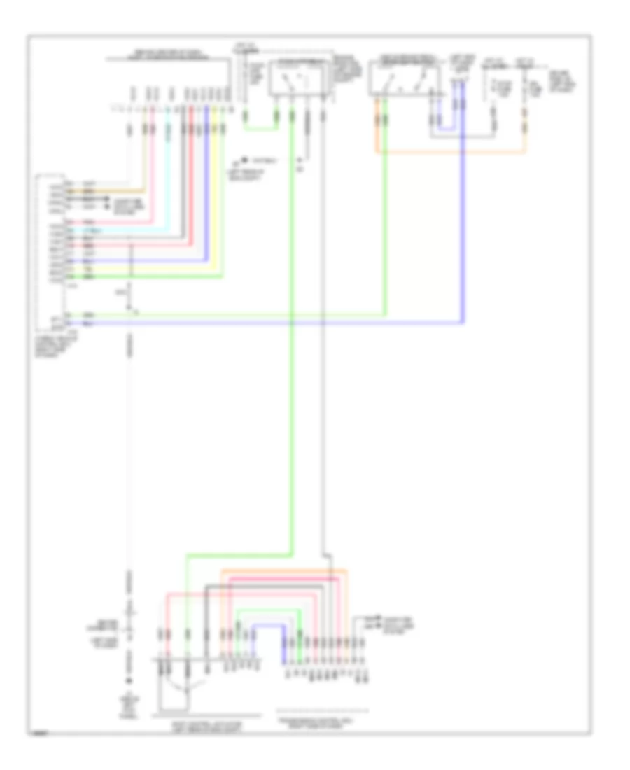
Automatic A/C Wiring Diagram (2 of 2) for Toyota Prius 2004
List of elements for Automatic A/C Wiring Diagram (2 of 2) for Toyota Prius 2004:
- (dash harn, right end of dash)
- A/c auto
- A/c condenser fan motor (left front of engine compt)
- A24
- Ambient temperature sensor (left front of vehicle)
- B14
- B15
- Canh
- Canl
- Cds fan fuse 30a
- Center connector (right i/p brace)
- Combination switch
- Compressor assembly (motor) (rear of engine)
- Computer data lines system
- Driver side j/b (behind left end of dash)
- Ea (right side of engine compt)
- Ecu-ig fuse 15aa
- Ee (left rear of engine compt)
- Engine control module (behind right end of dash)
- Engine coolant temperature sensor (rear of cylinder head)
- Engine room j/b (left side of engine compt)
- Engine room r/b (left side of engine compt)
- Engine room r/b 2 (right side of reserve tank)
- Fan
- Fan 1 relay
- Fan 2 relay
- Fan 3 relay
- Fr def
- Hot at all times
- Hot w/ ig on
- I11
- Inlet air
- Inverter (left rear of engine compt)
- J/c 10 (behind right side of dash)
- J/c 2
- J/c 4 (left side of engine compt)
- J/c 6 (behind right end of dash)
- J/c 9 (behind left end of dash)
- J14
- J15
- J16
- Pnk
- Pressure switch (right side of engine compt)
- Ps heater
- Ps htr relay
- Ptc heater (below right end of dash)
- Ptc htr 2 relay
- Ptc htr1 fuse 30a
- Ptc htr2 fuse 30a
- Radiator fan motor (behind radiator)
- Red
- Rr def
- Tam
- Temp+
- Temp-
- Thw
- Water temperature switch (right front of engine compt)
ANTI-LOCK BRAKES
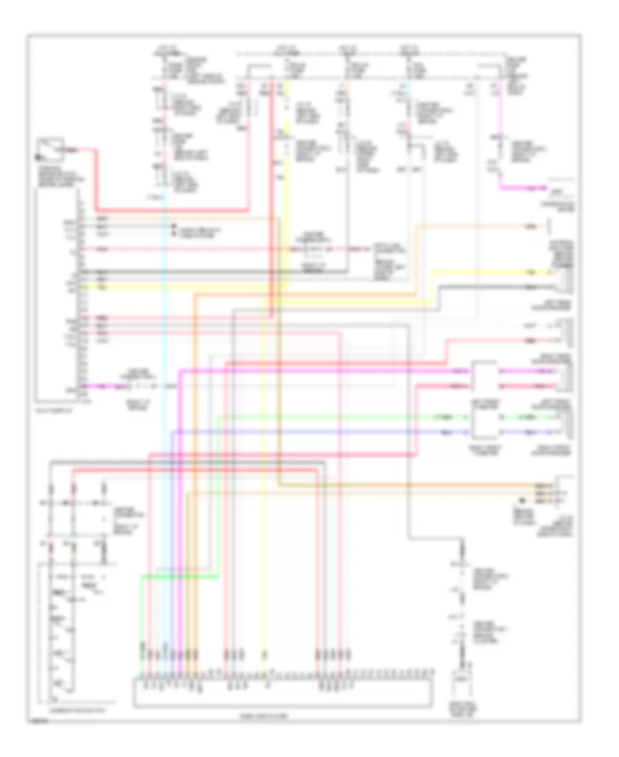
Anti-lock Brakes Wiring Diagram (1 of 5) for Toyota Prius 2004
List of elements for Anti-lock Brakes Wiring Diagram (1 of 5) for Toyota Prius 2004:
- (dash harn, behind left side of dash)
- (left rear of engine compt)
- +b01
- +bcty
- +bi1
- A18
- A24
- Abs 1 fuse 30a
- Abs 2 fuse 30a
- Abs main1 fuse 10a
- Bs1
- Can-h
- Can-l
- Computer data lines system
- D/g
- D21
- Driver side j/b (behind left end of dash)
- E3 e3
- Ecu-ig fuse 7.5a
- Ena
- Engine room j/b (on left side of engine compt)
- Engine room r/b (on left side of engine compt)
- Fail
- Fr+
- Fr-
- Gnd
- Gnd2
- Gnd3
- Hot at all times
- Hot in on and start
- Ig1
- J/c 1 (left side of eng compt)
- J/c 4 (left side of engine compt)
- J/c 9 (behind left end of dash)
- Left front door courtesy switch
- Left rear abs speed sensor (on left rear wheel)
- Mr1
- Mr1+
- Mtt
- Pacc
- Pck1
- Pfr
- Pmc1
- Pnk
- Prl
- R1+
- Red
- Right front abs speed sensor (on right front wheel)
- Rl+
- Rl-
- Rss
- Scss
- Sg1
- Skid control buzzer
- Skid control ecu (behind left side of dash)
- Slafr+
- Slafr-
- Slarl+
- Slarl-
- Slrfr+
- Slrfr-
- Slrrl+
- Slrrl-
- Smc1
- Sp1
- Sr1
- Stop fuse 7.5a
- Stoplight switch
- Stp
- Vbz
- Vcm1
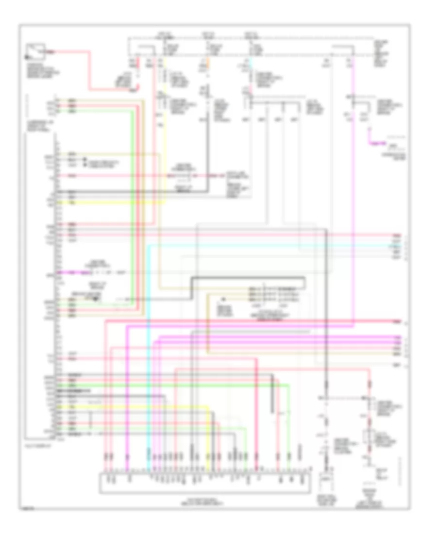
Anti-lock Brakes Wiring Diagram (2 of 5) for Toyota Prius 2004
List of elements for Anti-lock Brakes Wiring Diagram (2 of 5) for Toyota Prius 2004:
- Abs 1 relay
- Abs 2 relay
- Abs main3 fuse 15a
- Abs mtr 2 relay
- Abs mtr relay
- Bat
- Bcty
- Bq (right of rear vehicle)
- Canh
- Canl
- Center connector 2 (behind right side of dash)
- Computer data lines system
- Dcty
- Ena
- Engine room r/b (left side of engine compt)
- Fail
- Gnd
- H15
- Hot at all times
- Ih (above left kick panel)
- J/c 20 (behind upper right side of dash)
- J/c 23 (center console)
- J/c 24
- J/c 25
- J/c 6 (behind right end of dash)
- J/c 7, 8 (behind left end of dash)
- Out
- Out2
- Pnk
- Red
- Steering sensor (on steering column)
- Yaw rate sensor (below center console
Anti-lock Brakes Wiring Diagram (3 of 5) for Toyota Prius 2004
List of elements for Anti-lock Brakes Wiring Diagram (3 of 5) for Toyota Prius 2004:
- (behind left side of dash) brake master stroke simulator cylinder assembly
- (left rear of engine compt)
- Abs & ba & trac & vsc actuator (rear of engine compt)
- Abs fuse 30a
- Bcss
- Bm1
- Bm2
- Bs1
- Bs2
- Bsr
- Fl+
- Fl-
- Fr+
- Fr-
- Fuse holder
- Gnd1
- Gnd2
- J/c 1 (left side of eng compt)
- J/c 7, 8 (behind left end of dash)
- Mtt
- Nca
- Pacc
- Pck1
- Pck2
- Pfl
- Pfr
- Pmc1
- Pmc2
- Pnk
- Prl
- Prr
- Red
- Rl+
- Rl-
- Rr+
- Rr-
- S/c 2, 3
- S3 pnk
- Smc1
- Smc2
- Vcm1
- Vcm2
Anti-lock Brakes Wiring Diagram (4 of 5) for Toyota Prius 2004
List of elements for Anti-lock Brakes Wiring Diagram (4 of 5) for Toyota Prius 2004:
- (behind center of dash) ii
- (dash harn, behind left side of dash)
- (vfd)
- A13
- Abs ind
- Bean ic
- Brake cntrl ind
- Brake ind
- Center connector 1 (behind cluster)
- Center connector 2 (behind right side of dash)
- Combination meter
- Computer data lines system
- D11
- Dome fuse 15a
- Driver side j/b (behind left end of dash)
- Engine room r/b (left side of engine compt)
- Gauge fuse 10a
- H15
- H16
- Hot at all times
- Hot in on and start
- I1 (dash harn, behind left side of dash)
- I16
- J/c 6 (behind right end of dash)
- J/c 9 (behind left end of dash)
- L16
- Left front abs speed sensor (on left front wheel)
- Nca
- Pnk
- Red
- Right rear abs speed sensor (on right rear wheel)
- Slip ind
- Vsc ind
Anti-lock Brakes Wiring Diagram (5 of 5) for Toyota Prius 2004
List of elements for Anti-lock Brakes Wiring Diagram (5 of 5) for Toyota Prius 2004:
- (above brake pedal) brake pedal stroke sensor
- (base of parking brake lever) parking brake switch
- (behind left end of dash) j/c 9
- (right rear of engine compt) brake fluid level warning switch
- +b02
- +bi2
- Abs main2 fuse 10a
- Bs2
- Driver side j/b (behind left end of dash)
- Ea (right side of engine compt)
- Ee (left rear of engine compt)
- Engine room r/b (on left side of engine compt)
- Fl+
- Fl-
- Fss
- Gnd4
- Gnd5
- Gnd6
- Hot at all times
- Hot in on and start
- Ig2
- Ign fuse 7.5a
- Lbl
- Mr2
- Mr2+
- Nca
- Pck2
- Pfl
- Pkb
- Pmc2
- Pnk
- Prr
- R2+
- Red
- Rr+
- Rr-
- S10
- Sg2
- Skg
- Skid control ecu (behind left side of dash)
- Sks1
- Sks2
- Slafl+
- Slafl-
- Slarr+
- Slarr-
- Slrfl+
- Slrrr+
- Slrrr-
- Smc2
- Sr2
- Ssk
- Vcm2
- Vcsk
ANTI-THEFT
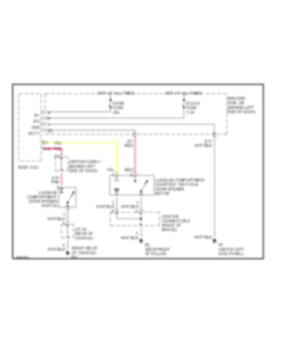
Forced Entry Wiring Diagram (1 of 2) for Toyota Prius 2004
List of elements for Forced Entry Wiring Diagram (1 of 2) for Toyota Prius 2004:
- (above left kick panel) ih
- (behind left side of dash) option connector (glass breakage sensor)
- +b1
- Acc
- Acc fuse 7.5a
- Altb
- Bact
- Bcty
- Bl (near right ``b" pillar)
- Body ecu
- Center connector 2 (behind right side of dash)
- Computer data lines system
- Door control receiver (right side of passenger compt) (w/o smart entry)
- Door fuse 25a
- Driver side j/b (behind left end of dash)
- E17
- Ecu-b fuse 15a
- Ecu-ig fuse 7.5a
- Ef (left rear of engine compt)
- Engine hood courtesy switch (near hood latch)
- Flasher relay (exterior lights system)
- Gbs
- Gnd
- H15
- H16
- Haz
- Hcty
- Headlights system
- Hot at all times
- Hot w/ acc relay energized
- Hot w/ ecu-ig relay energized
- Hrly
- Ih (above left kick panel)
- Interior lights system
- J/c 20 & 21 (behind upper right side of dash)
- J/c 23 (in center console)
- J/c 25 (behind right side of dash)
- J/c 30 (rear of passenger compt)
- J/c 9 (behind left end of dash)
- J20
- J21
- L12
- Luggage compartment courtesy switch & luggage compartment door opener motor
- Odb2
- Pnk
- Prg
- Rda
- Rda3
- Red
- Sec
- Sig
- Smart key ecu (behind left side of dash) (w/ smart entry)
- T-lp relay (exterior lights system)
- Theft deterrent horn (right side of engine compt)
- Trly
- W/ smart entry
- W/o smart entry
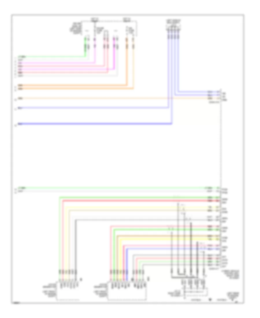
Forced Entry Wiring Diagram (2 of 2) for Toyota Prius 2004
List of elements for Forced Entry Wiring Diagram (2 of 2) for Toyota Prius 2004:
- (behind center of dash) ii
- (behind left side of dash) center connector 1
- A13
- A28
- A30
- Acc
- Act+
- Act-
- Actd
- Bean ic
- Bl (near right "b" pillar)
- Body ecu
- Bq (right rear of vehicle)
- Combination meter
- Computer data lines system
- D20
- D21
- D24
- Dcty
- Dome fuse 15a
- Door fuse 25a
- Driver side j/b (behind left end of dash)
- Engine room j/b (left side of engine compt)
- F15
- H15
- H17
- Horns system
- Hot at all times
- Ih (above left kick panel)
- Interior lights system
- J/c 22 (above left kick panel)
- J/c 24 (behind left end of dash)
- J/c 25 (behind right side of dash)
- J/c 26 (right rear of passenger compt)
- J/c 27 (left side of passenger compt)
- J/c 28 (below center console)
- J/c 29 (in right rear door)
- J/c 32 (right rear of vehicle)
- J/c 6 (behind right end of dash)
- Left front door courtesy switch
- Left front door lock motor, & door unlock detection switch
- Left rear door courtesy switch
- Left rear door lock motor & door unlock detection switch
- Lswd
- Lswp
- Lswr
- Pcty
- Rcty
- Red
- Right front door courtesy switch
- Right front door lock motor, & door unlock detection switch
- Right rear door courtesy switch
- Right rear door lock motor & door unlock detection switch
- Security
- Sind
Immobilizer Wiring Diagram for Toyota Prius 2004
List of elements for Immobilizer Wiring Diagram for Toyota Prius 2004:
- (behind right side of dash) center connector 2
- Acc
- Acc fuse 7.5a
- Agnd
- Am1
- Am1 fuse 7.5a
- Am2
- Am2 fuse 15a
- Body ecu
- Cdsw
- Center connector 1 (behind left side of dash)
- Code
- Cpub
- Cuws
- D11
- D12
- D13
- D14
- Driver side j/b (behind left end of dash)
- E10
- E11
- E13
- E26
- Engine room j/b (left side of engine compt)
- F11
- F15
- G10
- G11
- G13
- G14
- Gnd
- Gnd2
- H14
- Hev0
- Hev1
- Hot at all times
- Hot w/ acc relay energized
- Hot w/ ig2 relay energized
- Hybrid vehicle control ecu (behind right side of dash)
- I13
- I14
- Ign fuse 7.5a
- Igsw
- Ih (above left kick panel)
- Imp
- Inds
- Indw
- J/c 10 (behind right side of dash)
- J/c 25 (behind right side of dash)
- J10
- J11
- J12
- J13
- J14
- J15
- J16
- Key slot
- Ksw
- Lin1
- Mpx1
- Mpx2
- P con main fuse 7.5a
- Pnk
- Power source control ecu (behind left side of dash)
- Power switch
- Rdy
- Red
- Sol1
- Sol2
- Ssw1
- Ssw2
- St2
- Stsw
- Trans- ponder key coil
- Transmission control ecu (behind right side of dash)
- Transponder key amplifier
- Transponder key computer (behind upper left side of dash)
- Txct
- Vc5
BODY CONTROL MODULES
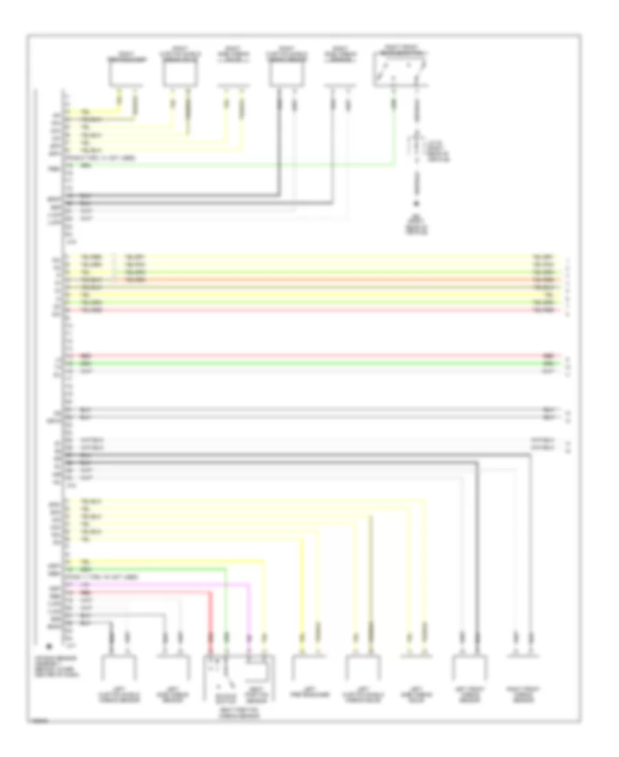
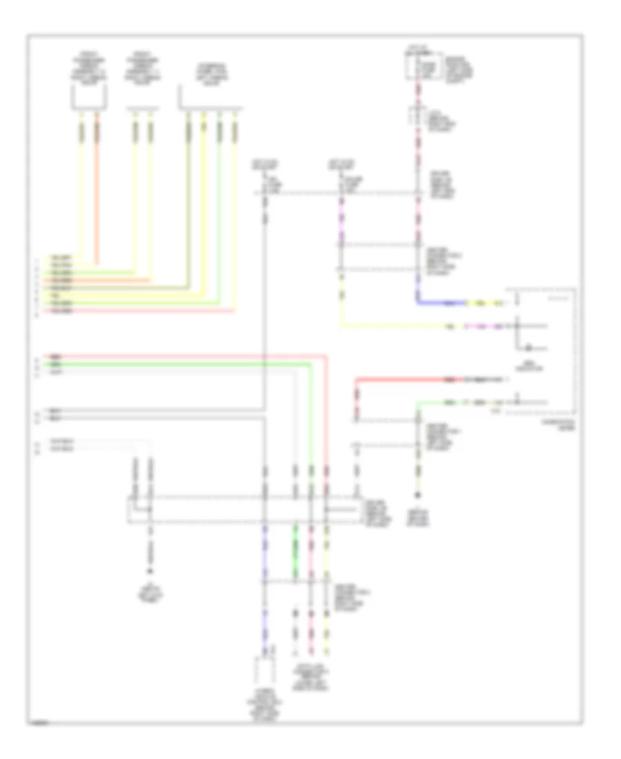
Body Control Modules Wiring Diagram for Toyota Prius 2004
List of elements for Body Control Modules Wiring Diagram for Toyota Prius 2004:
- (above left kick panel)
- (not used)
- (not used) red
- A26
- A28
- A30
- Acc
- Acc fuse 7.5a
- Acc on
- Act+
- Act-
- Actd
- All times
- Altb
- Anti-theft system
- Auto
- Bact
- Bcty
- Bdsu
- Body ecu (on driver side j/b)
- Buz
- Cltb
- Clte
- Clts
- Computer data lines system
- Cylb
- Cyld
- Cylp
- D18
- D20
- D21
- D22
- D24
- Dbkl
- Dcty
- Dome fuse 15a
- Door fuse 25a
- Door locks system
- Driver side j/b (behind left end of dash)
- Drl/dim
- E17
- E23
- E25
- E26
- E27
- E31
- Ecu-ig fuse 7.5a
- Ecub
- Engine room r/b (left side of engine compt)
- Exterior lights system
- F14
- Flasher relay
- Gbs
- Gnd
- H12
- H13
- H14
- H15
- H16
- H17
- H18
- Haz
- Hcty
- Head
- Headlights system
- Hon
- Horn
- Horn system
- Hot at
- Hot at all times
- Hot w/
- Hrly
- Ig on
- Ill
- Interior lights system
- J/c 6 (behind right end of dash)
- Kof
- Ksw
- Lswd
- Lswp
- Lswr
- Mpx1
- Mpx2
- Obd2
- Pcty
- Pmw1
- Pnk
- Power relay
- Prg
- Rcty
- Rda
- Red
- Sec
- Sig
- Sind
- T-lp relay
- Tail
- Trly
- Trunk tailgate fuel door system
- Ul1
- Ul3
- Warnings system
COMPUTER DATA LINES
Computer Data Lines Wiring Diagram (1 of 2) for Toyota Prius 2004
List of elements for Computer Data Lines Wiring Diagram (1 of 2) for Toyota Prius 2004:
- A/b
- Acc
- B11
- Bat
- Batt
- Battery ecu (above left rear wheelwell, near system main relay)
- Ca1h
- Ca1l
- Canh
- Canl
- D/g
- Data link connector (dlc) 3 (behind lower left side of dash)
- Engine control module (behind right end of dash)
- Gateway ecu (behind upper center of dash)
- Gnd
- Gtx+
- Gtx-
- H14
- Hybrid vehicle control ecu (behind right side of dash)
- Ih (above left kick panel)
- J/c 15 (behind left end of dash)
- J/c 16 (behind left end of dash)
- J/c 17 (at right kick panel)
- J/c 18 (at right kick panel)
- J/c 24 (behind left end of dash)
- J/c 25 (behind left end of dash)
- Mpd1
- Mpd2
- Nca
- Op3
- Pnk
- Power steering ecu (behind left side of dash)
- Sil
- Skid control ecu (behind left side of dash)
- Steering sensor (on steering column)
- Yaw rate sensor (below center console)
Computer Data Lines Wiring Diagram (2 of 2) for Toyota Prius 2004
List of elements for Computer Data Lines Wiring Diagram (2 of 2) for Toyota Prius 2004:
- A/c control assembly
- A18
- Acc fuse 7.5a
- Air bag sensor assembly (behind lower center of dash)
- Body ecu
- C10
- C11
- C12
- C13
- C14
- C16
- Center connector 1 (behind left side of dash)
- Center connector 2 (behind right side of dash)
- Combination meter
- D11
- D13
- Dbd2
- Driver side j/b (behind left end of dash)
- E13
- E31
- E32
- Ec (at rear of engine)
- Ecu-b fuse 15a
- Ecu-ig fuse 7.5a
- F10
- F11
- G10
- G13
- H11
- H12
- H13
- H15
- Headlight beam level control ecu (above right kick panel)
- Hot at all times
- Hot w/ acc relay energized
- Hot w/ ig1 relay energized
- I14
- J/c 19 (behind left end of dash)
- J13
- K10
- K11
- L14
- L16
- M10
- M11
- M12
- M13
- Mpx+
- Mpx-
- Mpx1
- Mpx2
- Mpx2+
- Multi-display
- N10
- N11
- Odb fuse 7.5a
- Pnk
- Power source control ecu (behind left side of dash)
- Prst
- Red
- S11
- Sil
- Smart key ecu (behind left side of dash)
- Transmission control ecu (behind right side of dash)
- Transponder key computer (behind upper left side of dash)
- Tx1+
- Tx1-
- W/ smart entry system
- W/o smart entry system
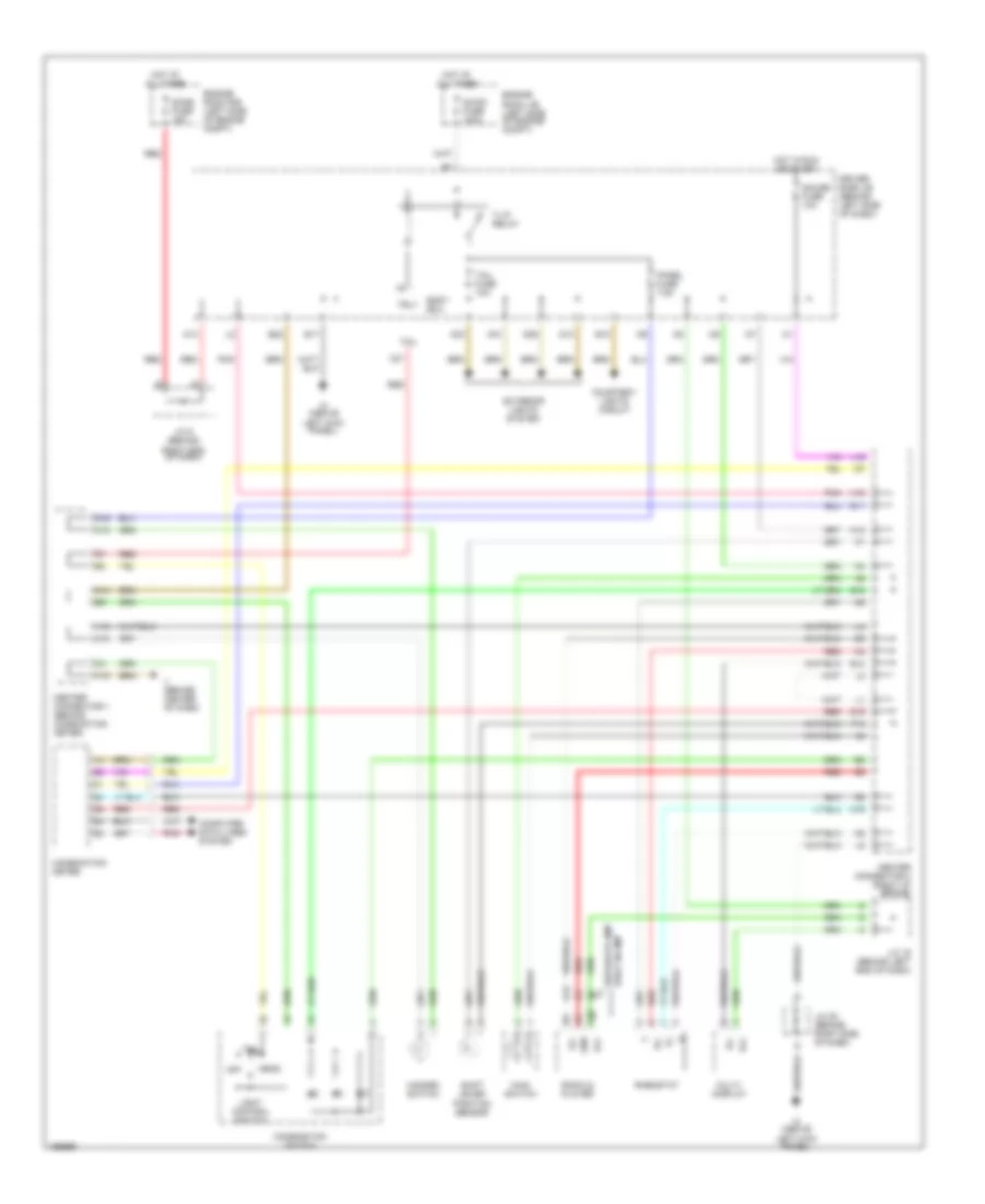
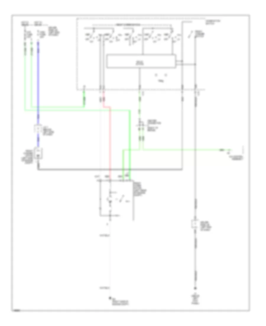
COOLING FAN
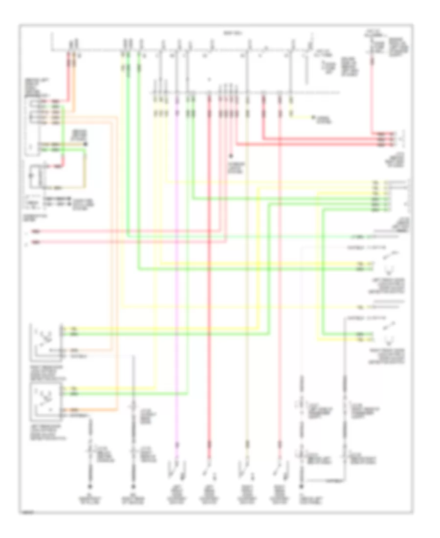
Cooling Fan Wiring Diagram for Toyota Prius 2004
List of elements for Cooling Fan Wiring Diagram for Toyota Prius 2004:
- (dash harn, right end of dash)
- A/c condenser fan motor (left front of engine compt)
- A/c control assembly
- A24
- Ambient temperature sensor (left front of vehicle)
- Canh
- Canl
- Cds fan fuse 30a
- Center connector (right i/p brace)
- Computer data lines system
- Driver side j/b (behind left end of dash)
- Ea (right side of engine compt)
- Ecu-ig fuse 15aa
- Ee (left rear of engine compt)
- Engine control module (behind right end of dash)
- Engine coolant temperature sensor (rear of cylinder head)
- Engine room j/b (left side of engine compt)
- Engine room r/b (left side of engine compt)
- Fan
- Fan 1 relay
- Fan 2 relay
- Fan 3 relay
- Hot at all times
- Hot w/ ig on
- J/c 10 (behind right side of dash)
- J/c 2
- J/c 4 (left side of engine compt)
- J/c 9 (behind left end of dash)
- Pressure switch (right side of engine compt)
- Radiator fan motor (behind radiator)
- Rdi fuse 30a
- Red
- Rf cf
- Tam
- Thw
- Water temperature switch (right front of engine compt)
CRUISE CONTROL
Cruise Control Wiring Diagram for Toyota Prius 2004
List of elements for Cruise Control Wiring Diagram for Toyota Prius 2004:
- (behind left side of dash) skid control ecu
- +b1
- +b2
- +res
- -set
- A13
- A18
- A27
- Batt
- C10
- Camshaft timing oil control valve (on front of cylinder head)
- Cancel
- Canh
- Canl
- Ccs
- Center connector 1 (behind left side of dash)
- Center connector 2 (behind right side of dash)
- Combination meter
- Combination switch
- Computer data lines system
- Cruise control switch
- Cruise ind
- D11
- D12
- Dome fuse 15a
- Driver side j/b (behind left end of dash)
- E12
- E13
- E2x1
- E2x2
- Ec (at rear of engine)
- Ecc
- Ee (left rear of engine compt)
- Engine control module (behind right end of dash)
- Engine controls system (hybrid system circuit)
- Engine room j/b (on left side of engine compt)
- F15
- Gauge fuse 10a
- Gcng
- Gcs
- Gcsg
- Ge01
- Grf
- Grfg
- Gsn
- H14
- H15
- H16
- H17
- Hev fuse 20a
- Hot at all times
- Hot w/ ig1 relay energized
- Hybrid vehicle control ecu (behind right side of dash)
- I16
- Igct relay
- Ign fuse 7.5a
- Igsw
- Ih (above left kick panel)
- J/c 12 & 13 (behind right side of dash)
- J/c 14 (behind right side of dash)
- J/c 24 (behind left end of dash)
- J/c 3 (left side of engine compt)
- J/c 6 (behind right end of dash)
- J/c 9 (behind left end of dash)
- J12
- J13
- L16
- Mcs
- Mcsg
- Mmt
- Mmtg
- Mrel
- Mrf
- Mrfg
- Msn
- Msng
- Nca
- Neo
- Ocv-
- Omt
- Omtg
- On/off
- Ovc+
- Pnk
- Red
- Sp1
- Spdi
- St1-
- Stop fuse 7.5a
- Stoplight switch (above brake pedal, on bracket)
- Stp
- Throttle control motor (on left side of engine)
- Throttle position sensor (on throttle body)
- Transmission controls system
- Vck4
- Vcr2
- Vcx1
- Vcx3
- Vsk4
- Vsx1
- Vsx2
- Vsx3
- Vta
- Vta1
- Vta2
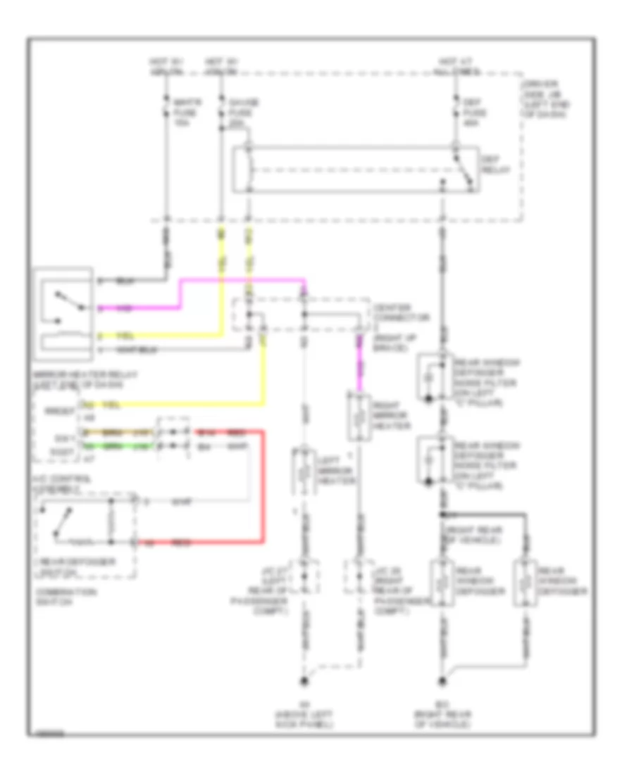
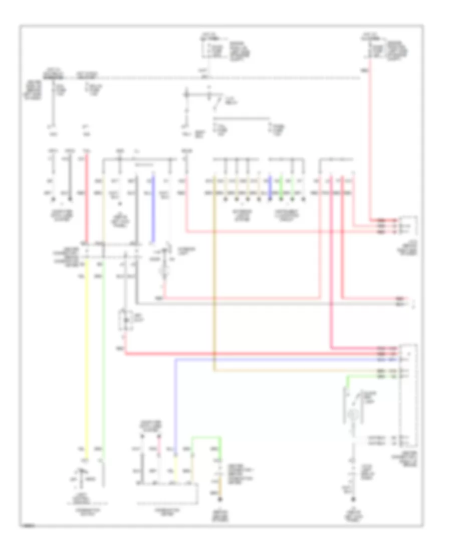
DEFOGGERS
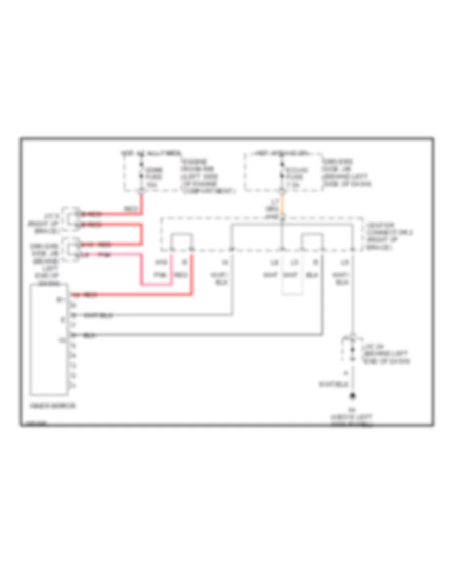
Defoggers Wiring Diagram for Toyota Prius 2004
List of elements for Defoggers Wiring Diagram for Toyota Prius 2004:
- A/c control assembly
- B14
- Bo (right rear of vehicle)
- Center connector (right i/p brace)
- Combination switch
- Def fuse 40a
- Def relay
- Driver side j/b (left end of dash)
- Gauge fuse 20a
- Hot at all times
- Hot w/ ign on
- Ih (above left kick panel)
- J/c 26 (right rear of passenger compt)
- J/c 27 (left rear of passenger compt)
- J15
- J16
- Left mirror heater
- M/htr fuse 15a
- Mirror heater relay (left end of dash)
- N10
- N12
- Rear defogger switch
- Rear window defogger
- Rear window defogger noise filter (on left "c" pillar)
- Red
- Right mirror heater
- Rrdef a8
- Sgst a7
- Sw1
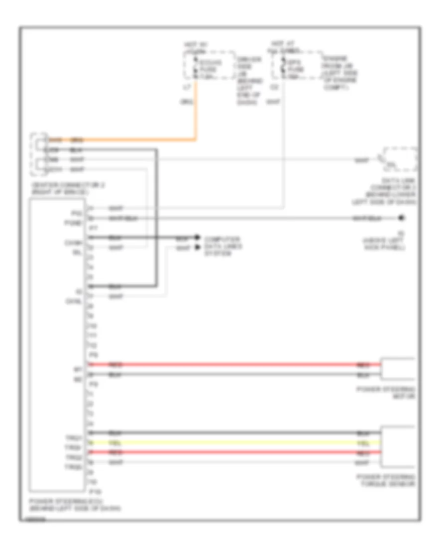
ELECTRONIC POWER STEERING
Electronic Power Steering Wiring Diagram for Toyota Prius 2004
List of elements for Electronic Power Steering Wiring Diagram for Toyota Prius 2004:
- C11
- Canh
- Canl
- Center connector 2 (right i/p brace)
- Computer data lines system
- Data link connector 3 (behind lower left side of dash)
- Driver side j/b (behind left end of dash)
- Ecu-ig fuse 7.5a
- Engine room j/b (left side of engine compt)
- Eps fuse 50a
- H15
- Hot at all times
- Hot w/ ig on
- Ig (above left kick panel)
- P10
- Pgnd
- Pig
- Power steering ecu (behind left side of dash)
- Power steering motor
- Power steering torque sensor
- Red
- Sil
- Trq1
- Trq2
- Trqg
- Trqv
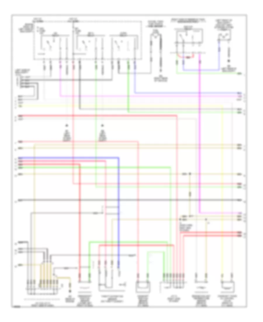
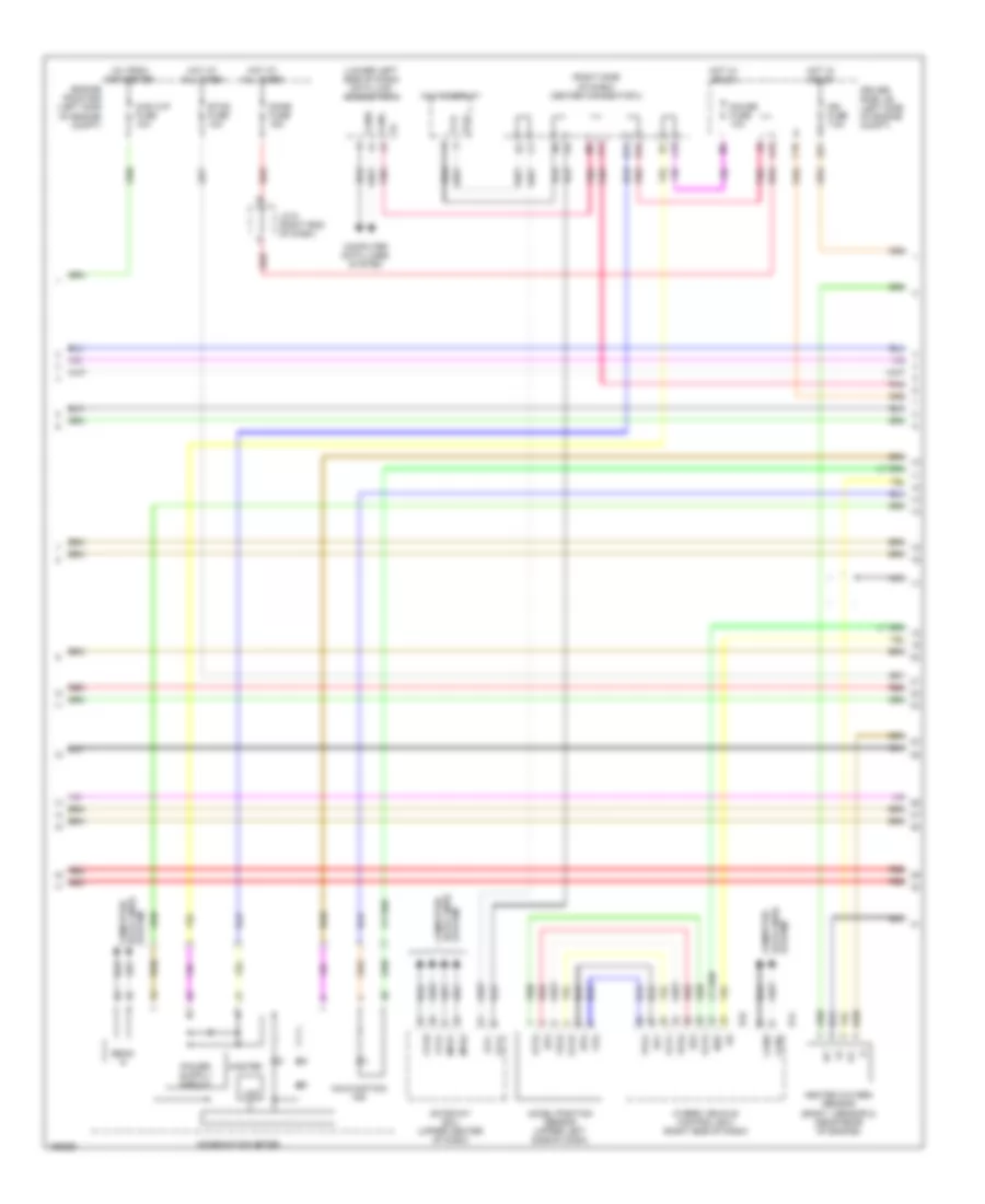
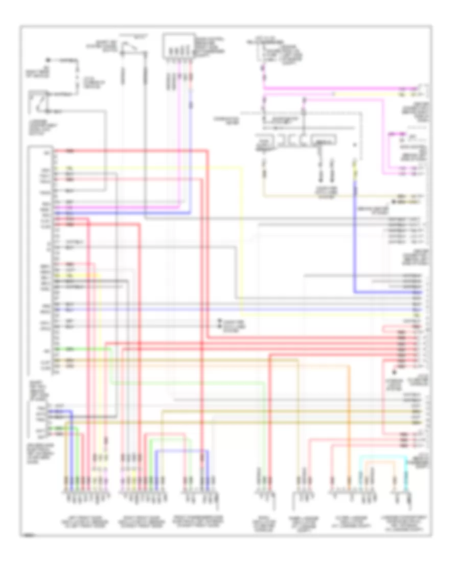
ENGINE PERFORMANCE
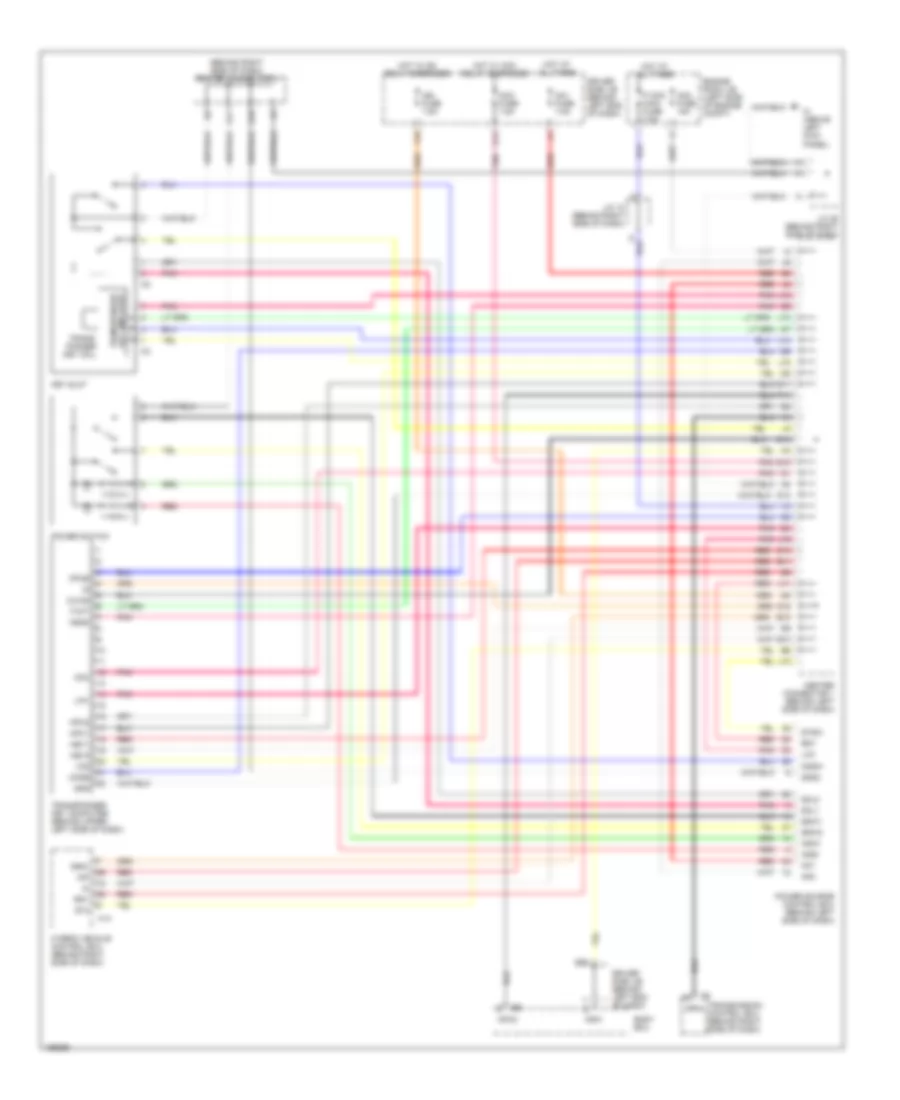
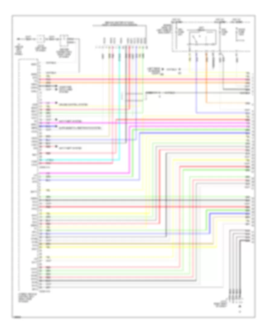
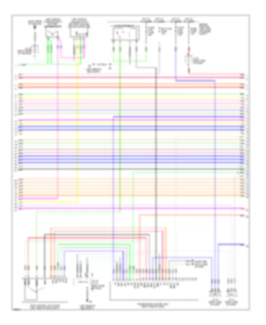
Hybrid System Wiring Diagram (1 of 7) for Toyota Prius 2004
List of elements for Hybrid System Wiring Diagram (1 of 7) for Toyota Prius 2004:
- (behind center of dash) shift lever position sensor
- (left rear of engine compt)
- Abfs
- Am2 fuse 15a
- Anti-theft system
- Batt
- Canh
- Canl
- Ccs
- Center connector 2 (right side of dash)
- Computer data lines system
- Conn h14
- Conn h15
- Cruise control system
- Dc/dc fuse 100a
- E2x1
- E2x2
- Engine room j/b (left side of eng compt)
- F12
- F13
- Gfiv
- Gimv
- Giva
- Givb
- Givt
- Giwa
- Giwb
- Gnd1
- Gnd2
- Gsdn
- Guu
- Gvu
- Gwu
- Hev fuse 20a
- Hot at all times
- Hybrid vehicle control ecu (right side of dash)
- Igct relay
- Igsw
- Ih (above left kick panel)
- Ilk
- Imi
- Imo
- J/c 24 (left end of dash)
- J/c 5 (right end of dash)
- Mfiv
- Miva
- Mivb
- Mivt
- Miwa
- Miwb
- Msdn
- Muu
- Mvu
- Mwu
- Nca
- Ovh
- Pnk
- Rdy
- Red
- Spd1
- St1-
- St2
- Stp
- Vcx1
- Vcx2
- Vcx3
- Vcx4
- Vsx2
- Vsx3
- Vsx4
- Vxs1
- Vxs4
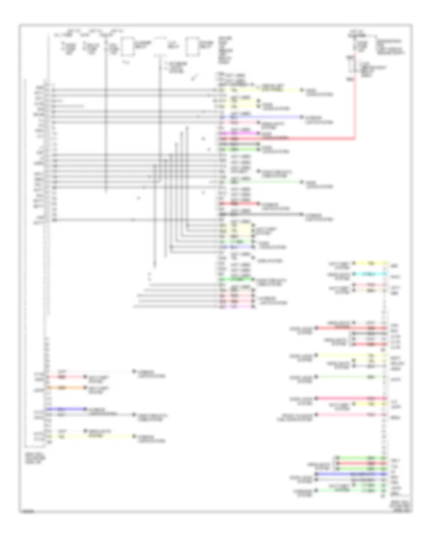
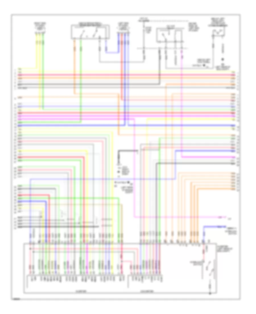
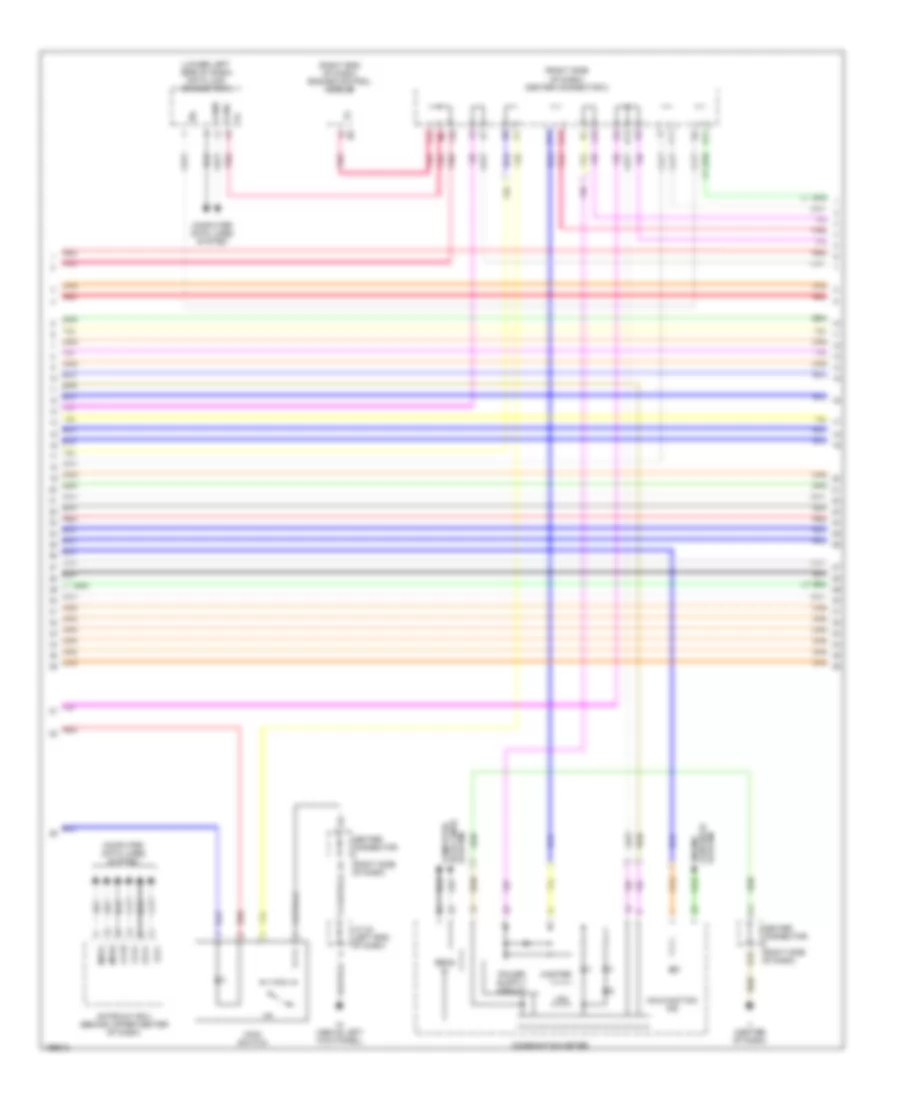
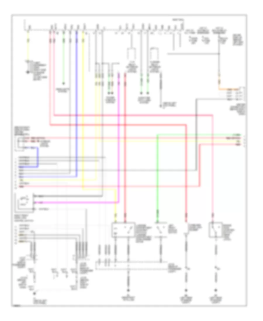
Hybrid System Wiring Diagram (2 of 7) for Toyota Prius 2004
List of elements for Hybrid System Wiring Diagram (2 of 7) for Toyota Prius 2004:
- (above brake pedal) stoplight switch
- (above left kick panel)
- (below left headlight) water pump motor (inverter)
- (left end of dash) j/c 9
- (left rear of engine compt)
- (right end of dash) j/c 6
- A10
- A11
- A18
- Converter
- Cpwm
- Csdn
- Driver side j/b (left end of dash)
- E17
- Ee (left rear of eng compt)
- Fcv
- Gcnv
- Gfiv
- Gimv
- Giva
- Givb
- Givt
- Giwa
- Giwb
- Gnd
- Gsdn
- Guu
- Gvu
- Gwu
- Hot at all times
- I10
- I12 +
- I13 -
- I14 w
- I15 w
- I16 cvsw
- Igct
- Ilk
- Interlock switch
- Inv w/p relay
- Inverter
- Inverter (left rear of eng compt)
- Irtn
- J/c 5 (right end of dash)
- Mfiv
- Miva
- Mivb
- Mivt
- Miwa
- Miwb
- Msdn
- Muu
- Mvu
- Mwu
- Nca
- Ovh
- Ovl
- Pnk
- Red
- Stop fuse 7.5a
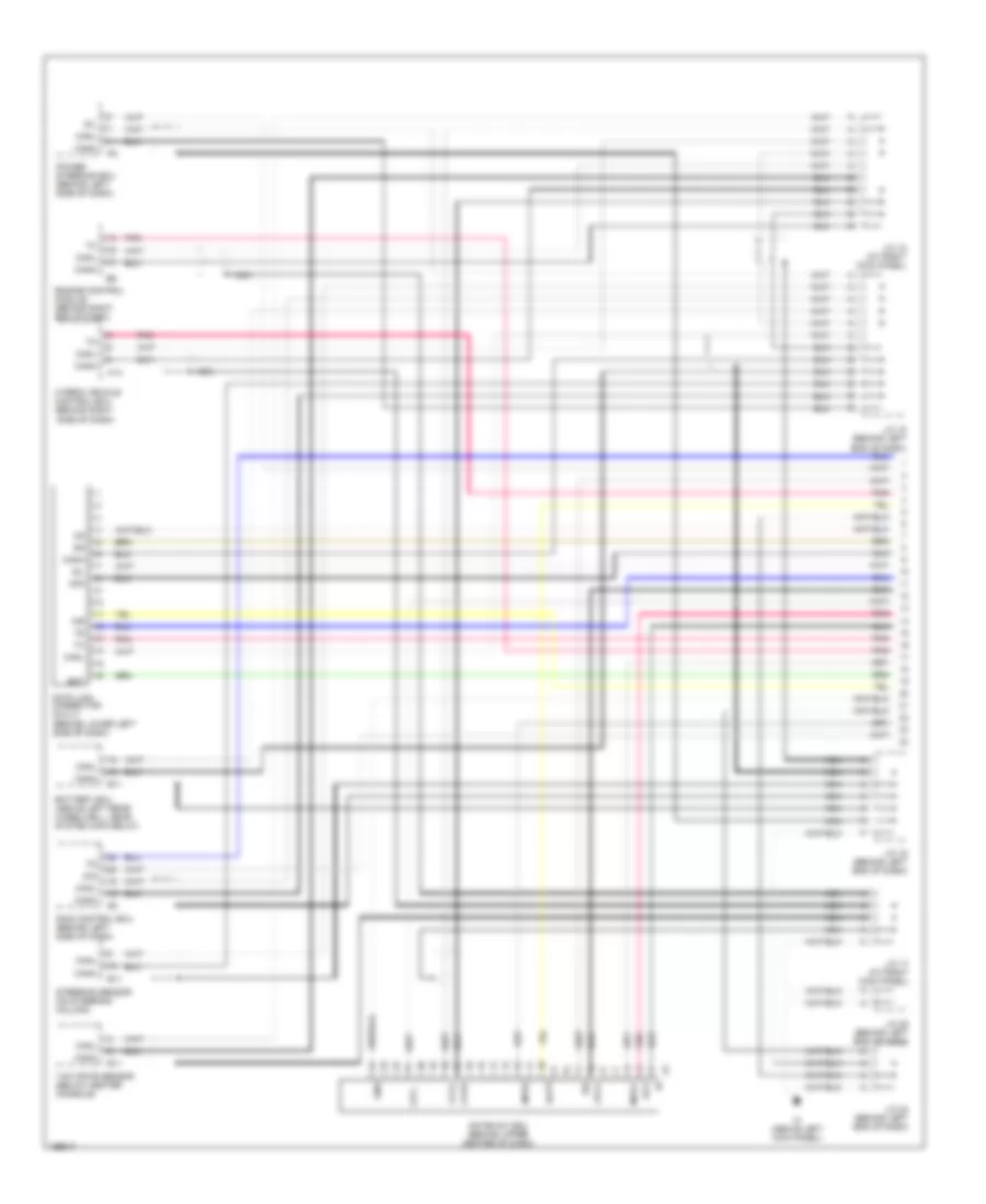
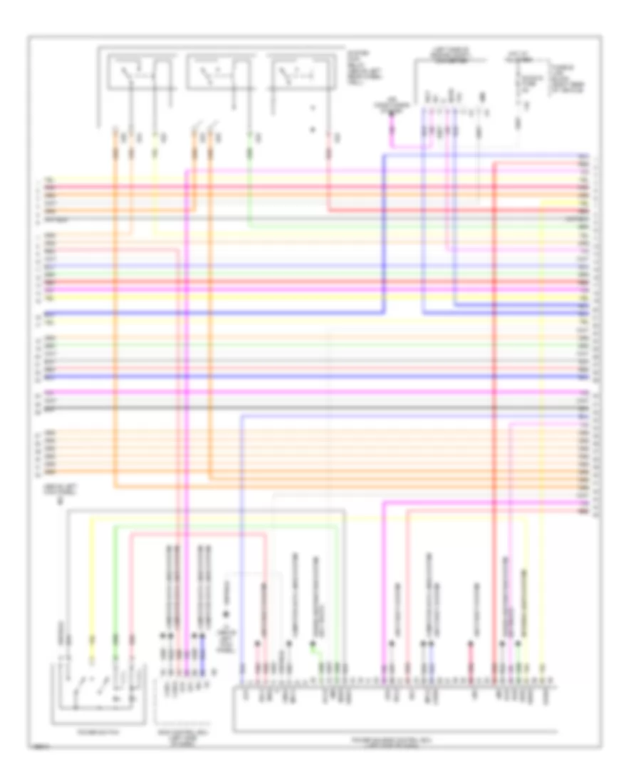
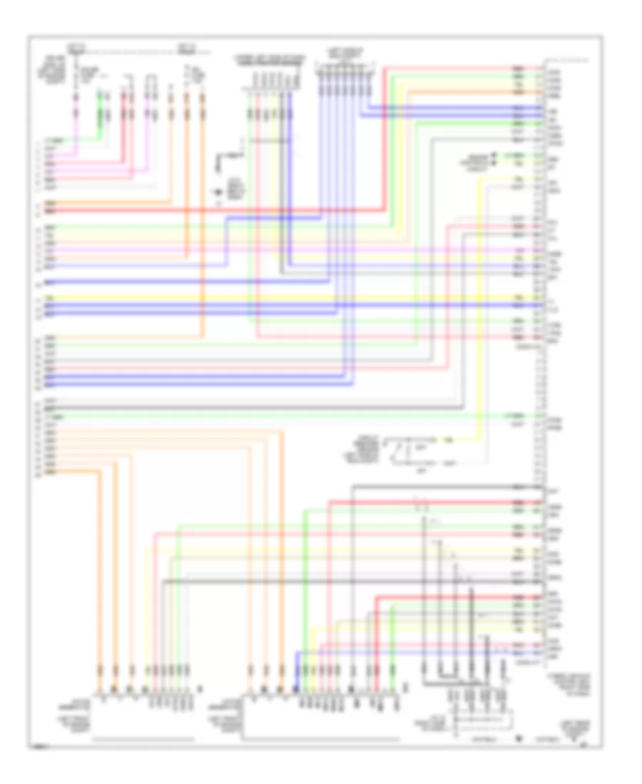
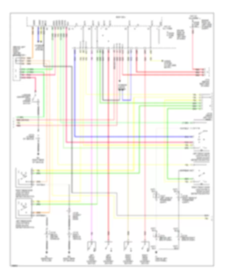
Hybrid System Wiring Diagram (3 of 7) for Toyota Prius 2004
List of elements for Hybrid System Wiring Diagram (3 of 7) for Toyota Prius 2004:
- (above left kick panel) ih
- (left side of engine compt) converter
- Accd
- Air conditioning system
- Am1
- Am2
- Amd
- Anti-theft system
- Can-h
- Can-l
- Cdsw
- Computer data lines system
- D/g
- Dc/dc-s fuse 5a
- F16
- Fusible link block (right rear of vehicle)
- Gnd2
- Hot at all times
- Id1
- Ig1d
- Ig2d
- Igct
- Ih (above left kick panel)
- Inds
- Indw
- Interior lights system
- Lin1
- Mpx1
- Mpx2
- Nodd
- Pnk
- Power distribution system (acc relay)
- Power distribution system (ig1 relay)
- Power source control ecu (left side of dash)
- Power switch
- Rdy
- Red
- S22
- S23
- S24
- S25
- S26
- S8 ts
- Skid control ecu (left side of dash)
- Sol1
- Sol2
- Sp1
- Spd
- Ssw1
- Ssw2
- Stp
- Stsw
- Swil
- System main relay (above left rear wheel- well)
- Vlo
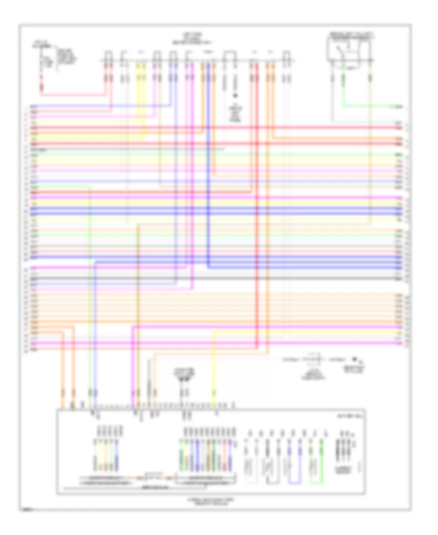
Hybrid System Wiring Diagram (4 of 7) for Toyota Prius 2004
List of elements for Hybrid System Wiring Diagram (4 of 7) for Toyota Prius 2004:
- (behind left taillight) battery fan relay
- (left side of dash) center connector 1
- (near right "b" pillar)
- Am1 fuse 7.5a
- B11
- Battery ecu
- Busbar module 1
- Busbar module 2
- Canh
- Canl
- Computer data lines system
- Current sensor
- Driver side j/b (left end of dash)
- E13
- E14
- Fctl1
- Gb1
- Gb2
- Gb3
- Gbb0 b12
- Gc1
- Gib
- Gnd
- H20
- H21
- Hot at all times
- Hybrid vehicle battery
- Hybrid vehicle battery (rear of vehicle)
- I16
- Ib b13
- Ig2
- Igct
- Ih (above left kick panel)
- J/c 30 (rear of pass compt)
- J10
- J11
- Nca
- Pnk
- Red
- Service plug
- Tb1
- Tb2
- Tb3
- Tc1
- Vbb1
- Vbb10
- Vbb11
- Vbb12
- Vbb13
- Vbb14
- Vbb2
- Vbb3
- Vbb4
- Vbb5
- Vbb6
- Vbb7
- Vbb8
- Vbb9
- Vib
Hybrid System Wiring Diagram (5 of 7) for Toyota Prius 2004
List of elements for Hybrid System Wiring Diagram (5 of 7) for Toyota Prius 2004:
- (left rear of eng compt)
- (left side of luggage compt) battery blower motor
- (left side of luggage compt) battery blower motor controller
- (right rear of vehicle) bq
- Batt
- Batt fan fuse 10a
- Bma
- Computer data lines system
- Dome fuse 15a
- E01
- E02
- Engine room r/b (left side of engine compt)
- Gnd
- Hot at all times
- Ind
- J/c 10 (right side of dash)
- J/c 14 (right side of dash)
- J/c 32 (right rear of vehicle)
- J/c 6 (right end of dash)
- J12
- J12 j/c 12, j/c 13 (right side of dash)
- J13
- Mgna
- Mpx1
- Mpx2
- Mua
- Mva
- Mwa
- P con main fuse 7.5a
- P con mtr fuse 30a
- P con mtr relay
- Pcon
- Pnk
- Ppos
- Re2
- Red
- Rvc
- Rz1
- Shift control actuator (left rear of eng compt)
- Sil
- Transmission control ecu (right side of dash)
Hybrid System Wiring Diagram (6 of 7) for Toyota Prius 2004
List of elements for Hybrid System Wiring Diagram (6 of 7) for Toyota Prius 2004:
- (lower left side of dash) data link connector 3
- (right end of dash) engine control module
- (right side of dash) center connector 2
- Bean ic
- Ca1h
- Ca1l
- Canh
- Canl
- Center connector (right side of dash)
- Combination meter
- Computer data lines system
- Controls system
- D11
- D12
- Engine
- F10
- F11
- Gateway ecu (behind upper center of dash)
- Gtx+
- Gtx-
- H11
- H15
- H16
- Ih (above left kick panel)
- Ii (center of dash)
- J/c 24 (left end of dash)
- K11
- L16
- Main switch
- Malfunction ind
- Master
- Mpd1
- Mpd2
- Pnk
- Red
- Sil
- Tc e6
- Vfd
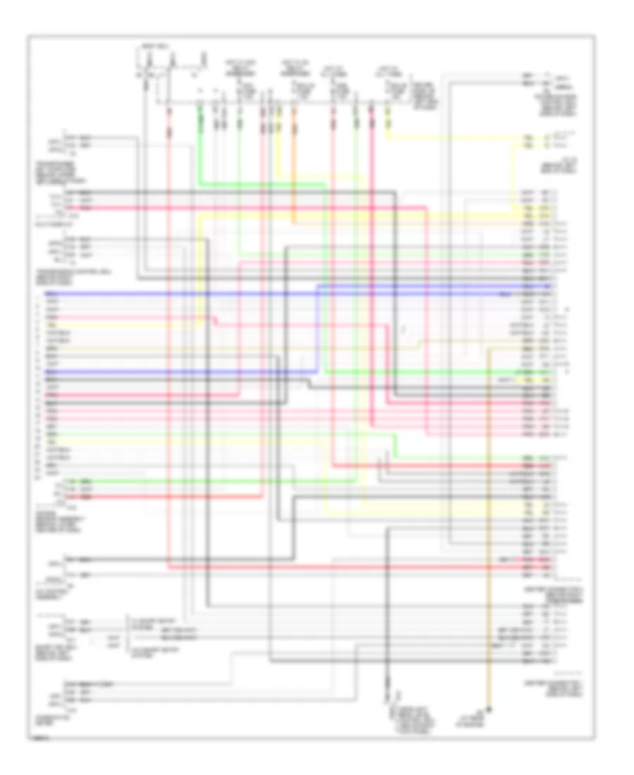
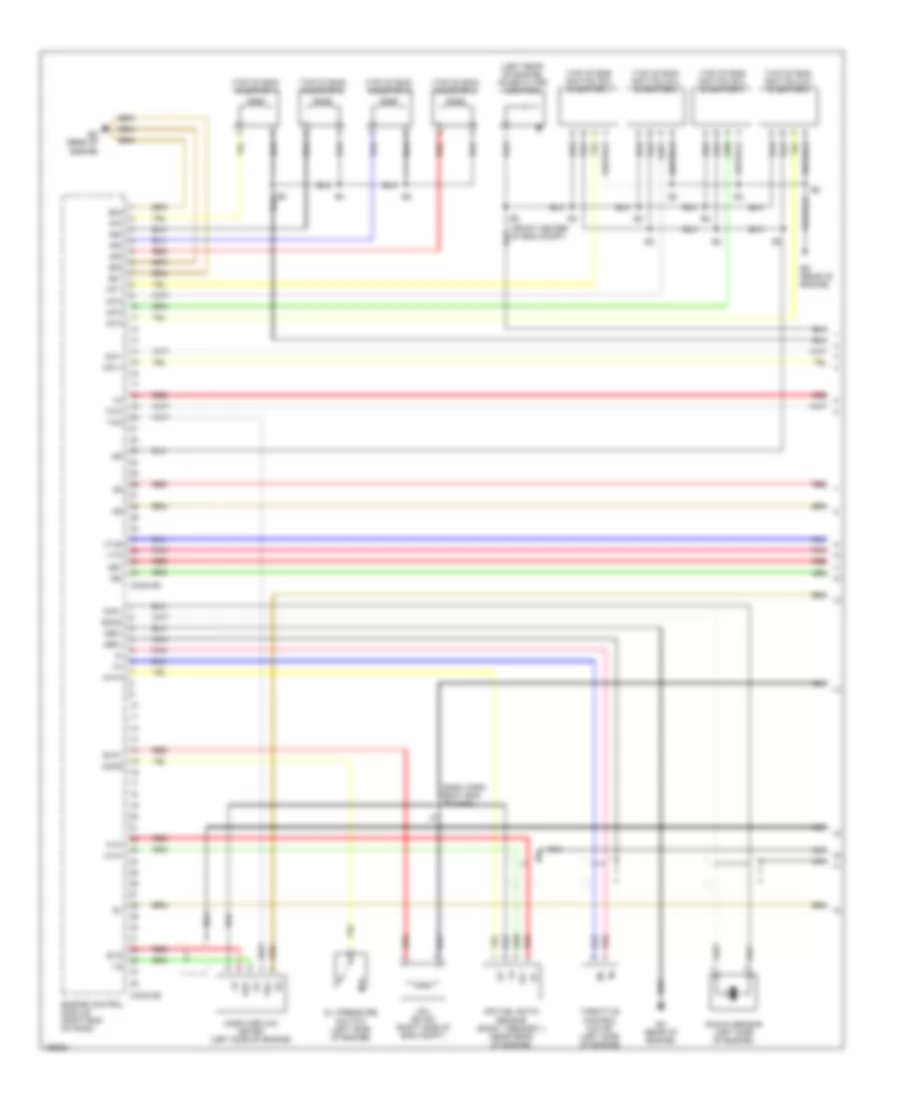
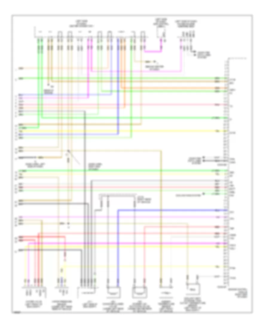
Hybrid System Wiring Diagram (7 of 7) for Toyota Prius 2004
List of elements for Hybrid System Wiring Diagram (7 of 7) for Toyota Prius 2004:
- (left rear of engine compt)
- (left side of eng compt) j/c 3
- (upper left side of dash) accel position sensor
- +b1
- +b2
- A13
- A27
- As1
- Asig
- Circuit breaker sensor (left side of eng compt)
- Con1
- Con2
- Con3
- Conn h16
- Conn h17
- Cpwm
- Csdn
- Driver side j/b (left side of engine compt)
- E21
- Engine controls circuit
- Ep1
- Ep2
- Epa
- Epa2
- F15
- Fcv
- Gauge fuse 10a
- Gcnv
- Gcs
- Gcsg
- Grf
- Grfg
- Gsn
- Gsng
- Hot w/ ign on
- Hybrid vehicle control ecu (right side of dash)
- Ign fuse 7.5a
- J/c 12 (right side of dash)
- J/c 5 (right end of dash)
- M10 omtg
- M2 u
- M3 v
- M4 w
- M5 grfg
- M6 u
- M7 v
- M8 w
- M9 mcsg
- Mcs
- Mcsg
- Mmt
- Mmtg
- Motor generator (left front of engine compt)
- Mrel
- Mrf
- Mrfg
- Msn
- Msng
- Nca
- Neo
- Nodd
- Omt
- Omtg
- Ovl
- Pcon
- Pnk
- Ppos
- Red
- Sif+
- Sif-
- Vcp2
- Vcpa
- Vlo
- Vpa
- Vpa1
- Vpa2
1.5L
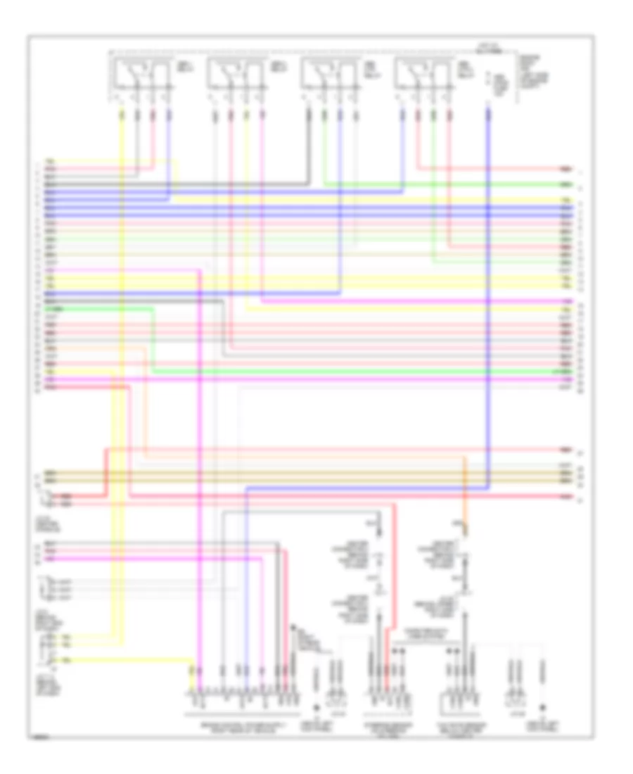
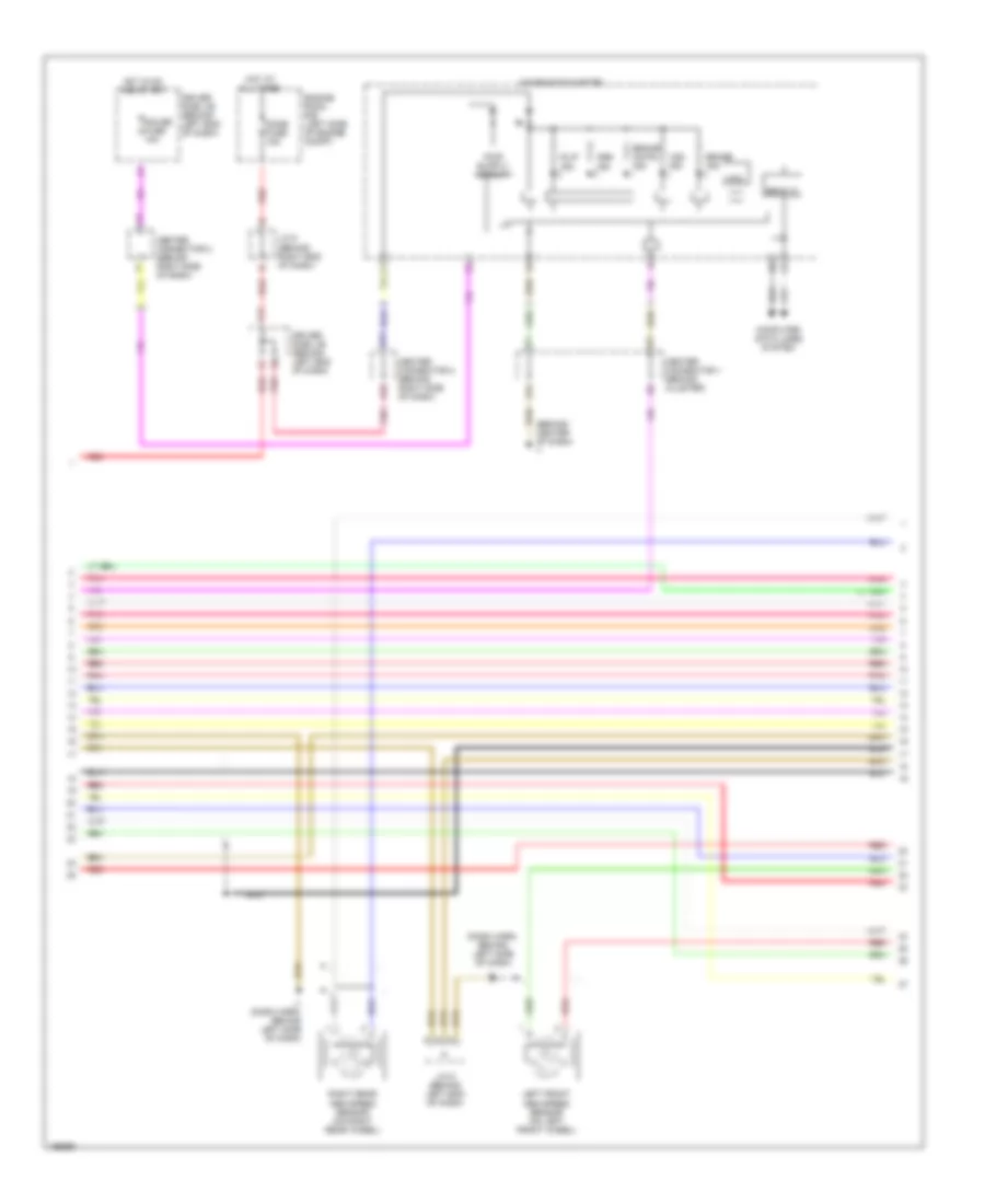
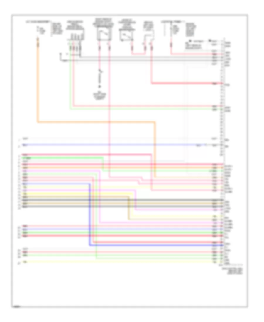
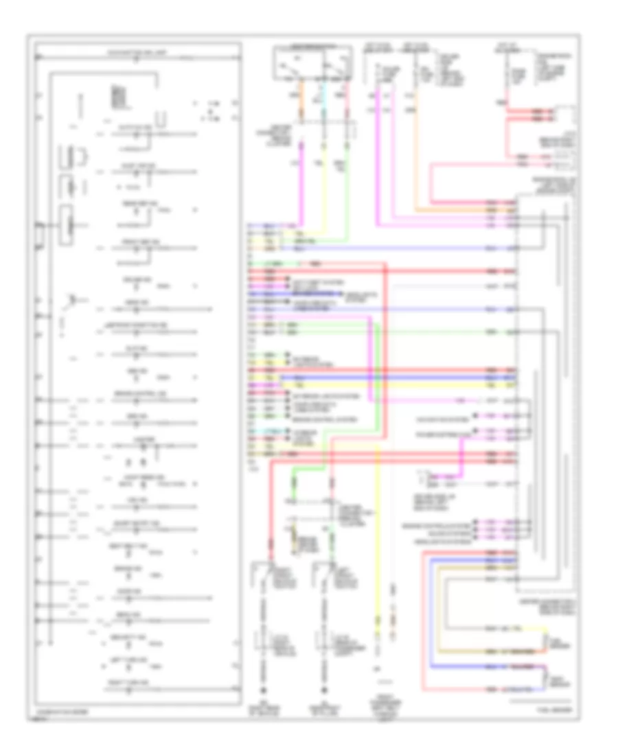
1.5L, Engine Controls Wiring Diagram (1 of 4) for Toyota Prius 2004
List of elements for 1.5L, Engine Controls Wiring Diagram (1 of 4) for Toyota Prius 2004:
- #10
- #20
- #30
- #40
- (dash harn, right end of dash)
- (left rear of engine) noise filter (ignition)
- (top of eng) ignition coil & ignitor 1
- (top of eng) ignition coil & ignitor 2
- (top of eng) ignition coil & ignitor 3
- (top of eng) ignition coil & ignitor 4
- (top of eng) injector 1
- (top of eng) injector 2
- (top of eng) injector 3
- (top of eng) injector 4
- A1a+
- A1a-
- Af+
- Af-
- Air fuel ratio sensor (bank 1 sensor 1) (near rear of engine)
- Conn e4
- Conn e5
- E01
- E02
- E04
- E2g
- Ec (rear of engine)
- Ed (rear of engine)
- Eknk
- Engine control module (right end of dash)
- Evg
- Evp1
- Ge01
- Ha1a
- Igf
- Igt1
- Igt2
- Igt3
- Igt4
- Knk1
- Knock sensor (left side of engine)
- Mass airflow meter (left side of engine)
- Me01
- Mops
- Nca
- Ne+
- Ne-
- Ocv+
- Ocv-
- Oil pressure switch (left side of engine)
- Pnk
- Red
- Tha
- Throttle control motor (left side of engine)
- Thw
- Vsv (evap) (right side of eng compt)
- Vta
- Vta2
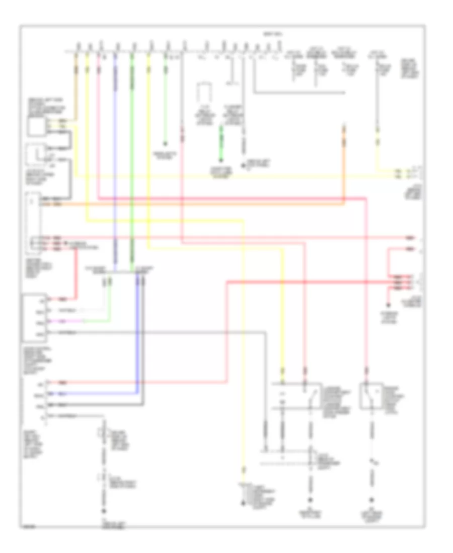
1.5L, Engine Controls Wiring Diagram (2 of 4) for Toyota Prius 2004
List of elements for 1.5L, Engine Controls Wiring Diagram (2 of 4) for Toyota Prius 2004:
- (in fuel tank) fuel pump & fuel sender
- (left front of eng compt) coolant heat storage water pump
- (left side of eng compt) j/c 2
- (right side of reserve tank) engine room r/b 2
- Am2 fuse 15a
- Bq (right rear of vehicle)
- C/opn relay
- Camshaft position sensor (rear of cyl head)
- Camshaft timing oil control valve (front of cyl head)
- Chs w/p relay
- Crankshaft position sensor (lower left front of eng)
- Ec (rear of engine)
- Ee (left rear of eng compt)
- Ef (left rear of eng compt)
- Efi fuse 15a
- Efi m relay
- Engine coolant temperature sensor (rear of cyl head)
- Engine room j/b (left side of eng compt)
- Fuel pump
- Hot at all times
- I3 (dash harn, right end of dash)
- Ig2 relay
- J/c 12 & j/c 13 (right side of dash)
- J/c 14 (right side of dash)
- J12
- J13
- Nca
- Pnk
- Red
- Throttle position sensor (on throttle body)
- Vta1
- Vta2
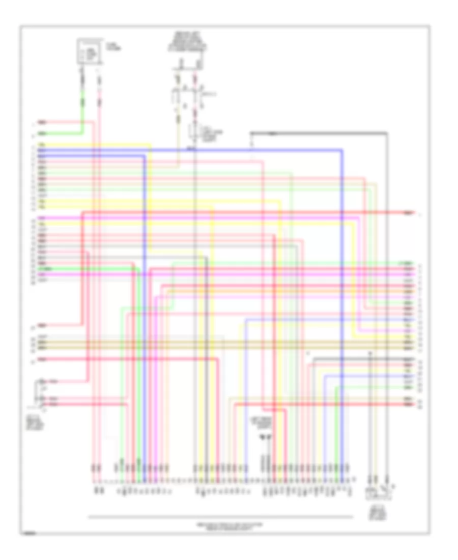
1.5L, Engine Controls Wiring Diagram (3 of 4) for Toyota Prius 2004
List of elements for 1.5L, Engine Controls Wiring Diagram (3 of 4) for Toyota Prius 2004:
- (lower left side of dash) data link connector 3
- (right side of dash) center connector 2
- 12v from converter
- A13
- Accel position sensor (upper left side of dash)
- Bean ic
- Bpa
- Ca1h
- Ca1l
- Canh
- Canl
- Chs w/p fuse 10a
- Combination meter
- Computer data lines system
- D11
- Dome fuse 15a
- Driver side j/b (left side of engine compt)
- E21
- Engine room r/b (left side of engine compt)
- Ep1
- Ep2
- Etcs fuse 10a
- F11
- F15
- Gateway ecu (upper center of dash)
- Gauge fuse 10a
- Gtx+
- Gtx-
- H14 canl
- H16
- H16 go
- Heated oxygen sensor (bank 1 sensor 2) (near rear of engine)
- Hot at all times
- Hot w/ ign on
- Hybrid vehicle control ecu (right side of dash)
- Ign fuse 7.5a
- J/c 6 (right end of dash)
- L16
- Malfunction ind
- Master
- Mpd1
- Mpd2
- Multi-display
- Nca
- Neo
- Pnk
- Red
- System data lines computer
- Tx1+
- Vcp1
- Vcp2
- Vcpa
- Vfd
- Vpa
- Vpa1
- Vpa2
1.5L, Engine Controls Wiring Diagram (4 of 4) for Toyota Prius 2004
List of elements for 1.5L, Engine Controls Wiring Diagram (4 of 4) for Toyota Prius 2004:
- (behind center of dash)
- (dash harn, left side of dash)
- (dash harn, right end of dash)
- (left side of dash) center connector 1
- (left side of dash) power source control ecu
- (left side of dash) skid control ecu
- (rear of engine)
- +bm
- Am2
- Ambient temperature sensor (left front of vehicle)
- Batt
- C10
- Canh
- Canl
- Ccv
- Computer data lines system
- Conn e6
- Conn e7
- Coolant heat storage tank outlet temperature sensor (left front of eng compt)
- Cooling fans system
- E03
- E12
- Engine control module (right end of dash)
- Fan
- H14
- H15
- Ht1b
- I10
- I11
- I12
- I16
- Ig2d
- Igsw
- J/c 1 (left side of eng compt)
- J/c 32 (right rear of vehicle)
- Mpx1
- Mpx2
- Mrel
- Nca
- Neo
- Ox1b
- Pnk
- Ptnk
- Red
- Sp1
- Tam
- Tbp
- Thw2
- Vapor pressure sensor (under left rear rear of vehicle)
- Vcc
- Vsv (canister closed valve) (under left rear of vehicle)
- Vsv (purge flow switching valve) (under center rear of vehicle)
- Water valve (left front of eng compt)
- Wbad
- Wpl
- Wsad
- Wsl1
- Wsl2
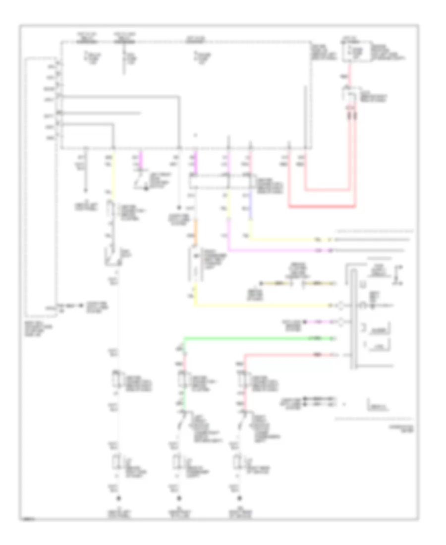
EXTERIOR LIGHTS
Backup Lamps Wiring Diagram for Toyota Prius 2004
List of elements for Backup Lamps Wiring Diagram for Toyota Prius 2004:
- A13
- A19
- Back-up lamp
- Bk/up lp relay
- Bn (rear of vehicle)
- C15
- Can h
- Can l
- Center connector 1 (behind cluster)
- Center connector 1 (behind combination meter)
- Center connector 2 (right i/p brace)
- Combination meter
- Computer data lines system
- D11
- Dome fuse 15a
- Driver side j/b (behind left end of dash)
- E14
- E2x1
- E2x2
- Engine room j/b (left side of engine compt)
- Engine room r/b (left side of engine compt)
- Gauge fuse 10a
- H15
- H16
- Hot at all times
- Hot in run or start
- Hybrid vehicle control ecu (behind right side of dash)
- I15
- Ih (above left kick panel)
- Ii (behind center of dash)
- J/c 10 (behind right side of dash)
- J/c 31 (rear of passenger compt)
- J/c 6 (behind right end of dash)
- L16
- Left rear combination light
- Pnk
- Red
- Right rear combination light
- Shift lever position sensor (behind center of dash)
- Vcx1
- Vcx2
- Vcx3
- Vcx4
- Vsx1
- Vsx2
- Vsx3
- Vsx4
Exterior Lamps Wiring Diagram (1 of 2) for Toyota Prius 2004
List of elements for Exterior Lamps Wiring Diagram (1 of 2) for Toyota Prius 2004:
- (behind center of dash)
- A11
- A12
- A14
- A15
- A31
- A32
- A33
- Body ecu
- C11
- C14
- C21
- Center connector 1 (behind combination meter)
- Combination meter
- Combination switch
- D10
- D27
- D28
- D29
- Dc/dc fuse 100a
- Driver side j/b (behind left side of dash)
- E10
- E12
- E17
- E28
- Ea (right side of engine compt)
- Ee (left rear of engine compt)
- Ef (left rear of engine compt)
- Ehw
- Engine room j/b (left side of engine compt)
- Engine room r/b (left side of engine compt)
- Flasher relay
- G14
- G15
- Gauge fuse 10a
- Gnd
- H15
- Haz fuse 10a
- Hazard switch
- Head
- Hot at all times
- Hot in run or start
- Ih (above left kick panel)
- Interior lights system
- J/c 11 (behind left end of dash)
- J/c 2 (left side of engine compt)
- J/c 4 (left side of engine compt)
- L11
- L12
- L13
- L16
- L17
- Left front side marker light
- Left front turn signal light
- Left turn ind
- Light control switch
- Off
- Panel fuse 7.5a
- Pnk
- Red
- Right front side marker light
- Right front turn signal light
- Right turn ind
- T-lp relay
- Tail
- Tail fuse 10a
- Trly
- Turn signal switch
Exterior Lamps Wiring Diagram (2 of 2) for Toyota Prius 2004
List of elements for Exterior Lamps Wiring Diagram (2 of 2) for Toyota Prius 2004:
- A18
- Back up
- Back-up lamps circuit
- Bn (rear of vehicle)
- Bo (right rear of vehicle)
- Driver side j/b (behind left side of dash)
- High mounted stop light
- Hot at all times
- J/c 31 (rear of passenger compt)
- J/c 34 (rear of vehicle)
- J/c 9 (behind left end of dash)
- Left license plate light
- Left rear combination light
- Noise filter (rear of vehicle)
- Red
- Right license plate light
- Right rear combination light
- Stop
- Stop fuse 7.5a
- Stop light switch (above brake pedal)
- Tail
- Turn
GROUND DISTRIBUTION
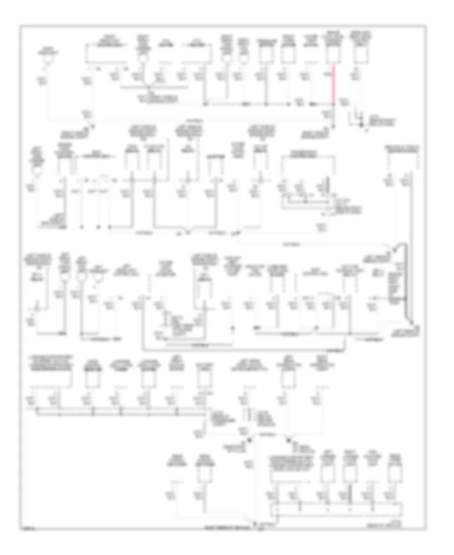
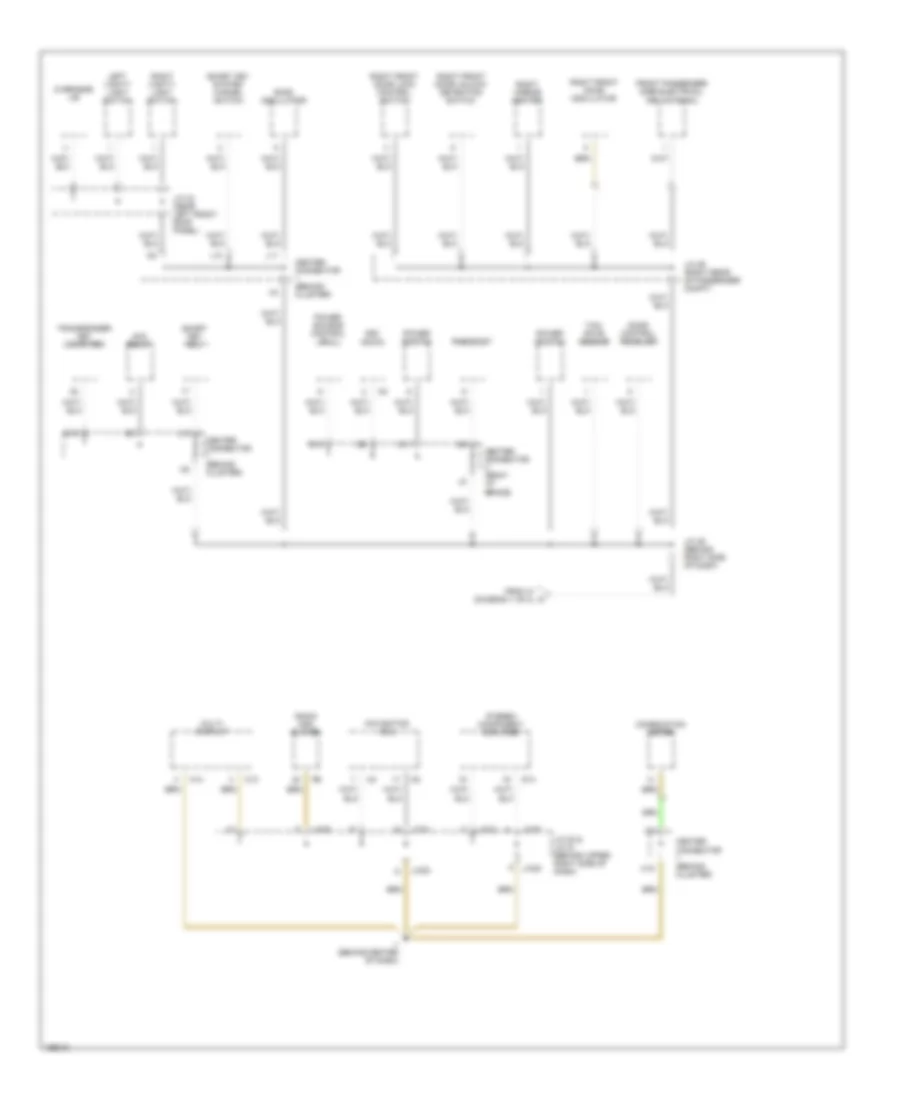
Ground Distribution Wiring Diagram (1 of 3) for Toyota Prius 2004
List of elements for Ground Distribution Wiring Diagram (1 of 3) for Toyota Prius 2004:
- (left side of eng compt) e3
- (left side of engine compt) engine room j/b
- (left side of engine compt) engine room r/b
- (right rear of vehicle)
- A/c w/p relay
- Abs & ba & trac & vsc actuator
- B j12
- B11
- Battery ecu
- Bl (near right "b" pillar)
- Bn (at rear of vehicle)
- Brake fluid level warning switch
- Coolant heat storage water pump
- Daytime running light relay
- Door control receiver
- Drl 4 relay
- E1 (right side of engine compt)
- Ea (right side of engine compt)
- Eb (right side of engine compt)
- Ee (left rear of engine compt)
- Ef (left rear of engine compt)
- Efi m relay
- Engine hood courtesy switch
- Engine room r/b 2 (right side of reserve tank)
- Fan2 relay
- Front wiper motor
- Headlight beam level control ecu
- High mounted stop light
- Ig2 relay
- Igct relay
- Inverter
- J/c 12 & j/c 13 (behind right side of dash)
- J/c 28 (below center console)
- J/c 30 (rear of passenger compt)
- J/c 34 (rear of vehicle)
- J/c 5 (behind right end of dash)
- J12
- J13
- Left front buckle switch
- Left front fog light
- Left front side marker light
- Left front turn signal light
- Left headlight
- Left headlight control ecu
- Left license plate light
- Left rear combination light
- Left rear door unlock detection switch
- Luggage compartment courtesy switch/ luggage compartment door opener motor
- Luggage compartment door opener switch luggage compartment door lock switch
- Luggage oscillator (inner)
- Luggage oscillator (outer)
- P con mtr relay
- Pnk
- Pressure switch
- Ptc heater
- Radiator fan motor
- Rear window defogger
- Rear wiper motor
- Right front fog light
- Right front side marker light
- Right front turn signal light
- Right headlight
- Right headlight control ecu
- Right license plate light
- Right rear combination light
- S10
- S27 & s28 (left rear of engine compt)
- Skid control ecu
- Transmission control ecu
- Water pump motor (a/c)
- Water pump motor (inverter)
- Water temp switch
- Wireless door lock buzzer
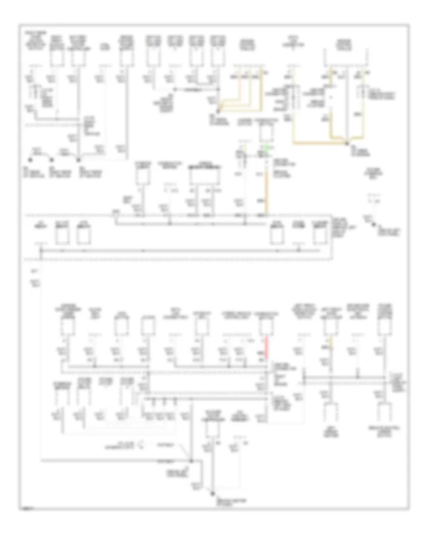
Ground Distribution Wiring Diagram (2 of 3) for Toyota Prius 2004
List of elements for Ground Distribution Wiring Diagram (2 of 3) for Toyota Prius 2004:
- A/c control assembly
- A11
- A18
- Airbag sensor assembly
- Battery blower motor controller
- Blower motor controller
- Bm (at rear of vehicle)
- Body ecu
- Bp (right rear of vehicle)
- Bq (right rear of vehicle)
- C11
- C13
- C16
- Center connector (behind cluster)
- Center connector (right i/p brace)
- Clock
- Combination switch
- Data link connector
- Data link connector 3
- Driver side electrical key antenna
- Driver side j/b (behind left end of dash)
- E12
- E14
- E17
- E2 (front center of engine compt)
- E28
- E30
- Ec (at rear of engine)
- Ed (at rear of engine)
- Engine control module
- F12
- F13
- Flasher relay
- Fuel pump
- G14
- G15
- Garage door opener/ inner mirror
- Gateway ecu
- Glove box light
- Gnd
- H14
- Hazard switch
- Htr relay
- Hybrid vehicle control ecu
- I11
- Ig (above left kick panel)
- Ig1 relay
- Ignition coil and igniter
- Ih (above left kick panel)
- Ij (behind center of dash)
- Interior light
- Inv w/p relay
- J/c 12 (behind right side of dash)
- J/c 24 (behind left end of dash)
- J/c 27 (left side of pass compt)
- J/c 29 (in right rear door)
- J/c 32 (right rear of vehicle)
- Left front door oscillator
- Left front door unlock detection switch
- Left mirror heater
- M10
- Main switch
- N10
- Noise filter
- Power outlet
- Power outlet relay
- Power steering ecu
- Power window master switch
- Pwr relay
- Red
- Remote control mirror switch
- Right front buckle switch
- Right rear door unlock detection switch
- Steering sensor
- To j/c 25 (diagram 3 of 3)
Ground Distribution Wiring Diagram (3 of 3) for Toyota Prius 2004
List of elements for Ground Distribution Wiring Diagram (3 of 3) for Toyota Prius 2004:
- Acc relay
- Center connector (behind cluster)
- Center connector (right i/p brace)
- Combination meter
- D13
- Door control receiver
- From ih (diagram 1 of 2) a
- Front passenger side electrical key antenna
- G10
- G11
- H15
- Ii (behind center of dash)
- J/c 20 & j/c 21 (behind upper right side of dash)
- J/c 25 (behind right side of dash)
- J/c 26 (right rear of passenger compt)
- J/c 33 (near left front roof panel)
- J/c20
- J/c21
- Key slot
- L10
- L11
- L12
- Left vanity light switch
- M13
- M14
- Multi- display
- Navigation ecu
- Overhead j/b
- Power source control ecu
- Power switch
- Radio and player
- Rheostat
- Right front door lock control switch
- Right front door oscillator
- Right front door unlock detection switch
- Right mirror heater
- Right vanity light switch
- Room oscillator
- S14
- Smart key ecu
- Smart key system cancel switch
- Stereo component amplifier
- Transponder key computer
- Yaw rate sensor
HEADLIGHTS
Headlamp Beam Adjustment Wiring Diagram for Toyota Prius 2004
List of elements for Headlamp Beam Adjustment Wiring Diagram for Toyota Prius 2004:
- (behind center of dash) ii
- (behind cluster) center connector 1
- (behind left end of dash) driver side j/b
- (vfd)
- A13
- A19
- Anti-lock brakes system
- Auto
- Body ecu (on right side of driver side j/b)
- Buzzer
- Center connector 1 (behind cluster)
- Center connector 2 (behind right side of dash)
- Combination meter
- Combination switch
- Computer data lines system
- D11
- D12
- Dome fuse 15a
- Driver side j/b (behind left end of dash)
- E17
- E28
- Engine room j/b (left side of engine compt)
- Engine room r/b (left side of engine compt)
- F14
- G14
- Gauge fuse 10a
- Gnd
- H-lp relay
- H15
- H16
- Hdlp
- Head
- Headlamps & foglamps circuit
- Headlight beam level control ecu (above right kick panel)
- Height control sensor (rear of vehicle)
- Hot at all times
- Hot in on and start
- Hrly
- Ih (above left kick panel)
- Ik (right end of dash)
- J/c 10 (behind right side of dash)
- J/c 5
- J/c 6 (behind right end of dash)
- J/c 7, 8 (behind left end of dash)
- L16
- Left headlight beam level control actuator (behind left headlight)
- Lh 1
- Lh 3
- Lh 4
- Lh+
- Lh-
- Lht
- Light control switch
- Main head fuse 40a
- Master
- N16
- Off
- Pnk
- Prst
- Red
- Rh 1
- Rh 3
- Rh 4
- Rh+
- Rh-
- Rht
- Right headlight beam level control actuator (behind right headlight)
- Sbr
- Sgr
- Shb
- Shg
- Shr
- Shrl
- Spdr
- Tail
- Wng
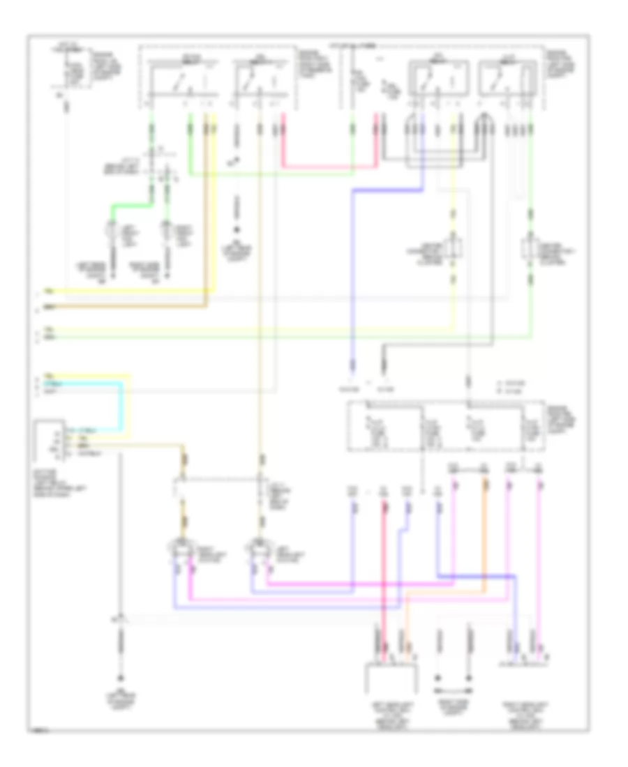
Headlamps & Fog Lamps Wiring Diagram, with DRL (1 of 2) for Toyota Prius 2004
List of elements for Headlamps & Fog Lamps Wiring Diagram, with DRL (1 of 2) for Toyota Prius 2004:
- (behind center of dash) ii
- (behind cluster) center connector 1
- (behind left end of dash)
- (vfd)
- A13
- A30
- A33
- Acc
- Acc fuse 7.5a
- Auto
- Automatic light control sensor upper left side of dash)
- B10
- B14
- B15
- Beam ind
- Bean ind
- Body ecu (on right side of driver side j/b)
- Center connector 1 (behind cluster)
- Center connector 2 (behind right side of dash)
- Cltb
- Clte
- Clts
- Combination meter
- Combination switch
- Computer data lines system
- D11
- D21
- Dbd2
- Dcty
- Dimmer switch
- Dome fuse 15a
- Driver side j/b (behind left end of dash)
- Drl diode
- Drl/dim
- E17
- E28
- Ecu b fuse 15a
- Ecu ig fuse 7.5a
- Ecub
- Engine room r/b (left side of engine compt)
- Exterior lights system
- F10
- F12
- F14
- Ffog
- Flash
- Foglight switch
- G14
- Gauge fuse 10a
- Gnd
- H15
- H16
- Head
- High
- Hon
- Hot at all times
- Hot in on and start
- Hot w/ acc relay energized
- Hrly
- Ih (above left kick panel)
- J/c 11 (behind left end of dash)
- J/c 19 (behind left end of dash)
- J/c 6 (behind right end of dash)
- J/c 9 (behind left end of dash)
- K10
- L16
- Left front door courtesy switch
- Lib1
- Light control switch
- Low
- Mpx1
- Mpx2
- Off
- Pnk
- Pwm1
- Red
- Sig
- Tail
- Tail fuse 10a
- Trly
Headlamps & Fog Lamps Wiring Diagram, with DRL (2 of 2) for Toyota Prius 2004
List of elements for Headlamps & Fog Lamps Wiring Diagram, with DRL (2 of 2) for Toyota Prius 2004:
- (left rear of engine compt) ee
- (right side of engine compt)
- (right side of engine compt) ea
- A w/o hid
- B w/ hid
- Center connector 1 (behind cluster)
- Daytime running light relay (behind upper left side of dash)
- Dim relay
- Drl
- Drl fuse 7.5a
- Drl relay 4
- Ee (left rear of engine compt)
- Engine room j/b (left side of engine compt)
- Engine room r/b (left side of engine compt)
- Engine room r/b 2 (right side of reserve tank)
- Fr fog fuse 15a
- Fr fog relay
- H-lp hi lh fuse 10a
- H-lp hi rh fuse 10a
- H-lp lo lh fuse 10a 15a
- H-lp lo rh fuse 10a 15a
- H-lp relay
- Hot at all times
- J/c 11 (behind left end of dash)
- J/c 7, 8 (behind left end of dash)
- Left front fog light
- Left headlight (w/o hid)
- Left headlight control ecu (w/ hid) (behind left headlight)
- Main head fuse 40a
- Pnk
- Right front fog light
- Right headlight (w/o hid)
- Right headlight control ecu (w/ hid) (behind left headlight)
- W/ hid
- W/o hid
Headlamps & Fog Lamps Wiring Diagram, without DRL (1 of 2) for Toyota Prius 2004
List of elements for Headlamps & Fog Lamps Wiring Diagram, without DRL (1 of 2) for Toyota Prius 2004:
- (behind center of dash) ii
- (behind cluster) center connector 1
- (vfd)
- A13
- A30
- A33
- Acc
- Acc fuse 7.5a
- Auto
- Automatic light control sensor upper left side of dash)
- B10
- B14
- B15
- Beam ind
- Bean ind
- Body ecu (on right side of driver side j/b)
- Center connector 1 (behind cluster)
- Center connector 2 (behind right side of dash)
- Cltb
- Clte
- Clts
- Combination meter
- Combination switch
- Computer data lines system
- D11
- D21
- Dbd2
- Dcty
- Dimmer switch
- Dome fuse 15a
- Driver side j/b (behind left end of dash)
- Drl/dim
- E17
- E28
- Ecu ig fuse 7.5a
- Ecub
- Engine room r/b (left side of engine compt)
- Exterior lights system
- F10
- F12
- F14
- Ffog
- Flash
- Foglight switch
- G14
- Gauge fuse 10a
- Gnd
- H15
- H16
- Head
- High
- Hot at all times
- Hot in on and start
- Hot w/ acc relay energized
- Hrly
- Ih (above left kick panel)
- J/c 11 (behind left end of dash)
- J/c 6 (behind right end of dash)
- L16
- Left front door courtesy switch
- Lib1
- Light control switch
- Low
- Mpx1
- Mpx2
- Off
- Pnk
- Red
- Sig
- Tail
- Tail fuse 10a
- Trly
Headlamps & Fog Lamps Wiring Diagram, without DRL (2 of 2) for Toyota Prius 2004
List of elements for Headlamps & Fog Lamps Wiring Diagram, without DRL (2 of 2) for Toyota Prius 2004:
- (left rear of engine compt) ee
- (right side of engine compt)
- (right side of engine compt) ea
- A w/o hid
- B w/ hid
- Center connector 1 (behind cluster)
- Dim relay
- Ee (left rear of engine compt)
- Engine room j/b (left side of engine compt)
- Engine room r/b (left side of engine compt)
- Engine room r/b 2 (right side of reserve tank)
- Fr fog fuse 15a
- Fr fog relay
- H-lp hi lh fuse 10a
- H-lp hi rh fuse 10a
- H-lp lo lh fuse 10a 15a
- H-lp lo rh fuse 10a 15a
- H-lp relay
- Hot at all times
- J/c 7, 8 (behind left end of dash)
- Left front fog light
- Left headlight (w/o hid)
- Left headlight control ecu (w/ hid) (behind left headlight)
- Main head fuse 40a
- Pnk
- Right front fog light
- Right headlight (w/o hid)
- Right headlight control ecu (w/ hid) (behind left headlight)
- W/ hid
- W/o hid
HORN
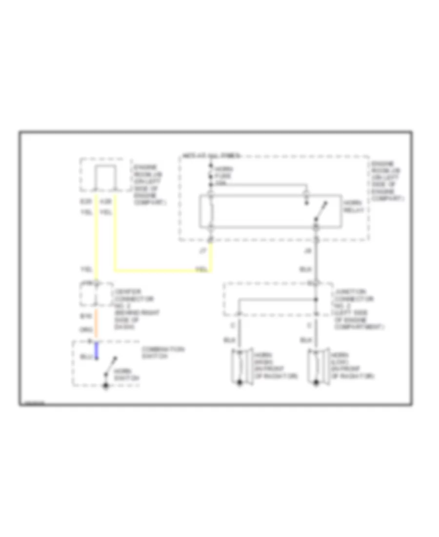
Horn Wiring Diagram for Toyota Prius 2004
List of elements for Horn Wiring Diagram for Toyota Prius 2004:
- A28
- B16
- Center connector no. 2 (behind right side of dash)
- Combination switch
- E25
- Engine room j/b (on left side of engine compart)
- Horn (high) (in front of radiator)
- Horn (low) (in front of radiator)
- Horn fuse 10a
- Horn relay
- Horn switch
- Hot at all times
- I16
- Junction connector no. 2 (left side of engine compartment)
INSTRUMENT CLUSTER
Instrument Cluster Wiring Diagram for Toyota Prius 2004
List of elements for Instrument Cluster Wiring Diagram for Toyota Prius 2004:
- (behind center of dash) ii
- (vfd)
- A13
- A14
- A15
- A16
- Abs ind
- Anti-theft system anti-lock brakes system
- Auto a/c ind
- Beam ind
- Bean ic
- Bl (near right "b" pillar)
- Bq (right rear of vehicle)
- Brake control ind
- Brake ind
- Buzzer
- C10
- Center connector 1 (behind cluster)
- Center connector 2 (behind right side of dash)
- Combination meter
- Computer data lines system
- Cruise ind
- D10
- D11
- D12
- D14
- Dome fuse 15a
- Door ind
- Driver side j/b (behind left
- Driver side j/b (behind left end of dash)
- E11
- E12
- End of dash)
- Engine control system
- Engine controls system
- Engine room j/b (left side of engine compt)
- Engine room r/b (left side of engine compt)
- Exterior lights system
- F15
- Front def ind
- Front passenger seat belt warning light
- Fuel sender
- Gauge fuse 10a
- H15
- H16
- Head ind
- Headlights system
- Headlights systems
- Hot at all times
- Hot in on and start
- I12
- I13
- Ice road condition ind
- Ign fuse 7.5a
- Inlet air ind
- Interior lights system
- J/c 30 (rear of passenger compt)
- J/c 32 (right rear of vehicle)
- J/c 6 (behind right end of dash)
- K14
- K15
- L16
- Left front buckle switch
- Left turn ind
- Maint reqd ind
- Malfunction ind lamp
- Master
- N15
- Navigation system
- Odo
- Odo/trip switch
- Pnk
- Power distribution
- Rear def ind
- Red
- Right front buckle switch
- Right turn ind
- Seat belt ind
- Security ind
- Slip ind
- Smart entry ind
- Sound systems
- Srs ind
- Temp sensor
- Vsc ind
INTERIOR LIGHTS
Courtesy Lamps Wiring Diagram (1 of 2) for Toyota Prius 2004
List of elements for Courtesy Lamps Wiring Diagram (1 of 2) for Toyota Prius 2004:
- A13
- A15
- A30
- A33
- Acc
- Acc fuse 7.5a
- Body ecu
- C21
- Center connector 1 (behind combination meter)
- Center connector 2 (right i/p brace)
- Center of dash)
- Combination meter
- Combination switch
- Computer data lines system
- D10
- D11
- D29
- Dc/dc fuse 100a
- Dome fuse 15a
- Door
- Driver side j/b (behind left side of dash)
- E10
- E17
- E27
- E28
- Ecu-ig fuse 7.5a
- Ecub
- Engine room j/b (left side of engine compt)
- Engine room r/b (left side of engine compt)
- Exterior lights system
- G14
- Glove box light
- Gnd
- H15
- H16
- Head
- Hot at all times
- Hot in run or start
- Hot w/ acc relay energized
- Ih (above left kick panel)
- Ii (behind
- Ill
- Instrument illumination circuit
- Interior light
- J/c 24 (left end of dash)
- J/c 6 (behind right end of dash)
- K16
- Key slot
- Light control switch
- Mpx1
- Mpx2
- Off
- Panel fuse 7.5a
- Pnk
- Red
- Sig
- T-lp relay
- Tail
- Tail fuse 10a
- Trly
Courtesy Lamps Wiring Diagram (2 of 2) for Toyota Prius 2004
List of elements for Courtesy Lamps Wiring Diagram (2 of 2) for Toyota Prius 2004:
- A10
- A19
- Bcty
- Bl (near right "a" pillar)
- Bl (near right "b" pillar)
- Body ecu
- Bq (right rear of vehicle)
- C10
- C25
- Center connector 1 (behind combination meter)
- Center connector 2 (right i/p brace)
- Cylb
- Cyld
- Cylp
- D20
- D21
- D24
- Data link connector 3 (behind lower left side of dash)
- Dcty
- Door
- Driver side j/b (behind left side of dash)
- F15
- H11
- Ih (above left kick panel)
- J/c 23 (in center console)
- J/c 26 (right rear of passenger compt)
- J/c 27 (left side of passenger compt)
- J/c 28 (below center console)
- J/c 29 (in right rear door)
- J/c 30 (rear of passenger compt)
- J/c 31 (rear of passenger compt)
- J/c 33 (near left front roof panel)
- K16
- Left front door courtesy light
- Left front door courtesy switch
- Left front door unlock detection switch
- Left rear door courtesy switch
- Left rear door unlock detection switch
- Left vanity light
- Left vanity light switch
- Lswd
- Lswp
- Lswr
- Luggage compartment courtesy switch
- Luggage compartment light
- Obd2
- Overhead j/b (front of roof panel)
- Pcty
- Rcty
- Red
- Right front door courtesy light
- Right front door courtesy switch
- Right front door unlock detection switch
- Right rear door courtesy switch
- Right rear door unlock detection switch
- Right vanity light
- Right vanity light switch
Instrument Illumination Wiring Diagram for Toyota Prius 2004
List of elements for Instrument Illumination Wiring Diagram for Toyota Prius 2004:
- A10
- A12
- A13
- A15
- A33
- B12
- Body ecu
- Built-in amp
- C21
- Center connector 1 (behind combination meter)
- Center connector 2 (right i/p brace)
- Combination meter
- Combination switch
- Computer data lines system
- Courtesy lights circuit
- D10
- D11
- D15
- D29
- Dc/dc fuse 100a
- Dome fuse 15a
- Driver side j/b (behind left side of dash)
- E10
- E14
- E17
- E28
- Engine room j/b (left side of engine compt)
- Engine room r/b (left side of engine compt)
- Exterior lights system
- F14
- G14
- G16
- Gauge fuse 10a
- Gnd
- H15
- H16
- Hazard switch
- Head
- Hot at all times
- Hot in run or start
- Ih (above left kick panel)
- Ii (behind center of dash)
- Ill+
- Ill-
- J/c 19 (behind left end of dash)
- J/c 25 (behind right side of dash)
- J/c 6 (behind right end of dash)
- K13
- L16
- Light control switch
- M16
- Main switch
- Multi- display
- Off
- Panel fuse 7.5a
- Pnk
- Radio & player
- Red
- Rheostat
- Separate amp
- Shift lever position sensor
- T-lp relay
- Tail
- Tail fuse 10a
- Trly
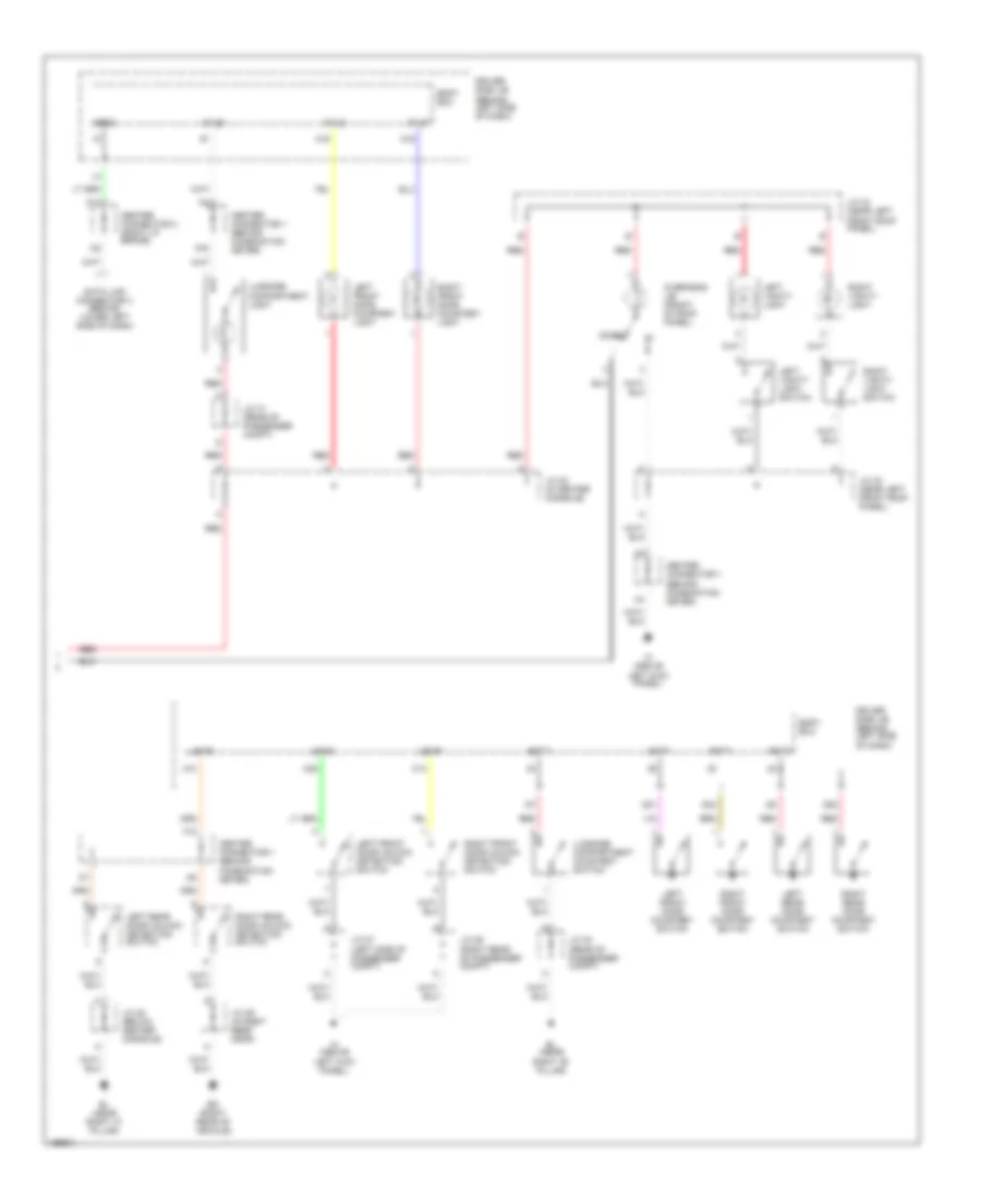
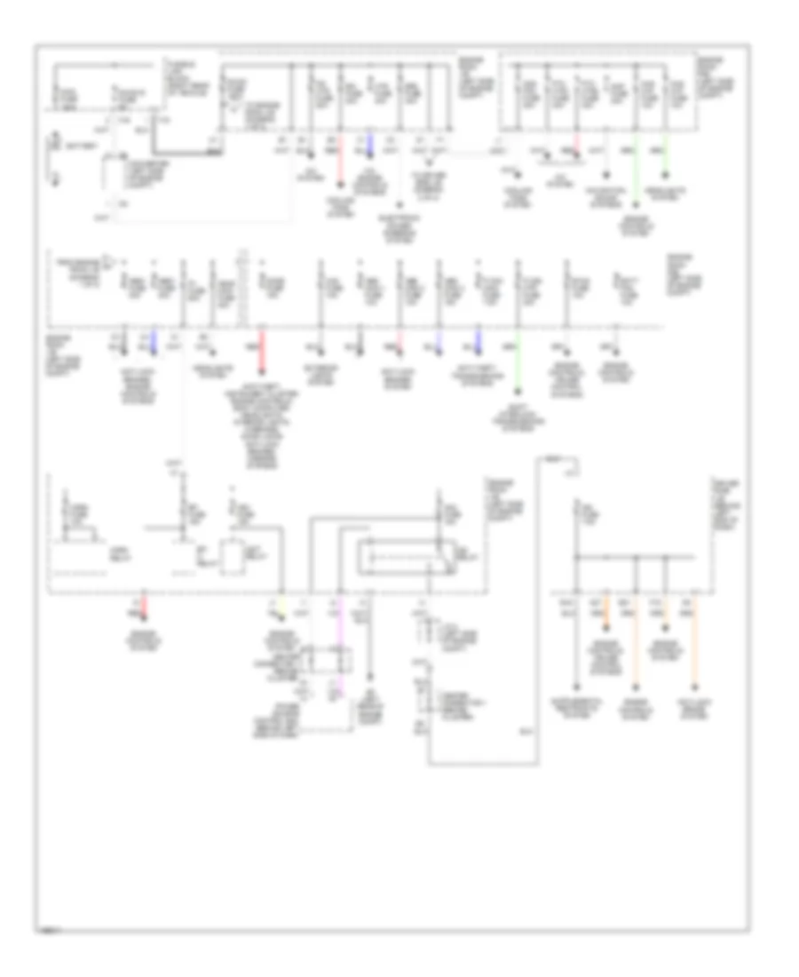
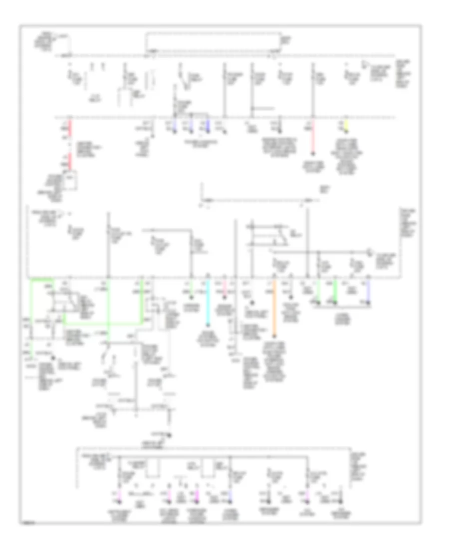
POWER DISTRIBUTION
Power Distribution Wiring Diagram (1 of 2) for Toyota Prius 2004
List of elements for Power Distribution Wiring Diagram (1 of 2) for Toyota Prius 2004:
- A/c system
- A/c, engine controls systems
- A27
- Abs main 1 fuse 10a
- Abs main 2 fuse 10a
- Abs main 3 fuse 15a
- Abs1 fuse 30a
- Am2 fuse 15a
- Amp fuse 30a
- Anti-lock brake system
- Anti-lock brakes system
- Anti-lock brakes, engine controls systems
- Anti-theft, instrument cluster, engine controls, body computer, headlights, interior lights, warnings, door locks anti-lock brakes, mirrors systems
- Anti-theft, transmissions systems
- Batt fan fuse 10a
- Battery
- Cds fan fuse 30a
- Center connector 1 (behind cluster)
- Chs w/p fuse 10a
- Converter (left side of engine compt)
- Cooling fans system
- Dc/dc fuse 100a
- Dc/dc-s fuse 5a
- Dome fuse 15a
- Driver side j/b (behind left end of dash)
- E16
- E21
- Ef (left rear of engine compt)
- Efi fuse 15a
- Efi m relay
- Electronic power steering system
- Engine controls system
- Engine controls, cruise control systems
- Engine room j/b (left side of engine compt)
- Engine room r/b (left side of engine compt)
- Eps fuse 40a
- Etcs fuse 10a
- Exterior lights system
- F15
- F16
- From engine a room j/b (diagram 1 of 2)
- Fusible link block (right rear of vehicle)
- Haz fuse 10a
- Head main fuse 40a
- Headlights system
- Hev fuse 15a
- Horn fuse 10a
- Horn relay
- Htr fuse 40a
- Ig2 relay
- Igct relay
- Ign fuse 7.5a
- J/c 2 (left side of engine compt)
- Main fuse 120a
- Navigation, sound systems
- P con main fuse 7.5a
- P con mtr fuse 30a
- P/i fuse 60a
- Power source control ecu (behind left side of dash)
- Ps htr fuse 50a
- Ptc htr1 fuse 30a
- Ptc htr2 fuse 30a
- Rdi fuse 30a
- Red
- Shift interlock, transmissions systems
- To driver side j/b (diagram 2 of 2)
- To engine room j/b (diagram 1 of 2)
Power Distribution Wiring Diagram (2 of 2) for Toyota Prius 2004
List of elements for Power Distribution Wiring Diagram (2 of 2) for Toyota Prius 2004:
- (not used)
- A/c (htr) fuse 10a
- A/c defogger system
- A/c system
- A/c, head/ exterior lights system
- A10
- A18
- A19
- A24
- A29
- A36
- Acc
- Acc fuse 7.5a
- Acc relay (behind left side of dash)
- Acc-b fuse 25a
- Accd
- Altb
- Am1
- Am1 fuse 7.5a
- Body ecu
- Center connector 1 (behind cluster)
- Computer data lines electronic power steering, anti-lock brake, mirrors navigation systems
- Computer data lines system
- Computer data lines, headlamps body computer navigation sound systems, anti-theft system
- Cooling fans anti-lock brake system
- D17
- D25
- Def fuse 40a
- Def relay
- Defogger system
- Door fuse 25a
- Driver side j/b (behind left end of dash)
- E11
- E17
- Ecu-b fuse 15a
- Ecu-ig fuse 7.5a
- Engine controls system
- Engine controls, cruise control, exterior lights, anti-lock brake systems
- Flasher relay
- Fr door fuse 20a
- From driver side j/b (diagram 2 of 2)
- From engine b room j/b (diagram 1 of 2)
- G14
- Gauge fuse 10a
- H10
- H11
- Htr relay
- Ig1 relay
- Ig1d
- Ih (above left kick panel)
- Instrument cluster system
- J/c 20 & j/c 21 (upper right side of dash)
- J/c 24 (behind left end of dash)
- K10
- Kof
- L10
- L15 (not used)
- M/htr fuse 15a
- Mirrors system
- N10
- Obd fuse 7.5a
- Pnk
- Power fuse 30a
- Power outlet
- Power outlet relay (left end of dash)
- Power source control ecu (behind left side of dash)
- Power windows system
- Pwr outlet fr fuse 15a
- Pwr outlet fuse 15a
- Pwr relay
- Red
- Rr wip fuse 15a
- Sig
- Sound systems, navigation system
- Stop fuse 7.5a
- T-lp relay
- To driver side j/b (diagram 2 of 2)
- Warnings, power windows system
- Wip fuse 30a
- Wiper/ washer system
- Wsh fuse 20a
POWER DOOR LOCKS
Door Lock & Keyless Entry Wiring Diagram, with Smart Key System (1 of 4) for Toyota Prius 2004
List of elements for Door Lock & Keyless Entry Wiring Diagram, with Smart Key System (1 of 4) for Toyota Prius 2004:
- +b1
- Ant1
- Ant2
- Bean ic
- Bo (right rear op vehicle)
- Center connector 1 (behind left side of dash)
- Center connector 2 (behind right side of dash)
- Clg
- Clg1
- Clg2
- Clg7
- Clg8
- Cnsl
- Combination meter
- Computer data lines system
- Data
- Door control receiver (right side of passenger compt) +b
- Driver's side electrical key antenna (in driver's door)
- Engine room j/b (left side of engine compt)
- Front passenger's side electrical key antenna (in right front door)
- Gauge fuse 10a
- Gnd
- H15
- Hot w/ ig1 relay engergized
- I16
- Ii (behind center of dash)
- Inner luggage oscillator (at luggage compt)
- Interior lights system
- J/c 23 (in center console)
- J/c 31 (rear of passenger compt)
- J/c 34 (in rear of vehicle)
- Ksw
- L10
- L11
- L12
- L16
- Left front door oscillator (w/ sensor) (in left front door)
- Luggage compartment door electrical key antenna (in luggage compt)
- Luggage compartment door lock switch
- Mpx1
- Mpx2
- Outer luggage oscillator (at luggage compt)
- Pnk
- Prg
- Rco
- Rda
- Rda3
- Red
- Right front door oscillator (w/ sensor) (in right front door)
- Room oscillator (in center console)
- Rss1
- Sel
- Sel1
- Sel2
- Sen1
- Sen2
- Sens
- Sgt
- Skid control ecu (behind left side of dash)
- Smart entry
- Smart key ecu (behind left side of dash)
- Smart key system cancel switch
- Sp1
- Trg+
- Trg-
- Tsw1
- Tsw2
- Tsw6
Door Lock & Keyless Entry Wiring Diagram, with Smart Key System (2 of 4) for Toyota Prius 2004
List of elements for Door Lock & Keyless Entry Wiring Diagram, with Smart Key System (2 of 4) for Toyota Prius 2004:
- (above left kick panel) ih
- (behind right side of dash) center connector 2
- Acc
- Acc fuse 7.5a
- Altb
- Bact
- Bcty
- Bl (near right ``b" pillar)
- Body ecu
- Buz
- Center connector 2 (behind right side of dash)
- Computer data lines system
- Control switch
- D11
- Door fuse 25a
- Driver side j/b (behind left end of dash)
- E17
- E23
- E26
- Ecu-ig fuse 7.5a
- Ee (left rear of engine compt)
- Ef (left rear of engine compt)
- Engine hood courtesy switch (near hood latch)
- Flasher relay (exterior lights system)
- Gnd
- H13
- H14
- H15
- H16
- Haz
- Hcty
- Headlights system
- Hot at all times
- Hot w/ acc relay energized
- Hot w/ ecu-ig relay energized
- Hrly
- Ih (above left kick panel)
- Interior lights system
- J/c 24 (behind left end of dash)
- J/c 25 (behind right side of dash)
- J/c 26 (right rear of passenger compt)
- J/c 27 (left side of passenger compt)
- J/c 30 (rear of passenger compt)
- Ksw
- Left front buckle switch
- Lock
- Luggage compartment courtesy switch & luggage compartment door opener motor
- Mpx1
- Odb2
- Pnk
- Power windows system
- Prg
- Rda
- Red
- Red (or pnk)
- Right front door lock
- Sec
- Sig
- T-lp relay (exterior lights system)
- Theft deterrent horn (right side of engine compt) (w/ keyless entry)
- Trly
- Ul1
- Unlk
- Wireless door lock buzzer
Door Lock & Keyless Entry Wiring Diagram, with Smart Key System (3 of 4) for Toyota Prius 2004
List of elements for Door Lock & Keyless Entry Wiring Diagram, with Smart Key System (3 of 4) for Toyota Prius 2004:
- (behind left side of dash) center connector 1
- A13
- A28
- A30
- Acc
- Act+
- Act-
- Actd
- Bdsu
- Bl (near right "b" pillar)
- Bo (right rear of vehicle)
- Body ecu
- Bq (right rear of vehicle)
- Cyld
- D20
- D21
- D24
- Dbkl
- Dcty
- Dome fuse 15a
- Door fuse 25a
- Driver side j/b (behind left end of dash)
- E27
- Engine room j/b (left side of engine compt)
- F13
- F15
- H16
- H17
- Horns system (w/ keyless entry)
- Hot at all times
- Ih (above left kick panel)
- Interior lights system
- J/c 22 (above left kick panel)
- J/c 24 (behind left end of dash)
- J/c 25 (behind right side of dash)
- J/c 26 (right rear of passenger compt)
- J/c 27 (left side of passenger compt)
- J/c 28 (below center console)
- J/c 29 (in right rear door)
- J/c 32 (right rear of vehicle)
- J/c 34 (in rear of vehicle)
- J/c 6 (behind right end of dash)
- K15
- Left front door courtesy switch
- Left front door lock motor, & door unlock detection switch
- Left rear door courtesy switch
- Left rear door lock motor & door unlock detection switch
- Lswd
- Lswp
- Lswr
- Luggage compartment door opener switch
- Mpx2
- Pcty
- Pnk
- Rcty
- Red
- Red (or pnk)
- Right front door courtesy switch
- Right front door lock motor, & door unlock detection switch
- Right rear door courtesy switch
- Right rear door lock motor & door unlock detection switch
- Ul3
Door Lock & Keyless Entry Wiring Diagram, with Smart Key System (4 of 4) for Toyota Prius 2004
List of elements for Door Lock & Keyless Entry Wiring Diagram, with Smart Key System (4 of 4) for Toyota Prius 2004:
- (behind right side of dash) center connector 2
- Acc
- Acc fuse 7.5a
- Agnd
- Am1
- Am1 fuse 7.5a
- Am2
- Am2 fuse 15a
- Cdsw
- Center connector 1 (behind left side of dash)
- Code
- Cpub
- Cuws
- D11
- D12
- D13
- D14
- Driver side j/b (behind left end of dash)
- E10
- E11
- E13
- Engine room j/b (left side of engine compt)
- F11
- F15
- G10
- G11
- G13
- G14
- Gnd
- Gnd2
- H14
- Hev0
- Hev1
- Hot at all times
- Hot w/ acc relay energized
- Hot w/ ig2 relay energized
- Hybrid vehicle control ecu (behind right side of dash)
- I13
- I14
- Ign fuse 7.5a
- Igsw
- Ih (above left kick panel)
- Imp
- Inds
- Indw
- J/c 10 (behind right side of dash)
- J/c 14 (behind right side of dash)
- J/c 25 (behind right side of dash)
- J10
- J11
- J12
- J13
- J14
- J15
- J16
- Key slot
- Lin1
- Mpx1
- Mpx2
- P con main fuse 7.5a
- Pnk
- Power source control ecu (behind left side of dash)
- Power switch
- Ppos
- Rdy
- Red
- Sol1
- Sol2
- Ssw1
- Ssw2
- St2
- Stsw
- Swil
- Trans- ponder key coil
- Transmission control ecu (behind right side of dash)
- Transponder key amplifier
- Transponder key computer (behind upper left side of dash)
- Txct
- Vc5
Door Lock & Keyless Entry Wiring Diagram, without Smart Key System (1 of 2) for Toyota Prius 2004
List of elements for Door Lock & Keyless Entry Wiring Diagram, without Smart Key System (1 of 2) for Toyota Prius 2004:
- (above left kick panel) ih
- (behind left side of dash) center connector 1
- Acc
- Acc fuse 7.5a
- Altb
- Bact
- Bcty
- Bl (near right ``b" pillar)
- Body ecu
- Buz
- Center connector 2 (behind right side of dash)
- Computer data lines system
- Control switch
- Door control receiver (right side of passenger compt) (w/ keyless entry)
- Door fuse 25a
- Driver side j/b (behind left end of dash)
- E17
- E26
- Ecu-ig fuse 7.5a
- Ee (left rear of engine compt)
- Ef (left rear of engine compt)
- Engine hood courtesy switch (near hood latch)
- Flasher relay (exterior lights system)
- Gnd
- H13
- H14
- H16
- Haz
- Hcty
- Headlights system
- Hot at all times
- Hot w/ acc relay energized
- Hot w/ ecu-ig relay energized
- Hrly
- Ih (above left kick panel)
- Interior lights system
- J/c 25 (behind right side of dash)
- J/c 26 (right rear of passenger compt)
- J/c 30 (rear of passenger compt)
- Key slot
- Ksw
- Left front buckle switch
- Lock
- Luggage compartment courtesy switch & luggage compartment door opener motor
- Odb2
- Pnk
- Power windows system
- Prg
- Rda
- Red
- Right front door lock
- Sec
- Sig
- T-lp relay (exterior lights system)
- Theft deterrent horn (right side of engine compt) (w/ keyless entry)
- Trly
- Ul1
- Unlk
- Wireless door lock buzzer
Door Lock & Keyless Entry Wiring Diagram, without Smart Key System (2 of 2) for Toyota Prius 2004
List of elements for Door Lock & Keyless Entry Wiring Diagram, without Smart Key System (2 of 2) for Toyota Prius 2004:
- (behind left side of dash) center connector 1
- A13
- A28
- A30
- Acc
- Act+
- Act-
- Actd
- Bdsu
- Bl (near right "b" pillar)
- Bo (right rear of vehicle)
- Body ecu
- Bq (right rear of vehicle)
- Cyld
- D20
- D21
- D24
- Dbkl
- Dcty
- Dome fuse 15a
- Door fuse 25a
- Driver side j/b (behind left end of dash)
- Engine room j/b (left side of engine compt)
- F13
- F15
- H16
- H17
- Horns system (w/ keyless entry)
- Hot at all times
- Ih (above left kick panel)
- Interior lights system
- J/c 22 (above left kick panel)
- J/c 24 (behind left end of dash)
- J/c 25 (behind right side of dash)
- J/c 26 (right rear of passenger compt)
- J/c 27 (left side of passenger compt)
- J/c 28 (below center console)
- J/c 29 (in right rear door)
- J/c 32 (right rear of vehicle)
- J/c 34 (in rear of vehicle)
- J/c 6 (behind right end of dash)
- K15
- Left front door courtesy switch
- Left front door lock motor, & door unlock detection switch
- Left rear door courtesy switch
- Left rear door lock motor & door unlock detection switch
- Lswd
- Lswp
- Lswr
- Luggage compartment door opener switch
- Pcty
- Pnk
- Rcty
- Red
- Right front door courtesy switch
- Right front door lock motor, & door unlock detection switch
- Right rear door courtesy switch
- Right rear door lock motor & door unlock detection switch
- Ul3
- W/ keyless entry
POWER MIRRORS
Automatic Glare-Resistant EC Mirror Wiring Diagram for Toyota Prius 2004
List of elements for Automatic Glare-Resistant EC Mirror Wiring Diagram for Toyota Prius 2004:
- A13
- Center connector 2 (right i/p brace)
- Dome fuse 15a
- Drivers side j/b (behind left end of dash)
- Drivers side j/b (behind left side of dash)
- Ecu-ig fuse 7.5a
- Engine room r/b (left side of engine compartment)
- H16
- Hot at all times
- Hot with ig on
- Ih (above left kick panel)
- Inner mirror
- J/c 24 (behind left end of dash)
- J/c 6 (right i/p brace)
- Pnk
- Red
Power Mirrors Wiring Diagram for Toyota Prius 2004
List of elements for Power Mirrors Wiring Diagram for Toyota Prius 2004:
- Acc fuse 7.5a
- Center connector no.2 (behind right side of dash)
- Down
- H12
- Hot in acc or on
- Ih (above left kick panel)
- J/c 24 (behind left end of dash)
- J/c 26 (behind upper left center of dash)
- J/c 27 (behind upper left center of dash)
- J27
- Left
- Left remote control mirror
- Left/ right
- Operation switch
- Pnk
- Red
- Remote control mirror switch
- Right
- Right remote control mirror
- Select switch
- Up/ down
POWER WINDOWS
Power Windows Wiring Diagram for Toyota Prius 2004
List of elements for Power Windows Wiring Diagram for Toyota Prius 2004:
- (above left kick panel) ih
- A30
- Acc
- Acc fuse 7.5a
- Body ecu
- Brd
- Center connector 2 (behind right side of dash)
- D17
- D21
- Dc/dc fuse 100a
- Dcty
- Dome fuse 15a
- Down
- Driver side j/b (behind left end of dash)
- E left front power window motor
- E17
- Ecu-ig fuse 7.5a
- Engine room j/b (left side of engine compt)
- Fr door fuse 20a
- Gauge fuse 10a
- Gnd
- H10
- H11
- Hot at all times
- Hot w/ acc relay energized
- Hot w/ ecu-ig relay energized
- Hot w/ ig1 relay energized
- J/c 22 (above left kick panel)
- J/c 24 (behind left end of dash)
- J/c 27 (left side of passenger compt)
- J/c 6 (behind right end of dash)
- Kof
- Left front door courtesy switch
- Left rear power window control switch
- Left rear power window motor
- Pls
- Pls2
- Pnk
- Power fuse 30a
- Power window master switch
- Pwr relay
- Red
- Right front power window control switch
- Right front power window motor
- Right rear power window control switch
- Right rear power window motor
- Rld
- Rlu
- Rrd
- Rru
- Sig
- Ssrb
- Vcc
RADIO
Radio Wiring Diagram, with Built-in Amplifier for Toyota Prius 2004
List of elements for Radio Wiring Diagram, with Built-in Amplifier for Toyota Prius 2004:
- (right i/p brace)
- +b1
- A13
- A22
- Acc
- Acc fuse 7.5a
- Ant+
- Antenna amplifier (behind center of dash)
- Body ecu (on driver side j/b)
- Center connector (right i/p brace)
- Center connector 1 (behind cluster)
- Center connector 2
- Center connector 2 (right i/p brace)
- Combination meter
- Combination switch
- Computer data lines system
- D12
- Data link connector (behind lower left side of dash)
- Dome fuse 15a
- Driver side j/b (behind left end of dash)
- E10
- E12
- E13
- Ecu-b fuse 15a
- Ecu-ig fuse 7.5a
- Engine room r/b (left side of engine compt)
- Fl+
- Fl-
- Fr+
- Fr-
- Gnd
- Gnd1
- H13
- H14
- H15
- Hot at all times
- Hot w/ acc on
- Hot w/ ig on
- Hsd1
- Ii (behind center of dash)
- J/c 19 (behind left end of dash)
- J/c 20 (behind upper right side of dash)
- J/c 6 (behind right end of dash)
- J/c 9 (behind left end of dash)
- K10
- L13
- L15
- Left front door speaker
- Left front tweeter
- Left rear door speaker
- M13
- Mode
- Multi-display
- Parking brake switch (base of parking brake lever)
- Pkb
- Pnk
- Radio and player
- Red
- Right front door speaker
- Right front tweeter
- Right rear door speaker
- Rl+
- Rl-
- Rr+
- Rr-
- Seek +
- Seek -
- Spd
- Sw1
- Sw2
- Tx+
- Tx-
- Tx1+
- Tx1-
- Tx2+
- Tx2-
- Vol +
- Vol -
Radio Wiring Diagram, with Separate Amplifier (1 of 2) for Toyota Prius 2004
List of elements for Radio Wiring Diagram, with Separate Amplifier (1 of 2) for Toyota Prius 2004:
- (behind center of dash) ii
- (right i/p brace)
- +b1
- A22
- Acc
- Acc fuse 7.5a
- Aui+
- Aui-
- Auo+
- Auo-
- Bk/up lp relay
- Body ecu (on driver side j/b)
- Center connector 1 (behind cluster)
- Center connector 2
- Center connector 2 (right i/p brace)
- Combination meter
- Computer data lines system
- D12
- Data link connector (behind lower left side of dash)
- Driver side j/b (behind left end of dash)
- E shield
- E10
- E11
- E12
- E13
- Ecu-b fuse 15a
- Ecu-ig fuse 7.5a
- Engine room j/b (left side of engine compt)
- Gnd1
- H13
- H14
- H15
- Hot at all times
- Hot w/ acc on
- Hot w/ ig on
- Hsd1
- Ii (behind center of dash)
- Ivo+
- Ivo-
- J/c 10 (behind right side of dash)
- J/c 19 (behind left end of dash)
- J/c 20 & j/c 21 (behind upper right side of dash)
- J/c 20 (behind upper right side of dash)
- J/c 9 (behind left end of dash)
- J/c20
- J/c21
- K10
- L13
- L15
- M13
- M14
- Macc
- Mco+
- Mco-
- Mi+
- Mic+
- Mic-
- Min+
- Min-
- Multi-display
- Mut2
- N14
- Navigation ecu (below driver's seat)
- Overhead j/b (front of roof panel)
- Parking brake switch (base of parking brake lever)
- Pkb
- Pnk
- Red
- Red h8
- Rev
- Sgnd
- Shield
- Sld
- Snse
- Spd
- Sync
- Tx+
- Tx-
- Tx1+
- Tx1-
- Tx2+
- Tx2-
- Vo1+
- Vo1-
Radio Wiring Diagram, with Separate Amplifier (2 of 2) for Toyota Prius 2004
List of elements for Radio Wiring Diagram, with Separate Amplifier (2 of 2) for Toyota Prius 2004:
- +b2
- A13
- Acc
- Amp fuse 30a
- Ant
- Antenna amplifier (behind center of dash)
- Center connector (right i/p brace)
- Center speaker
- Combination switch
- Ctr+
- Ctr-
- Dome fuse 15a
- Driver side j/b (behind left end of dash)
- Engine room r/b (left side of engine compt)
- Fl+
- Fl-
- Fr+
- Fr-
- Gnd
- Gnd2
- Hot at all times
- Ii (behind center of dash)
- J/c 19 (behind left end of dash)
- J/c 20 & j/c 21 (behind upper right side of dash)
- J/c 20 & j/c 21 (behind upper right side of j/c20 dash)
- J/c 6 (behind right end of dash)
- J/c20
- J/c21
- Left front door speaker
- Left front tweeter
- Left rear door speaker
- Left rear tweeter
- Mode
- Mute
- N-mu
- Pnk
- Radio and player
- Red
- Right front door speaker
- Right front tweeter
- Right rear door speaker
- Right rear tweeter
- Rl+
- Rl-
- Rr+
- Rr-
- S14
- S15
- Seek +
- Seek -
- Shield
- Sld
- Stereo component amplifier (below right front seat)
- Sw1
- Sw2
- Tx+
- Tx-
- Vol +
- Vol -
- W/ navigation
- W/o navigation
- Wf1+
- Wf1-
- Wf2+
- Wf2-
SHIFT INTERLOCK
Shift Interlock Wiring Diagram for Toyota Prius 2004
List of elements for Shift Interlock Wiring Diagram for Toyota Prius 2004:
- (above brake pedal) stoplight switch
- (behind center of dash) shift lever position sensor
- (left end of dash) j/c 9
- (left rear of eng compt)
- A18
- A27
- Bma
- Canh
- Canl
- Center connector (left side of dash)
- Computer data lines system
- Driver side j/b (left end of dash)
- E14
- E2x1
- E2x2
- Engine room r/b (left side of engine compt)
- H14
- H15
- Hot at all times
- Hot w/ ign on
- Hybrid vehicle control ecu (right side of dash)
- Ign fuse 7.5a
- Ih (above left kick panel)
- Mgna
- Mpx1
- Mpx2
- Mua
- Mva
- Mwa
- Nca
- P con mtr fuse 30a
- P con mtr relay
- Pnk
- Re2
- Red
- Rvc
- Rz1
- Shift control actuator (left rear of eng compt)
- St1-
- Stop fuse 7.5a
- Stp
- Transmission control ecu (right side of dash)
- Vcx1
- Vcx2
- Vcx3
- Vcx4
- Vsx2
- Vsx3
- Vsx4
- Vxs1
- Vxs4
SUPPLEMENTAL RESTRAINTS
Supplemental Restraints Wiring Diagram (1 of 2) for Toyota Prius 2004
List of elements for Supplemental Restraints Wiring Diagram (1 of 2) for Toyota Prius 2004:
- (pins 11 thru 16: not used)
- (pins 9 thru 14: not used)
- +sl
- +sr
- -sl
- -sr
- A17
- A18
- A19
- Air bag sensor assembly (behind lower center of dash)
- Bq (right rear of vehicle)
- Buckle switch
- D2+
- D2-
- Dbe+
- Dbe-
- Dsp+
- Dsp-
- Escd
- Escp
- Esd
- Esp
- Gsw2
- Icd+
- Icd-
- Icp+
- Icp-
- Ig2
- J/c 32 (right rear of vehicle)
- Left curtain shield airbag sensor
- Left curtain shield airbag squib
- Left front airbag sensor
- Left pretensioner
- Left side airbag sensor
- Left side airbag squib
- P2+
- P2-
- Pbe+
- Pd+
- Pd-
- Pp+
- Pp-
- Red
- Right curtain shield airbag sensor
- Right curtain shield airbag squib
- Right front airbag sensor
- Right front buckle switch
- Right pretensioner
- Right side airbag sensor
- Right side airbag squib
- Seat position airbag sensor
- Seat position sensor
- Sfd+
- Sfd-
- Sfp+
- Sfp-
- Sil
- Vucd
- Vucp
- Vupd
- Vupp
Supplemental Restraints Wiring Diagram (2 of 2) for Toyota Prius 2004
List of elements for Supplemental Restraints Wiring Diagram (2 of 2) for Toyota Prius 2004:
- (front passenger airbag assembly 1) right airbag squib
- (front passenger airbag assembly 2) right airbag squib
- (steering wheel pad) left airbag squib
- A13
- C10
- C16
- Center connector 1 (behind left side of dash)
- Center connector 2 (behind right side of dash)
- Combination meter
- D11
- Data link connector 3 (behind lower left side of dash)
- Dome fuse 15a
- Driver side j/b (behind left end of dash)
- Driver side j/b (behind left side of dash)
- E13
- E14
- E15
- E16
- E17
- E30
- E31
- E32
- Engine room r/b (left side of engine compt)
- G10
- Gauge fuse 10a
- H11
- H14
- H15
- H16
- Hot at all times
- Hot in on or start
- Hybrid vehicle control ecu (behind right side of dash)
- Ign fuse 7.5a
- Ih (above left kick panel)
- Ii (behind center of dash)
- J/c 6 (behind right end of dash)
- L14
- L16
- Pnk
- Red
- Srs indicator
TRANSMISSION
Transmission Wiring Diagram (1 of 5) for Toyota Prius 2004
List of elements for Transmission Wiring Diagram (1 of 5) for Toyota Prius 2004:
- (behind center of dash) shift lever position sensor
- (left rear of engine compt)
- Am2 fuse 15a
- Batt
- Canh
- Canl
- Center connector (left side of dash)
- Center connector 2 (right side of dash)
- Computer data lines system
- Conn h14
- Conn h15
- E14
- E2x1
- E2x2
- Engine room j/b (left side of eng compt)
- F12
- F13
- Gnd1
- Gnd2
- Hev fuse 20a
- Hot at all times
- Hybrid vehicle control ecu (right side of dash)
- Igct relay
- Igsw
- Ih (above left kick panel)
- J/c 24 (left end of dash)
- J/c 6 (right end of dash)
- Nca
- Pnk
- Power distribution system
- Red
- Spd1
- St1-
- Stp
- Vcx1
- Vcx2
- Vcx3
- Vcx4
- Vsx2
- Vsx3
- Vsx4
- Vxs1
- Vxs4
Transmission Wiring Diagram (2 of 5) for Toyota Prius 2004
List of elements for Transmission Wiring Diagram (2 of 5) for Toyota Prius 2004:
- (above brake pedal) stoplight switch
- (above left kick panel) ih
- (left end of dash) j/c 9
- (left side of dash) center connector 1
- A18
- Am1
- Am1 fuse 7.5a
- Am2
- Can-l
- Computer data lines system
- D/g
- Driver side j/b (left end of dash)
- E13
- Engine controls system
- Hot at all times
- I16
- Mpx1
- Mpx2
- Pnk
- Power source control ecu (left side of dash)
- Power switch
- Red
- S8 can-h
- Skid control ecu (left side of dash)
- Sp1
- Spd
- Ssw1
- Ssw2
- Stop fuse 7.5a
- Stp
Transmission Wiring Diagram (3 of 5) for Toyota Prius 2004
List of elements for Transmission Wiring Diagram (3 of 5) for Toyota Prius 2004:
- (left rear of eng compt)
- Batt
- Bma
- Computer data lines system
- Dome fuse 15a
- E01
- E02
- Engine room r/b (left side of engine compt)
- Hot at all times
- Ind
- J/c 10 (right side of dash)
- J/c 14 (right side of dash)
- J/c 6 (right end of dash)
- J12
- J12 j/c 12, j/c 13 (right side of dash)
- J13
- Mgna
- Mpx1
- Mpx2
- Mua
- Mva
- Mwa
- P con main fuse 7.5a
- P con mtr fuse 30a
- P con mtr relay
- Pcon
- Pnk
- Ppos
- Re2
- Red
- Rvc
- Rz1
- Shift control actuator (left rear of eng compt)
- Sil
- Transmission control ecu (right side of dash)
Transmission Wiring Diagram (4 of 5) for Toyota Prius 2004
List of elements for Transmission Wiring Diagram (4 of 5) for Toyota Prius 2004:
- (lower left side of dash) data link connector 3
- (right end of dash) engine control module
- (right side of dash) center connector 2
- Bean ic
- Ca1h
- Ca1l
- Canh
- Canl
- Center connector (left side of dash)
- Center connector (right side of dash)
- Combination meter
- Computer data lines system
- D11
- D12
- F10
- F11
- Gateway ecu (behind upper center of dash)
- Gtx+
- Gtx-
- H11
- H15
- H16
- Ih (above left kick panel)
- Ii (center of dash)
- J/c 24 (left end of dash)
- K11
- L16
- Main switch
- Master
- Mpd1
- Mpd2
- Pnk
- Red
- Sil
- Tc e6
- Vfd
Transmission Wiring Diagram (5 of 5) for Toyota Prius 2004
List of elements for Transmission Wiring Diagram (5 of 5) for Toyota Prius 2004:
- (left rear of engine compt)
- (left side of eng compt) j/c 3
- +b1
- +b2
- A13
- A27
- Conn h16
- Conn h17
- Driver side j/b (left side of engine compt)
- F15
- Gauge fuse 10a
- Gcs
- Gcsg
- Grf
- Grfg
- Gsn
- Gsng
- Hot w/ ign on
- Hybrid vehicle control ecu (right side of dash)
- Ign fuse 7.5a
- J/c 12 (right side of dash)
- M10 omt
- M5 grf
- M9 mrf
- Mcs
- Mcsg
- Mmt
- Mmtg
- Motor generator (left front of engine compt)
- Mrel
- Mrf
- Mrfg
- Msn
- Msng
- Nca
- Omt
- Omtg
- Pcon
- Pnk
- Ppos
- Red
TRUNK, TAILGATE, FUEL DOOR
Trunk, Tailgate, Fuel Door Wiring Diagram for Toyota Prius 2004
List of elements for Trunk, Tailgate, Fuel Door Wiring Diagram for Toyota Prius 2004:
- (right rear of vehicle) bo
- Bcty
- Bl (near right "b" pillar)
- Body ecu
- C12
- Center conn 1 (behind left side of dash)
- Center connector 2 (right i/p brace)
- D7 red
- Door fuse 25a
- Drivers side j/b (behind left end of dash)
- Ecu-ig fuse 7.5a
- Gnd
- Hot at all times
- Ih (above left kick panel)
- J/c 34 (rear of vehicle)
- K15 pnk
- Luggage compartment courtesy switch & door opener motor
- Luggage compartment door opener switch
- Pnk
- Red
- Sig
WARNING SYSTEMS
Warning Systems Wiring Diagram for Toyota Prius 2004
List of elements for Warning Systems Wiring Diagram for Toyota Prius 2004:
- (behind cluster) center connector 1
- (vfd)
- A13
- A30
- Acc
- Acc fuse 7.5a
- Anti-lock brakes system
- Bean ic
- Bl (near right "b" pillar)
- Body ecu (on right side of driver side j/b)
- Bq (right rear of vehicle)
- Buzzer
- Center connector 1 (behind cluster)
- Center connector 2 (behind right side of dash)
- Combination meter
- Computer data lines system
- D10
- D11
- D14
- D21
- Dcty
- Dome fuse 15a
- Driver side j/b (behind left end of dash)
- E17
- E26
- Ecu-ig fuse 7.5a
- Ecub
- Engine room r/b (on left side of engine compt)
- Front passenger seat belt warning light
- Gauge fuse 10a
- Gnd
- H16
- Hot at all times
- Hot in on or start
- Hot w/ acc relay energized
- Hot w/ ig1 relay energized
- Ih (above left kick panel)
- Ii (behind center of dash)
- J/c (behind right side of dash)
- J/c (rear of passenger compt)
- J/c (right rear of vehicle)
- J/c 6 (behind right end of dash)
- Key slot
- Ksw
- L16
- Left front buckle switch (under right side of driver's seat)
- Left front door courtesy switch
- Mpx1
- Mpx2
- N15
- Pnk
- Red
- Right front buckle switch (under passenger's seat)
- Seat belt ind
- Sig
WIPER/WASHER
Front Wiper/Washer Wiring Diagram for Toyota Prius 2004
List of elements for Front Wiper/Washer Wiring Diagram for Toyota Prius 2004:
- A/c control assembly
- A36
- C13
- C14
- C15
- Center connector (right i/p brace)
- Combination switch
- Driver side j/b (left end of dash)
- E17
- Ea (right side of engine compt)
- Front washer motor (left side of engine compt)
- Front washer switch
- Front wiper motor (left rear of engine compt)
- Front wiper switch
- Hot w/ ign on
- Ih (above left kick panel)
- Int
- J/c 7 (behind left side of dash)
- Mist
- Off
- Red
- Solid state
- Wip fuse 30a
- Wsh fuse 20a
Rear Wiper/Washer Wiring Diagram for Toyota Prius 2004
List of elements for Rear Wiper/Washer Wiring Diagram for Toyota Prius 2004:
- (right rear of vehicle) bo
- C13
- C14
- Center connector (right i/p brace)
- Combination switch
- D25
- Driver side j/b (left end of dash)
- E17
- Front wiper motor (left rear of engine compt)
- Hot w/ ign on
- I14
- I15
- Ih (above left kick panel)
- Int
- J/c 31 (rear of passenger compt)
- J/c 34 (rear of vehicle)
- J/c 7
- J/c 7 & j/c 8 (behind left side of dash)
- J/c 8
- Off
- Pnk
- Rear washer motor (right side of engine compt)
- Rear wiper relay (rear of vehicle)
- Rear wiper/ washer switch
- Rr wip fuse 15a
- Wash
- Wsh fuse 20a
- Wsh/ on