Diagram sections — 29 (54 total)
AIR CONDITIONING ANTI-LOCK BRAKES ANTI-THEFT COMPUTER DATA LINES COOLING FAN CRUISE CONTROL DEFOGGERS ELECTRONIC POWER STEERING ENGINE PERFORMANCE EXTERIOR LIGHTS GROUND DISTRIBUTION HEADLIGHTS HORN INSTRUMENT CLUSTER INTERIOR LIGHTS PASSIVE RESTRAINTS POWER ANTENNA POWER DISTRIBUTION POWER DOOR LOCKS POWER MIRRORS POWER SEATS POWER WINDOWS RADIO SHIFT INTERLOCKS STARTING/CHARGING SUPPLEMENTAL RESTRAINTS TRANSMISSION WARNING SYSTEMS WIPER/WASHER
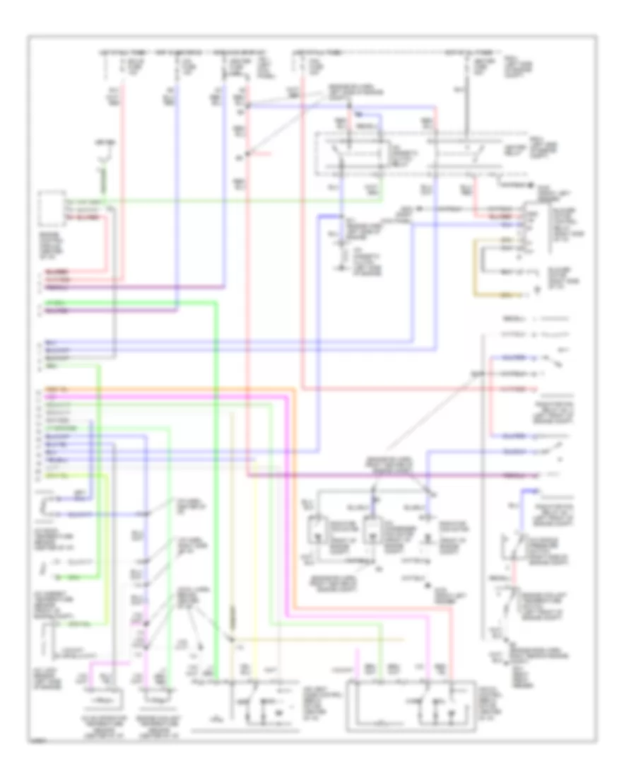
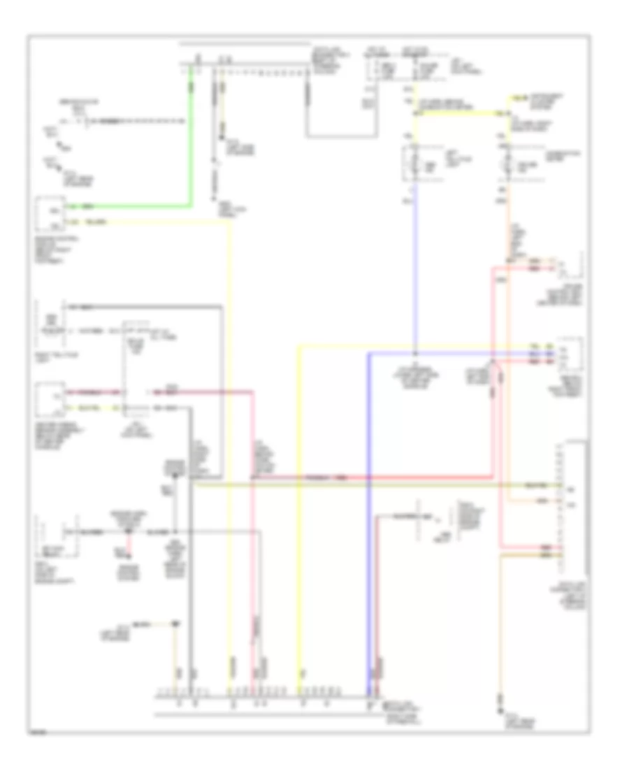
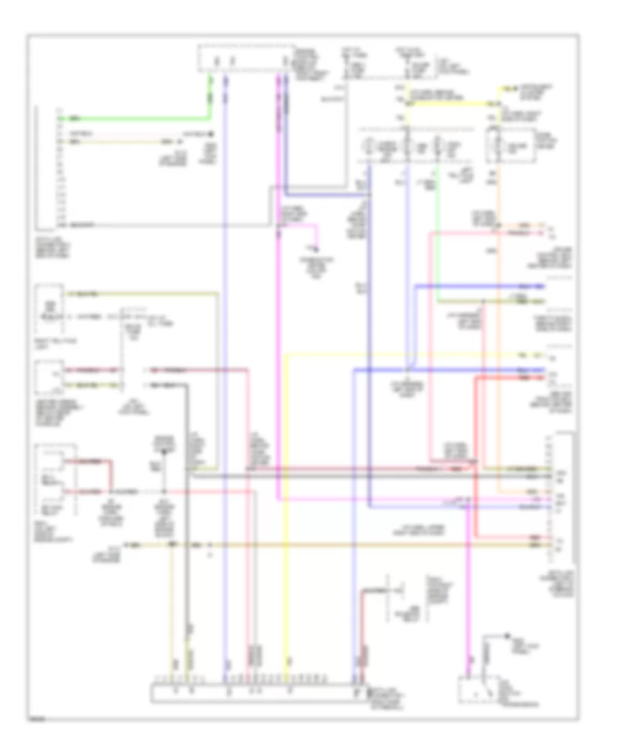
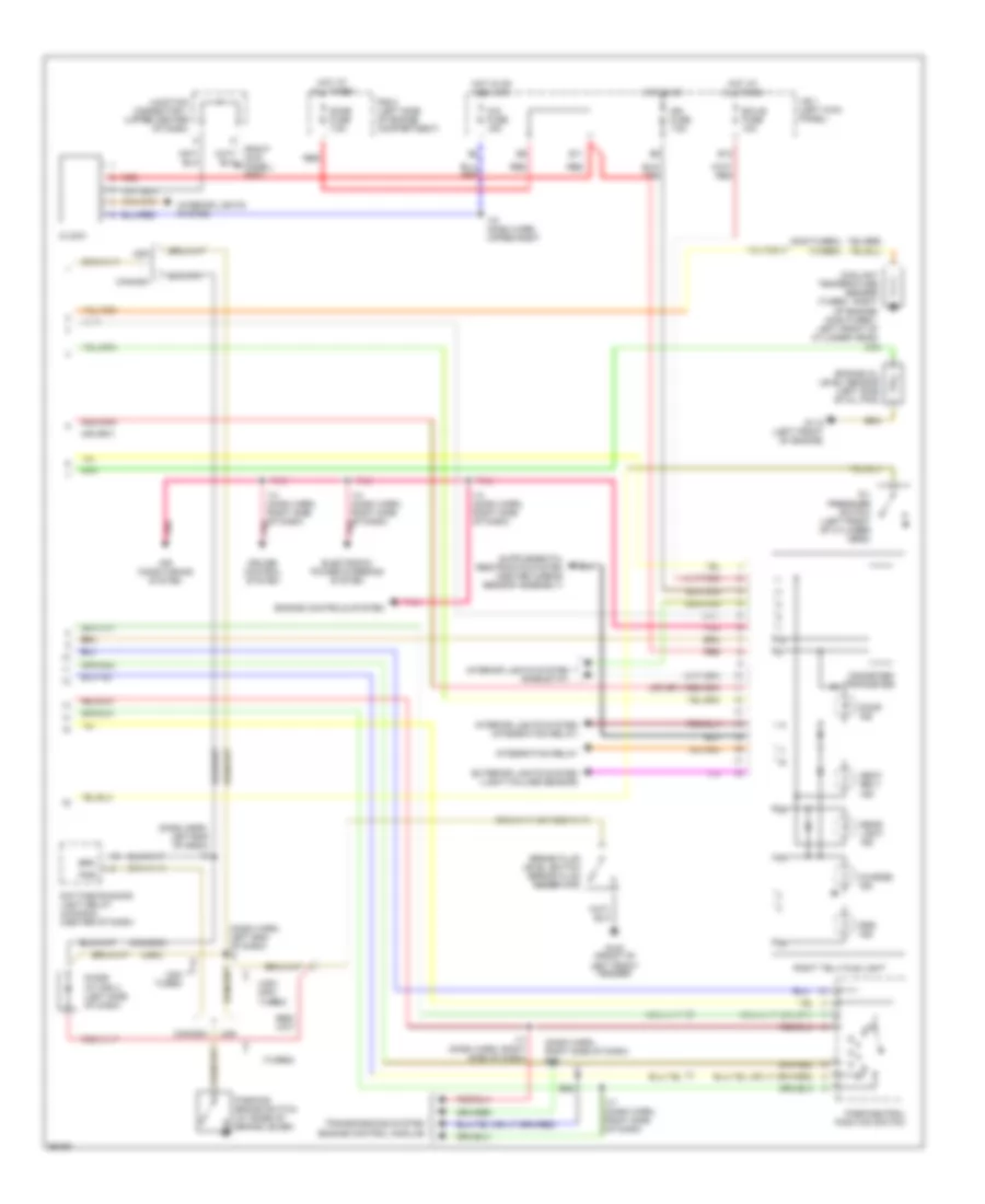
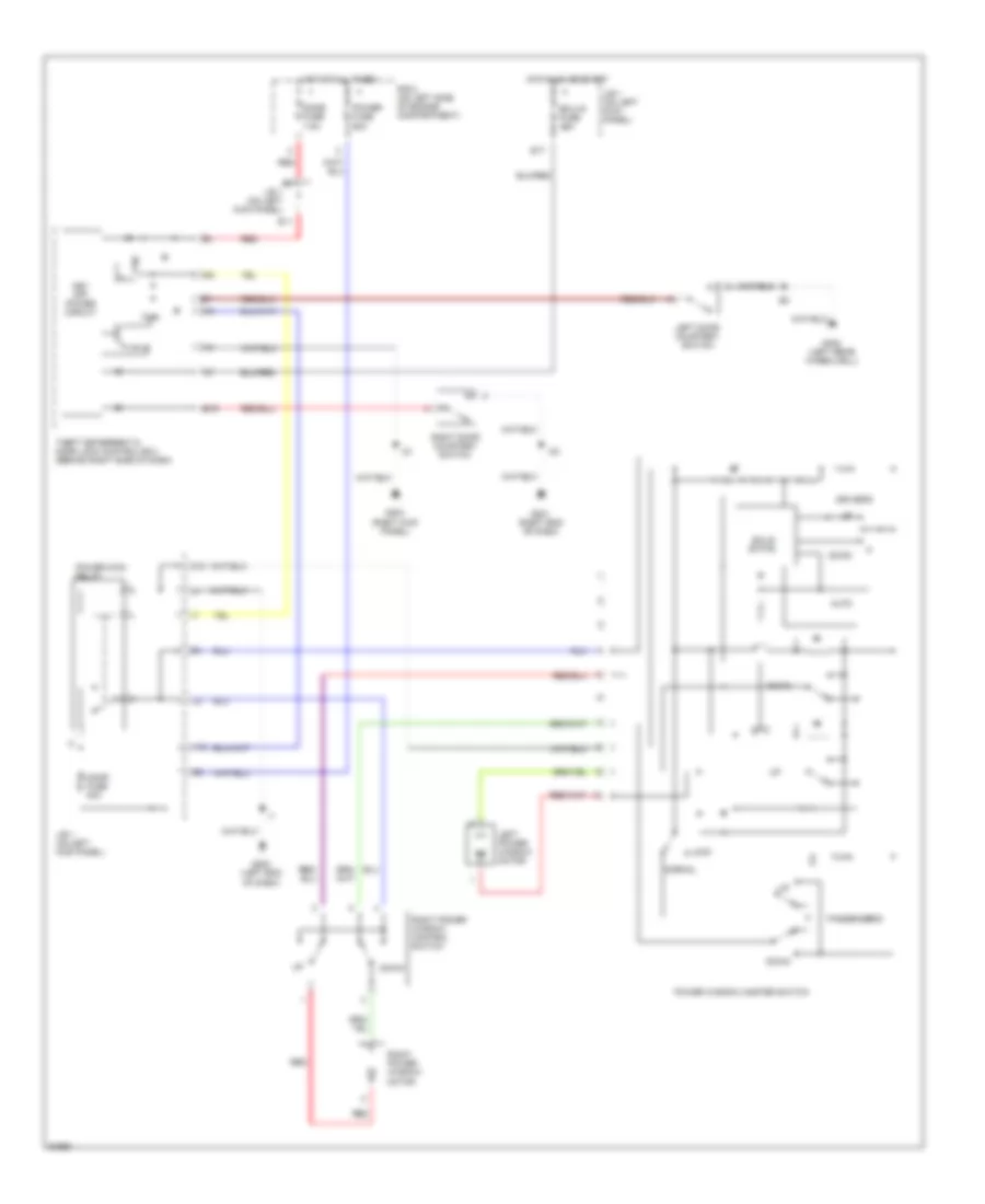
AIR CONDITIONING Air Conditioning Wiring Diagrams (1 of 2) for Toyota Supra 1997 List of elements for Air Conditioning Wiring Diagrams (1 of 2) for Toyota Supra 1997: 80 (i/p harn, behind center of i/p) (i/p harness, behind center of i/p) A/c A/c amplifier (center of i/p) A/c dual pressure switch (right side of engine compt) A/c solar sensor (left side of i/p) A/c- heater control panel A/c-in A/cs A10 A11 A12 A13 A14 A15 A16 A17 A18 Acc Air inlet control servo motor (right side of i/p) Auto B/l B10 B11 B12 Blw Def Defogger system F/d Face Fand-fand+ Foot Fresh Frs G101 (right front fender) G203 (right kick panel) Gnd H12 H13 I12 I25 Ig+ Ign Interior lights system Junction connector (center of i/p) M-h M-l M-m Maut Mdef Mfac Mfrs Mgc Mr/f Mrec Off Pnk Psw R-def R/d Rec Rec/frs Recirc Red Right telltale light (center of i/p) Rr-defog Spd Ssr+ Sw1 Sw2 Sw3 Sw4 Sw5 Sw6 Sw7 Tam Tpm Tset Ver1 Vss Air Conditioning Wiring Diagrams (2 of 2) for Toyota Supra 1997 List of elements for Air Conditioning Wiring Diagrams (2 of 2) for Toyota Supra 1997: 50 (cowl harn, behind center of i/p) (engine rm harn, front center of engine compt) (engine rm harn, left side of engine compt) (i/p harn, center of i/p) (i/p harn, right side of i/p) A/c ambient temperature sensor (front of engine compt) A/c condenser fan motor (front of engine compt) A/c evaporator temperature sensor (center of i/p) A/c lock sensor (left side of engine) A/c magnetic clutch (left side of engine) A/c magnetic clutch relay A/c room temperature sensor (center of i/p) A/c single pressure switch (right side of engine compt) Air mix control servo motor (center of i/p) Air vent mode control servo motor (center of i/p) Blower motor (right side of i/p) Blower motor control relay (right side of i/p) Cig fuse 15a Cool Def E11 (engine harn, left side of engine) E13 E5 (engine room harn, right rear of engine compt) Ecu-b fuse 10a Engine control module (center of i/p) Engine coolant temperature sensor (center of i/p) Engine coolant temperature switch (left front of engine compt) Face Fan fuse 30a G100 (front left fender) G101 (right front fender) G203 (right kick panel) Gnd Heater fuse 50a Heater fuse 7.5a Heater relay Hot at all times Hot in acc or on Hot in on or start I12 I13 I14 I19 Igniter J/b 1 (left kick panel) R/b 2 (left side of engine compt) Radiator fan motor (front of engine compt) Radiator fan relay no. 1 (left front of engine compt) Radiator fan relay no. 2 (left front of engine compt) Warm
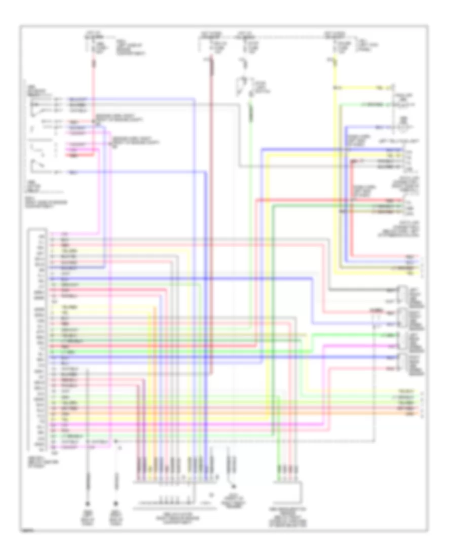
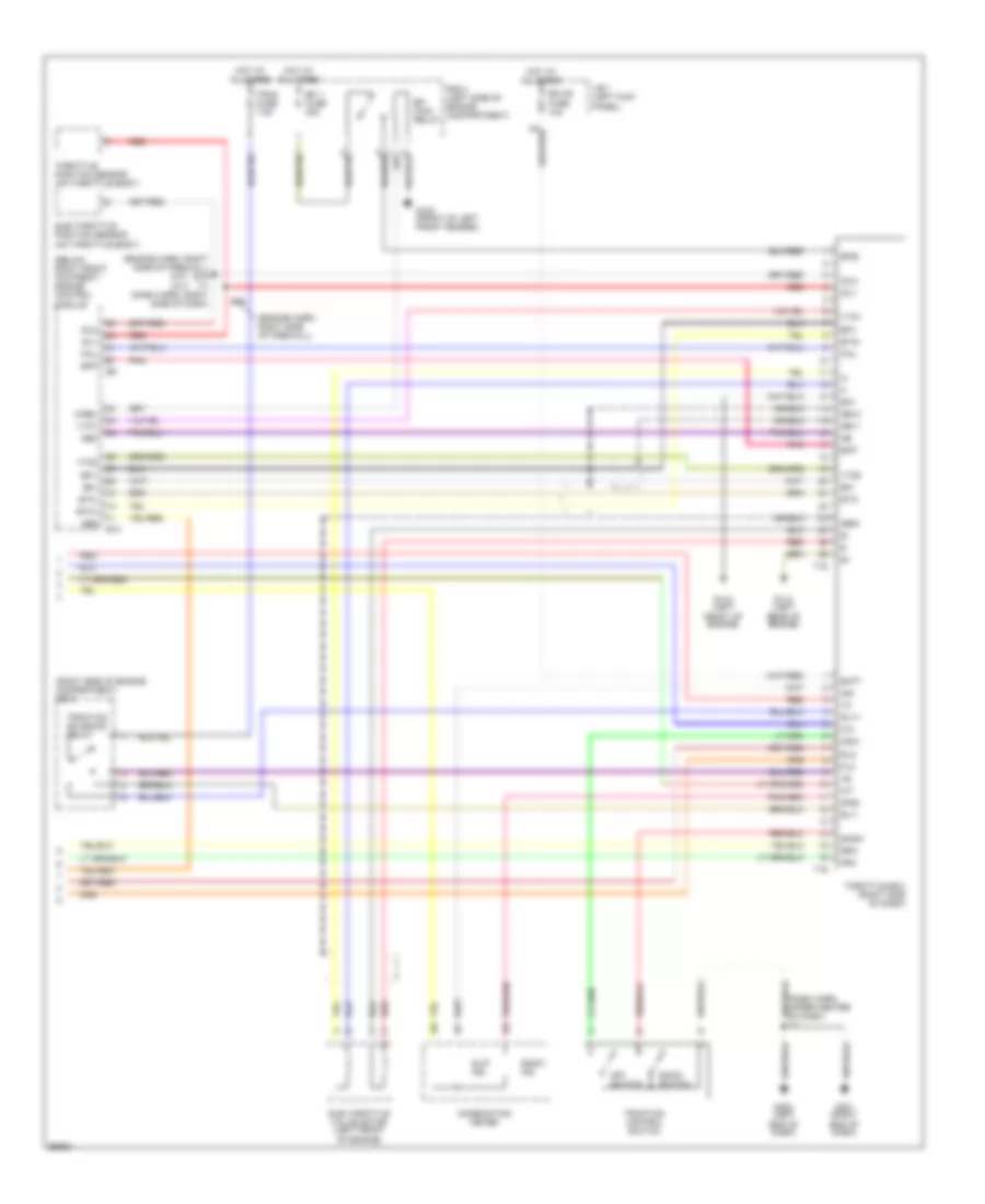
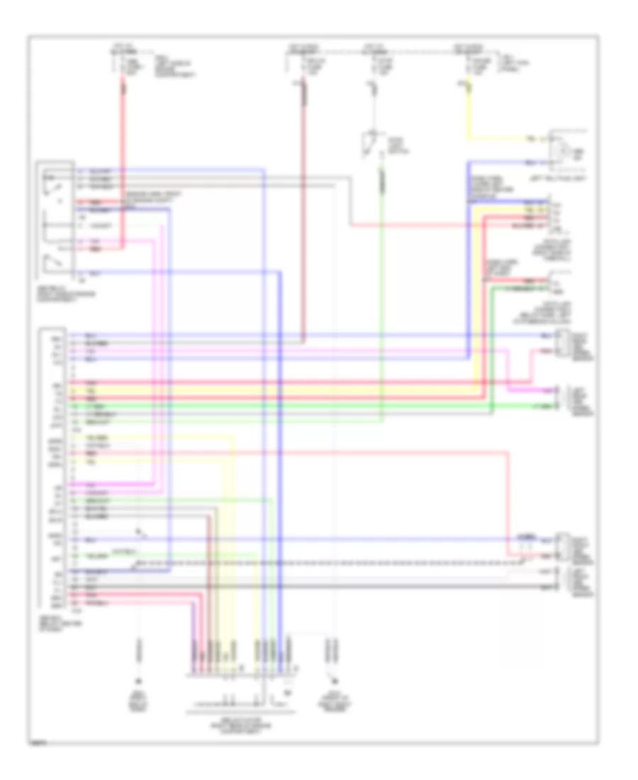
ANTI-LOCK BRAKES Anti-lock Brake Wiring Diagrams, with Traction Control (1 of 2) for Toyota Supra 1997 List of elements for Anti-lock Brake Wiring Diagrams, with Traction Control (1 of 2) for Toyota Supra 1997: 70 (dash harn, left end of dash) (dash harn, left end of dash) i2 (engine harn, right front of engine compt) e6 A20 A21 Abs Abs actuator (right rear of engine compartment) Abs deceleration sensor (below front console, forward of gear selector) Abs ecu (below center of dash) Abs fuse 1 60a Abs ind Abs motor relay Abs solenoid relay Ast D/g Data link connector 1 (right side of firewall) Data link connector 2 (below dash, left of steering column) Ecu-ig fuse 10a Exo Fl+ Fl- Flo Fr+ Fr- Fro G101 (front of right front fender) G201 (right end of dash) G202 (left end of dash) Gauge fuse 10a Ggnd Gl1 Gl2 Gnd1 Gnd2 Hot at all times Hot in run or start I14 I18 Ig1 J/b 1 (left kick panel) Left front abs speed sensor Left rear abs speed sensor Left telltale light Opa Pnk R/b 2 (left side of engine compartment) R/b 5 (right side of engine compartment) Red Right front abs speed sensor Right rear abs speed sensor Rl+ Rl- Rlo Rr+ Rr- Rro Sflh Sflr Sfrh Sfrr Shield Srlh Srlr Srrh Srrr Stop fuse 15a Stop light switch Stp Trac off ind Vgs Anti-lock Brake Wiring Diagrams, with Traction Control (2 of 2) for Toyota Supra 1997 List of elements for Anti-lock Brake Wiring Diagrams, with Traction Control (2 of 2) for Toyota Supra 1997: 65 (below right front footrest) engine control module (engine harn, right side of firewall) (engine harn, right side of firewall) e16 i17 (dash harn, right side of dash) (m/t) (a/t) (right side of engine compartment) r/b 5 Abs Batt Combination meter Csw E10 E16 Ecu-b fuse 10a Efi 1 fuse 30a Efi main relay Efi+ Efi- Efib Efif Eo1 Etc+ Etc- Fail Flo Fro G100 (front of left front fender) G110 (left front of engine) G114 (left rear of engine) G201 (right end of dash) G202 (left end of dash) Ge11 Ge12 Geo1 Hot at all times Idl1 Idl2 Ind J/b 1 (left kick panel) M-rel Neo Off switch Pnk R/b 2 (left side of engine compartment) Red Rlo Rly+ Rly- Rro Shield Sind Slip ind Snow Snow ind Snow switch Sub throttle position sensor (on throttle body) Sub throttle valve motor (left front of engine) T15 T16 Throttle ecu (right side of dash) Throttle position sensor (on throttle body) Trac fuse 7.5a Traction control switch Traction solenoid relay Vta1 Vto1 Vto2 Anti-lock Brake Wiring Diagrams, without Traction Control for Toyota Supra 1997 List of elements for Anti-lock Brake Wiring Diagrams, without Traction Control for Toyota Supra 1997: 51 (dash harn, left end of dash) i2 (dash harn, lower left side of center console) i9 (engine harn, front of engine compt) e18 A18 A19 Abs Abs actuator (right rear of engine compartment) Abs ecu (below center of dash) Abs fuse 1 60a Abs ind Abs relay (right side of engine compartment) Ast D/g Data link connector 1 (right side of firewall) Data link connector 2 (below dash, left of steering column) Ecu-ig fuse 10a Fl+ Fl- Fr+ Fr- G101 (front of right front fender) G201 (right end of dash) Gauge fuse 10a Gnd1 Gnd2 Hot at all times Hot in run or start Ig1 J/b 1 (left kick panel) Left front abs speed sensor Left rear abs speed sensor Left telltale light Pnk R/b 2 (left side of engine compartment) Red Right front abs speed sensor Right rear abs speed sensor Rl+ Rl- Rr+ Rr- Sflh Sflr Sfrh Sfrr Shield Srh Srr Stop fuse 15a Stop light switch Stp
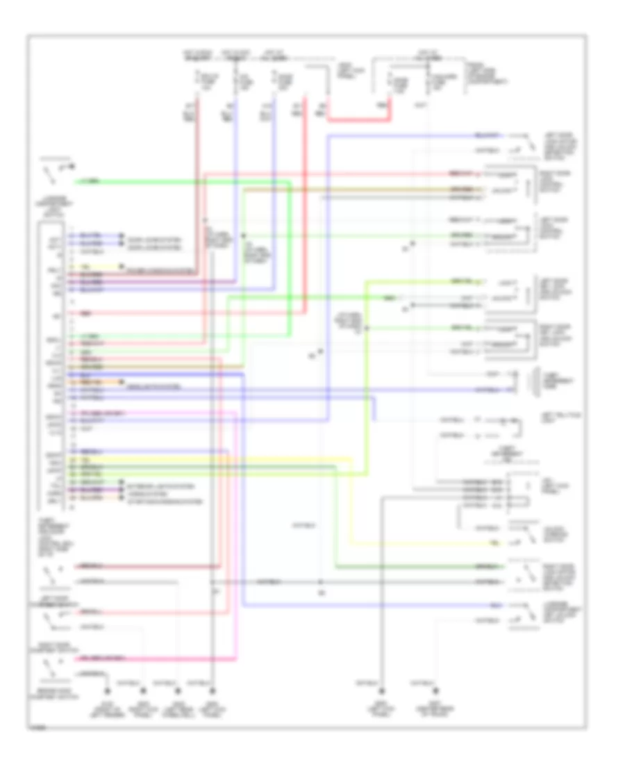
ANTI-THEFT Anti-theft Wiring Diagram for Toyota Supra 1997 List of elements for Anti-theft Wiring Diagram for Toyota Supra 1997: 73 (i/p harn, right end of dash) i21 +b1 +b2 Acc Act+ Act- Cig fuse 15a D10 Dome fuse 7.5a Door fuse 30a Door locks system Dswd Dswh Dswl Dswp E11 E17 E18 Ecu-ig fuse 10a Engine hood courtesy switch Exterior lights system G100 (front of left fender) G200 (left kick panel) G203 (right kick panel) G402 (left rear wheelwell) G407 (center rear of trunk) H15 Haz-horn fuse 15a Head Headlights system Horn Horns system Hot at all times Hot in acc or run Hot in run or start I19 (i/p harn, right end of dash) I21 I21 (i/p harn, right end of dash) Ind J/b #1 (left kick panel) J/b 1 (left kick panel) K12 Ksw Left door courtesy switch Left door key lock and unlock switch Left door lock control switch Left door lock motor and unlock detection switch Left telltale light Lock Lswd Lswp Lug Luggage compartment key unlock switch Luggage compartment light switch Power windows system Prly R/b #2 (left side of engine compartment) Red Right door courtesy switch Right door key lock and unlock switch Right door lock control switch Right door lock motor and unlock detection switch Srly Starting/charging system Tail Theft deterrent and door lock control ecu (right side of i/p) Theft deterrent horn Theft deterrent ind Ul1 Ul12 Ul3 Unlock Unlock warning switch
COMPUTER DATA LINES
3.0L 3.0L Non-Turbo, Computer Data Lines for Toyota Supra 1997 List of elements for 3.0L Non-Turbo, Computer Data Lines for Toyota Supra 1997: 50 (behind glove box) j/c 2 (engine harn, forward of r/b 2) e20 (i/p harn, behind comb- ination meter) i5 (i/p harn, left end of dash) i2 (i/p harn, right side of dash) i14 (right side of firewall) A/d A20 Abs ecu (below right front footrest) Abs ind Abs relay C14 Center airbag sensor assembly (below rear of center console) Combination meter Connector 1 Cruise control ecu (behind left center of dash) Cruise ind Data link connector 2 (left of steering column) Data link connector 3 (left of steering bat column) Data link wb E12 E13 E26 (engine harn, left rear of engine block) E28 Ecu-b fuse 10a Efi main relay Engine control module (below right front footrest) Engine control system G112 (left side of engine) G114 (left rear of engine) G200 (left kick panel) Gauge fuse 10a Hot at all times Hot in on or start I14 (i/p harn, right side of dash) I2 (i/p harn, left end of dash) I9 (i/p harness, lower left side of center console) Ig- Instrument cluster system J/b 1 (on left kick panel) Left telltale light Obd 2 fuse 7.5a R/b 2 (on left side of engine compt) R/b 5 (0n right side of engine compt) Red Right telltale light Sdl Shield Srs ind Te1 3.0L Turbo, Computer Data Lines for Toyota Supra 1997 List of elements for 3.0L Turbo, Computer Data Lines for Toyota Supra 1997: 67 (a/t only) (i/p harn, behind comb- ination meter) i5 (i/p harn, left end of dash) (i/p harn, left end of dash) i2 (i/p harn, right end of dash) i21 (i/p harn, right side of dash) i14 (i/p harn, upper right end of dash) (mil) (right side of firewall) A/d A11 A20 A21 A28 Abs and traction ecu (behind center of dash) Abs ind Abs solenoid relay B10 C14 Center airbag sensor assembly (below rear of center console) Check engine Comb- ination meter Combination meter (o/d off ind) Cruise control ecu (behind left center of dash) Cruise ind Data link connector 2 (left of steering column) Data link connector 3 (behind left end of dash) Data link wb connector 1 E12 E13 E13 (engine harn, left side of engine block) E16 E7 (engine harn, forward of r/b 2) Ect Ecu-b fuse 10a Efi 2 relay Efi main relay Engine control module (below right front footrest) Engine control system G112 (left side of engine) G200 (left kick panel) Gauge fuse 10a Hot at all times Hot in on I14 (i/p harn, right side of dash) I18 I2 (i/p harness, left end of dash) I4 (i/p harness, left end of dash) I5 (i/p harn, behind comb- ination meter) Ind Instrument cluster system J/b 1 (on left kick panel) Left telltale light O/d main switch (on transmission) Obd ii fuse 7.5a Od2 Opa Or start R/b 2 (on left side of engine compt) R/b 5 (0n right side of engine compt) Red Right telltale light Sdl Srs ind Te1 Throttle ecu (behind right side of dash) Trac off ind
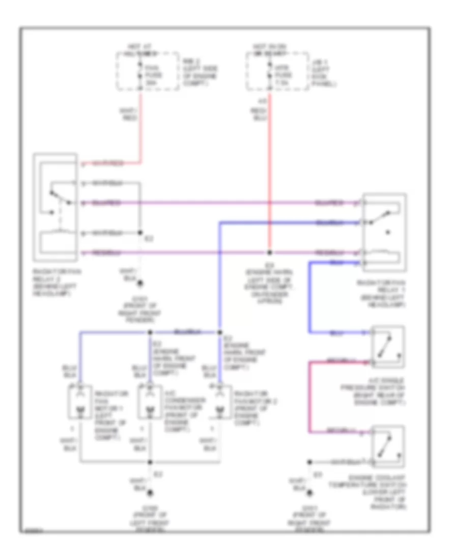
COOLING FAN Cooling Fan Wiring Diagram for Toyota Supra 1997 List of elements for Cooling Fan Wiring Diagram for Toyota Supra 1997: 17 A/c condenser fan motor (front of engine compt) A/c single pressure switch (right rear of engine compt) Compt) E9 (engine harn, left side of engine compt, on fender apron) Engine coolant temperature switch (lower left front of radiator) Fan fuse 30a G100 (front of left front fender) G101 (front of right front fender) Hot at all times Hot in on or start Htr fuse 7.5a J/b 1 (left kick panel) R/b 2 (left side of engine compt) Radiator fan motor 1 (left front of engine compt) Radiator fan motor 2 (front of engine compt) Radiator fan relay 1 (behind left headlamp) Radiator fan relay 2 (behind left headlamp)
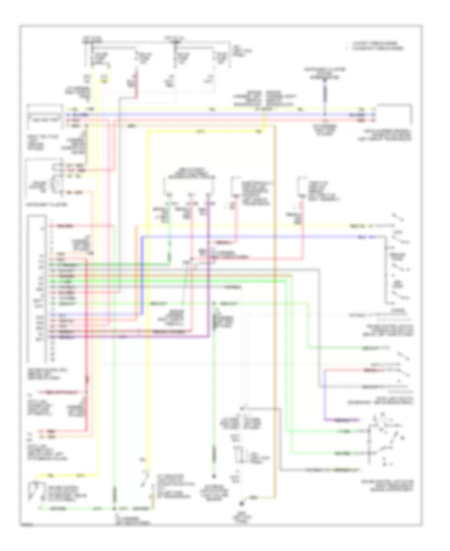
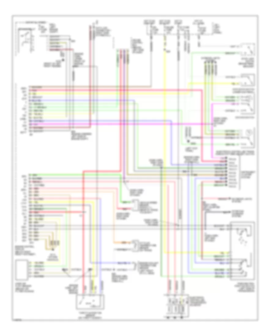
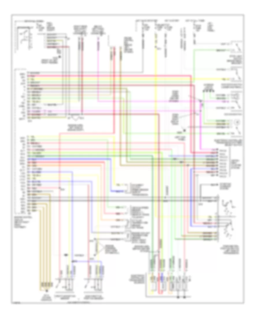
CRUISE CONTROL Cruise Control Wiring Diagram for Toyota Supra 1997 List of elements for Cruise Control Wiring Diagram for Toyota Supra 1997: 67 (a/t) (below right front footrest) engine control module (engine harness, left rear of engine block) e14 (engine harness, right rear of engine block) e28 (engine harness, right side of firewall) (i/p harn, left end of dash) (i/p harness, left end of dash) (i/p harness, right side of dash) (m/t) 2jz-ge non-turbocharged 2jz-gte turbocharged A/d A/t indicator light switch (d position switch) (a/t) (on left side of transmission) A10 A8 b2 B11 Batt Cancel Ccs Cms Cruise control actuator (right rear side of engine compartment) Cruise control clutch switch (on bracket, above clutch pedal) Cruise control ecu (behind left center of dash) Cruise control ind Cruise control switch (combination switch) (below left side of dash) Data link connector 1 (right side of firewall) Data link connector 2 (below dash, left of steering column) E10 E12 E16 Ect Ecu-b fuse 10a Ecu-ig fuse 10a Electronically controlled transmission solenoid (left side of transmission) Exterior lights system (light failure sensor) G200 (left kick panel) Gauge fuse 10a Gnd H12 H13 Hot at all times Hot in on and start I10 I14 I17 I4 (i/p harness, left end of dash) I4 i9 (i/p harn, right end of dash) I8 (i/p harness, behind combination meter) Idl Idl1 Instrument cluster Instrument cluster system (speedometer) J/b 1 (left kick panel) Main Od1 Odo and trip Pnk Red Resume/ accel Right telltale light (center of dash) Set/ coast Spd Stop fuse 15a Stop light switch (on bracket, above brake pedal) Stp- Throttle position sensor (on throttle body assembly) Vehicle speed sensor 1 (combination meter) (left side of transmission)
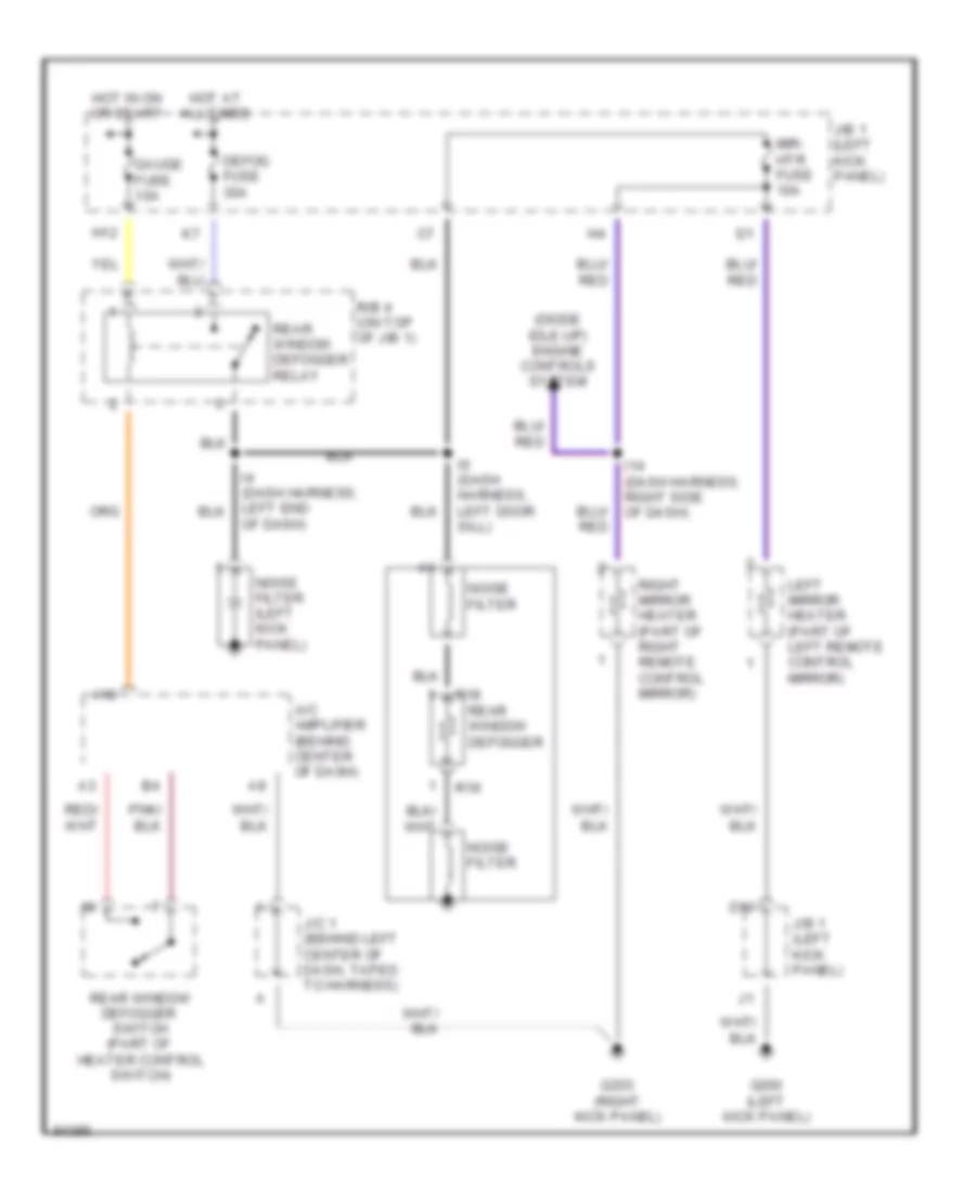
DEFOGGERS Defogger Wiring Diagram for Toyota Supra 1997 List of elements for Defogger Wiring Diagram for Toyota Supra 1997: 27 (diode idle-up) engine controls system A/c amplifier (behind center of dash) A18 D10 Defog fuse 30a G200 (left kick panel) G203 (right kick panel) Gauge fuse 10a H12 Hot at all times Hot in on or start I14 (dash harness, right side of dash) I6 (dash harness, left door sill) J/b 1 (left kick panel) J/c 1 (behind left center of dash, taped to harness) Left mirror heater (part of left remote control mirror) Mir- htr fuse 10a Noise filter Noise filter (left kick panel) Of dash) R/b 4 (on top of j/b 1) R18 R19 Rear window defogger Rear window defogger switch (part of heater control switch) Rear window defogger relay Right mirror heater (part of right remote control mirror)
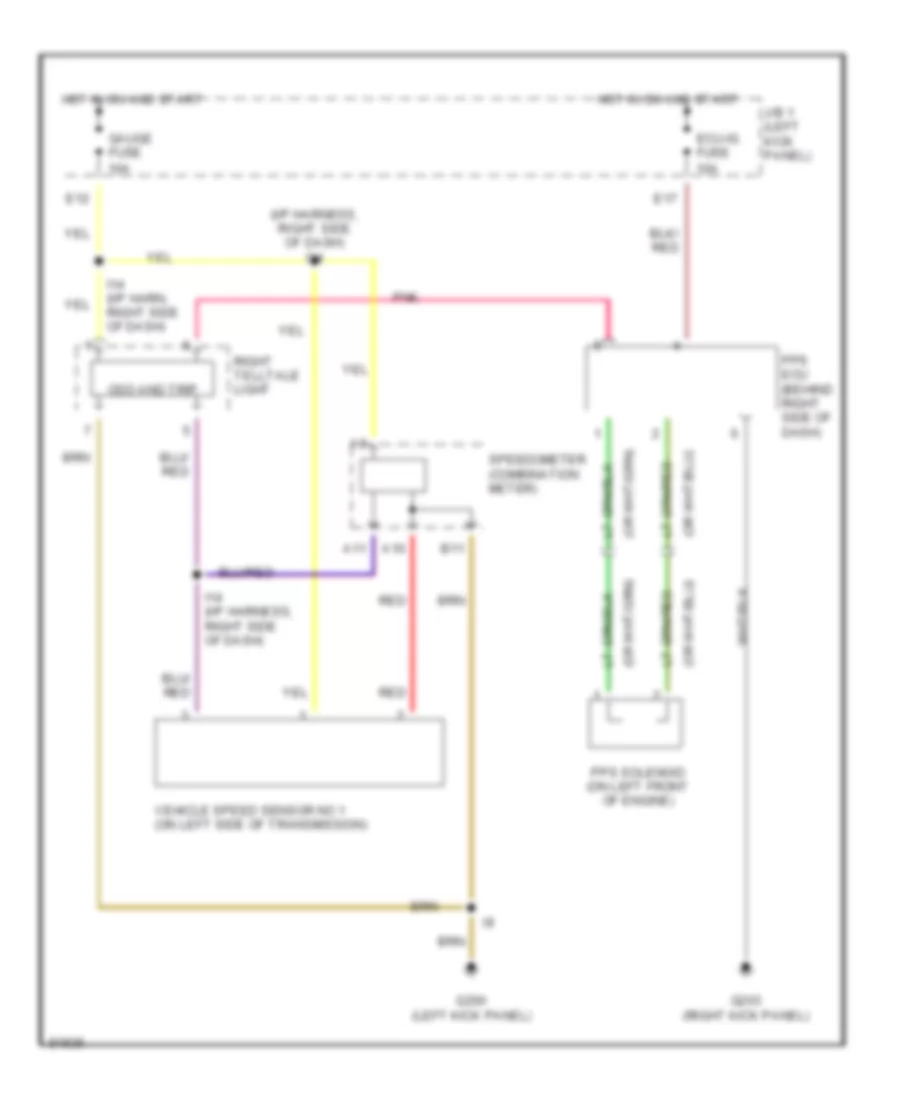
ELECTRONIC POWER STEERING Electronic Power Steering Wiring Diagram for Toyota Supra 1997 List of elements for Electronic Power Steering Wiring Diagram for Toyota Supra 1997: 22 (i/p harness, right side of dash) i14 A10 A11 B11 E12 E17 Ecu-ig fuse 10a G200 (left kick panel) G203 (right kick panel) Gauge fuse 10a Hot in on and start I14 (i/p harn, right side of dash) I14 (i/p harness, right side of dash) J/b 1 (left kick panel) Odo and trip Pnk Pps ecu (behind right side of dash) Pps solenoid (on left front of engine) Red Right telltale light Speedometer (combination meter) Vehicle speed sensor no 1 (on left side of transmission)
ENGINE PERFORMANCE
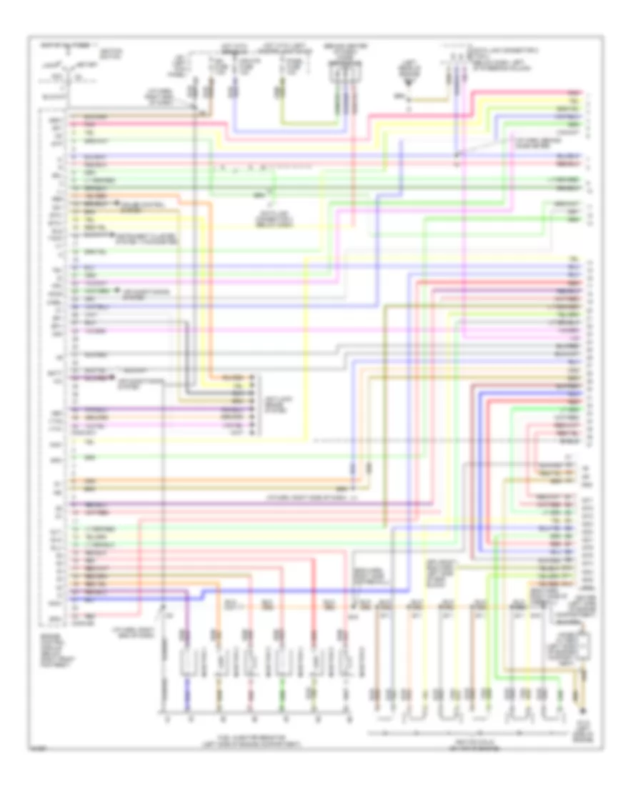
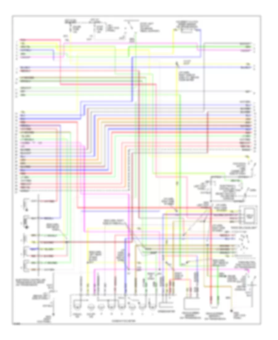
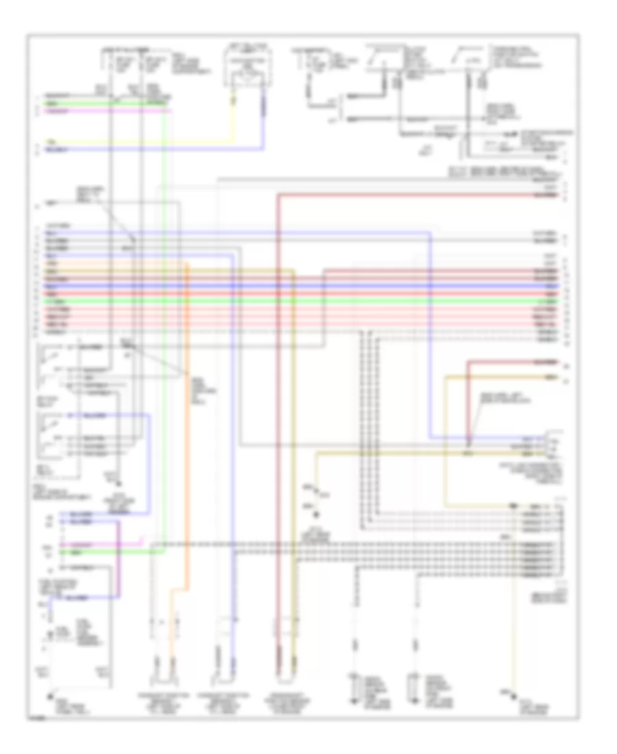
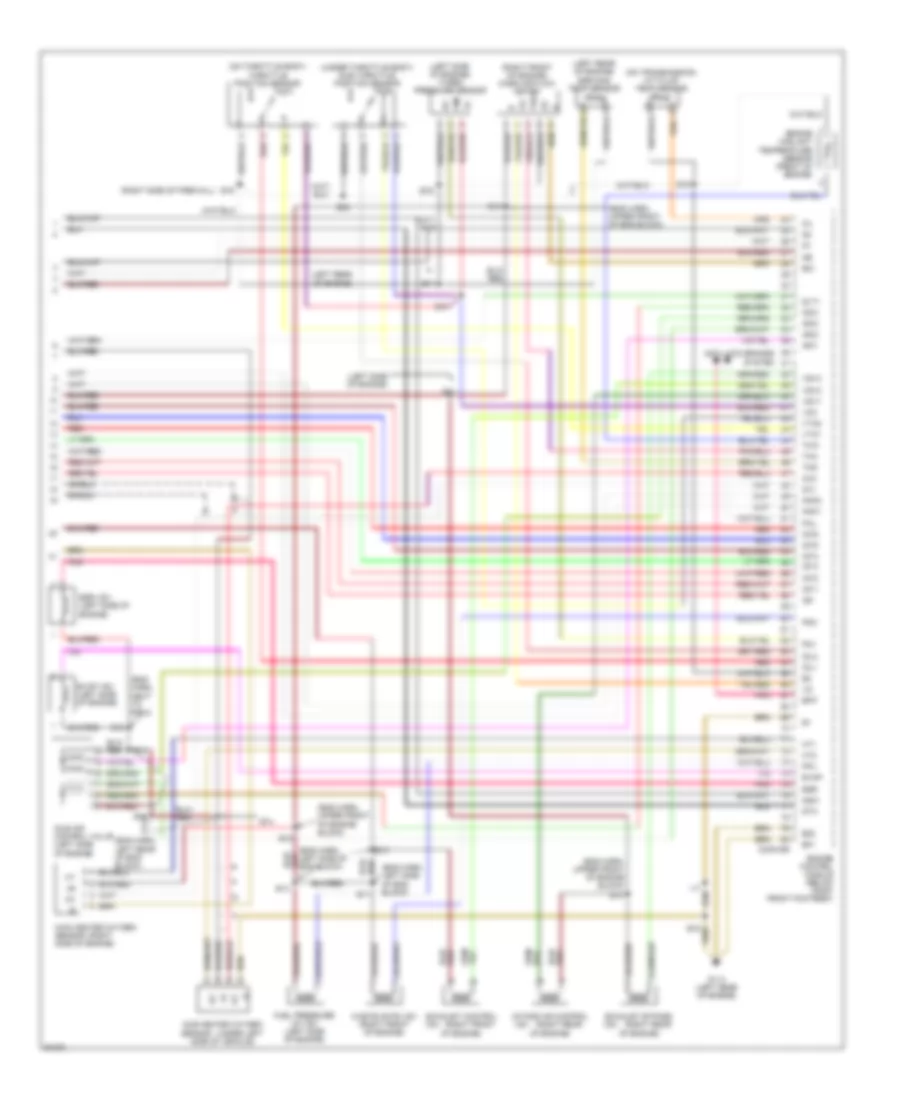
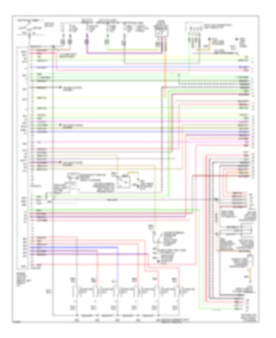
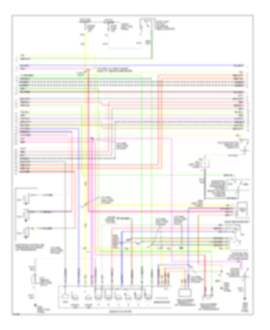
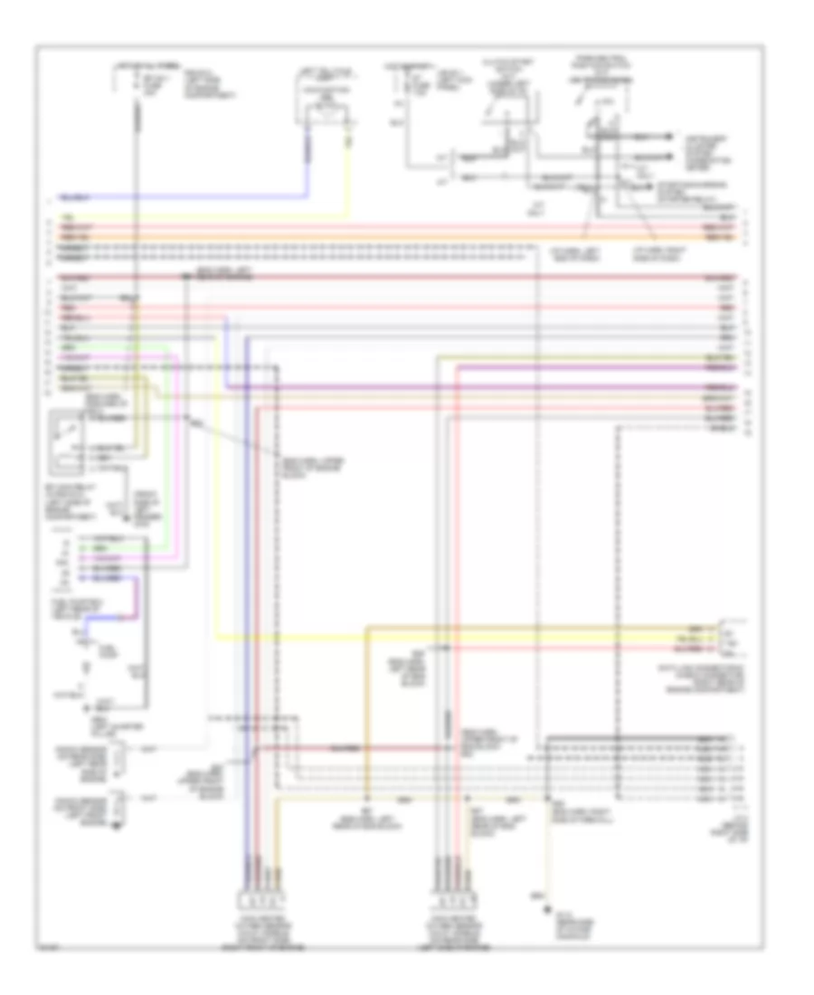
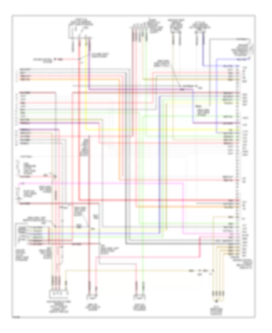
3.0L 3.0L Turbo, Engine Performance Wiring Diagrams (1 of 4) for Toyota Supra 1997 List of elements for 3.0L Turbo, Engine Performance Wiring Diagrams (1 of 4) for Toyota Supra 1997: 95 (behind center of dash) diode (for idle-up) (eng harn, right side of firewall) (i/p harn, behind comb meter) (i/p harn, right end of dash) (i/p harn, right side of dash) (left rear of engine) g114 (splice e11: eng harn, left side of eng block) (tachometer) A/c Abs Acc Acmg Air conditioning system Anti-lock brake system B10 B11 B12 Batt Conn e10 Conn e9 Cruise control system Data link connector 2 (tdcl) (below dash, left of steering column) Data link connector 3 (below dash) E11 E16 Ect Efi+ Efi- Els Engine control module (below right front footrest) Etc+ Etc- Fpc Fuel injector resistor (left side of engine compartment) G1- G112 (left side of engine) Gnd Hot at all times Hot with defog on Hot with light control switch on I17 I20 Igc1 Igc2 Igc3 Igc4 Igc5 Igc6 Igf Ign fuse 7.5a Igniter (left side of engine compartment) Ignition coils (on top of engine) Ignition switch Igsw Igt1 Igt2 Igt3 Igt4 Igt5 Igt6 Injector 1 Injector 2 Injector 3 Injector 4 Injector 5 Injector 6 Instrument cluster system J/b 1 (left kick panel) Lock M-rel Mir-htr fuse 10a Nco+ Nco- Ne- Neo Noise filter (left side of engine compart- ment) Od1 Od2 Panel fuse 10a Pnk Red Sdl Shield Sln- Slt- Slu- Sp1 Sp2+ Sp2- Start Stp Taco Te1 Vta1 Vta2 3.0L Turbo, Engine Performance Wiring Diagrams (2 of 4) for Toyota Supra 1997 List of elements for 3.0L Turbo, Engine Performance Wiring Diagrams (2 of 4) for Toyota Supra 1997: 55 (eng harn, center of dash) (eng harn, left rear of eng block) (eng harn, right side of firewall) (i/p harn, right end of dash) (i/p harn, right side of dash a/t, behind comb meter) (i/p harn, right side of dash) (right of dash) (right side of dash) A10 A11 A12 A13 B10 B11 C11 Combination meter Cruise control system E12 E14 E16 E17 Electronic controlled pattern select switch (on center console) Electronic controlled transmission solenoid (on transmission) G200 (left kick panel) G203 (right kick panel) Gauge fuse 10a H13 Hot at all times Hot in on or start I10 I14 I14 a/t i8 m/t I17 I18 I21 J/b 1 (left kick panel) J/c 1 (behind left side of dash) Kick down switch (1998) (under left side of dash) Man Manual ind Norm O/d direct clutch speed sensor (on transmission) O/d main switch (on center console) O/d off ind Odo & trip Park/neutral position switch (on transmission) Pnk Red Right telltale light Shield Speedometer Stop fuse 15a Stop light switch (on brake pedal support) Vehicle speed sensor 1 (on transmission) Vehicle speed sensor 2 (on transmission) 3.0L Turbo, Engine Performance Wiring Diagrams (3 of 4) for Toyota Supra 1997 List of elements for 3.0L Turbo, Engine Performance Wiring Diagrams (3 of 4) for Toyota Supra 1997: 45 (eng harn, forward of r/b 2) (eng harn, left side of eng block) (eng harn, next to r/b 2) (eng harn, right side of firewall) e16 A/t A/t only Camshaft position sensor 1 (left side of cyl head) Camshaft position sensor 2 (left side of cyl head) Clutch start switch (m/t only) (above clutch pedal) Crankshaft position sensor (lower front of engine) Data link connector 1 (check connector) (right side of firewall) E12 E13 E14 E16 E17 a/t (eng harn, center of dash) (eng harn, right side of firewall) e16 m/t Efi 2 relay Efi main relay Efi no.1 fuse 30a Efi no.2 fuse 30a Fpc Fuel pump Fuel pump ecu (left rear of vehicle) Fuel pump/ fuel sender assembly G100 (front side of left fender) G114 (left rear of engine) G402 (left rear wheel well) Hot at all times Hot in start J/b 1 (left kick panel) J/c 2 (behind right side of dash) Knock sensor (on front side) (left side of engine) Knock sensor (on rear side) (left side of engine) Left telltale light M/t M/t only Malfunction ind P/n Park/neutral position switch (a/t only) (on transmission) R/b 2 (left side of engine compartment) Red Shield St fuse 7.5a Starting/charging system (starter relay) Te1 3.0L Turbo, Engine Performance Wiring Diagrams (4 of 4) for Toyota Supra 1997 List of elements for 3.0L Turbo, Engine Performance Wiring Diagrams (4 of 4) for Toyota Supra 1997: 91 (eng harn, left rear of eng block) (eng harn, left side of eng block) (eng harn, next to r/b 2) (eng harn, upper front of eng block) (eng harn, upper front of engine block) (left rear of engine) (left side of engine) turbo pressure sensor (left side of engine) (on throttle body) (on transmission) a/t fluid temp sensor (right (right front (right front of engine) mass air flow meter (right rear (right side of firewall) (under left (under throttle body) sub throttle position sensor Anti-lock brakes system Conn e9 E01 E02 E10 E11 E12 E13 E14 E16 E21 Efif Egr Egr gas temp sensor Egr vsv (left side of engine) Engine control module (below right front footrest) Engine coolant temperature sensor (front of engine) Evap Evap vsv (left side of engine) Exhaust bypass Exhaust control Fail Fpu Fuel pressure up vsv (left side of engine) G114 (left rear of engine) Ht1 Ht2 I17 Idl1 Idl2 Idle air control valve (left side of engine) Igf Igt1 Igt2 Igt3 Igt4 Igt5 Igt6 Intake air control Isc1 Isc2 Isc3 Isc4 Knk1 Knk2 Main heated oxygen sensor side of engine) Nsw Of engine) Oil Ox1 Ox2 Pim Pm1 Pmc Pnk Red Sensor Shield Side of vehicle) Slt+ Sta Sub heated oxygen Tha Thg Throttle position sensor Thw Vcc Vsv Vsv1 Vsv2 Vsv3 Vta1 Vta2 Waste gate vsv (right front of engine) 3.0L, Engine Performance Wiring Diagrams (1 of 4) for Toyota Supra 1997 List of elements for 3.0L, Engine Performance Wiring Diagrams (1 of 4) for Toyota Supra 1997: 79 #10 #20 #30 #40 #50 #60 (eng harn, right side of fire- wall) (eng harn, right side of firewall) (engine harness, right side of firewall) (i/p harn, left kick panel) (i/p harn, right end of dash) (left rear of engine) g114 (rear side of intake manifold) g112 A/c Acc Acmg Air conditioning system Bat Batt C14 Conn e10 Conn e9 Crankshaft position sensor (front of engine) Cruise control system Data link connector 3 (left side of i/p) Diode (dle-up) (behind left side of i/p) Distributor (right front of engine) E22 (eng harn, upper right front of eng block) E28 Els Engine control module (below left side of i/p) Ext Fpc G112 (left side of engine) G131 (front side of intake manifold) G200 (left kick panel) Hot at all times Hot with defog on Hot with light control switch on Ht3 I20 Igf Ign fuse 7.5a Igniter (left side of engine compartment) Ignition coil (right side of engine compartment) Ignition switch Igsw Igt Injector no.1 Injector no.2 Injector no.3 Injector no.4 Injector no.5 Injector no.6 J/b no.1 (left kick panel) Lock M-rel Mir-htr fuse 10a Nca Ne2+ Ne2- Noise filter (right side of engine compartment) Obd 2 fuse 7.5a Od1 Od2 Ox3 Panel fuse 10a Pnk Power steering pressure switch (left front of engine compt) Power steering pressure switch (right side of engine compt) Red Sdl Shield Sp1 Sp2+ Sp2- Start Stp Te1 3.0L, Engine Performance Wiring Diagrams (2 of 4) for Toyota Supra 1997 List of elements for 3.0L, Engine Performance Wiring Diagrams (2 of 4) for Toyota Supra 1997: 54 (eng harn, right side of fire- wall) (i/p harn, a/t: right side of dash, m/t: behind comb meter) (i/p harn, right end of dash) (i/p harn, right side of dash) (i/p harn, right side of fire- wall) A10 A11 A12 A13 B10 B11 C11 C13 Combination meter Cruise control system E12 E28 Electronic controlled transmission pattern select switch (on center console) Electronic controlled transmission solenoid (on transmission) G200 (left kick panel) G203 (right kick panel) Gauge fuse 10a H13 Hot at all times Hot in on or start I10 I14 I14 a/t i8 m/t I17 I21 J/b 1 (left kick panel) J/b no.1 (left kick panel) J/c 1 (behind left side of i/p) Kick down switch (behind left side of i/p) Man Manual ind No.1 No.2 No.3 Norm O/d main switch (on center console) O/d off ind Odo & trip Park/neutral position switch (on transmission) Pnk Red Right telltale light Shield Speedometer Stop fuse 15a Stop light switch (on brake pedal support) Tach Vehicle speed sensor no.1 (on transmission) Vehicle speed sensor no.2 (on transmission) 3.0L, Engine Performance Wiring Diagrams (3 of 4) for Toyota Supra 1997 List of elements for 3.0L, Engine Performance Wiring Diagrams (3 of 4) for Toyota Supra 1997: 49 (eng harn, forward of r/b 2) (eng harn, left rear of eng block) (eng harn, left rear of engine) (eng harn, right side of firewall) (eng harn, upper front of eng block) e23 (eng harn, upper front of engine block) (front side of left fender) g100 (i/p harn, left end of dash) (i/p harn, right side of dash) A/t A/t only Clutch start switch (a/t) (under left side of i/p) Data link connector #1 (check connector) (right rear of engine compartment) E20 E23 E23 (eng harn, upper front of engine block) E26 E27 (eng harn, left rear of eng block) E28 Efi main relay (in r/b no.2) (left side of engine compartment) Efi no.1 fuse 30a Fpc Fuel pump Fuel pump ecu (left rear of vehicle) G112 (rear side of intake manifold) G904 (left quarter pillar) Hot at all times Hot in start I17 Instrument cluster system (combination meter) J/b no.1 (left kick panel) J/c 2 (behind right side of i/p) Knock sensor (on front side) (left front engine) Knock sensor (on rear side) (left rear side of engine) Left telltale light M/t M/t only Main heated oxygen sensor (calif. models) (on front side) (right front of engine) Main heated oxygen sensor (calif. models) (on rear side) (left side of engine) Malfunction ind Nca P/n Park/neutral position switch (a/t) (on transmission) R/b no.2 (left side of engine compartment) Red Shield St fuse 7.5a Starting/charging system (starter relay) Te1 3.0L, Engine Performance Wiring Diagrams (4 of 4) for Toyota Supra 1997 List of elements for 3.0L, Engine Performance Wiring Diagrams (4 of 4) for Toyota Supra 1997: 58 (a/t) (eng harn, left rear of eng block) (eng harn, left rear of eng block) e26 (eng harn, left rear of eng) (eng harn, left side of eng block) (eng harn, right side of safety wall) (i/p harn, right side of dash) A/t fluid temp sensor (on transmission) Acis vsv (left rear of engine) Conn e9 Cruise control system E01 E02 E03 E24 E26 E28 E2g Egr Egr gas temp sensor (left rear of engine) Egr vsv (left side of engine) Engine control module (below right side of i/p) Engine coolant temp sensor (left front of engine) Evap Evap vsv (left rear of eng) Fpu Fuel pressure up vsv (left side of eng) G112 (rear side of intake manifold) Ht1 Ht2 I17 Idl1 Idle air control valve (right side of engine) Igf Igt Isc1 Isc2 Isc3 Isc4 Knk1 Knk2 Mass air flow meter (right side of engine compt) Nsw Ox1 Ox2 Pnk Red Shield Sta Sub heated oxygen sensor (calif. models) (under left side of vehicle) Tha Thg Tho Throttle position sensor (left side of engine) Thw Vcc Vsv2 Vta1
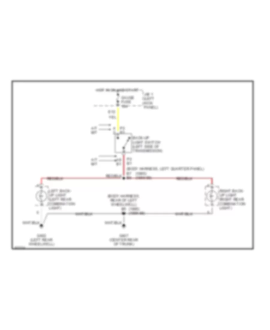
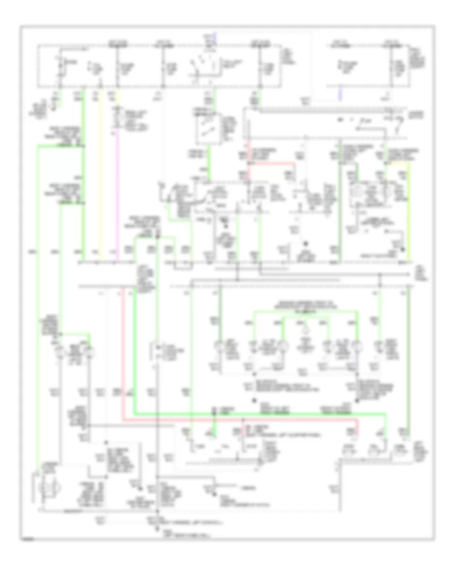
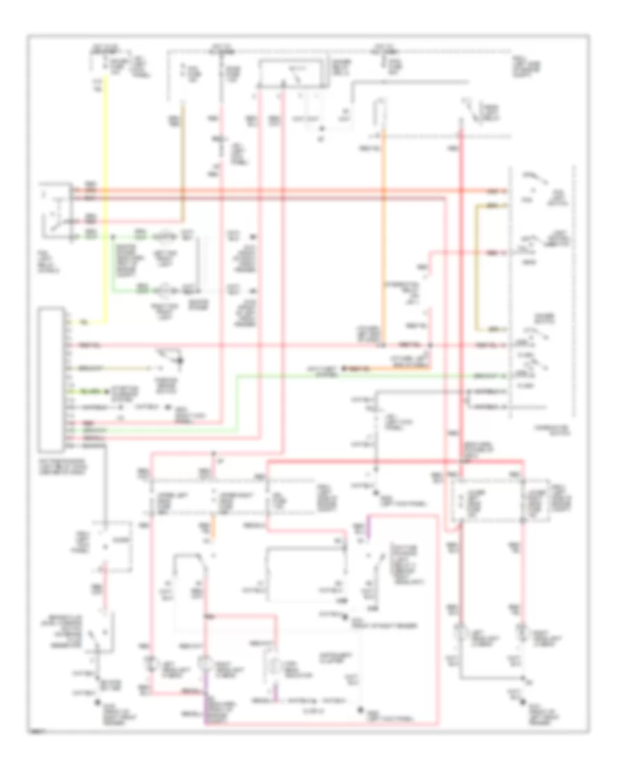
EXTERIOR LIGHTS Back-up Lamps Wiring Diagram for Toyota Supra 1997 List of elements for Back-up Lamps Wiring Diagram for Toyota Supra 1997: 15 (1995) (1996-98) (body harness, left quarter panel) b7 b6 (body harness, rear of left wheelwell) b5 b4 A/t m/t A8 b1 Back-up light switch (left side of transmission) E12 G402 (left rear wheelwell) G407 (center rear of trunk) Gauge fuse 10a Hot in on and start J/b 1 (left kick panel) Left back- up light (left rear combination light) P2 b1 Right back- up light (right rear combination light) Exterior Lamps Wiring Diagram for Toyota Supra 1997 List of elements for Exterior Lamps Wiring Diagram for Toyota Supra 1997: 78 (1995) (1996-98) (1995-96) (1996-98) (1996-98) (1995) (1997-98) (1998) (body harness center of rear bumper b8 (body harness, left door sill) (body harness, left side of rear bumper) b7 (body harness, rear of left rear wheelwell) (body harness, rear of left rear wheelwell) b5 b4 (body harness, rear of left rear wheelwell) b6 b5 (dash harness, lower left side of dash) i3 (engine harness, front of engine compt above radiator) e2 (or e18) (i/p harness, left end of dash) i2 (upper left center of dash) j/c 1 B10 (1996-98) (body har- ness, left side of hatch) B5 b4 B5 b6 (body har- ness, rear of left rear wheelwell) B6 b7 B6 b7 (body harness, left quarter panel) C10 C10 com- bina- tion meter C12 C16 Com- bin- ation switch Diode E12 E14 E19 From j/b 1 (diagram 1 of 1) G100 (front of left front fender) G101 (front of right front fender) G202 (left end of dash) G203 (right kick panel) G402 (left rear wheelwell) G407 (center rear of trunk) G410 (1996-98) (right corner of hatch) Guage fuse 10a H11 Haz- horn fuse 15a Hazard switch Head High mounted stop light Hot at all times Hot in on or start I10 Integ- ration relay (rear of j/b 1) J/b 1 (left kick panel) K11 Left front turn signal lights Left rear combin- ation light Lh rh front parking lights Lh rh front side marker lights License plate lights Light control switch Light failure fixture (left side of luggage compt) Off Power fuse 60a R/b 2 (left side of engine compt) R/b 4 (left kick panel top of j/b 1) Rear light warning light (right tell- tale light) Rear side marker lights lh rh Right front turn signal lights Right rear combin- ation light Signal flash- er Stop Stop fuse 15a Stop light switch (on bracket above brake pedal) Tail Tail fuse 10a Taillight relay To splice e2/e18 (diagram 1 of 1) Turn Turn fuse 7.5a Turn l Turn signal indi- cator lights Turn signal switch
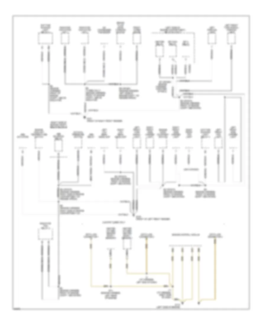
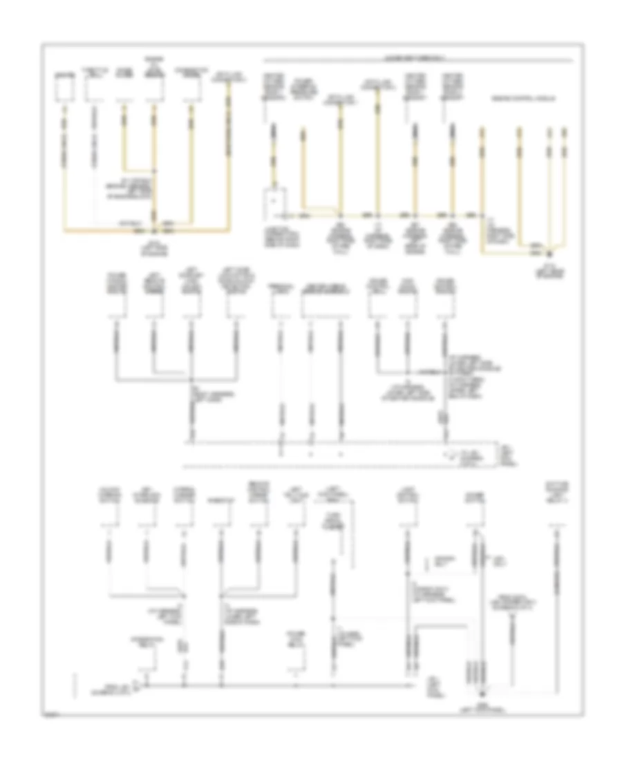
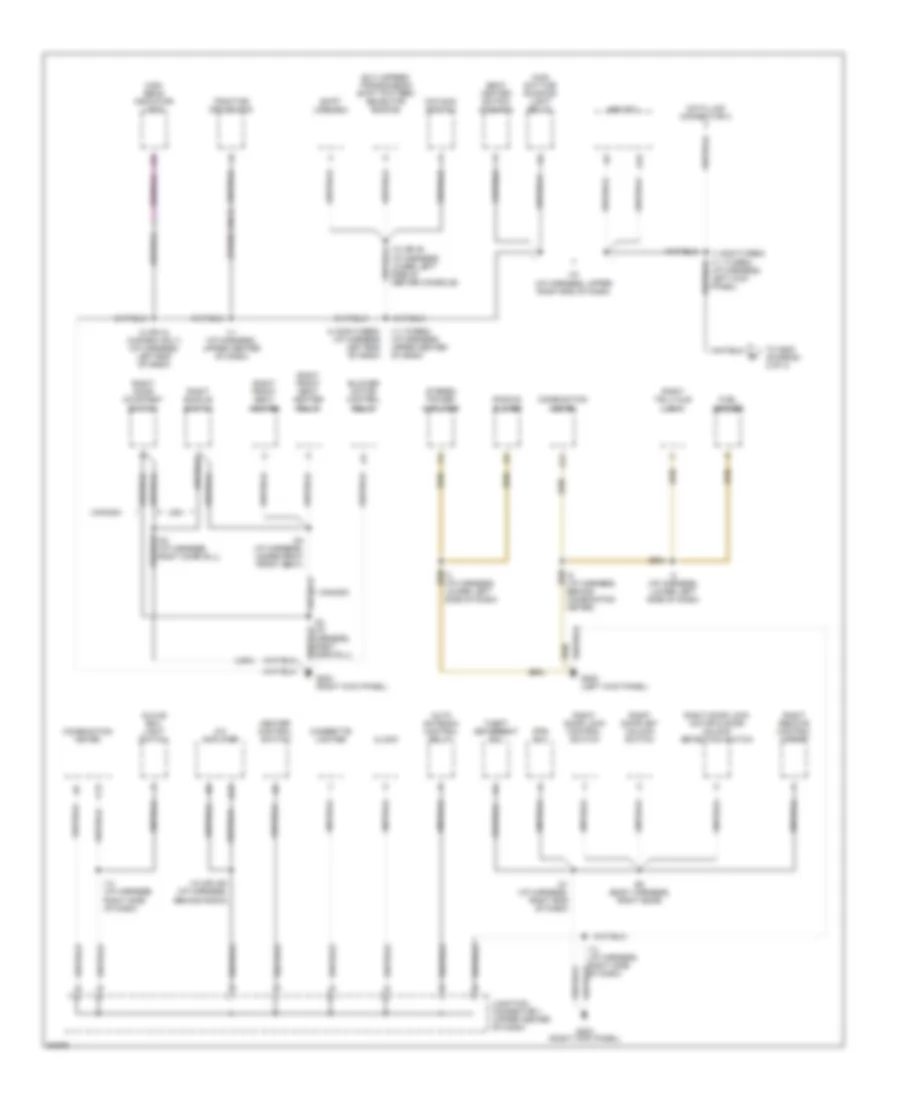
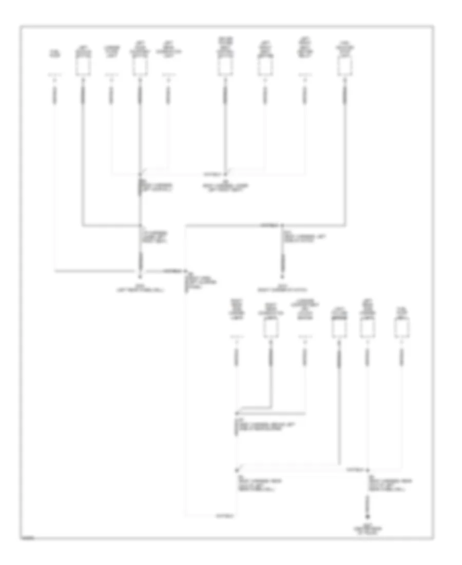
GROUND DISTRIBUTION Ground Distribution Wiring Diagram (1 of 4) for Toyota Supra 1997 List of elements for Ground Distribution Wiring Diagram (1 of 4) for Toyota Supra 1997: 61 (canada) (engine harness, forward of r/b 2) (left side of engine compartment) relay block 2 (non-turbo) (right side of engine compt) relay block 5 (turbo only) (turbo) 2jz-gte turbo only A/c condenser fan motor A/c dual pressure switch A4 (or b1) Abs actuator Abs relay Abs solenoid relay B69 B78 B79 B80 Brake fluid level warning switch Canada usa Data link connector 1 Data link connector 2 Data link connector 3 Daytime running light relay 3 E14 (engine harness, left rear of engine) E2 (engine harness, front of engine compt above rad) E2 (engine harness, front of engine compt, above rad) E2 (engine harness, front of engine compt, above radiator) E2 (or e18) (engine harness, front of engine compt above rad) E2 (turbo only) (engine harness, front of engine compt, above radiator) E5 (engine harness, right side of engine compartment on E5 (or e19) (engine harness, right side of engine compartment on fender apron) E7 (or e20) E9 (or e21) (engine harness, left side of engine compt, on fender apron) Efi 2 relay Efi main relay Engine control module Engine coolant temperature switch Engine hood courtesy switch Front wiper motor G100 (front of left front fender) G101 (front of right front fender) G112 (left side of engine) Heated oxygen heated bank 1 sensor 1 Heated oxygen sensor bank 1 sensor 2 Heater relay I17 (i/p harness, right side of dash) I2 (i/p harness, left end of dash) Left front fog light Left front side marker light Left front turn signal light Left front turn signal/ parking light Left low beam headlamp Left parking light Nca Radiator fan motor n0 2 Radiator fan motor no 1 Radiator fan relay 2 Right front fog light Right front side marker light Right low beam headlamp Ground Distribution Wiring Diagram (2 of 4) for Toyota Supra 1997 List of elements for Ground Distribution Wiring Diagram (2 of 4) for Toyota Supra 1997: 69 (canada) (i/p harness, lower left side of center console) i9 (turbo) i4 (non-turbo) (i/p harness, upper left end of dash) (left kick panel) r/b 4 (non-turbo only) (turbo only) 2jz-ge non-turbo only B1 (body harness, left door) B69 B78 B79 B80 Canada only Center airbag sensor assembly Combination meter Cruise control ecu Cruise control switch D10 Data link connector 1 Data link connector 2 Data link connector 3 Daytime running light relay 3 Dimmer switch E11 (or e24) (engine harness, left side of engine block) E18 E27 (engine harness, left rear of engine) E28 (engine harness, right side of fire wall) Engine control module Engine oil level sensor From data link connector 3 (diagram 3 of 4) From j/b 1 a (diagram 2 of 4) G112 (left side of engine) G114 (left rear of engine) G200 (left kick panel) H13 Heated oxygen sensor bank 1 sensor 1 Heated oxygen sensor bank 1 sensor 2 Heated oxygen sensor bank 2 sensor 1 I1 (i/p harn, left kick panel) I17 (i/p harness, right side of dash) I2 (canada only) (i/p harness, left kick panel) I2 (i/p harness, left kick panel) I3 (i/p harness, lower left side of dash) I9 (i/p harness, lower left side of center console) Igniter Integration relay J/b 1 (left kick panel) Junction connector 2 (behind right side of dash) K12 Key interlock solenoid Kick down switch Left door key lock/ unlock switch Left door lock motor & door unlock/ detection switch Left remote control mirror Left telltale light Light control switch Nca Noise filter Personal light Power main relay Power steering pressure switch Power window master switch Remote control mirror switch Rheostat Throttle ecu To j/b 1 (diagram 2 of 4) Turn signal flasher Unlock warning switch Usa only Wiper & washer switch Ground Distribution Wiring Diagram (3 of 4) for Toyota Supra 1997 List of elements for Ground Distribution Wiring Diagram (3 of 4) for Toyota Supra 1997: 58 (turbo only) (usa) A/c amplifier A11 A15 Abs ecu Auto antenna control relay B13 B2 (body harness, right door) Blower motor control relay C13 Canada Cigarette lighter Clock Combination meter Data link connector 3 Elc 4-speed transmission shift pattern selector switch Fuel sender G200 (left kick panel) G203 (right kick panel) Glove box light switch Heater control switch High beam indicator light I1 (non-turbo) i11 (turbo) (i/p harness, left kick panel) I10 (or i9) (i/p harness, lower left side of center console) I11 (i/p harness, upper center of dash) I11 (turbo) (i/p harness upper center of dash) I14 (i/p harness, right side of dash) I15 (or i25) (i/p harness, behind radio) I18 (i/p harness, upper right end of dash) I2 (or i4) (canada only) (i/p harness, left end of dash) I21 (i/p harness, right end of dash) I23 (i/p harness, right door sill) I24 (i/p harness, under right front seat) I3 (i/p harness, lower left side of dash) I4 (non-turbo) (i/p harness left end of dash) I8 (i/p harness, behind combination meter) Junction connector 1 (upper center of dash) Main daytime running light relay O/d main switch Pps ecu Radio & player Right buckle switch Right door courtesy switch Right door key unlock switch Right door lock control switch Right door lock motor & door unlock detection switch Right front seat heater Right front seat heater relay Right remote control mirror Right telltale light Seat heater switch (canada) Shift lock ecu Stereo power amplifier Theft deterrent ecu To g200 (diagram 2 of 4) Traction off switch Usa Ground Distribution Wiring Diagram (4 of 4) for Toyota Supra 1997 List of elements for Ground Distribution Wiring Diagram (4 of 4) for Toyota Supra 1997: 26 B10 (body harness, left side of hatch) B3 (body harness, left door sill) B4 (body harness, rear half of left rear wheelwell) B5 (body harness, rear half of left rear wheelwell) B6 (body harn, left quarter panel) B7 (body harness, behind left side of rear bumper) B9 (body harness, under left front seat) Driver power seat control switch Fuel pump Fuel pump ecu G402 (left rear wheelwell) G407 (center rear of trunk) G410 (right corner of hatch) High mounted stop light I7 (i/p harness, under left front seat) Left buckle switch Left door courtesy switch Left front seat heater Left front seat heater relay Left rear combination light Left rear side marker light License plate light Light failure sensor Luggage compartment key unlock switch Right rear combination light Right rear side marker light
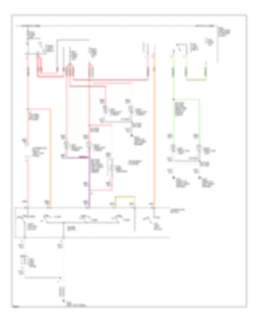
HEADLIGHTS Headlight Wiring Diagram, with DRL for Toyota Supra 1997 List of elements for Headlight Wiring Diagram, with DRL for Toyota Supra 1997: 62 (eng harn, foward of r/b 2) e7 (i/p harn, left end of dash) i4 Anti-theft system Brake fluid level warning switch (on brake fluid reservoir) Combination Daytime running light relay (main) (center of dash) Daytime running light relay 3 (behind right headlight) Dimmer relay (drl 2) Dimmer switch Diode Dome fuse 7.5a Drl fuse 7.5a E2 (eng harn, front of engine compt) E2(gte) e18(ge) E2(gte) e18(ge) (eng harn, frot of engine compt) E9 (gte) e21 (ge) Flash Fog Fog fuse 15a Fog light relay (in r/b 2) Fog light switch G100 (front of left front fender) G100 (front of right front fender) G101 (front of left front fender) G101 (front of right fender) G101 (front of right front fender) G200 (left kick panel) G203 (right kick panel) Gauge fuse 10a H12 Head Head- light relay High High beam indicator Hot at all times Hot in on or start I18 I2 (i/p harn, left end of dash) I2 (or i4) Instrument cluster Integration relay (on j/b 1) J/b 1 (left kick panel) Left fog front light Left headlight hi beam Left headlight lo beam Light control switch Lower left head fuse 15a Lower right head fuse 15a Main fuse 50a Off Parking brake switch R/b 2 (left side of engine compt) R/b 4 (left kick panel) Red Right fog front light Right headlight hi beam Right headlight lo beam Starting/ charging system Switch Tail Upper left head fuse 15a Upper right head fuse 15a Headlight Wiring Diagram, without DRL for Toyota Supra 1997 List of elements for Headlight Wiring Diagram, without DRL for Toyota Supra 1997: 36 Combination switch Dimmer switch E2 (gte) e18 (ge) E2 (gte) e18 (ge) (eng harn, front of engine compt) E9 (gte) e21 (ge) (eng harn, left front fender apron) Flash Fog Fog fuse 15a Fog light relay Fog light switch G100 (front of left front fender) G101 (front of right front fender) G200 (left kick panel) Head Head- light relay High High beam indicator Hot at all times I2 (i/p harn, left end of dash) Instrument cluster Integration relay (left kick panel) J/b 1 (left kick panel) Left front fog light Left head fuse 15a Left headlight hi beam Left headlight lo beam Light control switch Main fuse 50a Off R/b 2 (left side of engine compt) Red Right front fog light Right head fuse 15a Right headlight hi beam Right headlight lo beam Tail
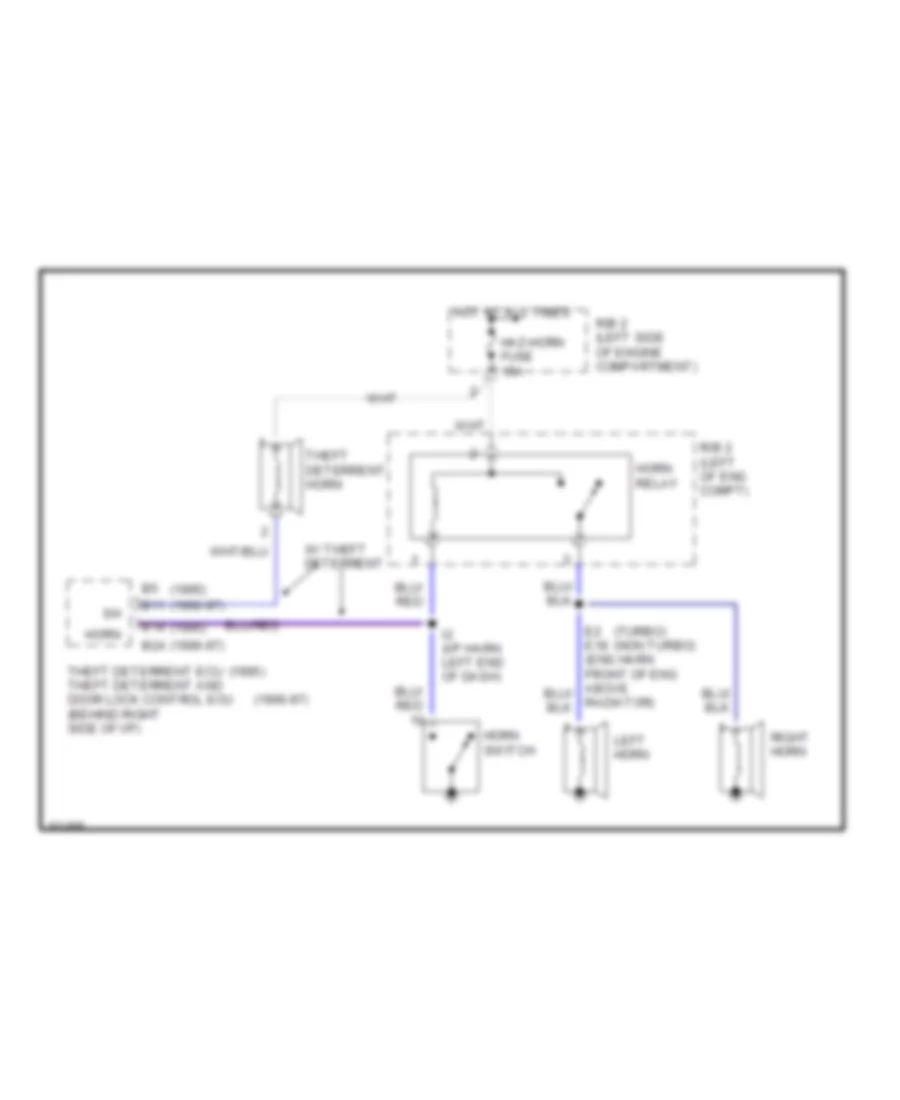
HORN Horn Wiring Diagram for Toyota Supra 1997 List of elements for Horn Wiring Diagram for Toyota Supra 1997: 20 (1995) (1996-97) (turbo) (non turbo) B11 B18 B24 Haz-horn fuse 15a Horn Horn relay Horn switch Hot at all times I2 (i/p harn left end of dash) Left horn R/b 2 (left of eng compt) R/b 2 (left side of engine compartment) Radiator) Right horn Theft deterrent ecu theft deterrent and door lock control ecu (behind right side of i/p) Theft deterrent horn W/ theft deterrent
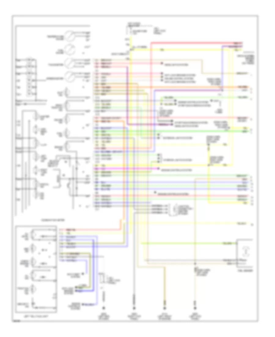
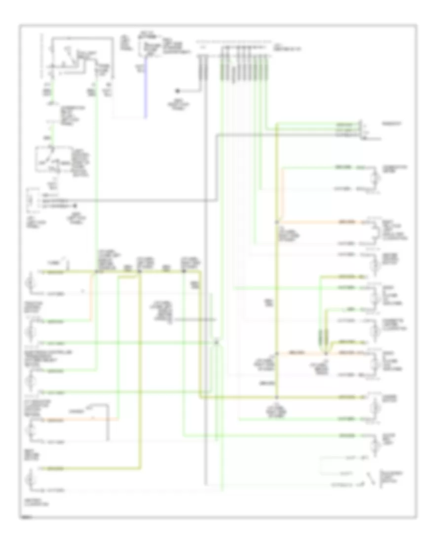
INSTRUMENT CLUSTER Instrument Cluster Wiring Diagram (1 of 2) for Toyota Supra 1997 List of elements for Instrument Cluster Wiring Diagram (1 of 2) for Toyota Supra 1997: 69 (all others) i8 (dash harn, right side of dash) (dash harn, right side of dash) i14 A10 A11 A12 A13 Abs ind Anti-lock brakes system Anti-theft system B10 B11 B12 B13 Brake ind Bulb check relay C10 C11 C12 C13 C14 C15 C16 Check engine ind Combination meter Cruise control system Cruise ind Delay E12 E18 Engine controls system Exterior lights system Fuel gauge Fuel ind Fuel sender G110 (left front of engine) G200 (left kick panel) G202 (left end of dash) G203 (right kick panel) Gauge fuse 10a Headlights system High beam ind Hot in run or start I14 I14 (dash harn, right side of dash) I14 (non-turbo m/t) Illum Interior lights system J/b 1 (left kick panel) Junction connector 1 (center of dash) Left telltale light Left turn ind Manual ind Master ind Non- turbo O/d off ind Oil ind Oil level ind Red Right turn ind Security ind Slip ind Snow traction ind Speedometer Starting/charging system Tachometer Temperature gauge Traction off ind Vehicle speed sensor (turbo) (on trans) Instrument Cluster Wiring Diagram (2 of 2) for Toyota Supra 1997 List of elements for Instrument Cluster Wiring Diagram (2 of 2) for Toyota Supra 1997: 59 (canada) (dash harn, left end of dash) i2 (dash harn, right side of dash) e28 (non-turbo) (turbo) (right kick panel) g203 (turbo) (usa non- turbo) (usa) Air conditioning system Brake fluid level switch (brake fluid reservoir) Brk Canada Charge ind Cig fuse 15a Clock Coolant temperature sender (turbo - right of engine) (non-turbo - left front of cylinder head) Cruise control system Daytime running light relay (canada) (center of dash) Diode (at r/b 4, (left side of dash) Dome fuse 7.5a Door ind E11 E13 E28 Ecu-b fuse 10a Electronic power steering system Engine controls system Engine oil level sensor (left side of oil pan) Exterior lights system (light failure sensor) G100 (front of left front fender) G110 (left front of engine) Hot at all times Hot in on Hot in on and acc I14 (dash harn, right side of dash) I17 (dash harn, right side of dash) I18 (dash harn, upper right Ign fuse 7.5a Integration relay Interior lights system Interior lights system (integration relay) Interior lights system (rheostat) J/b 1 (left kick panel) Junction connector 1 (upper center of dash) Odometer/ tripometer Oil pressure switch (left front of cylinder head) Park/neutral position switch Parking brake switch (at base of brake lever) Pkb Pnk R/b 2 (left side of engine compartment) Rear light ind Red Right telltale light Seat belt ind Srs ind Transmissions system (engine control module) Usa Usa turbo
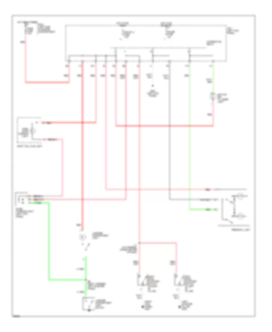
INTERIOR LIGHTS Courtesy Lamps Wiring Diagram for Toyota Supra 1997 List of elements for Courtesy Lamps Wiring Diagram for Toyota Supra 1997: 26 (left quarter pillar) g308 (right kick panel) g203 B6 (body harness, left quarter panel) Diode (interior light) (left kick panel) Dome fuse 7.5a E11 F10 G200 (left kick panel) Gauge fuse 10a Hot at all times Hot in acc or on Hot in on or start I11 (i/p harness, upper center of dash) Ignition key cylinder light Integration relay J/b 1 (left kick panel) Left door courtesy switch (in left "b" pillar) Luggage compartment light Luggage compartment light switch Open door warning light Personal light R/b 2 (left side of engine compartment) Rad no. 2 fuse 7.5a Red Right door courtesy switch (in right "b" pillar) Right telltale light Instrument Illumination Wiring Diagram for Toyota Supra 1997 List of elements for Instrument Illumination Wiring Diagram for Toyota Supra 1997: 42 (i/p harn., left end of dash) i4 (i/p harn., lower left side of center console) i10 (i/p harn., right end of dash) i19 A/t indicator illumination (o/d main switch) A10 Ashtray illumination B12 B13 Canada Cigarette lighter illumination Combination meter E18 Electronic controlled transmission pattern select switch G200 (left kick panel) G203 (right kick panel) Glove box light Glove box light switch Hazard switch Head Heater control switch Hot at all times I12 (i/p harn., behind radio) I14 (i/p harn., right side of dash) Ill- Integration relay (in j/b 1, left kick panel) J/b 1 (left kick panel) J/c 1 (center of i/p) K11 Light control switch (part of combi- nation switch) Off Panel fuse 10a Power fuse 60a R/b 2 (left side of engine compartment) Radio & player (w/ amplifier) Radio & player (w/o amplifier) Rheostat Right telltale light (odo & trip illumination) Seat heater switch Tail Taillight relay Traction control switch Turbo
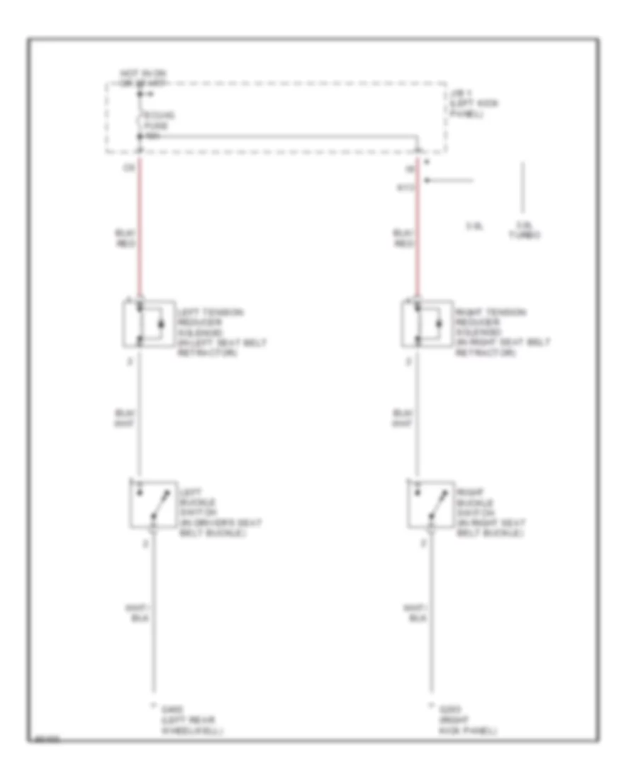
PASSIVE RESTRAINTS Passive Restraint Wiring Diagram for Toyota Supra 1997 List of elements for Passive Restraint Wiring Diagram for Toyota Supra 1997: 12 3.0l 3.0l turbo Ecu-ig fuse 10a G203 (right kick panel) G402 (left rear wheelwell) Hot in on or start J/b 1 (left kick panel) K13 Left buckle switch (in driver's seat belt buckle) Left tension reducer solenoid (in left seat belt retractor) Right buckle switch (in right seat belt buckle) Right tension reducer solenoid (in right seat belt retractor)
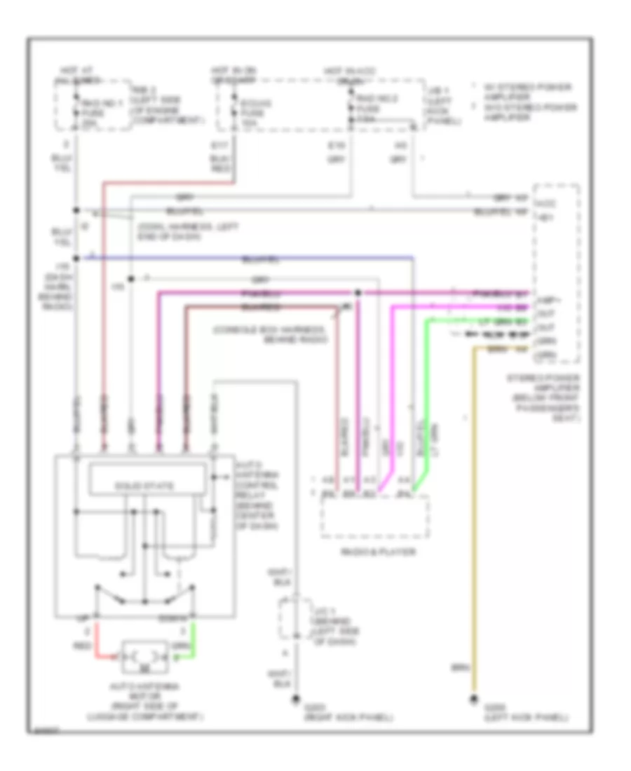
POWER ANTENNA Power Antenna Wiring Diagram for Toyota Supra 1997 List of elements for Power Antenna Wiring Diagram for Toyota Supra 1997: 32 (console box harness, behind radio (cowl harness, left end of dash) +b1 Acc Amp+ Auto antenna control relay (behind center of dash) Auto antenna motor (right side of luggage compartment) B10 Down E10 E17 Ecu-ig fuse 10a G200 (left kick panel) G203 (right kick panel) Hot at all times Hot in acc or on Hot in on or start I15 I15 (dash harn, behind radio) I16 J/b 1 (left kick panel) J/c 1 (behind left side of dash) Nca Out R/b 2 (left side of engine compartment) Rad no.1 fuse 20a Rad no.2 fuse 7.5a Radio & player Red Solid state Stereo power amplifier (below front passenger's seat) W/ stereo power amplifier w/o stereo power amplifier
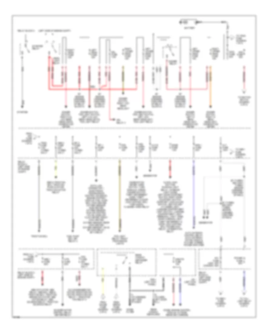
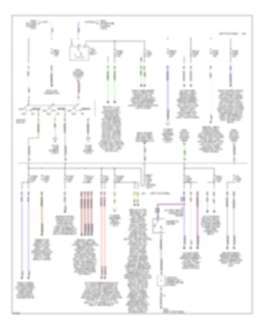
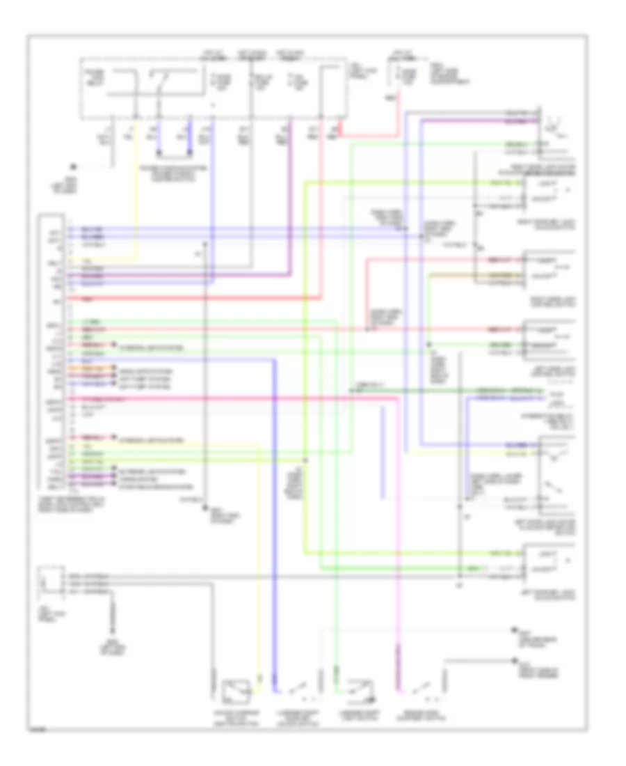
POWER DISTRIBUTION Power Distribution Wiring Diagram (1 of 2) for Toyota Supra 1997 List of elements for Power Distribution Wiring Diagram (1 of 2) for Toyota Supra 1997: 76 (can) (left side of engine compt) (usa) (usa) (canada) A/c condenser fan motor, radiator fan motor, radiator fan relay 1, radiator fan relay 2 Abs & traction ecu, traction pump & motor, traction motor relay Abs 1 fuse 60a Abs 2 fuse 30a (turbo only) Abs actuator, abs relay, abs ecu, abs & traction ecu, traction brake actuator, abs motor relay, abs solenoid relay, traction solenoid relay Alt fuse 120a Alt-s fuse 7.5a Am1 fuse 50a 60a Am2 fuse 30a Auto antenna control relay, auto antenna motor, radio & player, stereo power amplifier Battery Blower motor control relay, heater relay Clock, main daytime running light relay, interior light diode, left door courtesy switch, right door courtesy switch, door key lock/unlock switch, ignition key cylinder light, luggage compartment light switch, luggage compartment light, personal light, open door warning light, theft deterrent & door lock control ecu, power main relay, integration relay Combination meter, horn switch, turn signals, horns, hazard switch, theft deterrent horn, theft deterrent & door lock control ecu, turn signal flasher, horn relay Data link connector 1, electronic transmission control solenoid, engine control module, fuel pump ecu, main heated oxygen sensor, sub heated oxygen sensor, idle air control valve, mass air flow meter, front main heated oxygen sensor, rear main heated oxygen sensor, vsv's, efi main relay, efi 2 relay Dimmer relay Dimmer switch, fog light switch, left hi & low beam headlights, fog light relay Dimmer switch, fog light switch, left low beam headlight, fog light relay Dimmer switch, left hi beam headlight, combination meter Dimmer switch, right hi & low beam headlights, combination meter Dimmer switch, right hi beam headlight, combination meter Dimmer switch, right low beam headlight Diode, engine control module, outside rearview mirrors Dome fuse 7.5a Drl fuse 7.5a Drl relay 3 E20 (non- turbo) (engine harness, forward of r/b 2) E7 (engine harness, forward of relay block 2) E7 (turbo) e20 (non- turbo) (engine harness, forward of r/b 2) Efi 1 fuse 30a Efi 2 fuse 30a (turbo only) Fan fuse 30a (turbo only) Fog fuse 15a Fog light relay, front fog/parking lights From alt c fuse (diagram 1 of 2) From am2 fuse (diagram 1 of 2) From defog fuse (diagram 2 of 2) From gauge fuse (diagram 2 of 2) Fuel pump ecu, efi relay 2 Generator Haz- horn fuse 15a Head- light relay Htr fuse 50a I4 (i/p harness, left end of dash) I6 (i/p harn, left door sill) J/b 1 (left kick panel) Left head fuse 15a Left lower head fuse 15a Left upper head fuse 15a Main fuse 50a Mir-htr fuse 10a Noise filter Power fuse 60a R/b 4 (left kick panel) Rad 1 fuse 20a Rear window defog grid Rear window defogger relay Red Relay block 2 Relay block 2 (left side of engine compt) Right head fuse 15a Right lower head fuse 15a Right upper head fuse 15a Starter Starter relay To abs 1 fuse (diagram 1 of 2) To ignition switch (diagram 2 of 2) To obd-ii fuse (diagram 2 of 2) To tail- light relay (diagram 2 of 2) To trac fuse (diagram 1 of 2) Trac fuse 7.5a (turbo only) Traction ecu Power Distribution Wiring Diagram (2 of 2) for Toyota Supra 1997 List of elements for Power Distribution Wiring Diagram (2 of 2) for Toyota Supra 1997: 65 (diagram 1 of 2) (left kick panel) A/c amplifier, abs ecu, abs & traction ecu, center airbag sensor assembly, cruise control ecu, main daytime running light relay, data link connector 1, right telltail light, traction ecu A/c amplifier, center airbag sensor assembly, clock, shift lock ecu, theft deterrent & door lock ecu A/c triple pressure switch, a/c amplifier, a/c magnetic clutch & lock sensor, air inlet control servo motor, engine coolant temperature switch, engine control module, heater control switch, radiator fan relay 1, radiator fan relay 2, a/c magnetic clutch relay, heater relay Abs actuator, abs relay, a/c amplifier, abs ecu, abs & traction ecu, brake fluid level warning switch, back- up light switch, combination meter, cruise control clutch switch, cruise control ecu, data link connector 1 & 2, main daytime running light relay, engine coolant temp sender, engine oil level sensor, engine control module, fuel pump & sender, generator, light failure sensor, o/d main switch, oil pressure switch, parking brake switch, park/neutral position switch, back-up lights, traction brake actuator, telltale lights, traction ecu, vehicle speed sensor 1, diode, integration relay, rear window degogger relay, abs solenoid relay, traction motor relay, traction solenoid relay Abs ecu, abs & traction ecu, abs lateral acceleration sensor, auto antenna control relay, buckle switches, cruise control ecu, pps ecu, shift lock ecu, theft deterrent & door lock control ecu, traction ecu, tension reducer solenoids, power main relay Abs ecu, abs & traction ecu, cruise control ecu, engine control module, high mounted stop light, light failure sensor, stop light switch, shift lock ecu, rear combination lights, traction ecu Acc Ashtray illum, idle-up diode, electronically controlled transmission pattern select switch, engine control module, glove box light, glove box light switch, hazard switch, heater control switch, o/d main switch, rheostat, radio & player, seat heater switch, right tell- tale light, trac off switch Auto antenna control relay, radio & player, outside mirrors, stereo power amplifier, integration relay C14 C16 Center airbag sensor assembly, engine control module, generator, right telltale light Cig fuse 15a Cigarette lighter Combination meter, turn signal switch, front turn signal lights, rear combination lights, hazard switch, turn signal flasher Data link connector 3 Defog fuse 30a Door fuse 30a E10 E12 E17 Ecu-b fuse 10a Ecu-ig fuse 10a Engine control module, clutch start switch, park/neutral position switch, theft deterrent & door lock control ecu, starter relay From am1 fuse d From am2 fuse (diagram 1 of 2) From ignition switch (diagram 2 of 2) From power fuse (diagram 1 of 2) Front & rear wiper/washer switches, front wiper motor, rear wiper motor & relay, washer motor Front side marker lights, front fog/ parking lights, license plate light, light failure sensor, rear side marker lights, rear combination lights, diode G10 G203 (right kick panel) Gauge fuse 10a H12 H15 H16 Htr fuse 7.5a I10 I14 I8 (i/p harn, behind combination meter) Ign fuse 7.5a Ignition switch J/b 1 Junction connector 1 (upper center of dash) K13 Obd-ii fuse 7.5a Off Panel fuse 10a Rad 2 fuse 7.5a Right power window control switch, left power window & door lock master control switch, left power window motor, right power window motor, power seat control switch, power seat motor, theft deterrent & door lock control ecu, power main relay Seat heater switch, seat heaters, seat heater relays Seat- htr fuse 15a (canada only) Start Start fuse 7.5a Stop fuse 15a Tail fuse 10a Tail- light relay To cig fuse (diagram 2 of 2) To ign fuse (diagram 2 of 2) To rear defogger relay (diagram 1 of 2) To rear window defogger relay (diagram 2 of 2) Turn fuse 7.5a Wiper fuse 20a
POWER DOOR LOCKS Power Door Lock Wiring Diagram for Toyota Supra 1997 List of elements for Power Door Lock Wiring Diagram for Toyota Supra 1997: 71 (1996 only) (1996 only) i21 (dash harn, lower left side of dash) (1996 only) i3 (dash harn, right end of dash) i21 +b1 +b2 Acc Act+ Act- Anti-theft system Cig fuse 15a D10 Dome fuse 7.5a Door fuse 30a Dswd Dswh Dswl Dswp E11 E17 Ecu-ig fuse 10a Engine hood courtesy switch Exterior lights system G101 (front side of front fender) G201 (right end of dash) G202 (left end of dash) G407 (center rear of trunk) H15 Head Headlights system Horn Horns system Hot at all times Hot in acc or run Hot in run or start I21 I21 (dash harn, right end of dash) Ind Integration relay (1996 only) (on j/b 1) Interior lights system J/b 1 (left kick panel) K12 Ksw Left door key lock/ unlock switch Left door lock control switch Left door lock motor & unlock detection switch Lock Lswd Lswp Lug Luggage compt door key unlock switch Luggage compt light switch Plck Power main relay Power windows system (power window master switch) Prly R/b 2 (left side of engine compartment) Red Right door key lock/ unlock switch Right door lock control switch Right door lock motor & unlock detection switch Srly Starting/charging system T13 Tail Theft deterrent ecu & door lock control ecu (right side of dash) Ul1 Ul2 Ul3 Unlock Unlock warning switch (ignition switch)
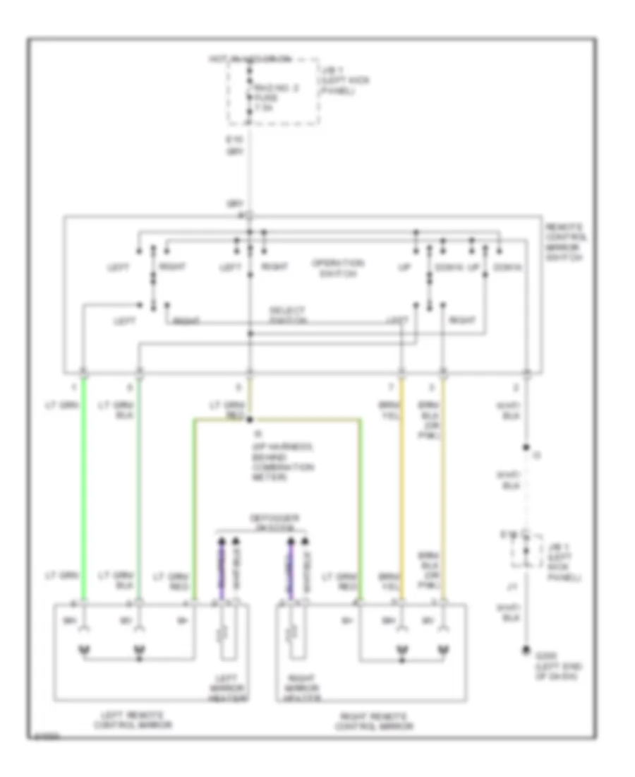
POWER MIRRORS Power Mirror Wiring Diagram for Toyota Supra 1997 List of elements for Power Mirror Wiring Diagram for Toyota Supra 1997: 18 (i/p harness, behind combination meter) Defogger system Down E10 E18 G200 (left end of dash) Hot in acc or on J/b 1 (left kick panel) Left Left mirror heater Left remote control mirror Operation switch Rad no. 2 fuse 7.5a Remote control mirror switch Right Right mirror heater Right remote control mirror Select switch
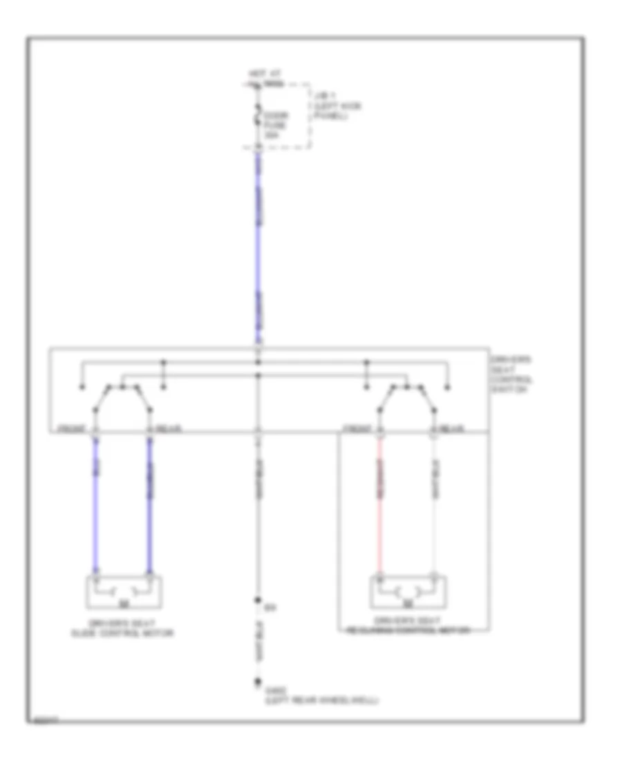
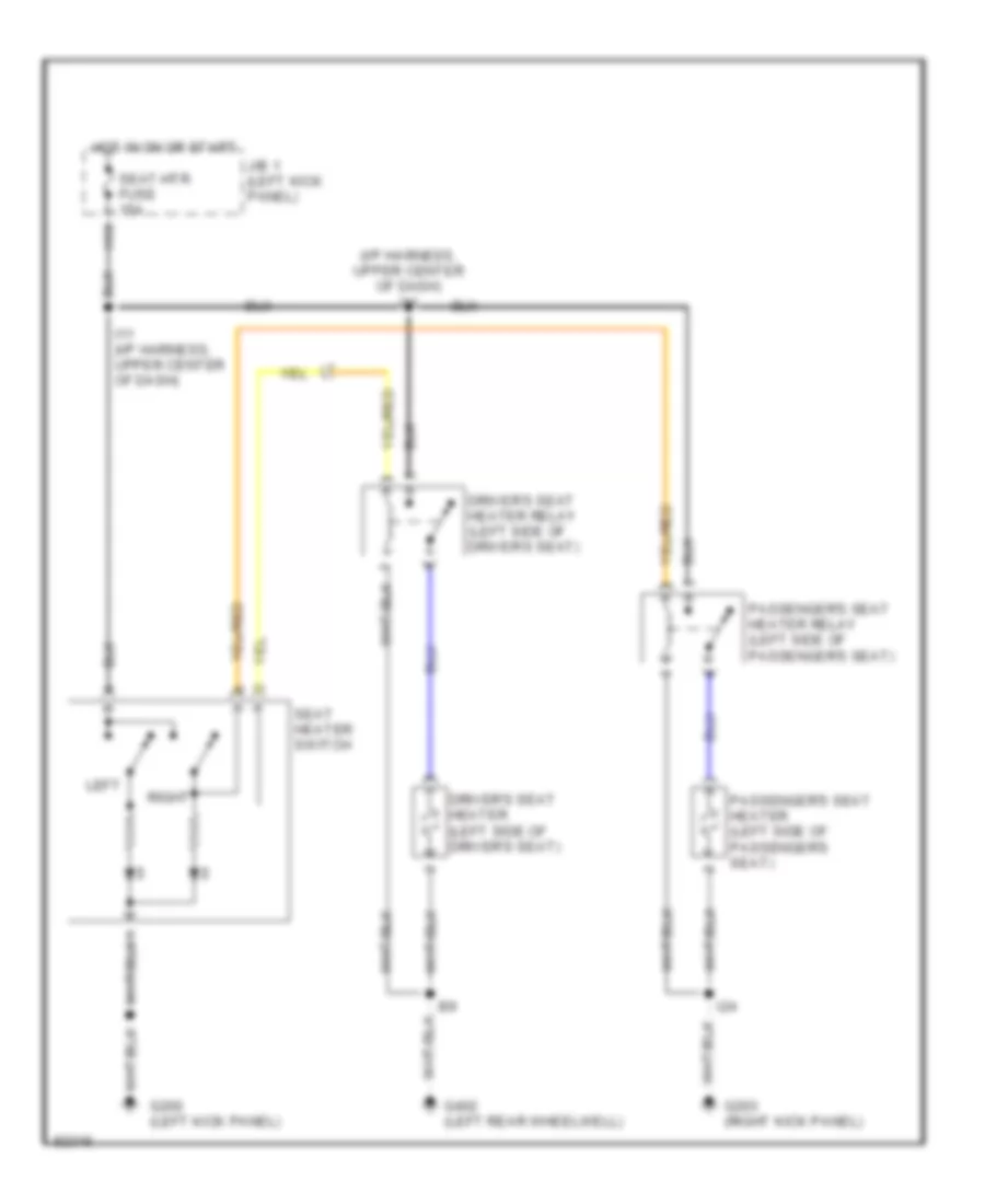
POWER SEATS Driver Power Seat Wiring Diagram for Toyota Supra 1997 List of elements for Driver Power Seat Wiring Diagram for Toyota Supra 1997: 10 Door fuse 30a Driver's seat control switch Driver's seat reclining control motor Driver's seat slide control motor Front G402 (left rear wheelwell) H15 Hot at all times J/b 1 (left kick panel) Rear Heated Seats Wiring Diagram, Canada for Toyota Supra 1997 List of elements for Heated Seats Wiring Diagram, Canada for Toyota Supra 1997: 17 (i/p harness, upper center of dash) i11 Driver's seat heater (left side of driver's seat) Driver's seat heater relay (left side of driver's seat) G200 (left kick panel) G203 (right kick panel) G402 (left rear wheelwell) H16 Hot in on or start I11 (i/p harness, upper center of dash) I24 J/b 1 (left kick panel) Left Passenger's seat heater (left side of passenger's seat) Passenger's seat heater relay (left side of passenger's seat) Right Seat heater switch Seat-htr fuse 15a
POWER WINDOWS Power Window Wiring Diagram for Toyota Supra 1997 List of elements for Power Window Wiring Diagram for Toyota Supra 1997: 37 Auto B19 D10 Dome fuse 7.5a Door fuse 30a Down Driver's E11 E17 Ecu-ig fuse 10a G201 (right end of dash) G202 (left end of dash) G203 (right kick panel) G402 (left rear wheelwell) H15 Hot at all times Hot in on or start I21 I23 J/b 1 (on left kick panel) J/b 1 (on left kick panel) Key off power circuit Left door courtesy switch Left power window motor Lock Normal Passenger's Power fuse 60a Power main relay Power window master switch R/b 2 (on left side of engine compartment) Red Right door courtesy switch Right power window control switch Right power window motor Solid state Theft deterrent & door lock control ecu (behind right side of dash)
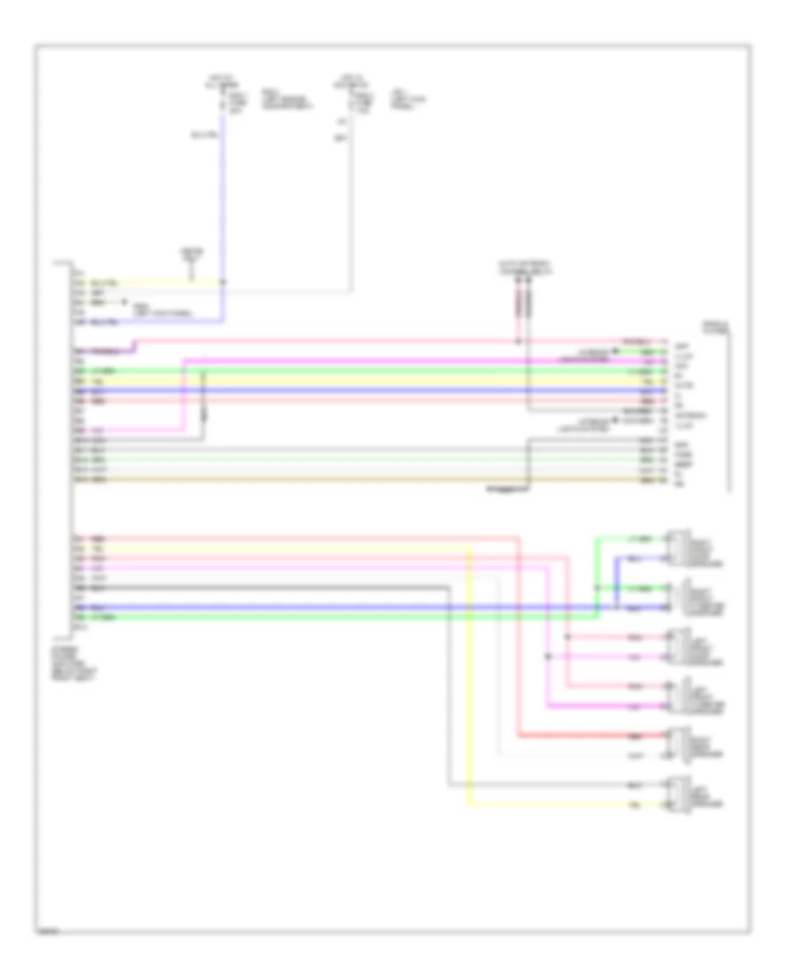
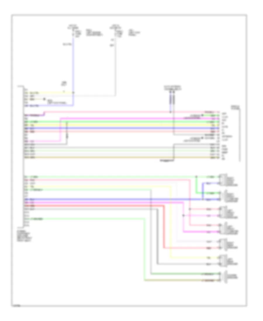
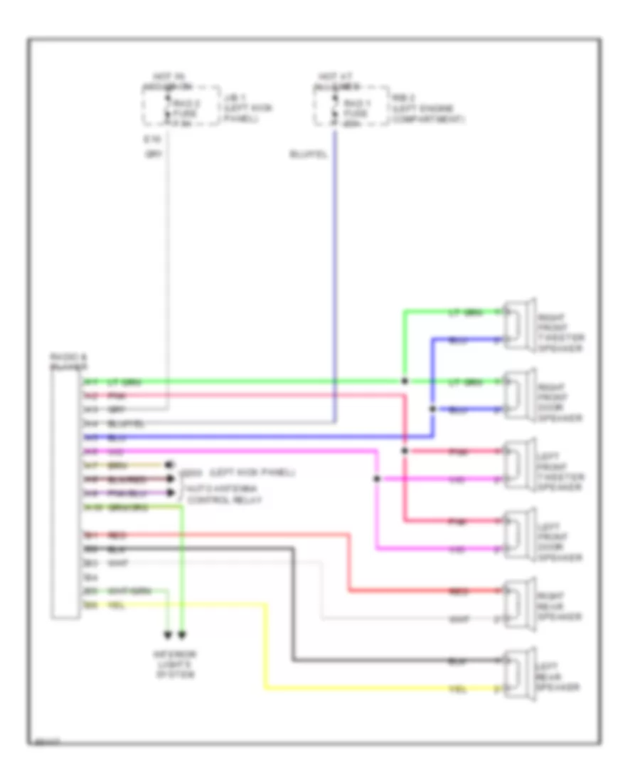
RADIO Radio Wiring Diagrams, with Amplifier for Toyota Supra 1997 List of elements for Radio Wiring Diagrams, with Amplifier for Toyota Supra 1997: 40 1993-96 only Acc Acc or on All times Amp Antenna Auto antenna B10 B11 B12 B13 B14 Beep C4 b4 C5 b5 Control relay D10 Fade G200 (left kick panel) Gnd Hot at Hot in Illum Interior lights system J/b 1 (left kick panel) Left front door speaker Left front tweeter speaker Left rear speaker Mute Nca Pnk R/b 2 (left engine compartment) Rad 1 fuse 20a Rad 2 fuse 7.5a Radio & player Red Right front door speaker Right front tweeter speaker Right rear speaker Stereo power amplifier (below right front seat) Radio Wiring Diagrams, with Amplifier & Woofer for Toyota Supra 1997 List of elements for Radio Wiring Diagrams, with Amplifier & Woofer for Toyota Supra 1997: 47 Acc Acc or on All times Amp Antenna Auto antenna B10 B11 B12 B13 B14 Beep C10 C11 C12 C13 C14 C15 C16 C4 b4 C5 b5 Control relay Fade G200 (left kick panel) Gnd Hot at Hot in Illum Interior lights system J/b 1 (left kick panel) Left front door speaker Left front tweeter speaker Left rear speaker Mute Nca Only Pnk R/b 2 (left engine compartment) Rad 1 fuse 20a Rad 2 fuse 7.5a Radio & player Red Right front door speaker Right front tweeter speaker Right rear speaker Stereo component amplifier (below right front seat) Woofer speaker Radio Wiring Diagrams, without Amplifier for Toyota Supra 1997 List of elements for Radio Wiring Diagrams, without Amplifier for Toyota Supra 1997: 24 (left kick panel) A10 Acc or on All times Auto antenna Control relay E10 G200 Hot at Hot in Interior lights system J/b 1 (left kick panel) Left front door speaker Left front tweeter speaker Left rear speaker Pnk R/b 2 (left engine compartment) Rad 1 fuse 20a Rad 2 fuse 7.5a Radio & player Red Right front door speaker Right front tweeter speaker Right rear speaker
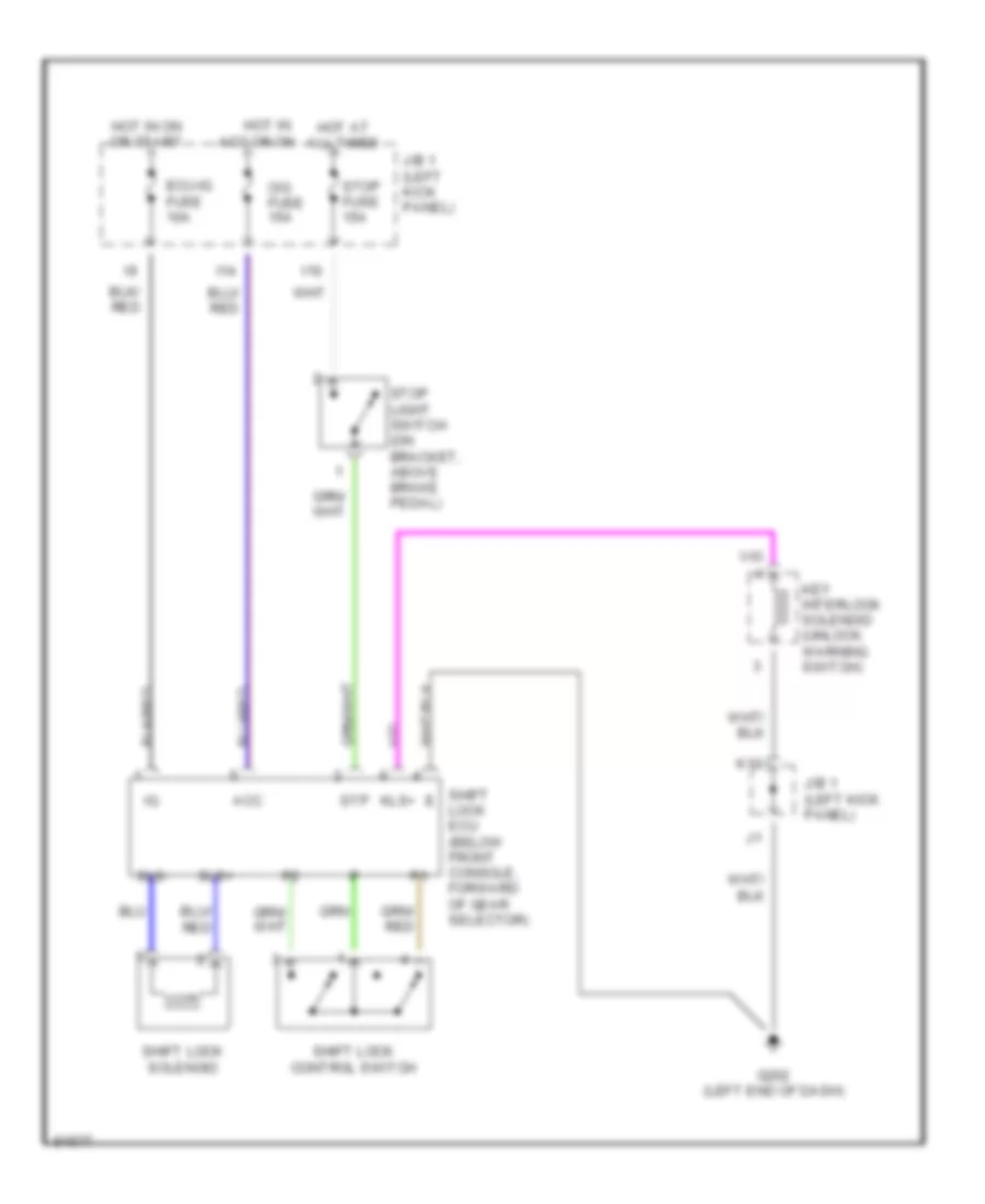
SHIFT INTERLOCKS Shift Interlock Wiring Diagram for Toyota Supra 1997 List of elements for Shift Interlock Wiring Diagram for Toyota Supra 1997: 22 Acc Cig fuse 15a Ecu-ig fuse 10a G202 (left end of dash) Hot at all times Hot in acc or on Hot in on or start I10 I14 J/b 1 (left kick panel) J/b 1 (left kick panel) K12 Key interlock solenoid (unlock warning switch) Kls+ Shift lock control switch Shift lock ecu (below front console, forward of gear selector) Shift lock solenoid Sls+ Sls- Stop fuse 15a Stop light switch (on bracket, above brake pedal) Stp
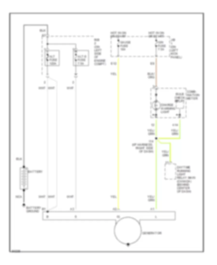
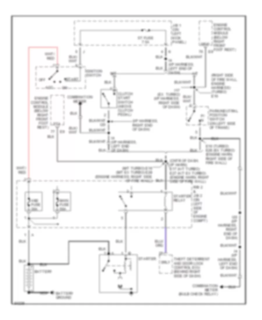
STARTING/CHARGING Charging Wiring Diagram for Toyota Supra 1997 List of elements for Charging Wiring Diagram for Toyota Supra 1997: 18 A14 Alt fuse 120a Alt-s fuse 7.5a Battery Battery ground Bulb check relay Charge warning light Comb- ination meter Daytime running light relay main (canada) (behind center of dash) E12 Gauge fuse 10a Generator Hot in on or start I14 (i/p harness, right side of dash) Ign fuse 7.5a J/b (on left kick panel) Nca R/b (on left side of engine compt) Starting Wiring Diagram for Toyota Supra 1997 List of elements for Starting Wiring Diagram for Toyota Supra 1997: 35 (cntr of dash, i/p harn) e17 (a/t turbo) e27 (a/t ex turbo) (engine harn, right side of fire wall) (i/p harness, right end of dash) (m/t turbo) e16 (m/t ex turbo) e28 (engine harness, right side of fire wall) (right side of fire wall, engine harness) (turbo) e16 A/t Acc Am2 fuse 30a Battery Battery ground Clutch start switch (above clutch pedal) Combination meter Combination meter (bulb check relay) E16 (turbo) e28 (ex turbo) (engine harn, right side of fire wall) Engine control module (below right front foot rest) I17 (ex turbo) (i/p harness, right side of dash) I20 I20 (i/p harness, right end of dash) I4 (i/p harness, left end of dash) Ignition switch J/b 1 (on left kick panel) M/t Main fuse 50a Nca Nsw Off P/ n Park/neutral position switch (on left side of trans) R/b 2 & j/b 2 (on left side of engine compt) Srly St fuse 7.5a Sta Start Starter Starter relay Theft deterrent and door lock control ecu (behind right side of dash)
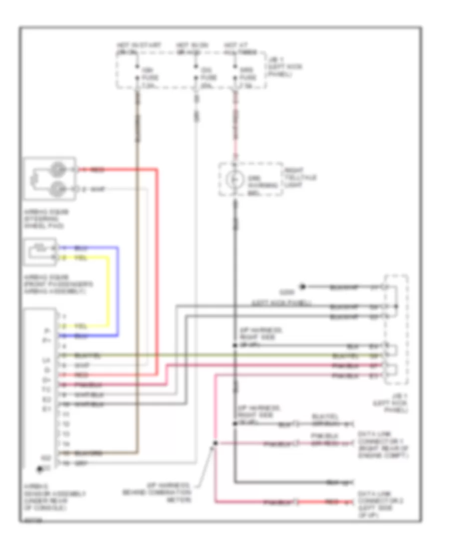
SUPPLEMENTAL RESTRAINTS Supplemental Restraint Wiring Diagram for Toyota Supra 1997 List of elements for Supplemental Restraint Wiring Diagram for Toyota Supra 1997: 23 (i/p harness, behind combination meter) (i/p harness, right side of i/p) (left kick panel) Acc Airbag sensor assembly (under rear of console) Airbag squib (front passenger's airbag assembly) Airbag squib (steering wheel pad) Cig fuse 15a Data link connector 1 (right rear of engine compt) Data link connector 2 (left side of i/p) E13 G10 G200 Hot at all times Hot in on or acc Hot in start or on Ig2 Ign fuse 7.5a J/b 1 (left kick panel) Red Right telltale light Srs fuse 7.5a Srs warning ind
TRANSMISSION
3.0L 3.0L Non-Turbo, A/T Wiring Diagram for Toyota Supra 1997 List of elements for 3.0L Non-Turbo, A/T Wiring Diagram for Toyota Supra 1997: 87 (dash harn, right end of dash) i21 (dash harn, right side of dash) (dash harn, right side of dash) i17 (engine harn, left rear of engine) (engine harn, right side of firewall) (engine harn, upper front of engine) e23 (left kick panel) (under gas pedal) A/t fluid temperature sensor (on trans) B6 (body harn, left quarter panel) Batt Cruise control ecu (behind left side of dash) E10 E12 E20 E25 (engine harness, left side of engine compt) E26 E28 E28 (engine harn, right side of firewall) Efi fuse 30a Efi main relay Electronic controlled trans- mission pattern select switch Electronic controlled transmission solenoid Engine control module (below right front footrest) Engine coolant temperature sensor (left front of cyl head) Eo1 Eo2 Eo3 Exterior lights system G100 (front of left front fender) G114 (intake manifold) G200 Gauge fuse 10a H13 Hot at all times Hot in on or start Hot in start I10 I17 I4 (dash harn, left end of dash) Idl1 Ign fuse 7.5a Igsw Instrument cluster system Interior lights system J/b 1 (left kick panel) Kick down switch M-rel Mass air flow sensor (behind air filter housing) No. 1 No. 2 No. 3 Nsw O/d main switch Od1 Od2 Oil Park/neutral position switch (left side of transmission) Pin 6 Pin c10 Pin c11 Pin c12 Pin c2 Pin c4 Pin c6 Pin c7 Pin c8 Pnk R/b 2 (left engine compt) Red Sp1 Sp2+ Sp2- St fuse 7.5a Sta Starting/ charging system Stop fuse 15a Stop light switch (brake pedal bracket) Stp Te1 Te1 data link connector 1 (right side of firewall) Tha Throttle position sensor (on throttle body) Thw Vcc Vehicle speed sensor (for e.c.t.) (rear of trans tailshaft) Vta1 3.0L Turbo, A/T Wiring Diagram for Toyota Supra 1997 List of elements for 3.0L Turbo, A/T Wiring Diagram for Toyota Supra 1997: 97 (below left dash) data link connector 2 (dash harn, right end of dash) (dash harn, upper center of dash) (engine harn, behind center of dash) (engine harn, left side of engine compt) (engine harness, right side of firewall) (left kick panel) (on throttle body) (right rear eng compt) data link connector 1 (under gas pedal) A/t fluid temperature sensor (on trans) Batt Cruise control ecu (behind left center of dash) E10 E12 E13 E14 E16 E17 Ect Efi fuse 30a Efi main relay Electronic controlled transmission pattern select switch Electronic controlled transmission solenoid Engine control module (below right front footrest) Engine coolant temperature sensor (right front of cyl head) Eo1 Eo2 Eo3 G100 (front of left front fender) G114 (intake manifold) G200 Gauge fuse 10a H13 Hot at all times Hot in on or start Hot in start I10 I11 I17 I21 Idl1 Idl2 Ign fuse 7.5a Igsw Instru- ment cluster system Interior lights system J/b 1 Kick down switch M-rel Nco+ Nco- No. 1 No. 2 Nsw O/d direct clutch speed sensor (side of transmission) O/d main switch Od1 Od2 Oil Park/neutral position switch (left side of transmission) Pin 6 Pin c10 Pin c11 Pin c12 Pin c2 Pin c4 Pin c6 Pin c7 Pin c8 Pnk R/b 2 (left engine compt) Red Sln Sln- Slt Slt+ Slt- Slu Slu- Sp1 Sp2+ Sp2- St fuse 7.5a Sta Starting/ charging system Stop fuse 15a Stop light switch (brake pedal bracket) Stp Sub-throttle position sensor Te1 Throttle position sensor Thw Vcc Vehicle speed sensor (for e.c.t.) (rear of trans tailshaft) Vta1 Vta2
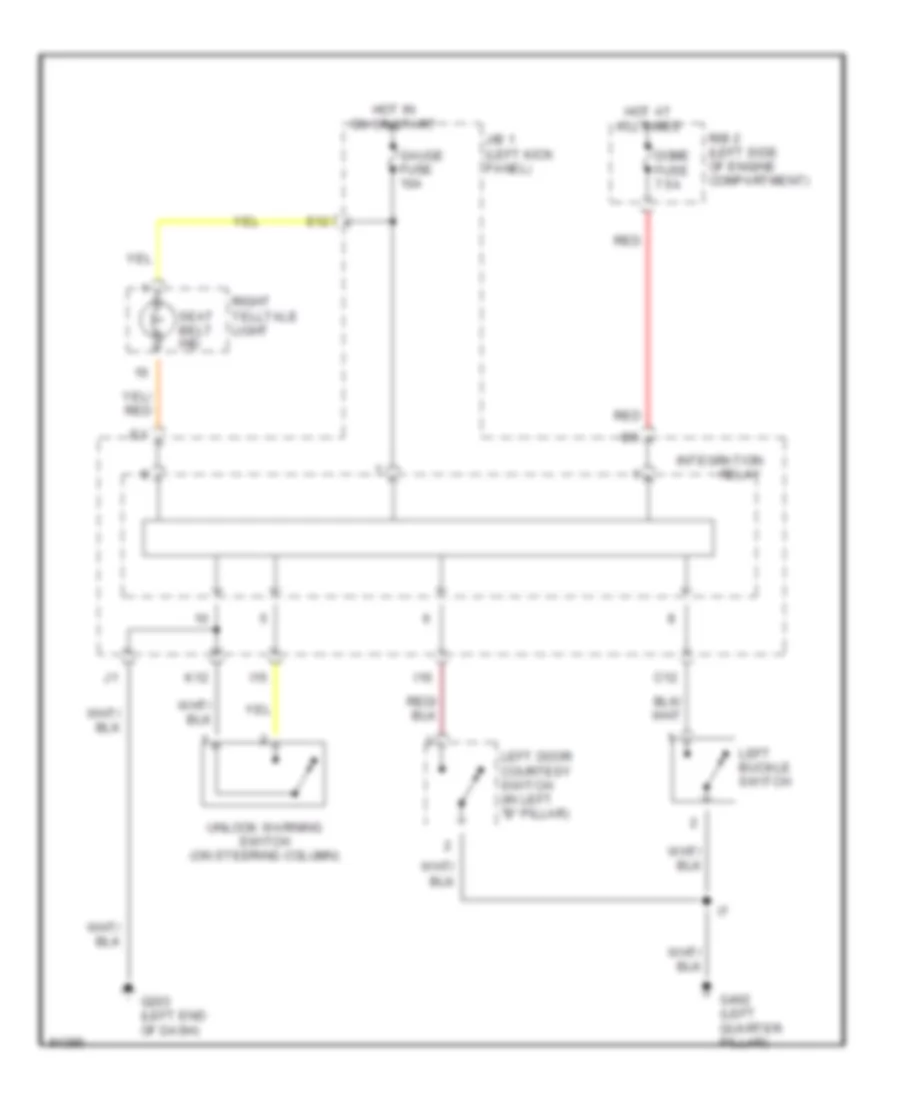
WARNING SYSTEMS Warning System Wiring Diagrams for Toyota Supra 1997 List of elements for Warning System Wiring Diagrams for Toyota Supra 1997: 21 C12 Dome fuse 7.5a E12 G203 (left end of dash) G402 (left quarter pillar) Gauge fuse 10a Hot at all times Hot in on or start I15 I16 Integration J/b 1 (left kick panel) K12 Left buckle switch Left door courtesy switch (in left "b" pillar) R/b 2 (left side of engine compartment) Red Relay Right telltale light Seat belt ind Unlock warning switch (on steering column)
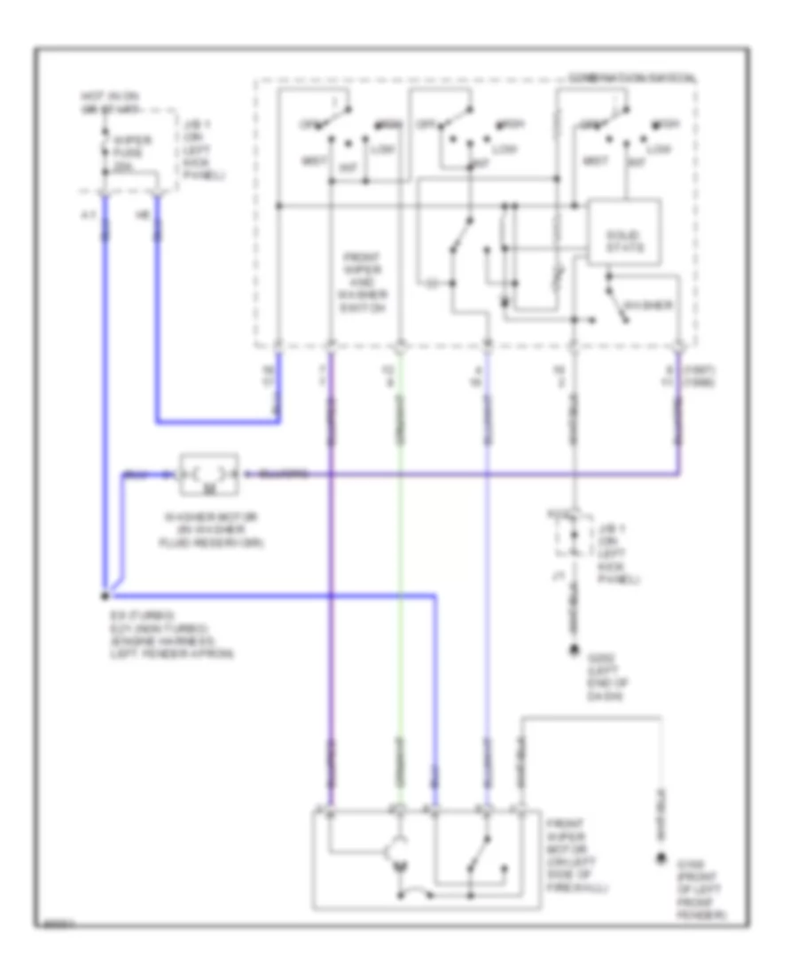
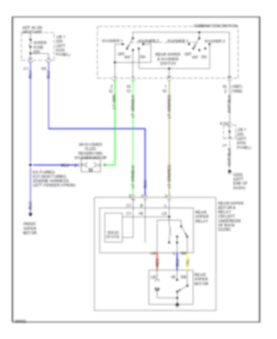
WIPER/WASHER Front Wiper/Washer Wiring Diagram for Toyota Supra 1997 List of elements for Front Wiper/Washer Wiring Diagram for Toyota Supra 1997: 19 (1997) (1998) Combination switch E9 (turbo) e21 (non turbo) (engine harness, left fender apron) Front wiper and washer switch Front wiper motor (on left side of firewall) G100 (front of left front fender) G202 (left end of dash) High Hot in on or start Int J/b 1 (on left kick panel) K12 Low Mist Off Solid state Washer Washer motor (in washer fluid reservoir) Wiper fuse 20a Rear Wiper/Washer Wiring Diagram for Toyota Supra 1997 List of elements for Rear Wiper/Washer Wiring Diagram for Toyota Supra 1997: 21 (1997) (1998) (in washer fluid reservoir) washer motor Combination switch E9 (turbo) e21 (non turbo) (engine harness, left fender apron) Front wiper motor G202 (left end of dash) Hot in on or start Int J/b 1 (on left kick panel) K12 Off On int Rear wiper & washer switch Rear wiper motor Rear wiper motor & relay (on left underside of back door) Rear wiper relay Red Solid state Washer 1 Washer 2 Wiper fuse 20a