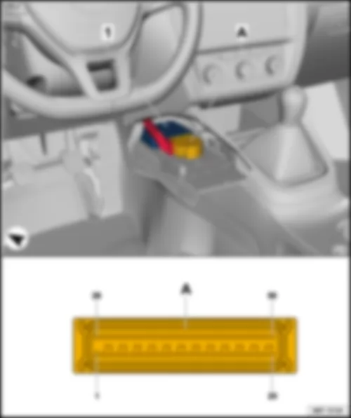
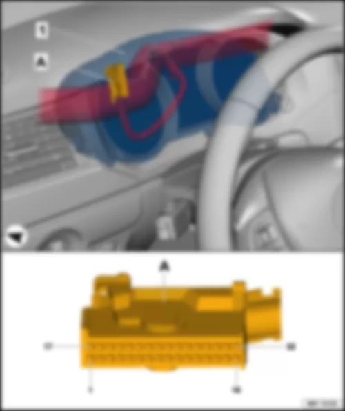
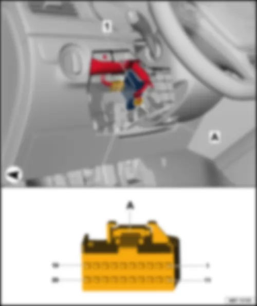
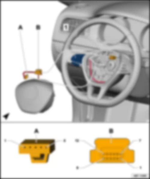
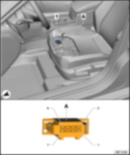
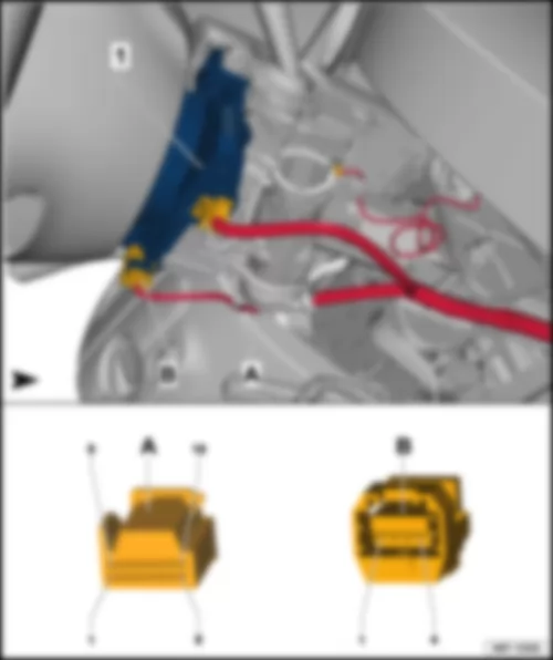
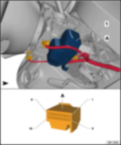
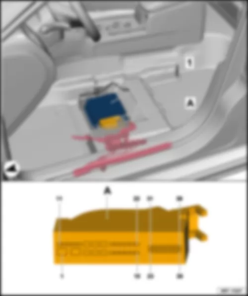
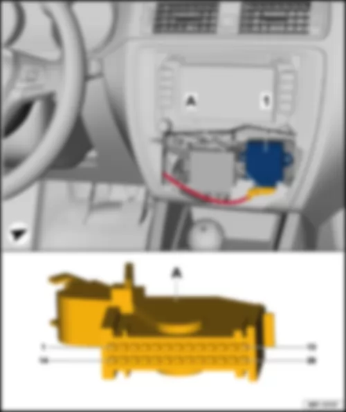
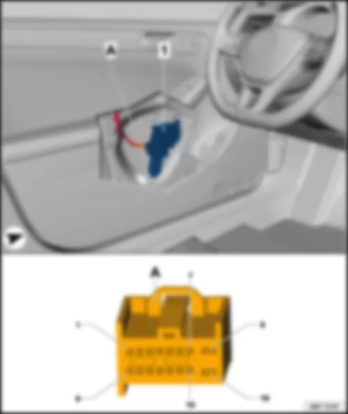
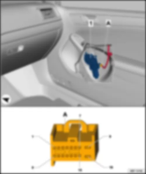
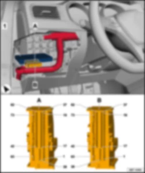
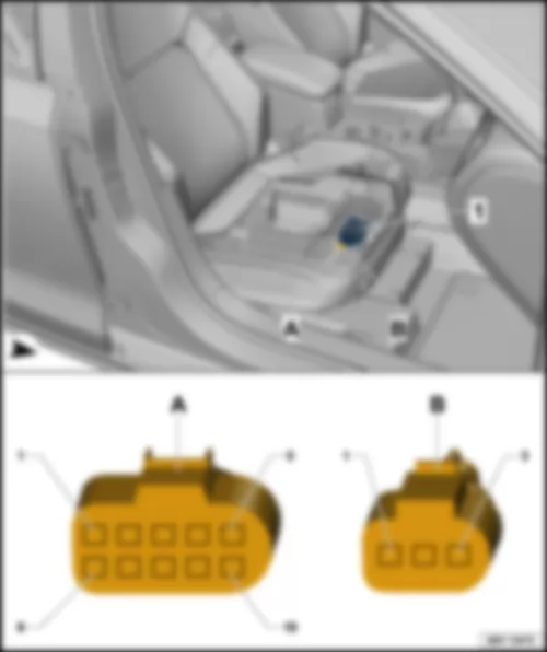
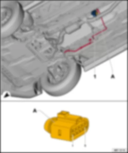
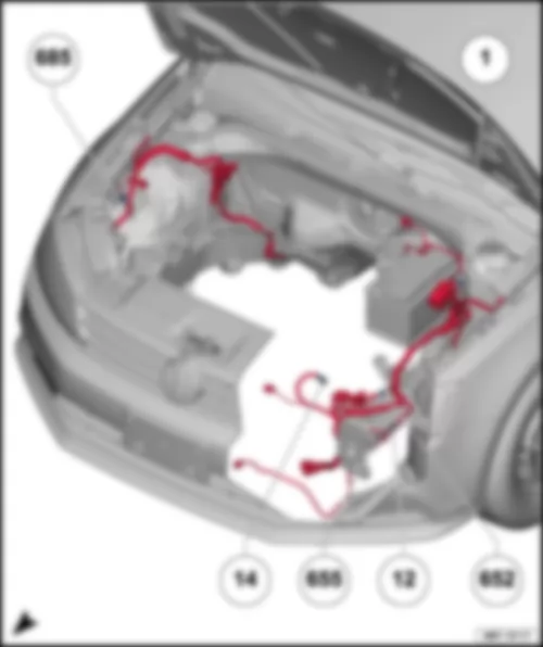
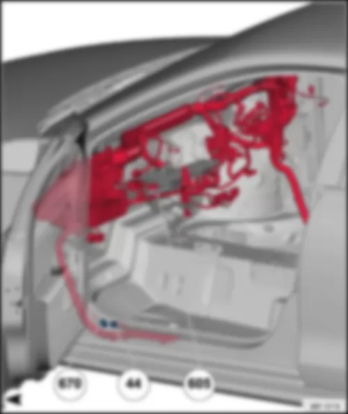
| 1 - | Airbag control unit -J234- | | A - | 75-pin connector -T75- |
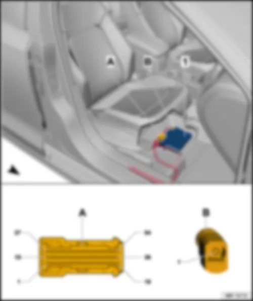
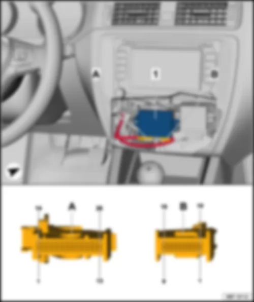
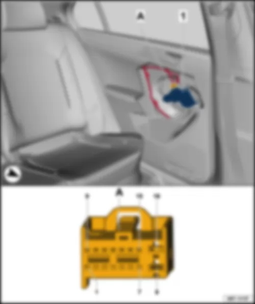
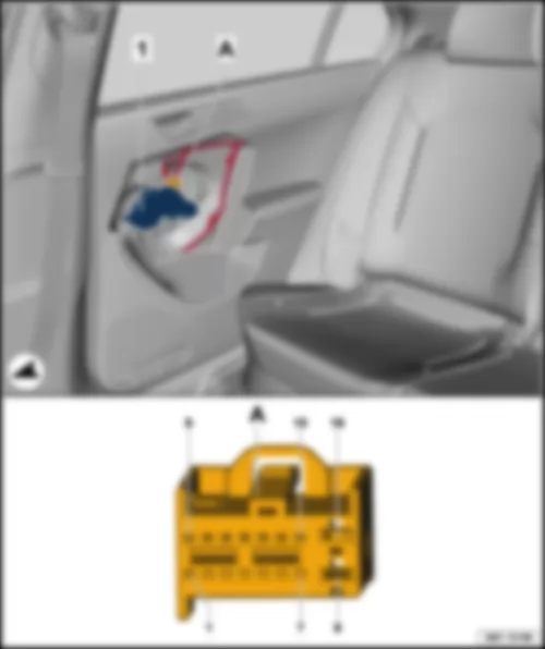
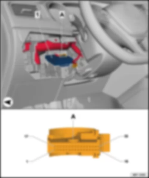
| 1 - | Airbag control unit -J234- | | A - | 100-pin connector -T100- |
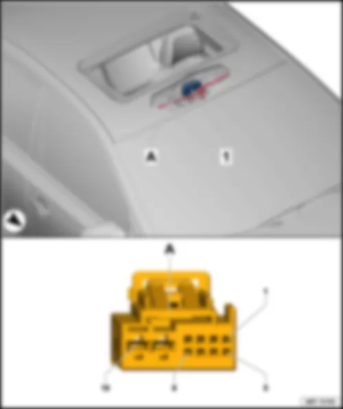
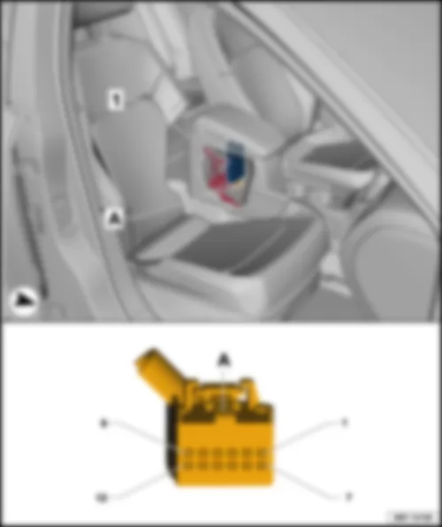
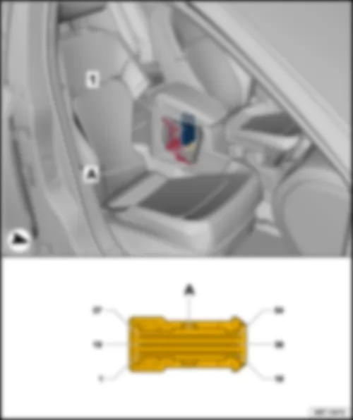
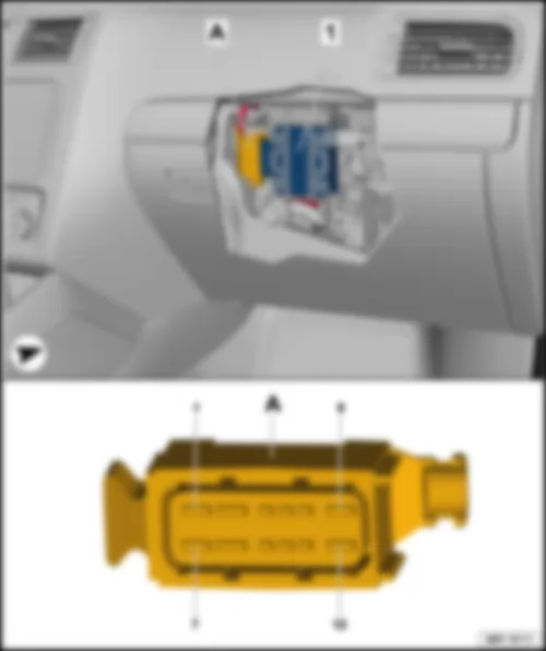
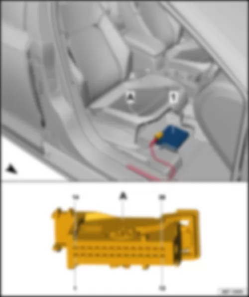
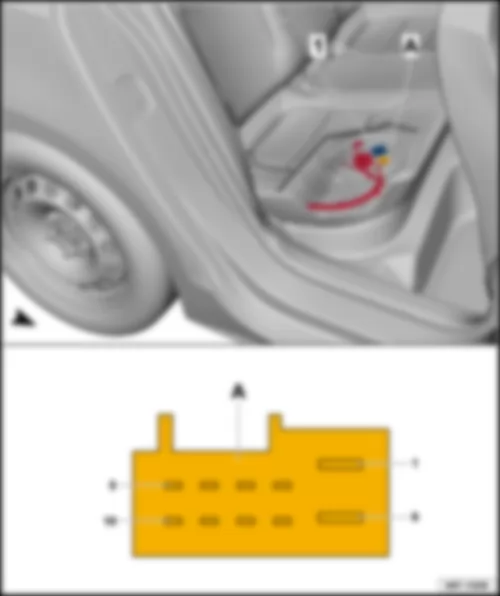
| Sliding sunroof adjustment control unit -J245- | | | | | 1 - | Sliding sunroof adjustment control unit -J245- | | A - | 10-pin connector -T10e- |
| Connector assignment, sliding sunroof adjustment control unit -J245- | | -T10e--A- | Designation | | -T10e--A- | Designation | | 1 | LIN | | 6 | | | 2 | Button 1 for tilting roof -E582- | | 7 | Button 1 for tilting roof -E582- | | 3 | Button 1 for tilting roof -E582- | | 8 | | | 4 | Button 1 for tilting roof -E582- | | 9 | Terminal 31 | | 5 | | | 10 | Terminal 30 |
VW JETTA 2017 Control unit in dash panel insert J285Control unit in dash panel insert -J285- |
| | | | 1 - | Control unit in dash panel insert -J285- | | A - | 32-pin connector -T32- |
| Connector assignment, control unit in dash panel insert -J285- | | -T32--A- | Designation | | -T32--A- | Designation | | -T32--A- | Designation | | 1 | Fuel pump control unit -J538- /
fuel delivery unit -GX1- | | 12 | | | 23 | Left steering column switch -EX19- /
right steering column switch -EX20- | | 2 | Fuel pump control unit -J538- /
fuel delivery unit -GX1- | | 13 | | | 24 | | | 3 | | | 14 | | | 25 | Handbrake warning switch -F9- | | 4 | | | 15 | B269 - Connection 2 (brake pad wear indicator), in interior wiring harness | | 26 | Brake fluid level warning contact -F34- | | 5 | | | 16 | Terminal 31 | | 27 | Oil pressure switch -F1- | | 6 | | | 17 | Windscreen washer fluid level sender -G33- | | 28 | B750 - Connection 1 (CAN bus, displays and controls, high) | | 7 | Immobiliser reader coil -D2- | | 18 | Coolant shortage indicator sender -G32- | | 29 | B751 - Connection 1 (CAN bus, displays and controls, low) | | 8 | Immobiliser reader coil -D2- | | 19 | Ambient temperature sensor -G17- | | 30 | | | 9 | | | 20 | B453 - Connection 1 (sensor), in main wiring harness | | 31 | Control unit for vehicle location system -J895- /
A20 - Positive connection (15a), in dash panel wiring harness | | 10 | | | 21 | Left steering column switch -EX19- /
right steering column switch -EX20- | | 32 | Terminal 30 | | 11 | Oil level and oil temperature sender -G266- | | 22 | Left steering column switch -EX19- /
right steering column switch -EX20- | | | |
VW JETTA 2017 Data bus diagnostic interface J533Data bus diagnostic interface -J533- |
| | | | 1 - | Data bus diagnostic interface -J533- | | A - | 20-pin connector -T20- |
| Connector assignment, data bus diagnostic interface -J533- | | -T20--A- | Designation | | -T20--A- | Designation | | 1 | B236 - Positive connection 6 (30a), in interior wiring harness | | 11 | 277 - Earth connection 3, in interior wiring harness | | 2 | B577 - LIN bus connection, in roof wiring harness | | 12 | Diagnostic connection -U31- /
D218 - Connection 1 (LIN bus) in engine compartment wiring harness | | 3 | | | 13 | | | 4 | | | 14 | A20 - Positive connection (15a), in dash panel wiring harness | | 5 | B406 - Connection 1 (convenience CAN bus, low), in main wiring harness | | 15 | B397 - Connection 1 (convenience CAN bus, high), in main wiring harness | | 6 | B390 - Connection 1 (powertrain CAN bus, low), in main wiring harness | | 16 | B383 - Connection 1 (powertrain CAN bus, high), in main wiring harness | | 7 | B109 - Connection 1 (CAN bus extended, low), in main wiring harness | | 17 | B108 - Connection 1 (CAN bus extended, high), in main wiring harness | | 8 | B751 - Connection 1 (CAN bus, displays and controls, low) | | 18 | B750 - Connection 1 (CAN bus, displays and controls, high) | | 9 | B714 - Connection 1 (diagnostic CAN bus, low), in main wiring harness | | 19 | B713 - Connection 1 (diagnostic CAN bus, high), in main wiring harness | | 10 | B421 - Connection 1 (infotainment CAN bus, low), in main wiring harness | | 20 | B415 - Connection 1 (infotainment CAN bus, high), in main wiring harness |
VW JETTA 2017 Fresh air blower control unit J126Fresh air blower control unit -J126- |
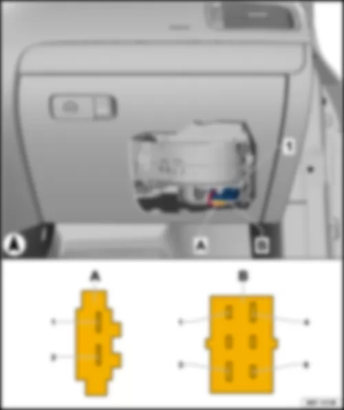
| Under dash panel, front passenger side | | | | | 1 - | Fresh air blower control unit -J126- | | A - | 2-pin connector -T2v- | | B - | 6-pin connector -T6t- |
| Connector assignment, fresh air blower control unit -J126- | | -T2v--A- | Designation | | -T6t--B- | Designation | | 1 | Heater control unit -J162- /fresh air blower control unit -J126- | | 1 | Climatronic control unit -J255- /air conditioning system control unit -J301- | | 2 | Terminal 31 | | 2 | Climatronic control unit -J255- /air conditioning system control unit -J301- | | | | | 3 | Terminal 31 | | | | | 4 | Terminal 30 | | | | | 5 | | | | | | 6 | |
VW JETTA 2017 Control unit for reducing agent metering system -J880- /control unit for reducing-agent heater -J891- |
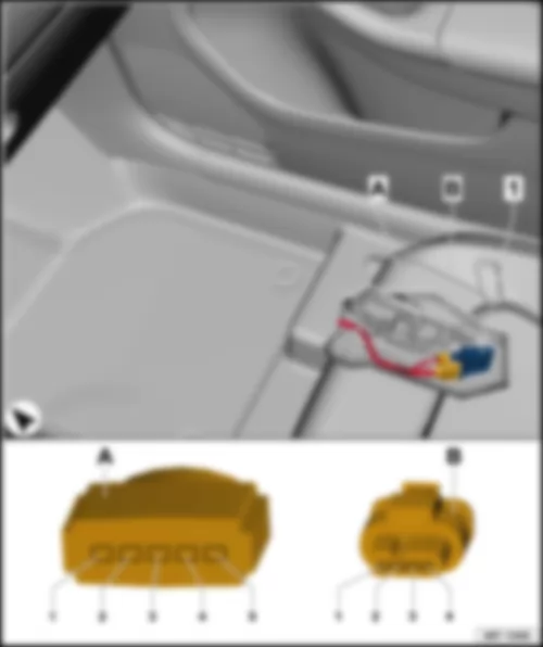
| Under front passenger seat. | | | | | 1 - | Control unit for reducing agent metering system -J880- | | 1 - | Control unit for reducing-agent heater -J891- | | A - | 5-pin connector -T5ax- | | B - | 4-pin connector -T4at- |
| Connector assignment of control unit for reducing agent metering system -J880- and control unit for reducing-agent heater -J891- | | -T5ax--A- | Designation | | -T4at--B- | Designation | | 1 | Heater for reducing-agent line (heater circuit 2) -Z104- | | 1 | Engine control unit -J623- | | 2 | | | 2 | Engine control unit -J623- | | 3 | Terminal 30 | | 3 | Engine control unit -J623- | | 4 | Delivery unit for reducing agent metering system -GX19- | | 4 | | | 5 | Terminal 30 | | | |
VW JETTA 2017 Multifunction steering wheel control unit J453Multifunction steering wheel control unit -J453- |
| in multifunction steering wheel | | | | | 1 - | Multifunction steering wheel control unit -J453- | | A - | 5-pin connector -T5n- | | B - | 12-pin connector -T12n- |
| Connector assignment of multifunction steering wheel control unit -J453- | | -T5n--A- | Designation | | -T12n--B- | Designation | | 1 | Terminal 31 | | 1 | | | 2 | Terminal 30 | | 2 | | | 3 | LIN bus | | 3 | Driver side airbag igniter -N95- , + | | 4 | | | 4 | Driver side airbag igniter -N95- , - | | 5 | | | 5 | | | | | | 6 | | | | | | 7 | Terminal 31 | | | | | 8 | Horn plate -H- | | | | | 9 | LIN bus | | | | | 10 | Terminal 30 | | | | | 11 | | | | | | 12 | |
VW JETTA 2017 Heated front seats control unit J774Heated front seats control unit -J774- |
| | | | 1 - | Heated front seats control unit -J774- | | A - | 8-pin connector -T8z- |
| Connector assignment of heated front seats control unit -J774- | | -T8z--A- | Designation | | 1 | Heated seat cushion for front passenger seat -Z8- | | 2 | Onboard supply control unit -J519- | | 3 | Terminal 30 | | 4 | Heater control unit -J162- /air conditioning system control unit -J301- /Climatronic control unit -J255- | | 5 | Heated driver seat -Z6- | | 6 | Terminal 30 | | 7 | Terminal 31 | | 8 | Driver seat temperature sensor -G59-
Heater control unit -J162- /air conditioning system control unit -J301- /Climatronic control unit -J255- |
VW JETTA 2017 Steering column electronics control unit J527Steering column electronics control unit -J527- |
| | | | 1 - | Steering column electronics control unit -J527- | | A - | 16-pin connector -T16l- | | B - | 4-pin connector -T4k- |
| Connector assignment of steering column electronics control unit -J527- | | -T16l--A- | Designation | | -T16l--A- | Designation | | -T4k--B- | Designation | | 1 | Terminal 30 | | 9 | | | 1 | Airbag control unit -J234- | | 2 | Terminal 31 | | 10 | | | 2 | Airbag control unit -J234- | | 3 | Convenience CAN, low | | 11 | Control unit for cornering light and headlight range control -J745-
Ignition/starter switch -D- | | 3 | | | 4 | Convenience CAN, high | | 12 | Powertrain CAN, low | | 4 | | | 5 | | | 13 | Powertrain CAN, high | | | | | 6 | Terminal 50 | | 14 | Onboard supply control unit -J519- | | | | | 7 | Radio -R- | | 15 | | | | | | 8 | | | 16 | | | | |
| 1) Depending on equipment |
VW JETTA 2017 Control unit for electronic steering column lock J764Control unit for electronic steering column lock -J764- |
| | | | 1 - | Control unit for electronic steering column lock -J764- | | A - | 16-pin connector -T16v- |
| Connector assignment of control unit for electronic steering column lock -J764- | | -T16v--A- | Designation | | -T16v--A- | Designation | | 1 | | | 9 | | | 2 | Terminal 30 | | 10 | 249 - Earth connection 2, in interior wiring harness | | 3 | Starter relay 2 -J907- | | 11 | | | 4 | Starter button -E378- | | 12 | B239 - Positive connection 1 (50), in interior wiring harness/
converter box -J935- /
D210 - Connection (50), in engine compartment wiring harness | | 5 | | | 13 | Starter button -E378- | | 6 | Converter box -J935- | | 14 | U3 - Connection 1, in automatic gearbox wiring harness | | 7 | Onboard supply control unit -J519- | | 15 | B406 - Connection 1 (convenience CAN bus, low), in main wiring harness | | 8 | A219 - Connection (S contact), in main wiring harness/
converter box -J935- | | 16 | B397 - Connection 1 (convenience CAN bus, high), in main wiring harness |
VW JETTA 2017 Amplifier R12Amplifier -R12- |
| | | | A - | 38-pin connector -T38- |
| Connector assignment of amplifier -R12- | | -T38--A- | Designation | | -T38--A- | Designation | | -T38--A- | Designation | | 1 | Terminal 31 | | 14 | Front left mid-range loudspeaker -R103- | | 27 | Radio -R- /control unit with display for radio and navigation -J503- | | 2 | Terminal 30 | | 15 | Front right bass loudspeaker -R23- | | 28 | Radio -R- /control unit with display for radio and navigation -J503- | | 3 | Front right bass loudspeaker -R23- | | 16 | Subwoofer -R211- | | 29 | Radio -R- /control unit with display for radio and navigation -J503- | | 4 | Subwoofer -R211- | | 17 | Subwoofer -R211- | | 30 | Radio -R- /control unit with display for radio and navigation -J503- | | 5 | Subwoofer -R211- | | 18 | Front left bass loudspeaker -R21- | | 31 | CAN high | | 6 | Front left bass loudspeaker -R21- | | 19 | Front right treble loudspeaker -R22- | | 32 | | | 7 | Front right treble loudspeaker -R22- | | 20 | Front left treble loudspeaker -R20- | | 33 | | | 8 | Front left treble loudspeaker -R20- | | 21 | Rear left bass loudspeaker -R15- | | 34 | | | 9 | Rear left bass loudspeaker -R15- | | 22 | Rear right bass loudspeaker -R17- | | 35 | Radio -R- /control unit with display for radio and navigation -J503- | | 10 | Rear right bass loudspeaker -R17- | | 23 | CAN low | | 36 | Radio -R- /control unit with display for radio and navigation -J503- | | 11 | Front right mid-range loudspeaker -R104- | | 24 | | | 37 | Radio -R- /control unit with display for radio and navigation -J503- | | 12 | Front right mid-range loudspeaker -R104- | | 25 | | | 38 | Radio -R- /control unit with display for radio and navigation -J503- | | 13 | Front left mid-range loudspeaker -R103- | | 26 | | | | |
VW JETTA 2017 Telephone transmitter and receiver unit R36Telephone transmitter and receiver unit -R36- |
| Under front passenger seat. | | | | | 1 - | Telephone transmitter and receiver unit -R36- | | A - | 54-pin connector -T54- | | B - | Single connector -T1aa- |
| Connector assignment of telephone transmitter and receiver unit -R36- | | -T54--A- | Designation | | -T54--A- | Designation | | -T54--A- | Designation | | 1 | Terminal 30 | | 19 | | | 37 | | | 2 | Terminal 31 | | 20 | | | 38 | Telephone bracket -R126- | | 3 | | | 21 | | | 39 | Terminal 31 | | 4 | Radio -R- /control unit with display for radio and navigation -J503- | | 22 | | | 40 | Telephone bracket -R126- | | 5 | Radio -R- /control unit with display for radio and navigation -J503- | | 23 | | | 41 | | | 6 | | | 24 | | | 42 | | | 7 | | | 25 | | | 43 | | | 8 | Radio -R- /control unit with display for radio and navigation -J503- | | 26 | | | 44 | | | 9 | Radio -R- /control unit with display for radio and navigation -J503- | | 27 | | | 45 | | | 10 | | | 28 | | | 46 | | | 11 | Telephone microphone -R38-Radio -R- /control unit with display for radio and navigation -J503-1) | | 29 | | | 47 | Telephone bracket -R126- | | 12 | Telephone microphone -R38-Radio -R- /control unit with display for radio and navigation -J503-1) | | 30 | Interior monitoring deactivation switch -E267- | | 48 | Telephone bracket -R126- | | 13 | | | 31 | Interior monitoring deactivation switch -E267- | | 49 | | | 14 | | | 32 | | | 50 | | | 15 | | | 33 | | | 51 | | | 16 | | | 34 | | | 52 | | | 17 | CAN high | | 35 | | | 53 | | | 18 | CAN low | | 36 | | | 54 | |
| 1) According to equipment |
VW JETTA 2017 Multimedia system control unit J650Multimedia system control unit -J650- |
| Multimedia system control unit -J650- , in front centre armrest | | In the front centre armrest | | | | | 1 - | Multimedia system control unit -J650- | | A - | 12-pin connector -T12h- |
| Connector assignment of multimedia system control unit -J650- . | | 1 - | Multimedia system control unit -J650- | | A - | 12-pin connector -T12h- |
| -T12h--A- | Designation | | -T12h--A- | Designation | | 1 | Terminal 31 | | 7 | Terminal 30 | | 2 | CAN low | | 8 | CAN high | | 3 | | | 9 | Radio -R- /control unit with display for radio and navigation -J503- | | 4 | Radio -R- /control unit with display for radio and navigation -J503- | | 10 | Radio -R- /control unit with display for radio and navigation -J503- | | 5 | Connection for external audio sources -R199- | | 11 | Connection for external audio sources -R199- | | 6 | Connection for external audio sources -R199- | | 12 | Shielding |
VW JETTA 2017 Mobile telephone operating electronics control unit J412Mobile telephone operating electronics control unit -J412- |
| Mobile telephone operating electronics control unit -J412- , in front centre armrest | | In the front centre armrest | | | | | 1 - | Mobile telephone operating electronics control unit -J412- | | A - | 54-pin connector -T54a- |
| Connector assignment of mobile telephone operating electronics control unit -J412- . | | 1 - | Mobile telephone operating electronics control unit -J412- | | A - | 54-pin connector -T54a- |
| Connector assignment of mobile telephone operating electronics control unit -J412- | | -T54a--A- | Designation | | -T54a--A- | Designation | | -T54a--A- | Designation | | 1 | Terminal 30 | | 19 | | | 37 | | | 2 | Terminal 31 | | 20 | | | 38 | Telephone bracket -R126- | | 3 | | | 21 | | | 39 | | | 4 | Radio -R- /control unit with display for radio and navigation -J503- | | 22 | Radio -R- /control unit with display for radio and navigation -J503- | | 40 | Telephone bracket -R126- | | 5 | Radio -R- /control unit with display for radio and navigation -J503- | | 23 | Radio -R- /control unit with display for radio and navigation -J503- | | 41 | | | 6 | Navigation system interface -R94-1) | | 24 | Radio -R- /control unit with display for radio and navigation -J503- | | 42 | | | 7 | Navigation system interface -R94-1) | | 25 | | | 43 | | | 8 | Radio -R- /control unit with display for radio and navigation -J503- | | 26 | | | 44 | | | 9 | Radio -R- /control unit with display for radio and navigation -J503- | | 27 | | | 45 | | | 10 | | | 28 | | | 46 | | | 11 | Radio -R- /control unit with display for radio and navigation -J503-
Telephone microphone -R38-
Navigation system interface -R94- | | 29 | | | 47 | Telephone bracket -R126- | | 12 | Telephone microphone -R38-
Navigation system interface -R94-1)Radio -R- /control unit with display for radio and navigation -J503- | | 30 | Emergency assistance call button -E276- | | 48 | Telephone bracket -R126- | | 13 | | | 31 | Emergency assistance call button -E276- | | 49 | | | 14 | | | 32 | | | 50 | | | 15 | | | 33 | Connection for external audio sources -R199- | | 51 | | | 16 | | | 34 | Connection for external audio sources -R199- | | 52 | | | 17 | CAN high | | 35 | Connection for external audio sources -R199- | | 53 | | | 18 | CAN low | | 36 | | | 54 | |
| 1) Only when fitted under centre armrest, front |
VW JETTA 2017 Control unit for cornering light and headlight range control J745Control unit for cornering light and headlight range control -J745- |
| | | | 1 - | Control unit for cornering light and headlight range control -J745- | | A - | 26-pin connector -T26b- |
| Connector assignment of control unit for cornering light and headlight range control -J745- | | -T26b--A- | Designation | | -T26b--A- | Designation | | 1 | | | 14 | | | 2 | B383 - Connection 1 (powertrain CAN bus, high), in main wiring harness | | 15 | | | 3 | B390 - Connection 1 (powertrain CAN bus, low), in main wiring harness | | 16 | | | 4 | C67 - Connection (CAN bus, high), in headlight wiring harness | | 17 | | | 5 | C68 - Connection (CAN bus, low), in headlight wiring harness | | 18 | | | 6 | | | 19 | | | 7 | Rear left vehicle level sender -G76- | | 20 | | | 8 | | | 21 | | | 9 | | | 22 | | | 10 | Rear left vehicle level sender -G76- | | 23 | Terminal 15 | | 11 | Rear left vehicle level sender -G76- | | 24 | Terminal 31 | | 12 | | | 25 | | | 13 | | | 26 | |
VW JETTA 2017 Control module with display for radio and navigation system -J503- /radio -R- |
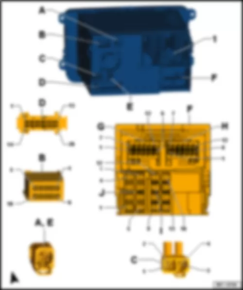
Note: | Multiway connector housing D (chambers: 9-16), made up of connectors E, F, G and H. | | 1 - | Control module with display for radio and navigation system -J503- /radio -R- | | q | Satellite aerial -R170- | | D - | 26-pin connector -T26a- | | F - | 16-pin connector -T16d- | | G - | 12-pin connector -T12f- | | H - | 12-pin connector -T12e- | | I - | 16-pin connector -T16d- | | J - | 8-pin connector -T8g- |
VW JETTA 2017 Voltage stabilizer J532Voltage stabilizer -J532- |
| | | | 1 - | Voltage stabilizer -J532- | | A - | 12-pin connector -T12d- |
| Connector assignment of voltage stabiliser -J532- | | -T12d--A- | Designation | | -T12d--A- | Designation | | 1 | Terminal 30 | | 7 | B246 - Positive connection (30a, stabilised), in interior wiring harness | | 2 | Terminal 31 | | 8 | | | 3 | Terminal 15 | | 9 | | | 4 | B660 - Connection (diagnosis terminal 50), in main wiring harness | | 10 | | | 5 | | | 11 | | | 6 | | | 12 | |
VW JETTA 2017 Parking aid control unit J446Parking aid control unit -J446- |
| Fitting location, left-hand drive | | Fitting location, right-hand drive | | On relay carrier under dash panel, driver side | | | | | 1 - | Parking aid control unit -J446- | | A - | 26-pin connector -T26d- | | B - | 18-pin connector -T18f- |
| Connector assignment of parking aid control unit -J446- | | -T26d--A- | Designation | | -T26d--A- | Designation | | -T18f--B- | Designation | | 1 | | | 19 | | | 1 | | | 2 | Front parking aid warning buzzer -H22- | | 20 | Rear centre left parking aid sender -G204- | | 2 | | | 3 | | | 21 | Rear right parking aid sender -G206- | | 3 | Front centre left parking aid sender -G254- | | 4 | | | 22 | 352 - Earth connection (parking aid), in rear bumper wiring harness | | 4 | Front right parking aid sender -G252- | | 5 | | | 23 | B390 - Connection 1 (powertrain CAN bus, low), in main wiring harness | | 5 | | | 6 | Rear left parking aid sender -G203- | | 24 | B383 - Connection 1 (powertrain CAN bus, high), in main wiring harness | | 6 | | | 7 | Rear centre right parking aid sender -G205- | | 25 | | | 7 | | | 8 | | | 26 | | | 8 | | | 9 | Rear parking aid warning buzzer -H15- | | | | | 9 | | | 10 | Front parking aid warning buzzer -H22- | | | | | 10 | 348 - Earth connection (parking aid), in front bumper wiring harness | | 11 | | | | | | 11 | Front left parking aid sender -G255- | | 12 | | | | | | 12 | Front centre right parking aid sender -G253- | | 13 | Terminal 31 | | | | | 13 | X65 - Connection (parking aid), in front bumper wiring harness | | 14 | Terminal 15 | | | | | 14 | | | 15 | Rear parking aid warning buzzer -H15- | | | | | 15 | | | 16 | Parking aid button -E266- | | | | | 16 | | | 17 | Parking aid button -E266- | | | | | 17 | | | 18 | X68 - Positive connection (parking aid), in rear bumper wiring harness | | | | | 18 | |
VW JETTA 2017 Heater and air conditioning system control unitHeater and air conditioning system control unit |
| 1 - | Heater control unit -J65- | | 1 - | Heater control unit -J162- | | A - | 20-pin connector -T20c- |
| Connector assignment of heater control unit -J65- /heater control unit -J162- | | -T20c--A- | Designation | | -T20c--A- | Designation | | -T5--B- | Designation | | 1 | Engine control unit -J623- | | 11 | Heated front seats control unit -J774- | | 1 | Fresh air blower series resistor with overheating fuse -N24- | | 2 | Engine control unit -J623- | | 12 | 5-pin connector -T5- | | 2 | Fresh air blower series resistor with overheating fuse -N24- | | 3 | Fresh air and air recirculation flap control motor -V154- | | 13 | | | 3 | Fresh air blower series resistor with overheating fuse -N24- | | 4 | 5-pin connector -T5- | | 14 | Auxiliary heater control unit -J364- | | 4 | Fresh air blower series resistor with overheating fuse -N24- /fresh air blower -V2- | | 5 | Auxiliary heater control unit -J364- | | 15 | B431 - Connection (seat heating), in main wiring harness | | 5 | Terminal 75/auxiliary heater operation relay -J485- | | 6 | Fresh air and air recirculation flap control motor -V154- | | 16 | | | | | | 7 | Engine control unit -J623- | | 17 | 5-pin connector -T5- | | | | | 8 | Onboard supply control unit -J519- | | 18 | Terminal 30 | | | | | 9 | | | 19 | Terminal 15 | | | | | 10 | D99 - Connection (coolant temperature), in engine compartment wiring harness | | 20 | Terminal 31 | | | |
| 1 - | Climatronic control unit -J255- | | A - | 16-pin connector -T16- | | B - | 16-pin connector -T16g- | | C - | 20-pin connector -T20c- |
| Connector assignment, Climatronic control unit -J255- | | -T16--A- | Designation | | -T16g--B- | Designation | | -T20c--C- | Designation | | 1 | Left temperature flap control motor -V158- | | 1 | Fresh air/air recirculation, air flow flap control motor -V425- /centre flap control motor -V70- /defroster flap control motor -V107- /left temperature flap control motor -V158- /right temperature flap control motor -V159- | | 1 | Sunlight penetration photosensor -G107- /sunlight penetration photosensor 2 -G134- | | 2 | Left temperature flap control motor -V158- | | 2 | Left temperature flap control motor -V158- | | 2 | High-pressure sender -G65- | | 3 | Defroster flap control motor -V107- | | 3 | Right temperature flap control motor -V159- | | 3 | Sunlight penetration photosensor -G107- /sunlight penetration photosensor 2 -G134- | | 4 | Defroster flap control motor -V107- | | 4 | Defroster flap control motor -V107- | | 4 | Air quality sensor -G238- | | 5 | Centre flap control motor -V70- | | 5 | Centre flap control motor -V70- | | 5 | B397 - Connection 1 (convenience CAN bus, high), in main wiring harness | | 6 | Centre flap control motor -V70- | | 6 | | | 6 | B406 - Connection 1 (convenience CAN bus, low), in main wiring harness | | 7 | | | 7 | Fresh air/air recirculation, air flow flap control motor -V425- | | 7 | | | 8 | | | 8 | Left footwell vent temperature sender -G261- | | 8 | | | 9 | Fresh air/air recirculation, air flow flap control motor -V425- | | 9 | Right footwell vent temperature sender -G262- | | 9 | Sunlight penetration photosensor -G107- /sunlight penetration photosensor 2 -G134- | | 10 | Fresh air/air recirculation, air flow flap control motor -V425- | | 10 | | | 10 | Heated front seats control unit -J774- | | 11 | Right temperature flap control motor -V159- | | 11 | Evaporator temperature sensor -G308- | | 11 | Heated front seats control unit -J774- | | 12 | Right temperature flap control motor -V159- | | 12 | | | 12 | | | 13 | | | 13 | | | 13 | Left vent temperature sender -G150- | | 14 | | | 14 | Fresh air/air recirculation, air flow flap control motor -V425- /centre flap control motor -V70- /defroster flap control motor -V107- /left temperature flap control motor -V158- /right temperature flap control motor -V159- /right footwell vent temperature sender -G262- /left footwell vent temperature sender -G261- /evaporator temperature sensor -G308- | | 14 | Right vent temperature sender -G151- | | 15 | Fresh air blower control unit -J126- | | 15 | | | 15 | | | 16 | Fresh air blower control unit -J126- | | 16 | | | 16 | LIN | | | | | | | | 17 | Sunlight penetration photosensor -G107- /sunlight penetration photosensor 2 -G134- /left vent temperature sender -G150- /right vent temperature sender -G151- | | | | | | | | 18 | Air conditioner compressor regulating valve -N280- | | | | | | | | 19 | Terminal 31 | | | | | | | | 20 | Terminal 15 |
| 1 - | Air conditioning system control unit -J301- | | A - | 20-pin connector -T20c- | | B - | 16-pin connector -T16e- |
| Connector assignment of air conditioning system control unit -J301- | | -T20c--A- | Designation | | -T16e--B- | Designation | | -T5--C- | Designation | | 1 | | | 1 | Temperature flap control motor -V68-1) | | 1 | Fresh air blower series resistor with overheating fuse -N24- | | 2 | | | 2 | Evaporator output temperature sender -G263- | | 2 | Fresh air blower series resistor with overheating fuse -N24- /auxiliary heater operation relay 2 -J1026- | | 3 | | | 3 | Air distribution flap control motor -V428-1) | | 3 | Fresh air blower series resistor with overheating fuse -N24- | | 4 | | | 4 | | | 4 | Fresh air blower -V2- /fresh air blower series resistor with overheating fuse -N24- | | 5 | High-pressure sender -G65- | | 5 | Temperature flap control motor -V68-1) | | 5 | Terminal 75/auxiliary heater operation relay -J485- | | 6 | | | 6 | | | | | | 7 | B406 - Connection 1 (convenience CAN bus, low), in main wiring harness | | 7 | Temperature flap control motor -V68-1) /air distribution flap control motor -V428-1) | | | | | 8 | B397 - Connection 1 (convenience CAN bus, high), in main wiring harness | | 8 | Evaporator output temperature sender -G263- /temperature flap control motor -V68-1) /air distribution flap control motor -V428-1) | | | | | 9 | | | 9 | Air recirculation flap control motor -V113- | | | | | 10 | | | 10 | Air recirculation flap control motor -V113- | | | | | 11 | | | 11 | Temperature flap control motor -V68-1) | | | | | 12 | Heated front seats control unit -J774- | | 12 | Air distribution flap control motor -V428-1) | | | | | 13 | Heated front seats control unit -J774- | | 13 | Air distribution flap control motor -V428-1) | | | | | 14 | | | 14 | | | | | | 15 | | | 15 | | | | | | 16 | Air conditioner compressor regulating valve -N280- | | 16 | | | | | | 17 | | | | | | | | | 18 | | | | | | | | | 19 | Terminal 30 | | | | | | | | 20 | Terminal 31 | | | | | | |
| 1) Only for air conditioning systems with electric control flaps | | Driver door control unit -J386- | | Driver door control unit -J386- , AW0 | | | | | 1 - | Driver door control unit -J386- | | A - | 16-pin connector -T16a- |
| Connector assignment, driver door control unit -J386- | | -T16a--A- | Designation | | -T16a--A- | Designation | | 1 | | | 9 | | | 2 | Rear right window regulator switch, in driver door -E55- | | 10 | Rear left window regulator switch, in driver door -E53- | | 3 | Warning light for activated childproof lock -K236- | | 11 | Childproof lock button -E318- | | 4 | Front right window regulator switch in driver door -E81- | | 12 | Fold-in mirror switch -E263- | | 5 | Lin | | 13 | | | 6 | Front left window regulator switch -E40- | | 14 | | | 7 | Output for switch earth | | 15 | | | 8 | Terminal 31 | | 16 | Terminal 30 |
| 1 - | Driver door control unit -J386- | | A - | 32-pin connector -T32a- | | B - | 16-pin connector -T16a- | | C - | 20-pin connector -T20a- |
| Connector assignment, driver door control unit -J386- | | -T32a--A- | Designation | | -T16a--B- | Designation | | -T20a--C- | Designation | | 1 | Driver side interior locking button for central locking system -E308- | | 1 | | | 1 | | | 2 | Central locking SAFELOCK function warning lamp -K133- | | 2 | | | 2 | Driver door central locking SAFELOCK function motor -V161- | | 3 | Warning light for activated childproof lock -K236- | | 3 | | | 3 | Driver door central locking motor -V56- /driver door central locking SAFELOCK function motor -V161- | | 4 | | | 4 | Driver side mirror adjustment motor -V149- | | 4 | | | 5 | | | 5 | Driver side exterior mirror -VX4- | | 5 | | | 6 | Fold-in mirror switch -E263- /mirror adjustment changeover switch -E48- | | 6 | | | 6 | Output for switch earth | | 7 | Rear right window regulator switch, in driver door -E55- | | 7 | Heated exterior mirror on driver side -Z4- | | 7 | Driver door contact switch -F2- | | 8 | Mirror adjustment switch -E43- | | 8 | | | 8 | CAN high | | 9 | | | 9 | | | 9 | CAN low | | 10 | | | 10 | | | 10 | | | 11 | | | 11 | Heated exterior mirror on driver side -Z4- /driver side turn signal repeater bulb -L131- | | 11 | | | 12 | | | 12 | Driver side mirror adjustment motor -V17- | | 12 | Driver door central locking motor -V56- /driver door central locking SAFELOCK function motor -V161- | | 13 | | | 13 | Driver side turn signal repeater bulb -L131- | | 13 | Driver door central locking motor -V56- | | 14 | Childproof lock button -E318- | | 14 | Driver side fold-in mirror motor -V121- | | 14 | | | 15 | Front right window regulator switch in driver door -E81- | | 15 | Driver side fold-in mirror motor -V121- | | 15 | Lin | | 16 | | | 16 | | | 16 | Driver side central locking lock unit -F220- | | 17 | | | | | | 17 | | | 18 | | | | | | 18 | Terminal 30 | | 19 | | | | | | 19 | Terminal 31 | | 20 | | | | | | 20 | Terminal 30 | | 21 | Output for switch earth | | | | | | | | 22 | | | | | | | | | 23 | Rear left window regulator switch, in driver door -E53- | | | | | | | | 24 | R75 - Connection (58d), 1 in door control unit wiring harness | | | | | | | | 25 | R75 - Connection (58d), 1 in door control unit wiring harness | | | | | | | | 26 | | | | | | | | | 27 | | | | | | | | | 28 | Exterior mirror heater button -E231- | | | | | | | | 29 | | | | | | | | | 30 | Rear lid remote release button -E233- | | | | | | | | 31 | Front left window regulator switch -E40- | | | | | | | | 32 | Driver side interior locking button for central locking system -E308- | | | | | | |
| Front passenger door control unit -J387- | | Front passenger door control unit -J387- , AW0 | | | | | 1 - | Front passenger door control unit -J387- | | A - | 16-pin connector -T16b- |
| Connector assignment, front passenger door control unit -J387- | | -T16b--A- | Designation | | -T16b--A- | Designation | | 1 | | | 9 | | | 2 | | | 10 | | | 3 | | | 11 | | | 4 | | | 12 | | | 5 | Lin | | 13 | | | 6 | Window regulator switch in front passenger door -E107- | | 14 | | | 7 | Output for switch earth | | 15 | | | 8 | Terminal 31 | | 16 | Terminal 30 |
| 1 - | Front passenger door control unit -J387- | | A - | 32-pin connector -T32b- | | B - | 16-pin connector -T16b- | | C - | 20-pin connector -T20b- |
| Connector assignment, front passenger door control unit -J387- | | -T32b--A- | Designation | | -T16b--B- | Designation | | -T20b--C- | Designation | | 1 | Front passenger side interior locking button for central locking system -E309- | | 1 | | | 1 | | | 2 | | | 2 | | | 2 | Front passenger door central locking SAFELOCK function motor -V162- | | 3 | | | 3 | | | 3 | Front passenger side central locking lock unit -F221- | | 4 | | | 4 | Front passenger side mirror adjustment motor -V150- | | 4 | | | 5 | | | 5 | Front passenger side exterior mirror -VX5- | | 5 | | | 6 | | | 6 | | | 6 | Output for switch earth | | 7 | | | 7 | Heated exterior mirror on front passenger side -Z5- | | 7 | Front passenger door contact switch -F3- | | 8 | | | 8 | | | 8 | CAN high | | 9 | | | 9 | | | 9 | CAN low | | 10 | | | 10 | | | 10 | | | 11 | | | 11 | Heated exterior mirror on front passenger side -Z5- /front passenger side turn signal repeater bulb -L132- | | 11 | | | 12 | | | 12 | Front passenger side mirror adjustment motor -V25- | | 12 | | | 13 | | | 13 | Front passenger side turn signal repeater bulb -L132- | | 13 | Front passenger door central locking motor -V57- | | 14 | | | 14 | Front passenger side fold-in mirror motor -V122- | | 14 | | | 15 | Window regulator switch in front passenger door -E107- | | 15 | Front passenger side fold-in mirror motor -V122- | | 15 | Lin | | 16 | | | 16 | | | 16 | | | 17 | | | | | | 17 | | | 18 | | | | | | 18 | Terminal 30 | | 19 | | | | | | 19 | Terminal 31 | | 20 | | | | | | 20 | Terminal 30 | | 21 | Output for switch earth | | | | | | | | 22 | | | | | | | | | 23 | | | | | | | | | 24 | Front passenger side interior locking button for central locking system -E309- | | | | | | | | 25 | Window regulator switch in front passenger door -E107- | | | | | | | | 26 | | | | | | | | | 27 | | | | | | | | | 28 | | | | | | | | | 29 | | | | | | | | | 30 | | | | | | | | | 31 | | | | | | | | | 32 | Front passenger side interior locking button for central locking system -E309- | | | | | | |
| Rear left door control unit -J388- | | Rear left door control unit -J388- , AW0 | | | | | 1 - | Rear left door control unit -J388- | | A - | 16-pin connector -T16h- |
| Pin assignment of rear left door control unit -J388- | | -T16h--A- | Designation | | -T16h--A- | Designation | | 1 | | | 9 | | | 2 | | | 10 | | | 3 | | | 11 | | | 4 | | | 12 | | | 5 | Lin | | 13 | | | 6 | Rear left window regulator switch, in door -E52- | | 14 | | | 7 | Output for switch earth | | 15 | | | 8 | Terminal 31 | | 16 | Terminal 30 |
| 1 - | Rear left door control unit -J388- | | A - | 18-pin connector -T18a- |
| Pin assignment of rear left door control unit -J388- | | -T18a--A- | Designation | | -T18a--A- | Designation | | 1 | Terminal 31 | | 10 | Terminal 30 | | 2 | Rear left window regulator switch, in door -E52- | | 11 | Terminal 30 | | 3 | Rear left central locking lock unit -F222- | | 12 | Lin | | 4 | | | 13 | | | 5 | Rear left door central locking motor, lock -V214- | | 14 | | | 6 | Rear left central locking lock unit -F222- | | 15 | Rear left central locking lock unit -F222- | | 7 | Rear left door contact switch -F10- | | 16 | Rear left window regulator switch, in door -E52- | | 8 | Rear central switch for interior locking -E286- | | 17 | Rear central switch for interior locking -E286- | | 9 | Terminal 31 | | 18 | Rear left window regulator switch, in door -E52- |
| Rear right door control unit -J389- | | Rear right door control unit -J389- , AW0 | | | | | 1 - | Rear right door control unit -J389- | | A - | 16-pin connector -T16i- |
| Pin assignment of rear right door control unit -J389- | | -T16i--A- | Designation | | -T16i--A- | Designation | | 1 | | | 9 | | | 2 | | | 10 | | | 3 | | | 11 | | | 4 | | | 12 | | | 5 | Lin | | 13 | | | 6 | Rear right window regulator switch, in door -E54- | | 14 | | | 7 | Output for switch earth | | 15 | | | 8 | Terminal 31 | | 16 | Terminal 30 |
| 1 - | Rear right door control unit -J389- | | A - | 18-pin connector -T18b- |
| Pin assignment of rear right door control unit -J389- | | -T18b--A- | Designation | | -T18b--A- | Designation | | 1 | Terminal 31 | | 10 | Terminal 30 | | 2 | Rear right window regulator switch, in door -E54- | | 11 | Terminal 30 | | 3 | Rear right central locking lock unit -F223- | | 12 | Lin | | 4 | | | 13 | | | 5 | Rear right door central locking motor, lock -V215- | | 14 | | | 6 | Rear right central locking lock unit -F223- | | 15 | Rear right central locking lock unit -F223- | | 7 | Rear right door contact switch -F11- | | 16 | Rear right window regulator switch, in door -E54- | | 8 | | | 17 | | | 9 | Terminal 31 | | 18 | Rear right window regulator switch, in door -E54- |
| Onboard supply control unit -J519- | | Onboard supply control unit -J519- , AW0 | | | | | 1 - | Onboard supply control unit -J519- | | A - | 73-pin connector -T73a- | | B - | 73-pin connector -T73b- |
| Connector assignment, onboard supply control unit -J519- | | -T73a--A- | Designation | | -T73b--B- | Designation | | 1 | Front right headlight -MX2- /
right headlight range control motor -V49- | | 1 | Front left headlight -MX1- /left headlight range control motor -V48- | | 2 | Front left headlight -MX1- /left headlight range control motor -V48- | | 2 | Front right headlight -MX2- /
right headlight range control motor -V49- | | 3 | | | 3 | Front left headlight -MX1- /
left headlight range control motor -V48- | | 4 | B154 - Connection 1 (DCt), in interior wiring harness | | 4 | A224 - Positive connection 2 (58), in dash panel wiring harness | | 5 | Front right headlight -MX2- /
right headlight range control motor -V49- | | 5 | Front left headlight -MX1- /left headlight range control motor -V48- | | 6 | Left tail light 2 -MX5- | | 6 | Front right headlight -MX2- /
right headlight range control motor -V49- | | 7 | Light switch -E1- /
rotary light switch -EX1- | | 7 | A224 - Positive connection 2 (58), in dash panel wiring harness | | 8 | Isolation relay for powertrain CAN bus -J788- | | 8 | Right steering column switch -EX20- /
left steering column switch -EX19- | | 9 | | | 9 | C69 - Front left connection (fog light), in main wiring harness | | 10 | Rear lid lock unit -F256- | | 10 | C25 - Connection (fog light), in front lighting wiring harness | | 11 | B466 - Connection 2 in main wiring harness | | 11 | Terminal 30 | | 12 | B465 - Connection 1 in main wiring harness | | 12 | W71 - Connection (reversing light), in rear wiring harness | | 13 | Tank filler flap locking motor -V155- | | 13 | Terminal 30 | | 14 | Terminal 31 | | 14 | C20 - Connection (left turn signal), in headlight wiring harness | | 15 | B467 - Connection 3 in main wiring harness | | 15 | C30 - Connection 2 (right turn signal), in headlight wiring harness | | 16 | Terminal 30 | | 16 | B131 - Connection (54), in interior wiring harness | | 17 | Rear left central locking lock unit -F222- | | 17 | B528 - Connection 1 (LIN bus) in main wiring harness | | 18 | Rear right central locking lock unit -F223- | | 18 | B390 - Connection 1 (powertrain CAN bus, low), in main wiring harness | | 19 | Driver door contact switch -F2- | | 19 | B383 - Connection 1 (powertrain CAN bus, high), in main wiring harness | | 20 | Front passenger door contact switch -F3- | | 20 | B397 - Connection 1 (convenience CAN bus, high), in main wiring harness | | 21 | Front passenger side central locking lock unit -F221- | | 21 | B406 - Connection 1 (convenience CAN bus, low), in main wiring harness | | 22 | Driver door central locking motor -V56- | | 22 | Diagnostic connection -U31- | | 23 | B605 - Connection 1, in interior wiring harness | | 23 | Diagnostic connection -U31- | | 24 | Rear left central locking lock unit -F222- | | 24 | B698 - Connection 3 (LIN bus) in main wiring harness | | 25 | B468 - Connection 4 in main wiring harness | | 25 | | | 26 | Rear right door contact switch -F11- | | 26 | | | 27 | Bonnet contact switch -F266- | | 27 | Right steering column switch -EX20- /
left steering column switch -EX19- | | 28 | Hazard warning lights button -E229-
Front passenger side central locking lock unit -F221-1) | | 28 | Front passenger side central locking lock unit -F221- | | 29 | Airbag coil connector and return ring with slip ring -F138- | | 29 | Light switch -E1- /
rotary light switch -EX1- | | 30 | 98 - Earth connection, in rear lid wiring harness | | 30 | | | 31 | | | 31 | Heater control unit -J65- | | 32 | Left steering column switch -EX19- | | 32 | Windscreen wiper motor -V- | | 33 | Left steering column switch -EX19- | | 33 | | | 34 | Rear left door contact switch -F10- | | 34 | A19 - Connection (58d), in dash panel wiring harness | | 35 | | | 35 | | | 36 | Heated front seats control unit -J774- | | 36 | Airbag coil connector and return ring with slip ring -F138- | | 37 | Light switch -E1- /
rotary light switch -EX1- | | 37 | | | 38 | Z1 - Connection 1, in mirror adjustment/heating wiring harness | | 38 | Terminal 31 | | 39 | | | 39 | U18 - Positive connection (30a), in automatic gearbox wiring harness | | 40 | B143 - Positive connection (58R), in interior wiring harness | | 40 | | | 41 | B144 - Positive connection (58L), in interior wiring harness | | 41 | | | 42 | Ignition/starter switch -D- /
control unit for electronic steering column lock -J764- | | 42 | | | 43 | B335 - Connection 1 (54), in main wiring harness | | 43 | Light switch -E1- /
rotary light switch -EX1- | | 44 | B149 - Positive connection 2 (15a), in interior wiring harness | | 44 | Left steering column switch -EX19- | | 45 | Light switch -E1- /
rotary light switch -EX1- | | 45 | B441 - Connection (CCS), in main wiring harness | | 46 | | | 46 | Left steering column switch -EX19- | | 47 | Entry and start authorisation control unit -J518- | | 47 | Left steering column switch -EX19- | | 48 | | | 48 | U27 - Connection (RL), in gearbox switch wiring harness | | 49 | | | 49 | B177 - Connection (61), in interior wiring harness | | 50 | | | 50 | Terminal 50 | | 51 | | | 51 | Terminal 75 | | 52 | B429 - Connection (EFPR), in main wiring harness | | 52 | Light switch -E1- /
rotary light switch -EX1- | | 53 | Alarm system relay 5, hazard warning lights -J464- | | 53 | Right steering column switch -EX20- /
left steering column switch -EX19- | | 54 | | | 54 | B750 - Connection 1 (CAN bus, displays and controls, high) | | 55 | Converter box -J935- | | 55 | U6 - Connection 2, in automatic gearbox wiring harness/
clutch position sender -G476- | | 56 | Hazard warning lights button -E229- | | 56 | | | 57 | | | 57 | B751 - Connection 1 (CAN bus, displays and controls, low) | | 58 | Central locking SAFELOCK function warning lamp -K133- | | 58 | Exterior mirror heater button -E231- | | 59 | | | 59 | Terminal 30 | | 60 | Heater control unit -J65- | | 60 | Terminal 31 | | 61 | | | 61 | B498 - Connection 1 (53c), in interior wiring harness | | 62 | Left steering column switch -EX19- | | 62 | Right steering column switch -EX20- /
left steering column switch -EX19- | | 63 | Terminal 30 | | 63 | B180 - Connection (heated rear window), in interior wiring harness | | 64 | Terminal 30 | | 64 | | | 65 | B559 - Positive connection 1 (30g) in main wiring harness | | 65 | | | 66 | Terminal 30 | | 66 | | | 67 | B727 - Connection (71a), in main wiring harness | | 67 | A1 - Positive connection (30a), in dash panel wiring harness | | 68 | Terminal 30 | | 68 | Terminal 30 | | 69 | Windscreen wiper motor -V- | | 69 | | | 70 | Terminal 31 | | 70 | | | 71 | Windscreen wiper motor -V- | | 71 | | | 72 | | | 72 | | | 73 | Terminal 30 | | 73 | |
| 1) Gradually discontinued | | 1 - | Onboard supply control unit -J519- | | A - | 52-pin connector -T52a- | | B - | 52-pin connector -T52b- | | C - | 52-pin connector -T52c- |
| Connector assignment, onboard supply control unit -J519- | | -T52a--A- | Designation | | -T52b--B- | Designation | | -T52c--C- | Designation | | 1 | Terminal 30 | | 1 | Terminal 30 | | 1 | Terminal 30 | | 2 | | | 2 | Tank filler flap locking motor -V155- | | 2 | Alarm system horn -H18- | | 3 | | | 3 | | | 3 | B143 - Positive connection (58R), in interior wiring harness | | 4 | | | 4 | | | 4 | Left tail light -MX3- | | 5 | Front left headlight -MX1- | | 5 | Tank filler flap locking motor -V155- /
fuel tank cap detection switch -F334- | | 5 | 367 - Earth connection 2, in main wiring harness | | 6 | Front left headlight -MX1- | | 6 | | | 6 | | | 7 | Front left headlight -MX1- | | 7 | | | 7 | Hazard warning lights button -E229- | | 8 | Front right headlight -MX2- | | 8 | | | 8 | | | 9 | C30 - Connection 2 (right turn signal), in headlight wiring harness | | 9 | | | 9 | | | 10 | Front left headlight -MX1- | | 10 | | | 10 | B154 - Connection 1 (DCt), in interior wiring harness | | 11 | Front left headlight -MX1- | | 11 | Rear lid electric opener motor -V254- /
rear lid lock unit -F256- | | 11 | | | 12 | | | 12 | Terminal 15 voltage supply relay -J329- | | 12 | | | 13 | Rear lid handle release button -E234- | | 13 | | | 13 | Control unit for electronic steering column lock -J764- /
A219 - Connection (S contact), in main wiring harness | | 14 | Bonnet contact switch -F266- | | 14 | Heater control unit -J65- | | 14 | Terminal 50 | | 15 | | | 15 | Switch and instrument illumination regulator -E20- | | 15 | B397 - Connection 1 (convenience CAN bus, high), in main wiring harness | | 16 | U27 - Connection (RL), in gearbox switch wiring harness | | 16 | | | 16 | B406 - Connection 1 (convenience CAN bus, low), in main wiring harness | | 17 | Rotary light switch -EX1- | | 17 | | | 17 | B335 - Connection 1 (54), in main wiring harness | | 18 | Rotary light switch -EX1- | | 18 | Wiper motor relay 1 -J368- | | 18 | | | 19 | Rotary light switch -EX1- | | 19 | | | 19 | | | 20 | Rotary light switch -EX1- | | 20 | Windscreen wiper motor -V- | | 20 | | | 21 | Rotary light switch -EX1- | | 21 | Heated front seats control unit -J774- | | 21 | A12 - Positive connection (75a), in dash panel wiring harness | | 22 | Rotary light switch -EX1- | | 22 | Heated rear window relay -J9- | | 22 | | | 23 | 367 - Earth connection 2, in main wiring harness | | 23 | Wiper motor relay 2 -J369- | | 23 | | | 24 | Terminal 30 | | 24 | Hazard warning lights button -E229- | | 24 | Entry and start authorisation control unit -J518- | | 25 | C69 - Front left connection (fog light), in main wiring harness | | 25 | | | 25 | C25 - Connection (fog light), in front lighting wiring harness | | 26 | Right tail light -MX4- | | 26 | | | 26 | Front left headlight -MX1- | | 27 | B144 - Positive connection (58L), in interior wiring harness | | 27 | | | 27 | A3 - Positive connection (58), in dash panel wiring harness | | 28 | Left tail light 2 -MX5- | | 28 | B491 - Positive connection (75), in interior wiring harness | | 28 | W71 - Connection (reversing light), in rear wiring harness | | 29 | B128 - Connection (luggage compartment light), in interior wiring harness | | 29 | B239 - Positive connection 1 (50), in interior wiring harness | | 29 | | | 30 | | | 30 | Switch and instrument illumination regulator -E20- | | 30 | U6 - Connection 2, in automatic gearbox wiring harness/
85 - Earth connection 1, in engine compartment wiring harness | | 31 | | | 31 | | | 31 | A219 - Connection (S contact), in main wiring harness | | 32 | Fuel tank cap detection switch -F334- | | 32 | | | 32 | Heater control unit -J65- /
B177 - Connection (61), in interior wiring harness | | 33 | Pressure equalisation button -E790- | | 33 | Rain and light sensor -G397- | | 33 | | | 34 | | | 34 | | | 34 | B660 - Connection (diagnosis terminal 50), in main wiring harness | | 35 | Heater control unit -J65- | | 35 | | | 35 | Switch and instrument illumination regulator -E20- | | 36 | Interior monitoring deactivation switch -E267- /
deactivation button for vehicle inclination sender -E360- | | 36 | B549 - Connection 2 (LIN bus) in main wiring harness | | 36 | | | 37 | | | 37 | Interior monitoring deactivation switch -E267- /
deactivation button for vehicle inclination sender -E360- | | 37 | | | 38 | | | 38 | B429 - Connection (EFPR), in main wiring harness | | 38 | | | 39 | | | 39 | | | 39 | | | 40 | | | 40 | Headlight washer system relay -J39- | | 40 | | | 41 | | | 41 | Headlight washer system relay -J39- | | 41 | | | 42 | 85 - Earth connection 1, in engine compartment wiring harness | | 42 | Terminal 30 | | 42 | Terminal 30 | | 43 | Washer pump -V5- | | 43 | B559 - Positive connection 1 (30g) in main wiring harness | | 43 | | | 44 | Front right headlight -MX2- | | 44 | | | 44 | | | 45 | High-level brake light bulb -M25- | | 45 | | | 45 | | | 46 | Tank filler flap locking motor -V155- | | 46 | | | 46 | Front right headlight -MX2- | | 47 | | | 47 | | | 47 | B448 - Connection (rear fog light), in main wiring harness | | 48 | | | 48 | | | 48 | Front left headlight -MX1- | | 49 | | | 49 | | | 49 | Front right headlight -MX2- | | 50 | | | 50 | B433 - Connection (footwell light), in main wiring harness | | 50 | Front right headlight -MX2- | | 51 | | | 51 | B340 - Connection 1 (58d), in main wiring harness/
A19 - Connection (58d), in dash panel wiring harness | | 51 | C20 - Connection (left turn signal), in headlight wiring harness | | 52 | | | 52 | 367 - Earth connection 2, in main wiring harness | | 52 | Front right headlight -MX2- |
| Entry and start authorisation control unit -J518- | | | | | 1 - | Entry and start authorisation control unit -J518- | | A - | 32-pin connector -T32e- |
| Connector assignment, entry and start authorisation control unit -J518- | | -T32e--A- | Designation | | -T32e--A- | Designation | | -T32e--A- | Designation | | 1 | | | 12 | | | 23 | Driver side aerial for entry and start system -R134- | | 2 | | | 13 | | | 24 | Driver side aerial for entry and start system -R134- | | 3 | Terminal 30 | | 14 | | | 25 | Luggage compartment aerial for entry and start system -R137- | | 4 | | | 15 | | | 26 | Passenger side aerial for entry and start system -R135- | | 5 | Front passenger door exterior handle contact sensor -G416- | | 16 | CAN low | | 27 | Rear bumper aerial for entry and start system -R136- | | 6 | | | 17 | Terminal 31 | | 28 | Interior aerial 1 for entry and start system -R138- | | 7 | | | 18 | Interior aerial 2 for entry and start system -R139- | | 29 | Interior aerial 2 for entry and start system -R139- | | 8 | | | 19 | Interior aerial 1 for entry and start system -R138- | | 30 | Starter button -E378- | | 9 | Driver door exterior handle contact sensor -G415- | | 20 | Rear bumper aerial for entry and start system -R136- | | 31 | | | 10 | Onboard supply control unit -J519- | | 21 | Passenger side aerial for entry and start system -R135- | | 32 | CAN high | | 11 | | | 22 | Luggage compartment aerial for entry and start system -R137- | | | |
VW JETTA 2017 Emergency call module control unit and communication unit J949Emergency call module control unit and communication unit -J949- |
| Under front passenger seat. | | | | | 1 - | Emergency call module control unit and communication unit -J949- | | A - | 26-pin connector -T26c- |
| Connector assignment of emergency call module control unit and communication unit -J949- | | -T26c--A- | Designation | | -T26c--A- | Designation | | 1 | Terminal 30 | | 14 | CAN high | | 2 | CAN low | | 15 | | | 3 | | | 16 | | | 4 | Telephone microphone -R38- | | 17 | Telephone microphone -R38- | | 5 | Mobile telephone operating electronics control unit -J412- /
radio -R- /
control unit with display for radio and navigation -J503- | | 18 | Mobile telephone operating electronics control unit -J412- /
radio -R- /
control unit with display for radio and navigation -J503- | | 6 | Emergency assistance call button -E276- | | 19 | Emergency assistance call button -E276- | | 7 | Emergency assistance call button -E276- | | 20 | Emergency assistance call button -E276- | | 8 | | | 21 | | | 9 | | | 22 | | | 10 | Mobile telephone operating electronics control unit -J412- | | 23 | | | 11 | Mobile telephone operating electronics control unit -J412- | | 24 | | | 12 | | | 25 | | | 13 | | | 26 | 490 - Earth connection (screening 2), in radio-navigation system wiring harness |
VW JETTA 2017 Fuel pump control unit J538Fuel pump control unit -J538- |
| | | | 1 - | Fuel pump control unit -J538- | | A - | 10-pin connector -T10n- |
| Connector assignment, fuel pump control unit -J538- | | -T10n--A- | Designation | | -T10n--A- | Designation | | 1 | Terminal 30 | | 6 | 87 - Earth connection 2, in rear wiring harness | | 2 | Engine control unit -J623- | | 7 | B429 - Connection (EFPR), in main wiring harness/
onboard supply control unit -J519-1) | | 3 | D52 - Positive connection (15a), in engine compartment wiring harness | | 8 | Control unit in dash panel insert -J285- | | 4 | Control unit in dash panel insert -J285- | | 9 | | | 5 | B453 - Connection 1 (sensor), in main wiring harness | | 10 | |
VW JETTA 2017 Seat occupied recognition control unit J706Seat occupied recognition control unit -J706- |
| Under front passenger seat. | | | | | 1 - | Seat occupied recognition control unit -J706- | | A - | 10-pin connector -T10t- | | B - | 3-pin connector -T3m- |
| Connector assignment, seat occupied recognition control unit -J706- | | -T10t--A- | Designation | | -T3m--B- | Designation | | 1 | | | 1 | A200 - Positive connection 5 (15a) in dash panel wiring harness | | 2 | | | 2 | Airbag control unit -J234- | | 3 | 475 - Earth connection (airbag), in main wiring harness | | 3 | 475 - Earth connection (airbag), in main wiring harness | | 4 | | | | | | 5 | | | | | | 6 | | | | | | 7 | Airbag control unit -J234- | | | | | 8 | | | | | | 9 | A200 - Positive connection 5 (15a) in dash panel wiring harness | | | | | 10 | Heated seat cushion for front passenger seat -Z8- | | | |
VW JETTA 2017 Exhaust flap control unit J883Exhaust flap control unit -J883- |
| | | | 1 - | Exhaust flap control unit -J883- | | A - | 5-pin connector -T5k- |
| Connector assignment, exhaust flap control unit -J883- | | -T5k--A- | Designation | | 1 | B369 - Connection 1 (5V), in main wiring harness | | 2 | D112 - Connection 10 in engine compartment wiring harness | | 3 | Engine control unit -J623- | | 4 | Engine control unit -J623- | | 5 | 104 - Earth connection in front right wiring harness - sensor earth - |
| | | | | | | | | | | | | | | | | | | | | | | |

