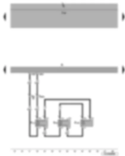
Wiring Diagram VW JETTA 2010 - Radio

| A | Battery |
| B | Starter |
| C | Alternator |
| ">J519 | ">Onboard supply control unit |
| R | Radio |
| SA1 | Fuse 1 on fuse holder/battery |
| SB8 | Fuse 8 on fuse holder |
| T16b | 16-pin connector |
| 507 | Screw connection (30), on fuse holder on battery |
| B224 | Connection 1 (radio), in interior wiring harness |
| * | Models with 90 A/ 110 A alternator |
| ** | Models with 140 A alternator |
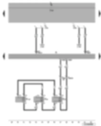
Wiring Diagram VW JETTA 2010 - Radio - front left loudspeaker
| ">J519 | ">Onboard supply control unit |
| R | Radio |
| R20 | Front left treble loudspeaker |
| R21 | Front left bass loudspeaker |
| R103 | Front left mid-range loudspeaker |
| T16b | 16-pin connector |
| T28 | 28-pin connector, coupling point, left A-pillar |
Wiring Diagram VW JETTA 2010 - Radio - front right loudspeaker - front right mid-range loudspeaker
| ">J519 | ">Onboard supply control unit |
| ">J533 | ">Data bus diagnostic interface |
| R | Radio |
| R22 | Front right treble loudspeaker |
| R23 | Front right bass loudspeaker |
| R104 | Front right mid-range loudspeaker |
| T16b | 16-pin connector |
| T20 | 20-pin connector |
| T28a | 28-pin connector, coupling point, right A-pillar |
| A178 | Connection (infotainment CAN bus, high), in dash panel wiring harness |
| A179 | Connection (infotainment CAN bus, low), in dash panel wiring harness |
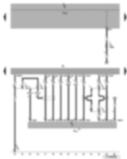
Wiring Diagram VW JETTA 2010 - Onboard supply control unit - radio - CD changer
| ">J519 | ">Onboard supply control unit |
| R | Radio |
| R41 | CD changer** |
| T12c | 12-pin connector |
| T12d | 12-pin connector* |
| T16b | 16-pin connector |
| 45 | Earth point, centre behind dash panel |
| 370 | Earth connection 5, in main wiring harness |
| 371 | Earth connection 6, in main wiring harness |
| B238 | Positive connection 2 (58b), in interior wiring harness |
| V14 | Connection (screening), in CD changer wiring harness |
| V45 | Connection 2 (screening), in CD changer wiring harness |
| * | only models with CD changer/ CD changer preparation |
| ** | Component does not exist in the preparation |
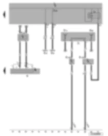
Wiring Diagram VW JETTA 2010 - Heater/heat output switch - heated rear window relay - onboard supply control unit - radio - aerial - radio aerial 2 - right aerial module - frequency modulation (FM) frequency filter in negative wire - frequency modulation (FM) frequency filter in positive wire
| E16 | Heater/heat output switch |
| J9 | Heated rear window relay |
| ">J519 | ">Onboard supply control unit |
| R | Radio |
| R11 | Aerial |
| R93 | Radio aerial 2 |
| R109 | Right aerial module |
| R178 | Frequency modulation (FM) frequency filter in negative wire |
| R179 | Frequency modulation (FM) frequency filter in positive wire |
| T20c | 20-pin connector |
| Z1 | Heated rear window |
| 51 | Earth point, on right in luggage compartment |
| 61 | Earth point, left C-pillar |
| * | only models without air conditioner |
VW JETTA 2010 Control units overview
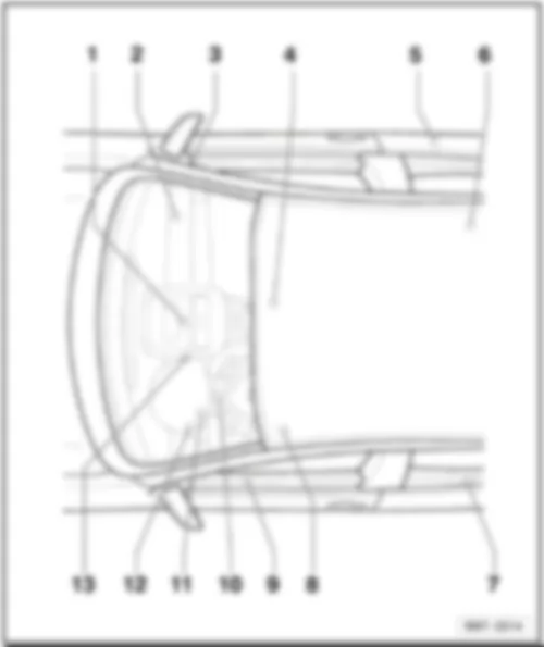
Control units overview | | | | q | Connector assigment, 50 pin |
| q | Connector assigment, 75 pin |
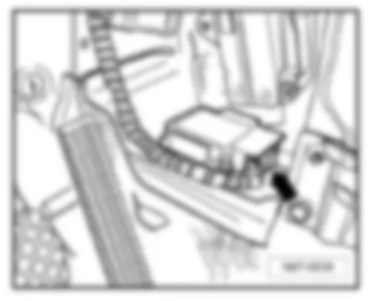
Location:
| Under front centre console -arrow- |
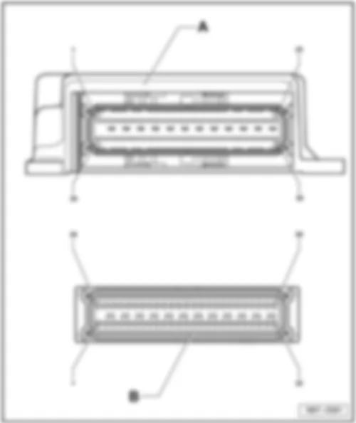
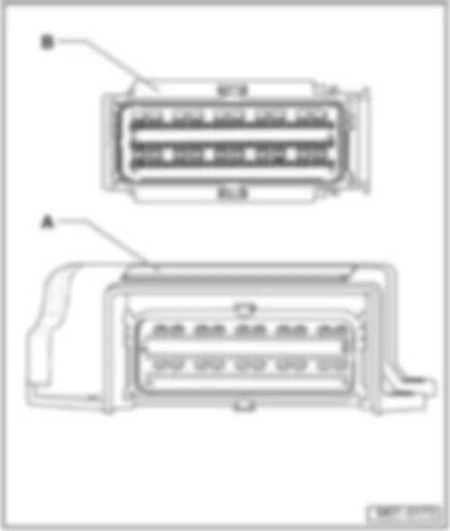
| | Connector assigment:
| A - | Airbag control unit -J234- |
| Jetta | Fitting Locations | No. 806 / 6 | | | A - | Airbag control unit -J234- | | Jetta | Fitting Locations | No. 806 / 7 | |
VW JETTA 2010 Convenience system central control unit -J393-Location: |
| Below the dash panel, behind the glove box -arrow- | | | | Connector assigment: | | A - | Convenience system central control unit - J393 | | Jetta | Fitting Locations | No. 806 / 9 | |
VW JETTA 2010 - G384 - Vehicle inclination sender |
VW JETTA 2010 Headlight range control, control unit -J431- | Headlight range control, control unit -J431- | | | | | A - | Headlight range control, control unit - J431 | | Jetta | Fitting Locations | No. 806 / 12 | |
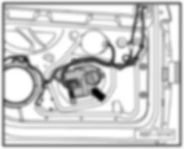
VW JETTA 2010 Front passenger side door control unit -J387-Location: |
| On door inner part on front right -arrow- | Note: | The illustration shows the left side. The right side is similar. | | | | Connector assigment: | | A - | Front passenger side door control unit -J387- | | Jetta | Fitting Locations | No. 806 / 14 | |
VW JETTA 2010 Mobile telephone operating electronics control unit -J412-Location: |
| Under seat on front right ⇒ -arrow- | | | | Connector assigment: | | A - | Mobile telephone operating electronics control unit -J412- | | Jetta | Fitting Locations | No. 806 / 16 | |
VW JETTA 2010 Heated front passenger seat control unit -J132-Heated front passenger seat control unit -J132- |
| | | | On seat frame on front right -arrow- |
VW JETTA 2010 Aerial selection control unit -J515-Aerial selection control unit -J515- |
| | | VW JETTA 2010 Rear right door control unit -J389- | Rear right door control unit -J389- | | | | | A - | Rear right door control unit -J389- | | Jetta | Fitting Locations | No. 806 / 19 | |
VW JETTA 2010 Fuel pump control unit -J538-Location: |
| Under rear seat, right, on fuel delivery unit -arrow- | | | | Connector assigment: | | A - | Fuel pump control unit -J538- | | Jetta | Fitting Locations | No. 806 / 21 | |
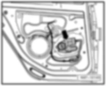
VW JETTA 2010 Rear left door control unit -J388-Location: |
| On door inner part on rear left -arrow- | | | | Connector assigment: | | A - | Rear left door control unit -J388- | | Jetta | Fitting Locations | No. 806 / 23 | |
VW JETTA 2010 Heated driver seat control unit -J131-Heated driver seat control unit -J131- |
| | | VW JETTA 2010 Driver door control unit -J386- | Driver door control unit -J386- | | | | | A - | Driver door control unit -J386- | | Jetta | Fitting Locations | No. 806 / 26 | |
VW JETTA 2010 Steering column electronics control unit -J527-Steering column electronics control unit -J527- |
| | | | A - | | Jetta | Fitting Locations | No. 806 / 28 | | | 11 - | Diagnostic interface for CAN data bus drive, low | | 12 - | Diagnostic interface for CAN data bus drive, high | | 13 - | Cruise control system, output |
| 14 - | Diagnostic interface for convenience CAN data bus, low | | 15 - | Diagnostic interface for convenience CAN data bus, high | | 16 - | Multifunction switch (automatic or direct shift gearbox only) |
F = Ignition/starter switch and ignition key withdrawal lock support: | | 3 - | Ignition key withdrawal lock terminal 30 | | 4 - | Ignition key withdrawal lock earth | | 7 - | Ignition/starter switch output terminal 50 | | 8 - | Ignition/starter switch terminal 30 | | 9 - | Ignition/starter switch output terminal S | | 10 - | Ignition/starter switch output terminal X | | 11 - | Ignition/starter switch output terminal P | | 12 - | Ignition/starter switch output terminal 15 |
| 3 - | Rear lid wash/wipe signal | | 6 - | Earth MFA, interval potentiometer | | 7 - | Intermittent operation speeds signal | | H= Steering angle sensor support: | | 4 - | 12 Volt voltage supply | | 5 - | 5 Volt voltage supply |
| 10 - | Photoelectric beam 7 | | I = Coil connector support: | | 7 - | Earth for coil connector, multifunction steering wheel and signal horn | | 9 - | LIN bus, heated steering wheel temperature sensor | | 10 - | Multifunction steering wheel voltage supply terminal 15 |
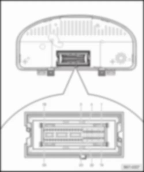
Connector assigment: | | - | Dash panel insert -J285- | | Jetta | Fitting Locations | No. 806 / 34 | | | 13 - | Diagnostic interface for combi CAN data bus, high | | 15 - | Diagnostic interface for combi CAN data bus exciter wire | | 16 - | Fuel gauge sender (4 Motion) | | 17 - | Fuel gauge sender (full) | | 18 - | Fuel gauge sender (empty) | | 22 - | Front left brake pad wear sender | | 24 - | Fuel tank flap lock warning lamp |
| 25 - | Oil pressure warning lamp | | 26 - | Oil level and oil temperature sender | | 28 - | Speed signal, sliding sunroof adjustment control unit output, control unit with display for radio and navigation system | | 33 - | Terminal 31, sensor earth | | 34 - | Washer fluid level warning lamp | | 35 - | Coolant temperature and coolant shortage warning lamp | | 36 - | Ambient temperature sensor |
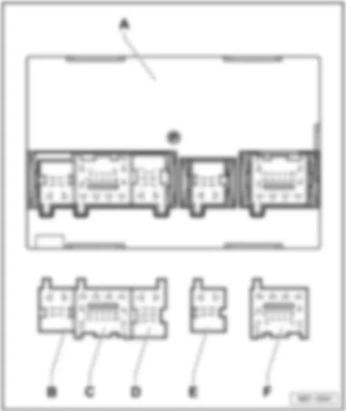
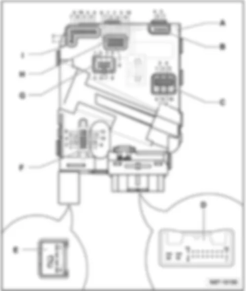
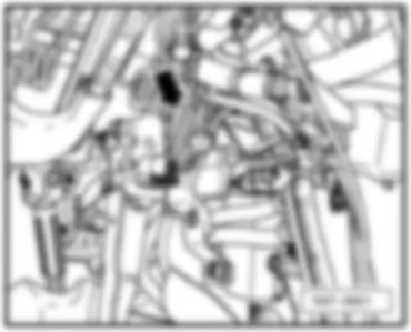
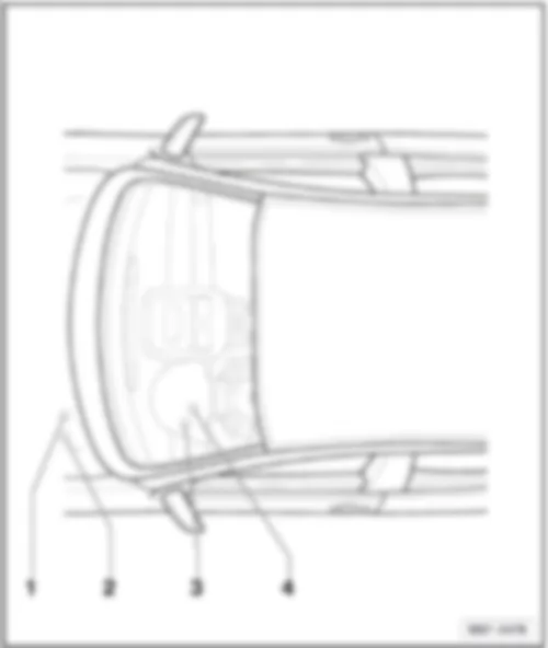
VW JETTA 2010 Onboard power supply control unit -J519- | Location: | | On left under dash panel, under relay carrier -arrow- | | | |
Connector assigment:
| - | Onboard power supply control unit -J519- |
| Jetta | Fitting Locations | No. 806 / 38 | | | 1 - | Right reversing light bulb | | 4 - | Rear left fog light bulb | | 5 - | Right brake and tail light bulb | | 7 - | Front left entry light, front right entry light | | 9 - | Right tail light bulb | | 10 - | Rear right turn signal bulb | | 11 - | Front interior light | | 1 - | Heated driver seat control unit, heated front passenger seat control unit | | 2 - | Left brake and tail light bulb |
| 9 - | High level brake light bulb | | 10 - | Left tail light bulb | | 11 - | Rear left turn signal bulb | | 4 - | Left dipped beam bulb | | 6 - | Left gas discharge (xenon) bulb | | 7 - | Terminal 15 voltage supply relay | | 8 - | Headlight washer system relay |
| 10 - | Right side light bulb | | 11 - | Front left turn signal bulb | | 1 - | Lighting switch terminal 58 | | 7 - | Earth (for manual gearbox only), mechatronics for direct shift gearbox (direct shift gearbox only), multifunction switch (for automatic gearbox only) | | 8 - | Lighting switch terminal 56 |
| 13 - | Light switch (rear fog light) | | 14 - | Light switch (assistance driving light) | | 16 - | Light switch (day driving light) | | 1 - | Terminal 50 voltage supply relay | | 2 - | Terminal 15 voltage supply relay | | 3 - | Windscreen wiper motor, rain and light detector sensor (LIN bus) | | 5 - | Bonnet contact switch | | 6 - | Reversing light switch |
| 1 - | Steering column electronics control unit terminal 50 | | 2 - | Hazard warning light system warning lamp | | 4 - | Illumination regulators, switches, instruments | | 6 - | Heated rear window button | | 7 - | Convenience CAN bus low | | 8 - | Convenience CAN bus high | | 9 - | Hazard warning light switch | | 10 - | Illumination regulators, switches, instruments | | 11 - | Steering column electronics control unit terminal 15 | | 12 - | Illumination regulators, switches, instruments | Note:
| 1 - | Fuse, windscreen washer pump | | 4 - | Windscreen washer pump motor | | 6 - | Treble tone horn, bass tone horn |
| 6 - | Heated rear window fuse |
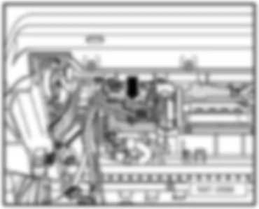
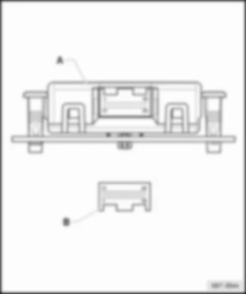
VW JETTA 2010 Data bus diagnostic interface -J533- | Location: |
| In left footwell, near centre console -arrow- |
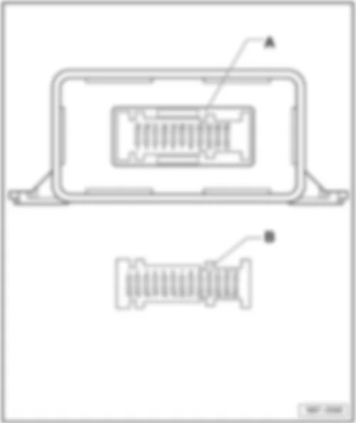
| | Connector assigment:
| A - | Data bus diagnostic interface -J533- |
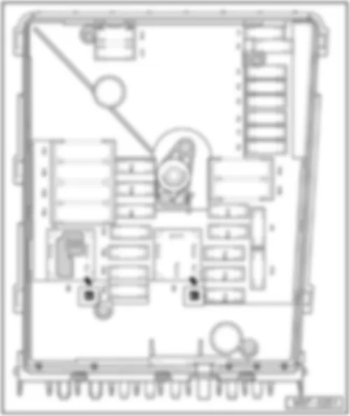
VW JETTA 2010 Overview of fuses (electronics box low) | Overview of fuses (electronics box low) |
| q | Position of fuses on electronics box | | q | Position of fuses on electronics box with 54 fuses, from May 2005 | | q | Position of fuses on electronics box with 54 fuses, from June 2006 | | q | Location of electronics box with 30 fuses, in left engine compartment | | q | Position of fuses of electronics box with 30 fuses, in left engine compartment, up to May 2005 | | q | Position of fuses of electronics box with 30 fuses, in left engine compartment, from July 2006 |
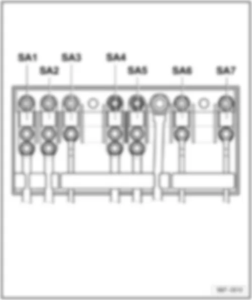
Location of fuses (SA), on electronics box |
| ⇒ Electrical system, Repair Group 97, removing and installing fuse holders |
VW JETTA 2010 Position of fuses electronics box
Position of fuses electronics box | | No. | | Current Flow Diagram designation | Nominal value | | Function/component | Terminal |
| 1 | - | SA1 - Fuse 1 on fuse holder battery | 150A
200A | - | C - Alternator (90A/110A)
C - Alternator (140A) | 30 |
| 2 | - | SA2 - Fuse 2 on fuse holder battery | 80A | - | V187 - Electromechanical power steering motor | 30 |
| 3 | - | SA3 - Fuse 3 on fuse holder battery | 50A | - | V7 - Radiator fan | 30 |
| 4 | - | SA4 - Fuse 4 on fuse holder battery | - | - | Vacant | - |
| 5 | - | SA5 - Fuse 5 on fuse holder battery | 80A | - | Fuses in fuse holder left dash panel
SC12, SC17, SC22, SC27, SC43, SC45 | 30 |
| 6 | - | SA6 - Fuse 6 on fuse holder battery | 100A | - | Z35 - Auxiliary heater element | 30 |
| 7 | - | SA7 - Fuse 7 on fuse holder battery | - | - | Vacant | - |
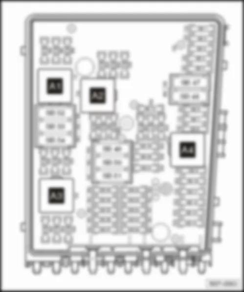
VW JETTA 2010 Fuses (SB) on electronics box with 54 fuses, on left of engine compartment
Fuses (SB) on electronics box with 54 fuses, on left of engine compartment | VW JETTA 2010 Position of fuses of electronics box with 54 fuses, from May 2005
Position of fuses of electronics box with 54 fuses, from May 2005 | | No. | | Current Flow Diagram designation | Nominal value | | Function/component | Terminal |
| F1 | - | SB1 - Fuse 1 on fuse holder | 30A | - | J104 - ABS control unit | 30 |
| F2 | - | SB2 - Fuse 2 on fuse holder | 30A | - | J104 - ABS control unit | 30 |
| F3 | - | SB3 - Fuse 3 on fuse holder | - | - | Vacant | 30 |
| F4 | - | SB4 - Fuse 4 on fuse holder | 5A | - | J519-Onboard power supply control unit | 30 |
| F5 | - | SB5 - Fuse 5 on fuse holder | 15A | - | J519-Onboard power supply control unit | 30 |
| F6 | - | SB6 - Fuse 6 on fuse holder | 15A | - | N276 - Fuel pressure regulating valve | 87 |
| F7 | - | SB7 - Fuse 7 on fuse holder | - | - | Vacant | 87 |
| F8 | - | SB8 - Fuse 8 on fuse holder | - | - | Vacant | 87 |
| F9 | - | SB9 - Fuse 9 on fuse holder | 10A | - | N75 - Charge pressure control solenoid valve
N80 - Activated charcoal filter system solenoid valve 1
N249 - Turbocharger air recirculation valve | 87 |
| F10 | - | SB10 - Fuse 10 on fuse holder | - | - | Vacant | 87 |
| F11 | - | SB11 - Fuse 11 on fuse holder | 10A | - | G39 - Lambda probe | 87 |
| F12 | - | SB12 - Fuse 12 on fuse holder | 10A | - | G130 - Lambda probe after catalytic converter | 87 |
| F13 | - | SB13 - Fuse 13 on fuse holder | 30A | - | J743 - Mechatronics for direct shift gearbox | 30 |
| F14 | - | SB14 - Fuse 14 on fuse holder | - | - | Vacant | 87 |
| F15 | - | SB15 - Fuse 15 on fuse holder | 10A | - | V55 - Circulation pump | 87 |
| F16 | - | SB16 - Fuse 16 on fuse holder | 5A | - | J527 - Steering column electronics control unit | 30 |
| F17 | - | SB17 - Fuse 17 on fuse holder | 5A | - | J285 - Control unit in dash panel insert | 30 |
| F18 | - | SB18 - Fuse 18 on fuse holder | 30A | - | J525 - Digital sound package control unit | 30 |
| Jetta | Fitting Locations | No. 802 / 7 |
|
| No. | | Current Flow Diagram designation | Nominal value | | Function/component | Terminal |
| F38 | - | SB38 - Fuse 38 on fuse holder | 10A | - | N205 - Inlet camshaft control valve 1
V7 - Radiator fan | 87 |
| F39 | - | SB39 - Fuse 39 on fuse holder | 5A | - | G476-Clutch position sender | 87 |
| F40 | - | SB40 - Fuse 40 on fuse holder | 20A | - | N70 - Ignition coil 1 with output stage
N127 - Ignition coil 2 with output stage
N291 - Ignition coil 3 with output stage
N292 - Ignition coil 4 with output stage | 87 |
| F41 | - | SB41 - Fuse 41 on fuse holder | - | - | Vacant | 87 |
| F42 | - | SB42 - Fuse 42 on fuse holder | 5A | - | J757 - Engine component current supply relay | 15 |
| F43 | - | SB43 - Fuse 43 on fuse holder | - | - | Vacant | 87 |
| F44 | - | SB44 - Fuse 44 on fuse holder | - | - | Vacant | - |
| F45 | - | SB45 - Fuse 45 on fuse holder | - | - | Vacant | - |
| F46 | - | SB46 - Fuse 46 on fuse holder | - | - | Vacant | - |
| F47 | - | SB47 - Fuse 47 on fuse holder | 30A | - | J519-Onboard power supply control unit | 30 |
| F48 | - | SB48 - Fuse 48 on fuse holder | 30A | - | J519-Onboard power supply control unit | 30 |
| F49 | - | SB49 - Fuse 49 on fuse holder | 40A | - | J329 - Terminal 15 voltage supply relay | 30 |
| F50 | - | SB50 - Fuse 50 on fuse holder | - | - | Vacant | 30 |
| F51 | - | SB51 - Fuse 51 on fuse holder | - | - | Vacant | 30 |
| F52 | - | SB52 - Fuse 52 on fuse holder | 50A | - | J59 - X-contact relief relay | 30 |
| F53 | - | SB53 - Fuse 53 on fuse holder | 50A | - | S44 - Driver seat adjustment thermal fuse 1
SC32 - Fuse 32 on fuse holder C | 30 |
| F54 | - | SB54 - Fuse 54 on fuse holder | - | - | Vacant | 30 |
VW JETTA 2010 Position of fuses of electronics box with 54 fuses, from July 2006
Position of fuses of electronics box with 54 fuses, from July 2006 | | No. | | Current Flow Diagram designation | Nominal value | | Function/component | Terminal |
| F1 | - | SB1 - Fuse 1 on fuse holder | 30A | - | J104 - ABS control unit | 30 |
| F2 | - | SB2 - Fuse 2 on fuse holder | 30A | - | J104 - ABS control unit | 30 |
| F3 | - | SB3 - Fuse 3 on fuse holder | - | - | Vacant | 30 |
| F4 | - | SB4 - Fuse 4 on fuse holder | 5A | - | J519-Onboard power supply control unit | 30 |
| F5 | - | SB5 - Fuse 5 on fuse holder | 15A | - | J519-Onboard power supply control unit | 30 |
| F6 | - | SB6 - Fuse 6 on fuse holder | 15A | - | N276 - Fuel pressure regulating valve | 87 |
| F7 | - | SB7 - Fuse 7 on fuse holder | - | - | Vacant | 87 |
| F8 | - | SB8 - Fuse 8 on fuse holder | - | - | Vacant | 87 |
| F9 | - | SB9 - Fuse 9 on fuse holder | 10A | - | N75 - Charge pressure control solenoid valve
N80 - Activated charcoal filter system solenoid valve 1
N249 - Turbocharger air recirculation valve | 87 |
| F10 | - | SB10 - Fuse 10 on fuse holder | - | - | Vacant | 87 |
| F11 | - | SB11 - Fuse 11 on fuse holder | 10A | - | G39 - Lambda probe | 87 |
| F12 | - | SB12 - Fuse 12 on fuse holder | 10A | - | G130 - Lambda probe after catalytic converter | 87 |
| F13 | - | SB13 - Fuse 13 on fuse holder | 30A | - | J743 - Mechatronics for direct shift gearbox | 30 |
| F14 | - | SB14 - Fuse 14 on fuse holder | - | - | Vacant | 87 |
| F15 | - | SB15 - Fuse 15 on fuse holder | 10A | - | V55 - Circulation pump | 87 |
| F16 | - | SB16 - Fuse 16 on fuse holder | 5A | - | J527 - Steering column electronics control unit | 30 |
| F17 | - | SB17 - Fuse 17 on fuse holder | 5A | - | J285 - Control unit in dash panel insert | 30 |
| F18 | - | SB18 - Fuse 18 on fuse holder | 30A | - | J525 - Digital sound package control unit | 30 |
| Jetta | Fitting Locations | No. 802 / 10 |
|
| No. | | Current Flow Diagram designation | Nominal value | | Function/component | Terminal |
| F38 | - | SB38 - Fuse 38 on fuse holder | 10A | - | N205 - Inlet camshaft control valve 1
V7 - Radiator fan | 87 |
| F39 | - | SB39 - Fuse 39 on fuse holder | 5A | - | G476-Clutch position sender | 87 |
| F40 | - | SB40 - Fuse 40 on fuse holder | 20A | - | N70 - Ignition coil 1 with output stage
N127 - Ignition coil 2 with output stage
N291 - Ignition coil 3 with output stage
N292 - Ignition coil 4 with output stage | 87 |
| F41 | - | SB41 - Fuse 41 on fuse holder | - | - | Vacant | 87 |
| F42 | - | SB42 - Fuse 42 on fuse holder | 5A | - | J757 - Engine component current supply relay | 15 |
| F43 | - | SB43 - Fuse 43 on fuse holder | - | - | Vacant | 87 |
| F44 | - | SB44 - Fuse 44 on fuse holder | - | - | Vacant | - |
| F45 | - | SB45 - Fuse 45 on fuse holder | - | - | Vacant | - |
| F46 | - | SB46 - Fuse 46 on fuse holder | - | - | Vacant | - |
| F47 | - | SB47 - Fuse 47 on fuse holder | 30A | - | J519-Onboard power supply control unit | 30 |
| F48 | - | SB48 - Fuse 48 on fuse holder | 30A | - | J519-Onboard power supply control unit | 30 |
| F49 | - | SB49 - Fuse 49 on fuse holder | 40A | - | J329 - Terminal 15 voltage supply relay | 30 |
| F50 | - | SB50 - Fuse 50 on fuse holder | - | - | Vacant | 30 |
| F51 | - | SB51 - Fuse 51 on fuse holder | - | - | Vacant | 30 |
| F52 | - | SB52 - Fuse 52 on fuse holder | 50A | - | J59 - X-contact relief relay | 30 |
| F53 | - | SB53 - Fuse 53 on fuse holder | 50A | - | S44 - Driver seat adjustment thermal fuse 1
SC32 - Fuse 32 on fuse holder C | 30 |
| F54 | - | SB54 - Fuse 54 on fuse holder | - | - | Vacant | 30 |
VW JETTA 2010 Fuses (SB) on electronics box, on left of engine compartment
Fuses (SB) on electronics box, on left of engine compartment | VW JETTA 2010 Position of fuses of electronics box with 30 fuses, up to May 2005
Position of fuses of electronics box with 30 fuses, up to May 2005 | | No. | | Current Flow Diagram designation | Nominal value | | Function/component | Terminal |
| F1 | - | SB1 - Fuse 1 on fuse holder | 30A | - | Vacant | 30 |
| F2 | - | SB2 - Fuse 2 on fuse holder | 5A | - | J527 - Steering column electronics control unit | 30 |
| F3 | - | SB3 - Fuse 3 on fuse holder | 5A | - | J519-Onboard power supply control unit | 30 |
| F4 | - | SB4 - Fuse 4 on fuse holder | 30A | - | J104 - ABS control unit | 30 |
| F5 | - | SB5 - Fuse 5 on fuse holder | 15A | - | J743 - Mechatronics for direct shift gearbox | 30 |
| F6 | - | SB6 - Fuse 6 on fuse holder | 5A | - | J285 - Control unit in dash panel insert | 30 |
| F7 | - | SB7 - Fuse 7 on fuse holder | - | - | Vacant | - |
| F8 | - | SB8 - Fuse 8 on fuse holder | 15A | - | J503 - Control unit with display for radio and navigation system
R - Radio
R146 - Satellite radio | 30 |
| F9 | - | SB9 - Fuse 9 on fuse holder | 5A | - | R36 - Telephone transmitter and receiver unit | 30 |
| F10 | - | SB10 - Fuse 10 on fuse holder | 5A
10A | - | J271 - Motronic current supply relay, engine codes BLF, BMY, BLG, BVY, BVZ
J317 - Terminal 30 voltage supply relay, engine codes BMY, BLG
J623 - Engine control unit, engine codes BLF, BMY, BLG, BVY, BVZ | 30 |
| Jetta | Fitting Locations | No. 802 / 14 |
|
| No. | | Current Flow Diagram designation | Nominal value | | Function/component | Terminal |
| F16 | - | SB16 - Fuse 16 on fuse holder | 30A | - | J104 - ABS control unit | 30 |
| F17 | - | SB17 - Fuse 17 on fuse holder | 15A | - | J519-Onboard power supply control unit | 30 |
| F18 | - | SB18 - Fuse 18 on fuse holder | 30A | - | J525 - Digital sound package control unit | 30 |
| F19 | - | SB19 - Fuse 19 on fuse holder | 30A | - | J400 - Wiper motor control unit | 30 |
| F20 | - | SB20 - Fuse 20 on fuse holder | - | - | Vacant | - |
| F21 | - | SB21 - Fuse 21 on fuse holder | 10A
15A
| - | G39 - Lambda probe, engine codes AZV, BKD, BKC, BLS, BMM
G39 - Lambda probe, engine codes BLF, BSE, BSF, BVY, BVZ
G108 - Lambda probe 2, engine codes BVY, BVZ
G130 - Lambda probe after catalytic converter, engine codes BLF, BSE, BSF
N421 - Magnetic clutch for supercharger, engine codes BMY, BLG | 87 |
| F22 | - | SB22 - Fuse 22 on fuse holder | 5A | - | G476-Clutch position sender | 87 |
| Jetta | Fitting Locations | No. 802 / 16 |
|
| No. | | Current Flow Diagram designation | Nominal value | | Function/component | Terminal |
| F25 | - | SB25 - Fuse 25 on fuse holder | 40A | - | J519-Onboard power supply control unit | 30 |
| F26 | - | SB26 - Fuse 26 on fuse holder | 40A | - | J519-Onboard power supply control unit | 30 |
| F27 | - | SB27 - Fuse 27 on fuse holder | 50A | - | J179 - Automatic glow period control unit, engine codes BKC, BLS, BMN
V101 - Secondary air pump motor, engine code BSE | 87 |
| F28 | - | SB28 - Fuse 28 on fuse holder | 40A | - | J329 - Terminal 15 voltage supply relay | 30 |
| F29 | - | SB29 - Fuse 29 on fuse holder | 50A | - | S44 - Driver seat adjustment thermal fuse 1
SC32 - Fuse 34 on fuse holder C | 30 |
| F30 | - | SB30 - Fuse 30 on fuse holder | 50A | - | J59 - X-contact relief relay | 30 |
VW JETTA 2010 Position of fuses of electronics box with 30 fuses, from July 2006
| Jetta | Fitting Locations | No. 802 / 18 | | | No. | | Current Flow Diagram designation | Nominal value | | Function/component | Terminal | | F13 | - | SB13 - Fuse 13 on fuse holder | 15A | - | J623 - Engine control unit (T94/3), (T94/5), (T94/6), engine codes BLG, BMY, BLF, BSE, BSF, BVY, BVZ, CAXA | 87 | | F13 | - | SB13 - Fuse 13 on fuse holder | 30A | - | J623 - Engine control unit (T94/3), (T94/5), (T94/6), engine codes AZV, BKC,BKD, BLS, BMM, BXE
J743 - Mechatronic unit for dual clutch gearbox, engine codes AZV, BKC,BKD, BLS, BMM, BXE | 87 | | F14 | - | SB14 - Fuse 14 on fuse holder | 20 | - | N70 - Ignition coil 1 with output stage
Engine codes BLG, BMY, BLF, BVY, BVZ, CAXA, BSE, BSF
N127 - Ignition coil 2 with output stage
Engine codes BLG, BMY, BLF, BVY, BVZ, CAXA, BSE, BSF
N152 - Ignition transformer, engine code BSE
N291 - Ignition coil 3 with output stage
Engine codes BLG, BMY, BLF, BVY, BVZ, CAXA, BSE, BSF
N292 - Ignition coil 4 with output stage
Engine codes BLG, BMY, BLF, BVY, BVZ, CAXA, BSE, BSF | 87 |
| Jetta | Fitting Locations | No. 802 / 20 | | | No. | | Current Flow Diagram designation | Nominal value | | Function/component | Terminal | | F19 | - | SB19 - Fuse 19 on fuse holder | 30A | - | J400 - Wiper motor control unit (T4p/1) | 30 | | F20 | - | SB20 - Fuse 20 on fuse holder | 40A | - | V50-Coolant circulation pump | - | | F21 | - | SB21 - Fuse 21 on fuse holder | 10A
15A
| - | G39 - Lambda probe, engine codes BSE, BSF, BLG, BMY, CAXA
G39 - Lambda probe, engine codes BLF, BSE, BSF, BVY, BVZ
G108 - Lambda probe 2, engine codes BVZ, BVY
G130 - Lambda probe after catalytic converter, engine codes
N421 - Magnetic clutch for supercharger, engine codes BLG, BMY, CAXA | 87 | | F22 | - | SB22 - Fuse 22 on fuse holder | 5A | - | G476-Clutch position sender | 87 |
| Jetta | Fitting Locations | No. 802 / 22 | | | No. | | Current Flow Diagram designation | Nominal value | | Function/component | Terminal | | F25 | - | SB25 - Fuse 25 on fuse holder | 40A | - | J519 - Onboard power supply control unit (A/1) | 30 | | F26 | - | SB26 - Fuse 26 on fuse holder | 40A | - | J519 - Onboard power supply control unit (D/1) | 30 | | F27 | - | SB27 - Fuse 27 on fuse holder | 50A
40A | - | J179 - Automatic glow period control unit, engine codes AZV, BKC, BKD, BLS, BMM, BMN
V101 - Secondary air pump motor, engine code BSE | 87 | | F28 | - | SB28 - Fuse 28 on fuse holder | 40A | - | J329 - Terminal 15 voltage supply relay
J59 - X-contact relief relay (l/1) | 30 | | F29 | - | SB29 - Fuse 29 on fuse holder | 50A | - | S44 - Driver seat adjustment thermal fuse 1
SC32 - Fuse 34 on fuse holder C | 30 | | F30 | - | SB30 - Fuse 30 on fuse holder | 50A | - | J59 - X-contact relief relay (l/1) | 30 |
VW JETTA 2010 Position of fuses electronics box | Position of fuses electronics box | | No. | | Current Flow Diagram designation | Nominal value | | Function/component | Terminal |
| 1 | - | SA1 - Fuse 1 on fuse holder battery | 150A
200A | - | C - Alternator (90A/110A)
C - Alternator (140A) | 30 |
| 2 | - | SA2 - Fuse 2 on fuse holder battery | 80A | - | V187 - Electromechanical power steering motor | 30 |
| 3 | - | SA3 - Fuse 3 on fuse holder battery | 50A | - | V7 - Radiator fan | 30 |
| 4 | - | SA4 - Fuse 4 on fuse holder battery | 80A | - | J360 - High heat output relay | - |
| 5 | - | SA5 - Fuse 5 on fuse holder battery | 80A | - | Fuses in fuse holder left dash panel
SC12, SC13, SC14, SC15, SC16, SC17, SC22, SC23, SC24, SC25, SC26, SC27, SC43, SC44, SC45 | 30 |
| 6 | - | SA6 - Fuse 6 on fuse holder battery | 100A | - | J359 - Low heat output relay | 30 |
| 7 | - | SA7 - Fuse 7 on fuse holder battery | - | - | Vacant | - |
VW JETTA 2010 Position of fuses of electronics box with 30 fuses, from July 2009
| Jetta | Fitting Locations | No. 802 / 25 | | | No. | | Current Flow Diagram designation | Nominal value | | Function/component | Terminal | | F13 | - | SB13 - Fuse 13 on fuse holder | 30A | - | J623 - Engine control unit (T94/3), (T94/5), (T94/6), engine codes BXE, CAYC, CAYB | 87 | | F13 | - | SB13 - Fuse 13 on fuse holder | 30A | - | J623 - Engine control unit (T94/3), (T94/5), (T94/6), engine code CAWB | 87 | | F13 | - | SB13 - Fuse 13 on fuse holder | 15A | - | J623 - Engine control unit (T94/3), (T94/5), (T121/3)
Engine codes BSE, CCSA, CAVD, CAXA | 87 | | F14 | - | SB14 - Fuse 14 on fuse holder | 20 | - | N70 - Ignition coil 1 with output stage, engine codes CAXA, CAWB, CAVD
N127 - Ignition coil 2 with output stage, engine codes CAXA, CAWB, CAVD
N152 - Ignition transformer, engine codes BSE, CCSA, BSF
N276 - Fuel pressure regulating valve, engine codes CAYC, CAYB, CBDA, CBDB, CEGA
N290 - Fuel metering valve, engine codes CAYC, CAYB, CBDA, CBDB, CEGA
N291 - Ignition coil 3 with output stage, engine codes CAXA, CAWB, CAVD
N292 - Ignition coil 4 with output stage, engine codes CAXA, CAWB, CAVD | 87 |
| Jetta | Fitting Locations | No. 802 / 27 | | | No. | | Current Flow Diagram designation | Nominal value | | Function/component | Terminal | | F19 | - | SB19 - Fuse 19 on fuse holder | 30A | - | J400 - Wiper motor control unit (T4p/1) | 30 | | F20 | - | SB20 - Fuse 20 on fuse holder | 40A | - | V50 - Coolant circulation pump, engine codes CAUD, CAXA
N276 - Fuel pressure regulating valve, engine code CAWB | - | | F21 | - | SB21 - Fuse 21 on fuse holder | 10A
15A
| - | G39 - Lambda probe, engine codes CAYC, CAYB
G39 - Lambda probe, engine codes (T6w/4) CBDA, CBDB, CEGA
G39 - Lambda probe, engine codes (T6w/3) BSE, CCSA, BSF
G39 - Lambda probe, engine codes (T4am/1) CAWB
G130 - Lambda probe after catalytic converter, engine codes (T4au/1) BSE, CCSA, BSF
V50 - Coolant circulation pump, engine code CAVD | 87 | | F22 | - | SB22 - Fuse 22 on fuse holder | 5A | - | G476 - Clutch position sender (T5m/5) | 87 |
| Jetta | Fitting Locations | No. 802 / 29 | | | F23 | - | SB23 - Fuse 23 on fuse holder | 15A | - | J151 - Continued coolant circulation relay, engine code CAWB
N276 - Fuel pressure regulating valve, engine codes CAVD, CAXA | 87 | | F24 | - | SB24 - Fuse 24 on fuse holder | 10A | - | J160 - Circulation pump relay, engine code CAVD
J299 - Secondary air pump relay, engine codes BSE, CCSA
J496 - Additional coolant pump relay, engine code CAXA
J757 - Engine component current supply relay, engine code CAWB
N75 - Charge pressure control solenoid valve, engine code CAVD
N156 - Variable intake manifold changeover valve, engine codes BSE, CCSA, BSF
N180 - Change-over valve, engine codes BSE, CCSA, BSF, CAVD
N205 - Inlet camshaft control valve 1, engine code CAVD
N249 - Turbocharger air recirculation valve, engine code CAVD
V7 - Radiator fan
V157 - Intake manifold flap motor, engine code BXE | 87 |
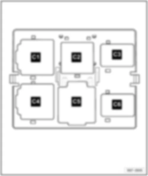
VW JETTA 2010 Overview of relay carrier | Overview of relay carrier | | | | q | Position of relays of electronics box with 30 fuses |
| 3 - | Relay carrier on onboard power supply control unit, under left dash panel |
Relay position assignment on additional relay carrier under electronics box in left engine compartment
| C2 - | Automatic glow period control unit -J179- (461) |
Note:
| The additional relay carrier is located under the electronics box and is only visible when it is removed. |
VW JETTA 2010 Position of relays of electronics box with 54 fuses
Position of relays of electronics box with 54 fuses | | A1 - | Motronic current supply relay -J271- (100) |
| A2 - | Continued coolant circulation relay -J151- (100) |
| A4 - | Engine component current supply relay -J757- (167) |
VW JETTA 2010 Position of relays of electronics box with 30 fuses
Position of relays of electronics box with 30 fuses | | A1 - | Motronic current supply relay -J271- (100) |
| - | Terminal 30 voltage supply relay -J317- (458) |
| q | Engine codes AZV, BKC, BKD, BLS, BMM |
| - | Current supply relay for Simos control unit -J363- (458) |
| A2 - | Secondary air pump relay -J299- (100) |
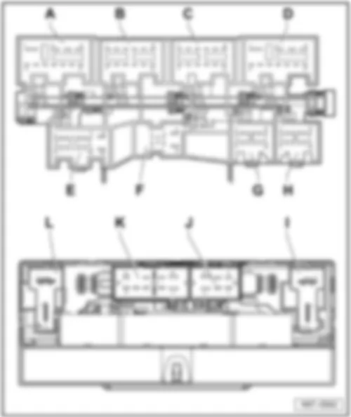
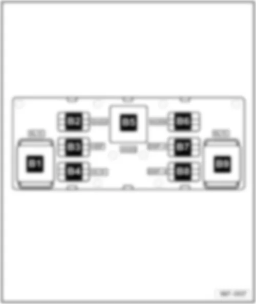
VW JETTA 2010 Position of relays, relay carrier on onboard power supply control unit, under left dash panel
Position of relays, relay carrier on onboard power supply control unit, under left dash panel | | B1 - | Terminal 15 voltage supply relay -J329- (460) |
| B4 - | Terminal 30 voltage supply relay -J317- (449) |
| B5 - | Heated rear window relay -J9- (53) |
| B6 - | Dual tone horn relay -J4- (449) |
| B8 - | Double washer pump relay 2 -J730- (404) |
| B9 - | X-contact relief relay -J59- (460) |
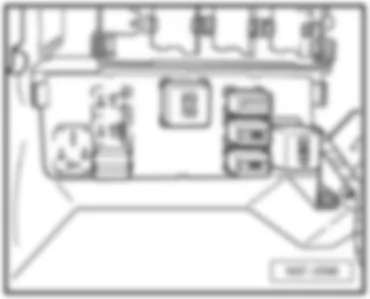
VW JETTA 2010 Relay carrier on left under dash panel
Relay carrier on left under dash panel | 
