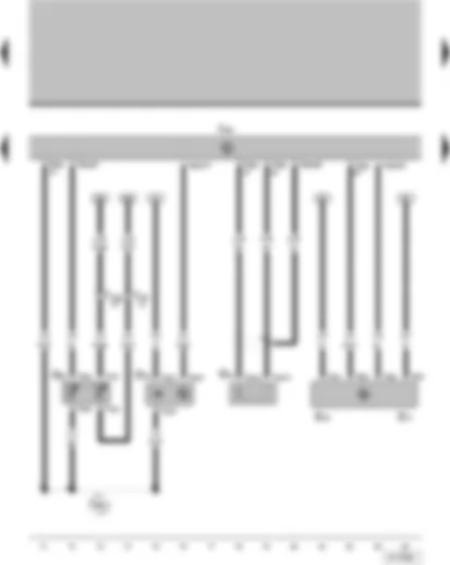
| A | Battery |
| B | Starter |
| C | Alternator |
| C1 | Voltage regulator |
| T1ag | Single pin connector, on starter |
| T2bo | 2-pin connector, on alternator |
| T2v | 2-pin connector, near battery |
| T16c | 16-pin connector, yellow, next to relay plate |
| 1 | Earth strap, battery - body |
| 49 | Earth point, near battery |
| D26 | Positive connection (B+), in alternator wiring harness |
| P1 | Positive connection (30), in fuse holder on battery |
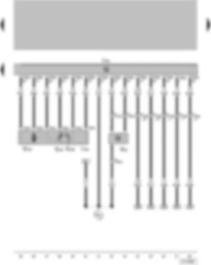
| F4 | Reversing light switch |
| F163 | Thermal switch for air conditioning system shut-off |
| G39 | Lambda probe |
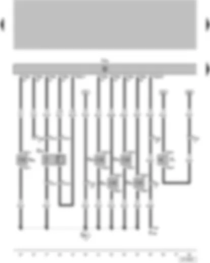
| J623 | Engine control unit |
| N30 | Injector, cylinder 1 |
| N31 | Injector, cylinder 2 |
| N32 | Injector, cylinder 3 |
| N33 | Injector, cylinder 4 |
| N80 | Activated charcoal filter system solenoid valve 1 |
| T1af | Single pin connector, on thermal switch for air conditioning system shut-off |
| T2ar | 2-pin connector, on active charcoal filter system solenoid valve 1 |
| T2ax | 2-pin connector, on reversing light switch |
| T2bd | 2-pin connector, on injector, cylinder 1 |
| T2be | 2-pin connector, on injector, cylinder 2 |
| T2bf | 2-pin connector, on injector, cylinder 3 |
| T2bg | 2-pin connector, on injector, cylinder 4 |
| T4h | 4-pin connector, on lambda probe |
| T8b | 8-pin connector, behind centre dash panel |
| T16f | 16-pin connector, black, behind the glove compartment |
| T16g | 16-pin connector, red, behind the glove compartment |
| T80a | 80-pin connector, on engine control unit |
| E43 | Positive connection (87), in injection system wiring harness |
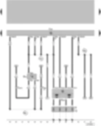
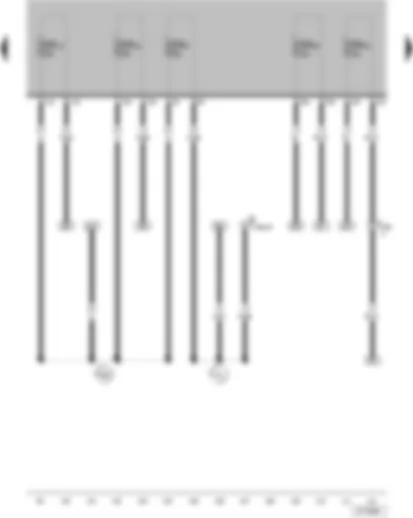
| G22 | Speedometer sender |
| J623 | Engine control unit |
| N152 | Ignition transformer |
| P | Spark plug connector |
| Q | Spark plugs |
| T3g | 3-pin connector, on speedometer sender |
| T4w | 4-pin connector, on ignition transformer |
| T16f | 16-pin connector, black, behind the glove compartment |
| T16g | 16-pin connector, red, behind the glove compartment |
| T80a | 80-pin connector, on engine control unit |
| 331 | Earth connection, in injection system wiring harness |
| E40 | Connection (speedometer sender), in injection system wiring harness |
| E46 | Positive connection 1 (5 Volt), in injection system wiring harness |
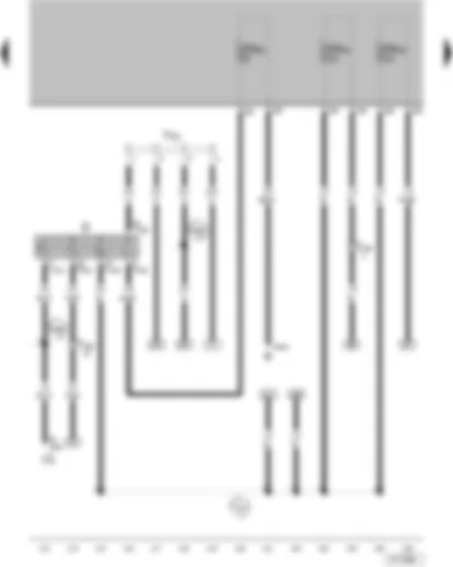
| F36 | Clutch pedal switch |
| G79 | Accelerator position sender |
| G185 | Accelerator position sender 2 |
| J101 | Radiator fan 2nd speed relay |
| J301 | Air conditioning system control unit |
| J362 | Immobilizer control unit |
| J365 | Air conditioning system switch-off relay |
| J623 | Engine control unit |
| T4l | 4-pin connector, on clutch pedal switch |
| T6h | 6-pin connector, in accelerator position sender |
| T8b | 8-pin connector, behind centre dash panel |
| T8c | 8-pin connector, on air conditioning system control unit |
| T8g | 8-pin connector, on immobilizer control unit |
| T8l | 8-pin connector, behind steering column trim |
| T9g | 9-pin connector, on radiator fan 2nd speed relay |
| T9j | 9-pin connector, on air conditioning system switch-off relay |
| T16f | 16-pin connector, black, behind the glove compartment |
| T16g | 16-pin connector, red, behind the glove compartment |
| T80a | 80-pin connector, on engine control unit |
| A100 | Connection 2 (87), in dash panel wiring harness |
| F | Brake light switch |
| F47 | Brake pedal switch |
| F129 | Air conditioning system pressure switch |
| J17 | Fuel pump relay |
| J362 | Immobilizer control unit |
| J623 | Engine control unit |
| T2h | 2-pin connector, behind side trim on rear left, near wheel housing |
| T4m | 4-pin connector, on brake light switch |
| T4o | 4-pin connector, on air conditioning system pressure switch |
| T8g | 8-pin connector, on immobilizer control unit |
| T9b | 9-pin connector, on fuel pump relay |
| T16b | 16-pin connector, red, next to relay plate |
| T16e | 16-pin connector, brown, next to relay plate |
| T16f | 16-pin connector, black, behind the glove compartment |
| T16g | 16-pin connector, red, behind the glove compartment |
| T80a | 80-pin connector, on engine control unit |
| A18 | Connection (54), in dash panel wiring harness |
| A20 | Positive connection (15a), in dash panel wiring harness |
| A193 | Positive connection (87a), in dash panel wiring harness |
| W1 | Positive connection 1 (54), in rear wiring harness |
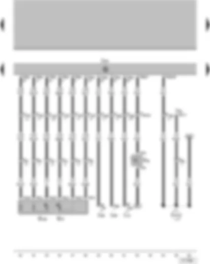
| G40 | Hall sender |
| G42 | Intake air temperature sender |
| G61 | Knock sensor 1 |
| G62 | Coolant temperature sender |
| G71 | Intake manifold pressure sender |
| J623 | Engine control unit |
| T2au | 2-pin connector, on knock sensor 1 |
| T3q | 3-pin connector, on Hall sender |
| T4j | 4-pin connector, on intake air temperature sender |
| T4k | 4-pin connector, on coolant temperature sender |
| T16f | 16-pin connector, black, behind the glove compartment |
| T16g | 16-pin connector, red, behind the glove compartment |
| T80a | 80-pin connector, on engine control unit |
| 339 | Earth connection (sender earth), in injection system wiring harness |
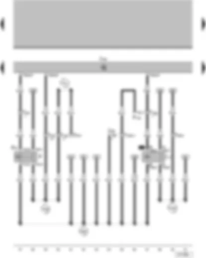
| G28 | Engine speed sender |
| G186 | Throttle valve drive for electric throttle (EPC) |
| G187 | Throttle valve drive angle sender 1 for electric throttle (EPC) |
| G188 | Throttle valve drive angle sender 2 for electric throttle (EPC) |
| J338 | Throttle valve module |
| J623 | Engine control unit |
| T3a | 3-pin connector, on engine speed sender |
| T6x | 6-pin connector, on throttle valve module |
| T16g | 16-pin connector, red, behind the glove compartment |
| T80a | 80-pin connector, on engine control unit |
| 473 | Earth connection 5, in injection system wiring harness |
| D | Ignition/starter switch |
| J59 | X-contact relief relay |
| R | Radio |
| SA23 | Fuse 23 on fuse holder A |
| SA24 | Fuse 24 on fuse holder A |
| SA32 | Fuse 32 on fuse holder A |
| T6a | 6-pin connector, on X-contact relief relay |
| T7c | 7-pin connector, on ignition/starter switch |
| T8h | 8-connector, on radio |
| T16c | 16-pin connector, yellow, next to relay plate |
| T16f | 16-pin connector, black, behind the glove compartment |
| TV2 | Terminal 30 wiring junction |
| A2 | Positive connection (15), in dash panel wiring harness |
| A49 | Connection 1, in dash panel wiring harness |
| A52 | Positive connection 2 (30), in dash panel wiring harness |
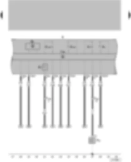
| F22 | Oil pressure switch |
| G1 | Fuel gauge |
| G5 | Rev. counter |
| J285 | Control unit in dash panel insert |
| K | Dash panel insert |
| K2 | Alternator warning lamp |
| K3 | Oil pressure warning lamp |
| K105 | Reserve fuel warning lamp |
| K132 | Electric power control fault lamp |
| T1x | Single pin connector, on oil pressure switch |
| T16b | 16-pin connector, red, next to relay plate |
| T16g | 16-pin connector, red, behind the glove compartment |
| T32a | 32-pin connector, on dash panel insert |
| G | Fuel gauge sender |
| G6 | Fuel system pressurisation pump |
| J209 | Fresh air blower and radiator fan relay |
| SA5 | Fuse 5 on fuse holder A |
| T3m | 3-pin connector, radiator fan on right of radiator |
| T4z | 4-pin connector, on fuel pump |
| T5m | 5-pin connector, on right tail light |
| T9f | 9-pin connector, on fresh air blower and radiator fan relay |
| T16b | 16-pin connector, red, next to relay plate |
| T16e | 16-pin connector, brown, next to relay plate |
| V35 | Right radiator fan |
| 44 | Earth point, lower part of left A-pillar |
| 86 | Earth connection 1, in rear wiring harness |
| 335 | Earth connection 5, in dash panel wiring harness |
| A164 | Positive connection 2 (30a), in dash panel wiring harness |
| W28 | Positive connection 2 (54), in tail light wiring harness |
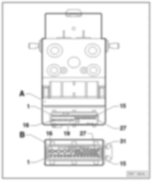
| Designation of connector: | | A - | ABS control unit -J104- | | B - | 31-pin connector, on ABS control unit -T31a- |
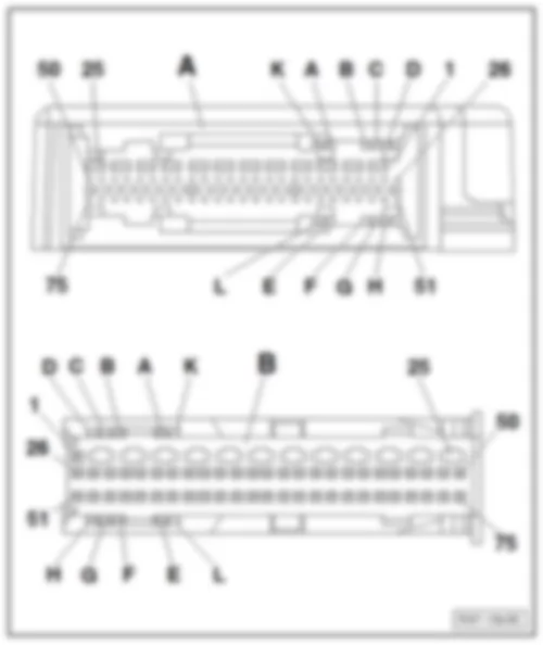
| Airbag control unit -J234- | | | | | Designation of connector: | | A - | Airbag control unit -J234- | | B - | 75-pin connector, on ABS control unit -T75a- |
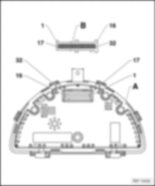
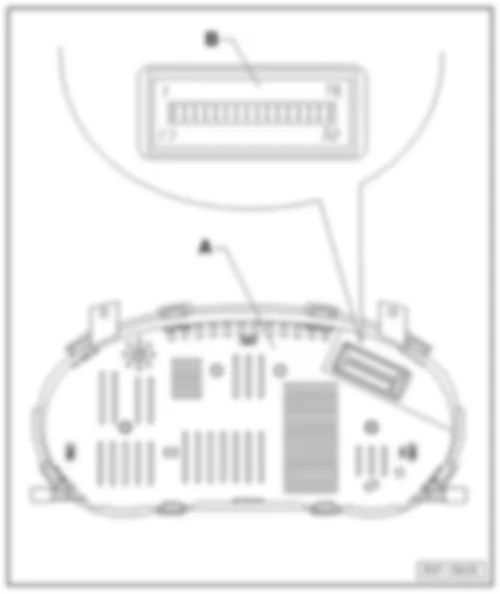
| Control unit with display in dash panel insert -J285- | | | | | Designation of connector: | | A - | Control unit with display in dash panel insert -J285- | | B - | 32-pin connector, on control unit with display in dash panel insert -T32a- | | 8 - | Coolant temperature sender | | 20 - | Immobilizer control unit | | 29 - | Brake system monitoring | | B - | 32-pin connector, on control unit with display in dash panel insert -T32a- | Note | for models with 1.0 l Flex engine, 1.0 l and 1.4 l petrol engines only, from March 2008 | | 4 - | Terminal CAN-Bus high | | 14 - | Brake system monitoring | | 15 - | Immobilizer control unit | | 16 - | Immobilizer control unit |
| Control unit with display in dash panel insert -J285- | Note | for models Generation IV with dash panel Generation III only | | | | | Designation of connector: | | A - | Control unit with display in dash panel insert -J285- | | B - | 32-pin connector, on control unit in dash panel insert -T32a- | | 8 - | Coolant temperature sender | | 16 - | Immobilizer control unit | | 22 - | Coolant shortage indicator sender | | 29 - | Brake system monitoring |
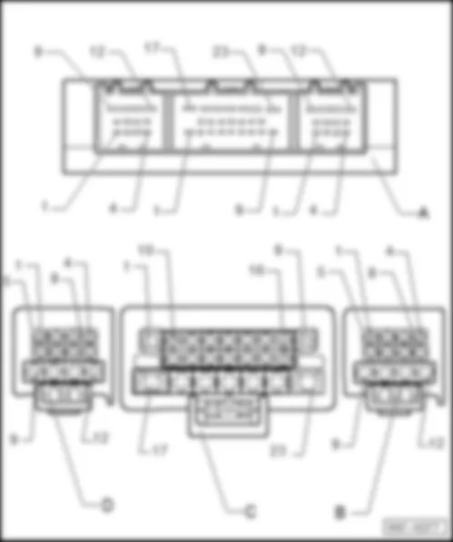
| Convenience system central control unit -J393- | | | | | Designation of connector: | | A - | Convenience system central control unit -J393- | | B - | 12-pin connector, on convenience system central control unit -T12c- | | C - | 23-pin connector, on convenience system central control unit -T23a- | | D - | 12-pin connector, on convenience system central control unit -T12b- |
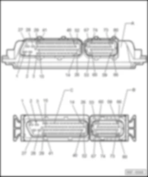
| Engine control unit -J623- | | | | | Designation of connector: | | A - | Engine control unit -J623- | | B/C - | 80-pin connector, on engine control unit -T80a- |
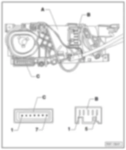
| Air conditioning system control unit -J301- | | | | | Designation of connector: | | A - | Air conditioning system control unit -J301- | | B - | 5-pin connector, on air conditioning system control unit -T5d- | | C - | 7-pin connector, on heater control unit -T7d- |
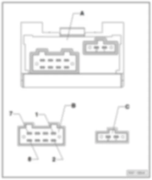
| Immobilizer control unit -J362- | | | | | Designation of connector: | | A - | Immobilizer control unit -J362- | | B - | 8-pin connector, on immobilizer control unit -T8g- | | C - | 2-pin connector, on immobilizer control unit -T2bp- |
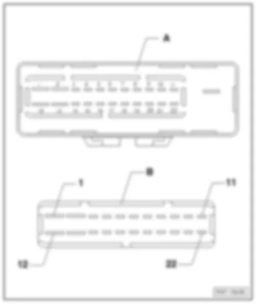
| Alarm system control unit -J85- | | | | | Designation of connector: | | A - | Alarm system control unit -J85- | | B - | 22-pin connector, on alarm system control unit -T22a- |
| | | | | | | | |

