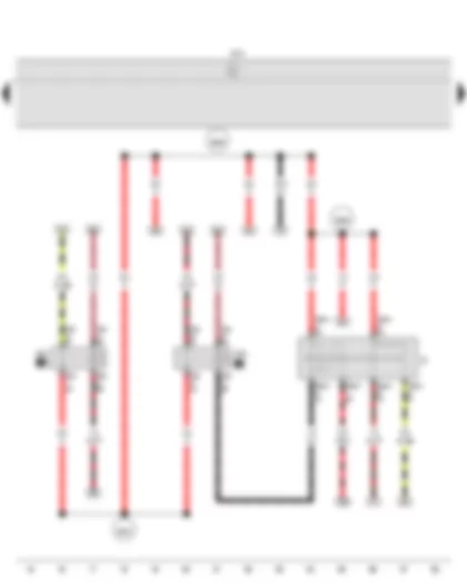
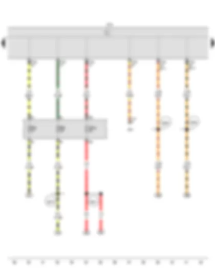
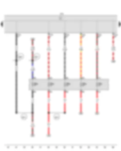
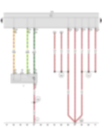
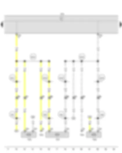
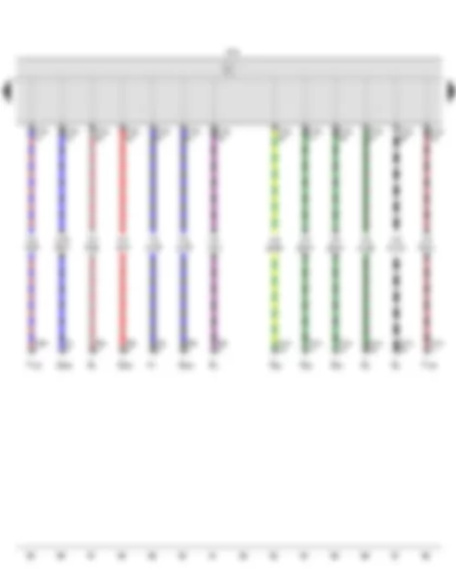
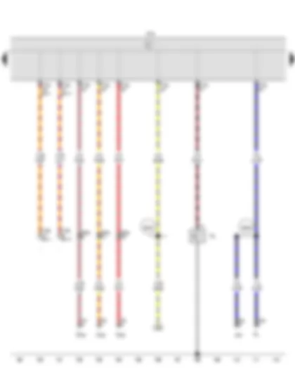
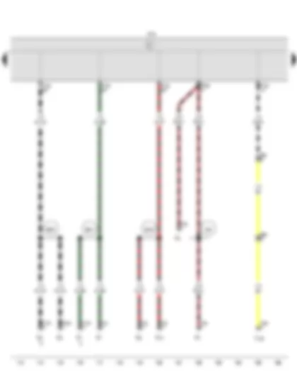
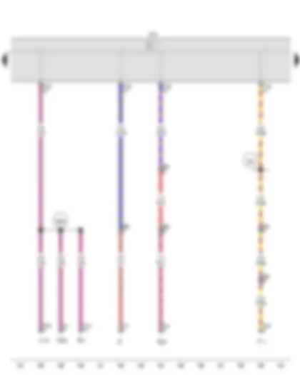
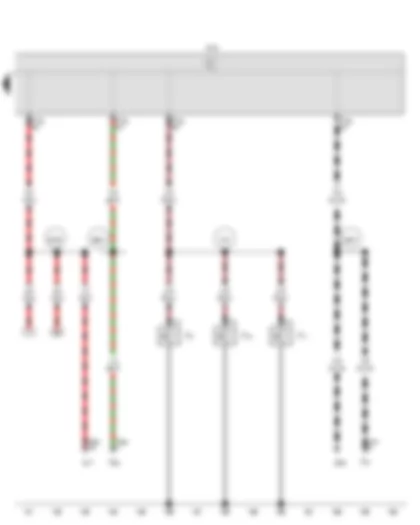
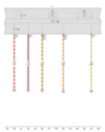
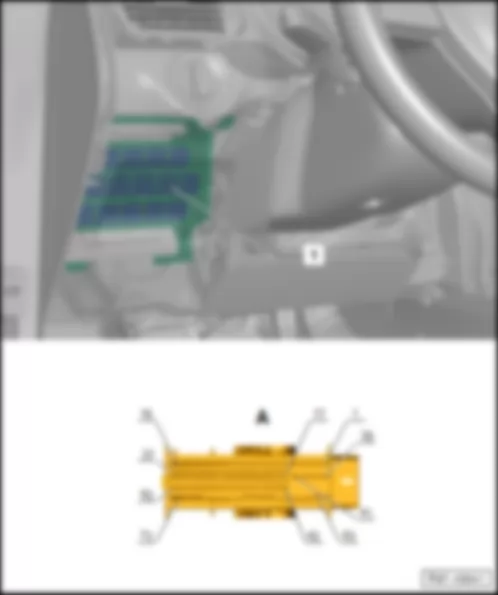
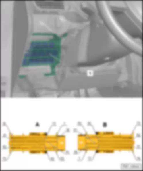
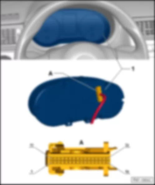
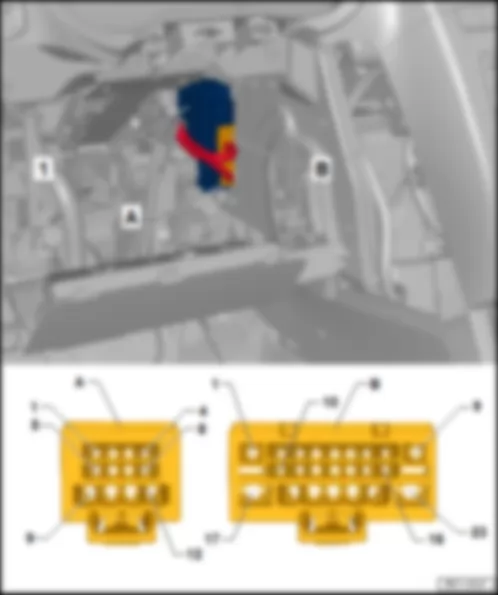
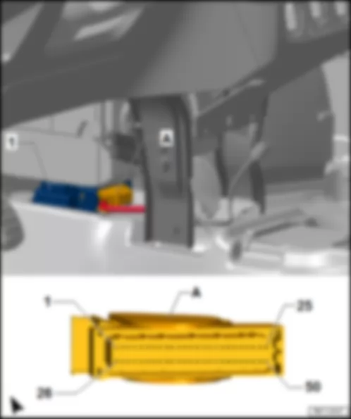
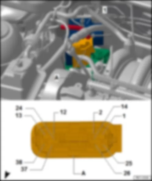
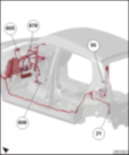
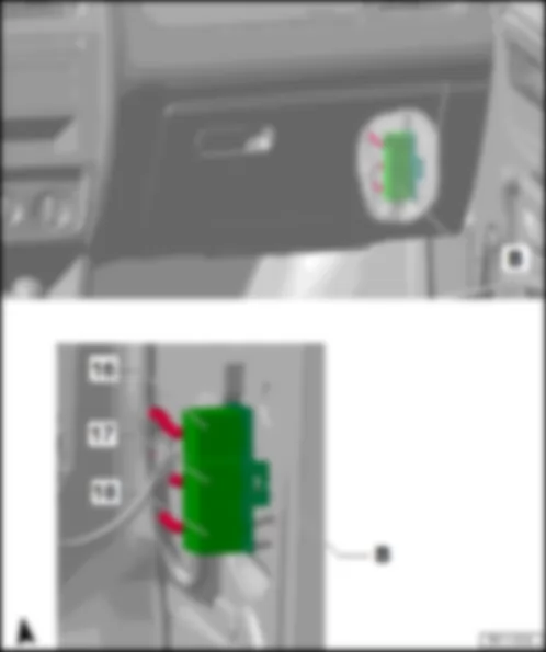
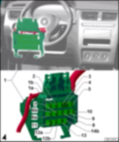
| J519 | Onboard supply control unit |
| T2dh | 2-pin connector |
| T2di | 2-pin connector |
| T2dj | 2-pin connector |
| T4k | 4-pin connector, in front left door |
| T4n | 4-pin connector, in front right door |
| T6j | 6-pin connector |
| T6n | 6-pin connector, in rear right door |
| T6q | 6-pin connector, in rear left door |
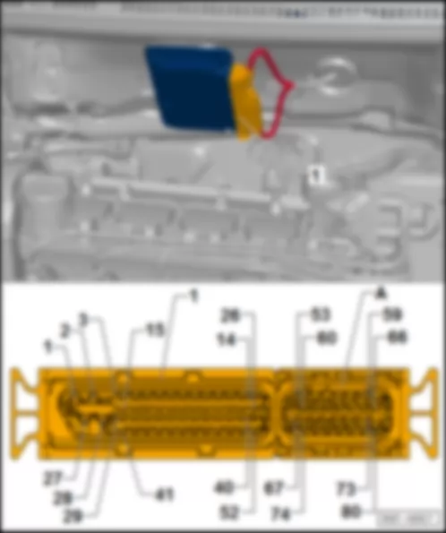
| T73a | 73-pin connector |
| V302 | Driver door power latching motor |
| V303 | Front passenger door power latching motor |
| V307 | Rear left power latching motor |
| V308 | Rear right power latching motor |
| B720 | Connection 1 (central locking), in main wiring harness |
| B721 | Connection 2 (central locking), in main wiring harness |
| B722 | Connection 3 (central locking), in main wiring harness |
| B723 | Connection 4 (central locking), in main wiring harness |
| B724 | Connection (central locking unlocked), in main wiring harness |
| B725 | Connection (central locking locked), in main wiring harness |
| R84 | Connection 1 (central locking), in rear left door wiring harness |
| R85 | Connection 2 (central locking), in rear left door wiring harness |
| R86 | Connection 1 (central locking), in rear right door wiring harness |
| R87 | Connection 2 (central locking), in rear right door wiring harness |
| T73a | - | Function |
| 1 | - | Windscreen wiper motor -V- |
| 2 | - | Windscreen wiper motor -V- |
| 3 | - | Terminal 31 |
| 4 | - | Front interior light -W1- |
| 5 | - | -- |
| 6 | - | -- |
| 7 | - | -- |
| 8 | - | -- |
| 9 | - | Terminal 30, Fuse 40 in fuse holder B -SB40- |
| 10 | - | Rear tailgate unlocking motor -V139- , Central control unit for window control -J1015- |
| 11 | - | Terminal 31 |
| 12 | - | Terminal 30, Fuse 16 in fuse holder A -SA16- |
| 13 | - | -- |
| 14 | - | Terminal 31 |
| 15 | - | Rear right central locking system motor -V308- , Driver door central locking system motor -V302- , Rear left central locking system motor -V307- |
| 16 | - | Passenger door central locking system motor -V303- , Rear right central locking system motor -V308- |
| 17 | - | -- |
| 18 | - | -- |
| 19 | - | -- |
| 20 | - | Central control unit for window control -J1015- , Alarm system ultrasound sensor -G209- , Rear window wiper motor -E34- |
| 21 | - | Rear window heating system switch -E230- |
| 22 | - | -- |
| 23 | - | -- |
| 24 | - | Alarm horn relay -J641- |
| 25 | - | Warning light switch -E3- |
| 26 | - | Instrument cluster -K- |
| 27 | - | Diagnosis terminal - CAN High |
| 28 | - | Diagnosis terminal - CAN Low |
| 29 | - | CAN-Bus, High |
| 30 | - | CAN-Bus, Low |
| 31 | - | Front lid / engine lid contact switch for the alarm system -F120- |
| 32 | - | Int. locking switch, driver side -E150- |
| 33 | - | Alarm system ultrasound sensor -G209- |
| 34 | - | Rear tailgate unlocking switch -E165- |
| 35 | - | Driver door central locking system motor -V302- |
| 36 | - | Driver door central locking system motor -V302- |
| 37 | - | Central control unit for window control -J1015- , Rear tailgate unlocking motor -V139- |
| 38 | - | Terminal 31 |
| 39 | - | -- |
| 40 | - | -- |
| 41 | - | -- |
| 42 | - | Terminal 30, Fuse 9 (30) of the battery fuse holder -S267- |
| 43 | - | Terminal31 |
| 44 | - | Windscreen wiper motor -V- |
| 45 | - | Engine control unit -J623- , Brake pedal switch -F47- |
| 46 | - | Windscreen wiper delay relay switch (intermittent operation) -E22- |
| 47 | - | Windscreen wiper delay relay switch (intermittent operation) -E22- |
| 48 | - | External side mirror folding control unit -J351- , Reverse gear light switch -F4- |
| 49 | - | Instrument cluster -K- |
| 50 | - | Generator (Alternator) -C- , Voltage regulator -C1- |
| 51 | | Terminal 15, Fuse 38 in fuse holder B -SB38- , Relief relay of terminal 15 -J404- |
| 52 | - | Terminal 50, Automatic gearbox control unit -J217- |
| 53 | - | Terminal S, Fuse 2 in fuse holder A -SA2- |
| 54 | - | Rear window wiper motor -V12- , Rear window and windscreen washer pump -V59- |
| 55 | - | Rear window heating system switch -E230- |
| 56 | - | Windscreen wiper delay relay switch (intermittent operation) -E22- |
| 57 | - | Turn light/flashing light switch -E2- |
| 58 | - | Turn light/flashing light switch -E2- |
| 59 | - | Contact of the airbag coil and return spring with slip ring -F138- |
| 60 | - | Warning light switch -E3- |
| 61 | - | Driver door contact switch -F2- |
| 62 | - | Passenger door contact switch -F3- , Rear left door contact switch -F10- , Rear right door contact switch -F11- |
| 63 | - | Terminal 30, Fuse 29 in fuse holder B -SB29- |
| 64 | - | Front right turn signal lamp -M7- |
| 65 | - | Fuse 25 in fuse holder B -SB25- |
| 66 | - | Front left turn signal lamp -M5- |
| 67 | - | Horn and double horn -H1- |
| 68 | - | Fuse 41 in fuse holder B -SB41- |
| 69 | - | Left brake light lamp -M9- , Right brake light lamp -M10- |
| 70 | - | -- |
| 71 | - | -- |
| 72 | - | Rear window defogger -Z1- |
| 73 | - | Fuse 6 of fuse holder A -SA6- |
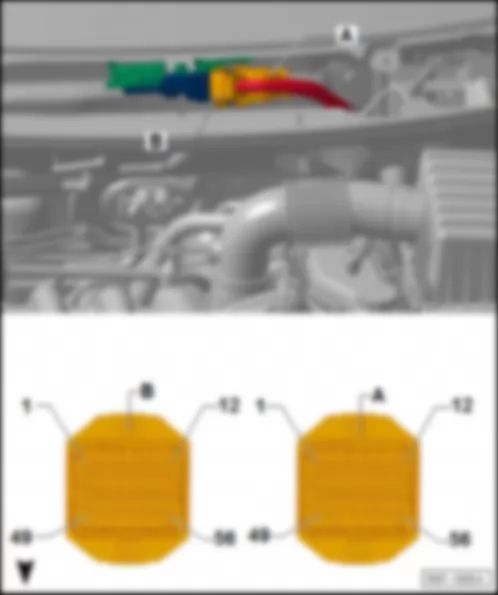
| T73b | - | Function | - | T73c | - | Function |
| 1 | - | Headlights relay -J12- | - | 1 | - | -- |
| 2 | - | Left low beam lamp -M29- , Sealed left headlight double-filament lamp -L1- | - | 2 | - | Sealed right headlight double-filament lamp -L2- , Right low beam lamp -M31- |
| 3 | - | -- | - | 3 | - | -- |
| 4 | - | Internal lighting, Front internal light -W1- | - | 4 | - | Instrument cluster -K- |
| 5 | - | -- | - | 5 | - | -- |
| 6 | - | Fog light lamp -L20- , Fog lights switch -E23- , Instrument cluster -K- | - | 6 | - | -- |
| 7 | - | Fog lights switch -E23- | - | 7 | - | License plate light -X- |
| 8 | - | -- | - | 8 | - | -- |
| 9 | - | -- | - | 9 | - | Left fog light and long-range headlight lamp -M94- , Right fog light lamp -L23- |
| 10 | - | Rear tailgate unlocking motor -V139- , Central control unit for window control -J1015- , Spare wheel unlocking motor -V340- | - | 10 | - | Right fog light and long-range headlight lamp -M95- , Left fog light lamp -L22- |
| 11 | - | Passenger door central locking system motor -V303- , Driver door central locking system motor -V302- , Rear left central locking system motor -V307- , Rear right central locking system motor -V308- | - | 11 | - | Terminal 30, Fuse 1 in fuse holder A -SA1- |
| 12 | - | Driver door central locking system motor -V302- | - | 12 | - | -- |
| 13 | - | -- | - | 13 | - | Terminal 30, Fuse 25 in fuse holder B -SB25- |
| 14 | - | Terminal 31 | - | 14 | - | Front left turn signal lamp -M5- , Rear left turn signal lamp -M6- |
| 15 | - | Passenger door central locking system motor -V303- , Driver door central locking system motor -V302- , Rear left central locking system motor -V307- , Rear right central locking system motor -V308- | - | 15 | - | Front right turn signal lamp -M7- , Rear right turn signal lamp -M8- |
| 16 | - | Terminal 30, Fuse 16 in fuse holder A -SA16- | - | 16 | - | Left brake light lamp -M9- , Right brake light lamp -M10- , Automatic gearbox control unit -J217- |
| 17 | - | Driver door central locking system motor -V302- | - | 17 | - | Central control unit for window control -J1015- , Alarm system ultrasound sensor -G209- , Rear window wiper motor -E34- |
| 18 | - | Driver door central locking system motor -V302- | - | 18 | - | CAN-Bus, Low |
| 19 | - | Driver door contact switch -F2- | - | 19 | - | CAN-Bus, High |
| 20 | - | Passenger door contact switch -F3- | - | 20 | - | Radio -R- |
| 21 | - | Driver door central locking system motor -V302- | - | 21 | - | Radio -R- |
| 22 | - | Driver door central locking system motor -V302- | - | 22 | - | Diagnosis terminal, CAN-Low |
| 23 | - | Rear tailgate unlocking switch -E165- , Spare wheel unlocking switch -E405- , Spare wheel unlocking support switch -E727- | - | 23 | - | Diagnosis terminal, CAN-High |
| 24 | - | Driver door central locking system motor -V302- | - | 24 | - | Right alarm ultrasound sensor -G171- , Alarm system ultrasound sensor -G209- , Rain sensor and photodetector -G397- |
| 25 | - | Int. locking switch, driver side -E150- | - | 25 | - | -- |
| 26 | - | Rear right door contact switch -F11- | - | 26 | - | -- |
| 27 | - | Front lid / engine lid contact switch for the alarm system -F120- | - | 27 | - | Windscreen wiper delay relay switch (intermittent operation) -E22- |
| 28 | - | Warning light switch -E3- | - | 28 | - | -- |
| 29 | - | Contact of the airbag coil and return spring with slip ring -F138- | - | 29 | - | -- |
| 30 | - | Central control unit for window control -J1015- , Rear tailgate unlocking motor -V139- | - | 30 | - | Left alarm ultrasound sensor -G170- |
| 31 | - | -- | - | 31 | - | Rear window heating system switch -E230- |
| 32 | - | Turn light/flashing light switch -E2- | - | 32 | - | Windscreen wiper motor -V- |
| 33 | - | Turn light/flashing light switch -E2- | - | 33 | - | -- |
| 34 | - | Rear left door contact switch -F10- | - | 34 | - | Instrument cluster -K- , Light switch illumination lamp -L9- , |
| 35 | - | Sunroof movement control unit -J245- | - | 35 | - | -- |
| 36 | - | -- | - | 36 | - | -- |
| 37 | - | Light switch -E1- | - | 37 | - | -- |
| 38 | - | -- | - | 38 | - | Terminal 31 |
| 39 | - | Terminal 31 | - | 39 | - | Terminal 30, Fuse 40 in fuse holder B -SB40- |
| 40 | - | Front right side lamp -M3- , Rear right lamp -M2- | - | 40 | - | Terminal 31 |
| 41 | - | Front left side lamp -M1- , Rear left lamp -M4- | - | 41 | - | -- |
| 42 | - | Terminal S, Fuse 2 in fuse holder A -SA2- | - | 42 | - | -- |
| 43 | - | Engine control unit -J623- , Brake pedal switch -F47- | - | 43 | - | Light switch -E1- |
| 44 | - | Terminal 15, Fuse 38 in fuse holder B -SB38- , Relief relay of terminal 15 -J404- | - | 44 | - | -- |
| 45 | - | Light switch -E1- | - | 45 | - | -- |
| 46 | - | -- | - | 46 | - | -- |
| 47 | - | -- | - | 47 | - | -- |
| 48 | - | Sunroof movement control unit -J245- | - | 48 | - | External side mirror folding control unit -J351- , Reverse gear light switch -F4- , Left reverse gear light lamp -M16- , Right reverse gear light lamp -M17- |
| 49 | - | -- | - | 49 | - | Generator (Alternator) -C- , Voltage regulator -C1- |
| 50 | - | -- | - | 50 | - | Automatic gearbox control unit -J217- , Starter -B- , Ignition switch -D- , Engine control unit -J623- |
| 51 | - | -- | - | 51 | - | Ignition switch -D- , Relief relay for contact X -J59- , Relief relay 2 of contact X -J339- |
| 52 | - | -- | - | 52 | - | Light switch -E1- |
| 53 | - | Alarm horn relay -J641- | - | 53 | - | Windscreen wiper delay relay switch (intermittent operation) -E22- |
| 54 | - | -- | - | 54 | - | CAN-Bus, High |
| 55 | - | -- | - | 55 | - | -- |
| 56 | - | Warning light switch -E3- | - | 56 | - | -- |
| 57 | - | Left alarm ultrasound sensor -G170- | - | 57 | - | CAN-Bus, Low |
| 58 | - | Instrument cluster -K- | - | 58 | - | -- |
| 59 | - | -- | - | 59 | - | Terminal 30, Fuse 9 (30) of the battery fuse holder -S267- |
| 60 | - | Rear window heating system switch -E230- | - | 60 | - | Terminal 31 |
| 61 | - | -- | - | 61 | - | Rear window wiper motor -V12- , Rear window and windscreen washer pump -V59- , Windscreen wiper delay relay control -E38- |
| 62 | - | Relay 2 for long-range headlights -J1062- , Fog lights relay -J5- , Turn light/flashing light switch -E2- | - | 62 | - | Windscreen wiper delay relay switch (intermittent operation) -E22- |
| 63 | - | Terminal 30, Fuse 36 in fuse holder B -SB36- | - | 63 | - | Rear window defogger -Z1- |
| 64 | - | -- | - | 64 | - | -- |
| 65 | - | Internal lighting, Rear left reading light -W11- , Rear right reading lamp -W12- | - | 65 | - | -- |
| 66 | - | Internal lighting, Alarm system ultrasound sensor -G209- , Right alarm ultrasound sensor -G171- , Rain sensor and photodetector -G397- | - | 66 | - | -- |
| 67 | - | -- | - | 67 | - | Terminal 30, Fuse 6 in fuse holder A -SA6- |
| 68 | - | Terminal 30, Fuse 29 in fuse holder B -SB29- | - | 68 | - | Terminal 30, Fuse 47 in fuse holder B -SB47- |
| 69 | - | Windscreen wiper motor -V- | - | 69 | - | -- |
| 70 | - | Terminal 31 | - | 70 | - | -- |
| 71 | - | Windscreen wiper motor -V- | - | 71 | - | -- |
| 72 | - | Horn and double horn -H1- | - | 72 | - | -- |
| 73 | - | Terminal 30, Fuse 41 in fuse holder B -SB41- | - | 73 | - | -- |
| T12g | - | Function | - | T23b | - | Function |
| 1 | - | Rear window control blocking switch -E39- | - | 1 | - | Terminal 31 |
| 2 | - | Rear window control blocking switch -E39- | - | 2 | - | Onboard network control unit -J519- |
| 3 | - | -- | - | 3 | - | -- |
| 4 | - | Rear window control blocking switch -E39- | - | 4 | - | -- |
| 5 | - | Rear left window control switch, driver side -E53- | - | 5 | - | -- |
| 6 | - | Rear left window control switch -E52- | - | 6 | - | -- |
| 7 | - | Rear left window control switch, driver side -E53- | - | 7 | - | Front right window control switch, driver side -E81- |
| 8 | - | Rear right window control switch -E54- | - | 8 | - | -- |
| 9 | - | Rear left window control motor -V26- | - | 9 | - | Terminal 31 |
| 10 | - | Rear left window control motor -V26- | - | 10 | - | -- |
| 11 | - | Rear right window control motor -V27- | - | 11 | - | -- |
| 12 | - | Rear right window control motor -V27- | - | 12 | - | Diagnosis terminal - K |
| -- | - | -- | - | 13 | - | -- |
| | - | -- | - | 14 | - | -- |
| -- | - | -- | - | 15 | - | Front right window control switch, driver side -E81- |
| -- | - | -- | - | 16 | - | Passenger door window control switch -E107- |
| -- | - | -- | - | 17 | - | -- |
| -- | - | -- | - | 18 | - | -- |
| -- | - | -- | - | 19 | - | Driver window control motor -V147- |
| -- | - | -- | - | 20 | - | Driver window control motor -V147- |
| -- | - | -- | - | 21 | - | Passenger window activation motor -V148- |
| -- | - | -- | - | 22 | - | Passenger window activation motor -V148- |
| -- | - | -- | - | 23 | - | Terminal 30, Fuse 22 in fuse holder A -SA22- |

