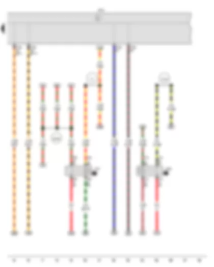
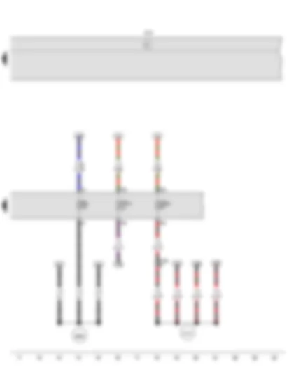
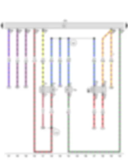
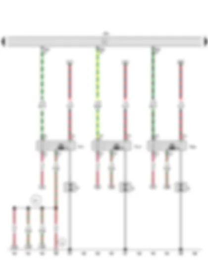
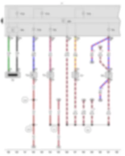
Wiring Diagram VW UP 2016 - Battery - Starter - Alternator - Voltage regulator - Onboard supply control unit
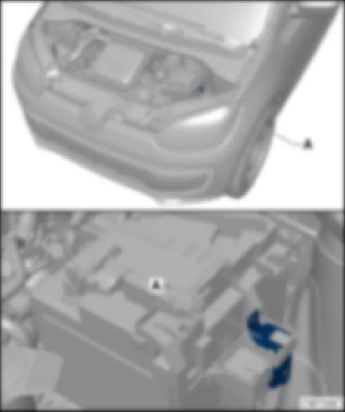
| A | Battery |
| B | Starter |
| C | Alternator |
| C1 | Voltage regulator |
| J519 | Onboard supply control unit |
| S162 | Fuse 1 (30), in battery fuse holder |
| S164 | Fuse 3 (30), in battery fuse holder |
| S176 | Fuse 4 (30), in battery fuse holder |
| S267 | Fuse 9 (30), in battery fuse holder |
| S268 | Fuse 10 (30), in battery fuse holder |
| S271 | Fuse 13 (30), in battery fuse holder |
| T1j | Single connector |
| T2ar | 2-pin connector |
| T4f | 4-pin connector, on left in engine compartment |
| T73a | 73-pin connector |
| 507 | Threaded connection (30), on battery fuse holder |
| * | Only models with onboard supply control unit BFM |
| *2 | Only models with onboard supply control unit BCM |
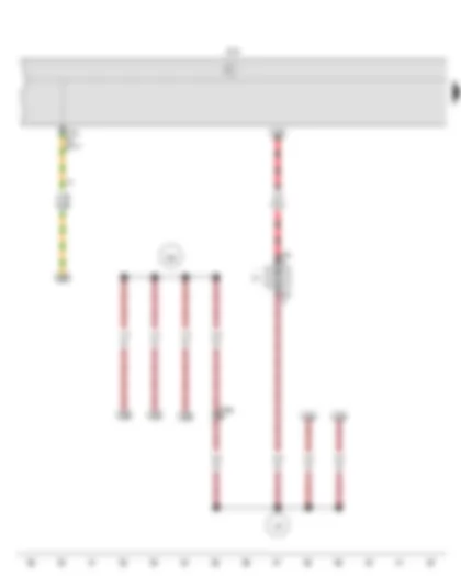
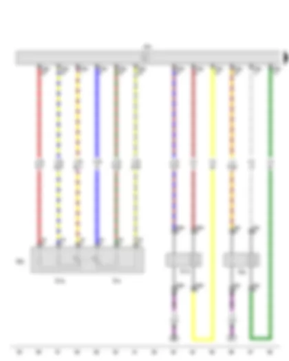
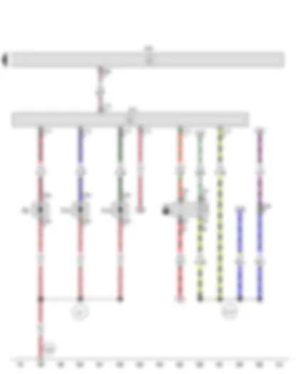
Wiring Diagram VW UP 2016 - Terminal 15 relief relay - Onboard supply control unit - Voltage supply relay 1
| J404 | Terminal 15 relief relay |
| J519 | Onboard supply control unit |
| J701 | Voltage supply relay 1 |
| T7c | 7-pin connector |
| T9n | 9-pin connector |
| T73a | 73-pin connector |
| A1 | Positive connection (30a), in dash panel wiring harness |
| A104 | Positive connection 2 (15), in dash panel wiring harness |
| B146 | Positive connection 1 (87), in interior wiring harness |
| * | Only models with onboard supply control unit BFM |
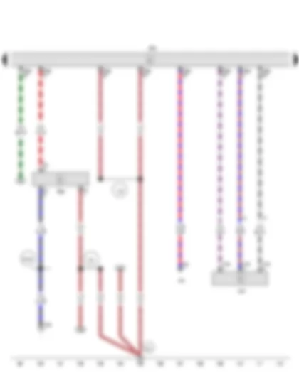
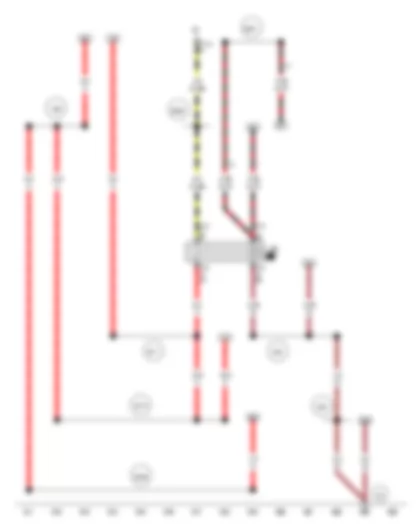
Wiring Diagram VW UP 2016 - Onboard supply control unit - Radiator fan
| J519 | Onboard supply control unit |
| T3b | 3-pin connector |
| T14a | 14-pin connector, on left in engine compartment |
| T73c | 73-pin connector |
| V7 | Radiator fan |
| 167 | Earth connection 4, in engine compartment wiring harness |
| 306 | Earth connection (ignition coils), in engine prewiring harness |
| * | Only models with no air conditioning system |
| *2 | Only models with onboard supply control unit BCM |
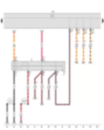
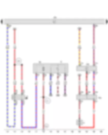
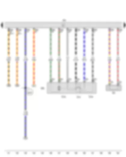
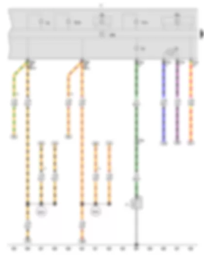
Wiring Diagram VW UP 2016 - Ignition/starter switch - Onboard supply control unit
| D | Ignition/starter switch |
| J519 | Onboard supply control unit |
| T7a | 7-pin connector |
| T73b | 73-pin connector |
| T73c | 73-pin connector |
| A15 | Positive connection (15), in instrument wiring harness |
| B276 | Positive connection (50), in main wiring harness |
| * | Only models with onboard supply control unit BFM |
| *2 | Only models with onboard supply control unit BCM |
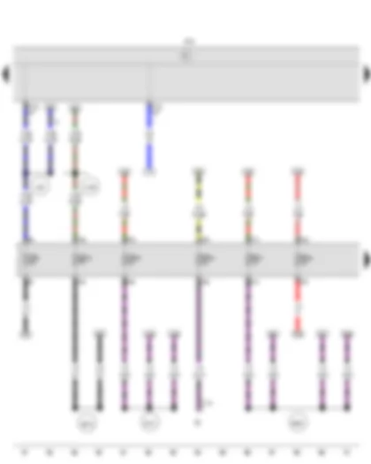
Wiring Diagram VW UP 2016 - Onboard supply control unit
| E1 | Light switch |
| J519 | Onboard supply control unit |
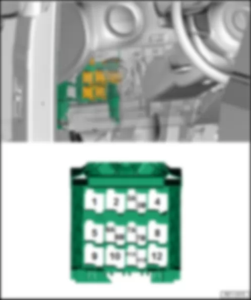
| SA5 | Fuse 5 in fuse holder A |
| SA16 | Fuse 16 in fuse holder A |
| SA31 | Fuse 31 in fuse holder A |
| SA40 | Fuse 40 in fuse holder A |
| SA44 | Fuse 44 in fuse holder A |
| SA45 | Fuse 45 in fuse holder A |
| T17a | 17-pin connector |
| T73b | 73-pin connector |
| T73c | 73-pin connector |
| A20 | Positive connection (15a), in dash panel wiring harness |
| A192 | Positive connection 3 (15a) in dash panel wiring harness |
| B147 | Positive connection 2 (87), in interior wiring harness |
| B273 | Positive connection (15), in main wiring harness |
| B350 | Positive connection 1 (87a) in main wiring harness |
| * | Only models with onboard supply control unit BCM |
| *2 | Only models with onboard supply control unit BFM |
Wiring Diagram VW UP 2016 - Onboard supply control unit
| J519 | Onboard supply control unit |
| SA1 | Fuse 1 in fuse holder A |
| SA19 | Fuse 19 in fuse holder A |
| SA42 | Fuse 42 in fuse holder A |
| T14a | 14-pin connector, on left in engine compartment |
| B626 | Positive connection 2 (15), in main wiring harness |
| D101 | Connection 1 in engine compartment wiring harness |
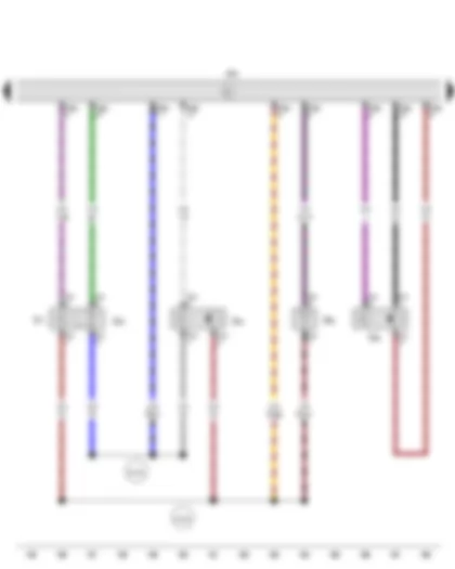
Wiring Diagram VW UP 2016 - Accelerator pedal module - Lambda probe - Accelerator position sender - Lambda probe after catalytic converter - Accelerator position sender 2 - Engine control unit
| GX2 | Accelerator pedal module |
| G39 | Lambda probe |
| G79 | Accelerator position sender |
| G130 | Lambda probe after catalytic converter |
| G185 | Accelerator position sender 2 |
| J623 | Engine control unit |
| T4ah | 4-pin connector |
| T4o | 4-pin connector |
| T6f | 6-pin connector |
| T56a | 56-pin connector |
Wiring Diagram VW UP 2016 - High-pressure sender - Air conditioning system control unit - Engine control unit
| G65 | High-pressure sender |
| J32 | Air conditioning system relay |
| J301 | Air conditioning system control unit |
| J623 | Engine control unit |
| T3j | 3-pin connector |
| T9k | 9-pin connector |
| T16a | 16-pin connector |
| T16h | 16-pin connector |
| T56a | 56-pin connector |
| 85 | Earth connection 1, in engine compartment wiring harness |
| 132 | Earth connection 3, in engine compartment wiring harness |
| B135 | Connection 1 (15a), in interior wiring harness |
| * | Diagnostic connection |
| *2 | Up to November 2014 |
Wiring Diagram VW UP 2016 - Fuel gauge sender - Fuel system pressurisation pump - Fuel pump relay - Radiator fan control unit - Engine control unit - Radiator fan series resistor - Radiator fan
| G | Fuel gauge sender |
| G6 | Fuel system pressurisation pump |
| J17 | Fuel pump relay |
| J293 | Radiator fan control unit |
| J623 | Engine control unit |
| N39 | Radiator fan series resistor |
| T2df | 2-pin connector |
| T3ae | 3-pin connector |
| T5a | 5-pin connector |
| T5j | 5-pin connector |
| T10c | 10-pin connector |
| T56a | 56-pin connector |
| V7 | Radiator fan |
| 271 | Earth connection 3, in front wiring harness |
| A42 | Connection (fuel gauge), in dash panel wiring harness |
| * | Only models with air conditioning system |
Wiring Diagram VW UP 2016 - Brake light switch - Clutch pedal switch - Radiator fan relay - Engine control unit
| F | Brake light switch |
| F36 | Clutch pedal switch |
| J26 | Radiator fan relay |
| J623 | Engine control unit |
| T4l | 4-pin connector |
| T4m | 4-pin connector |
| T5d | 5-pin connector |
| T56a | 56-pin connector |
| A154 | Connection (brake pedal switch), in dash panel wiring harness |
| E30 | Connection (87a), in engine wiring harness |
| * | Only models with no air conditioning system |
| *2 | Only models with air conditioning system |
Wiring Diagram VW UP 2016 - Throttle valve module - Knock sensor 1 - Throttle valve drive for electric throttle - Throttle valve drive angle sender 1 for electric throttle - Throttle valve drive angle sender 2 for electric throttle - Engine control unit
| GX3 | Throttle valve module |
| G61 | Knock sensor 1 |
| G186 | Throttle valve drive for electric throttle |
| G187 | Throttle valve drive angle sender 1 for electric throttle |
| G188 | Throttle valve drive angle sender 2 for electric throttle |
| J623 | Engine control unit |
| T2g | 2-pin connector |
| T6m | 6-pin connector |
| T56a | 56-pin connector |
| T56b | 56-pin connector |
| B278 | Positive connection 2 (15a) in main wiring harness |
Wiring Diagram VW UP 2016 - Engine speed sender - Hall sender - Intake air temperature sender - Coolant temperature sender - Intake manifold pressure sender - Engine control unit
| G28 | Engine speed sender |
| G40 | Hall sender |
| G42 | Intake air temperature sender |
| G62 | Coolant temperature sender |
| G71 | Intake manifold pressure sender |
| J623 | Engine control unit |
| T2h | 2-pin connector |
| T3m | 3-pin connector |
| T3n | 3-pin connector |
| T4h | 4-pin connector |
| T56b | 56-pin connector |
| D102 | Connection 2 in engine compartment wiring harness |
| D103 | Connection 3 in engine compartment wiring harness |
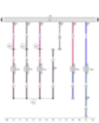
Wiring Diagram VW UP 2016 - Engine control unit - Injector - cylinder 1 - Injector - cylinder 2 - Injector - cylinder 3 - Activated charcoal filter solenoid valve 1 - Camshaft control valve 1
| J623 | Engine control unit |
| N30 | Injector, cylinder 1 |
| N31 | Injector, cylinder 2 |
| N32 | Injector, cylinder 3 |
| N80 | Activated charcoal filter solenoid valve 1 |
| N205 | Camshaft control valve 1 |
| T2i | 2-pin connector |
| T2l | 2-pin connector |
| T2q | 2-pin connector |
| T2t | 2-pin connector |
| T2v | 2-pin connector |
| T14a | 14-pin connector, on left in engine compartment |
| T56b | 56-pin connector |
| D95 | Connection (injectors), in engine compartment wiring harness |
| E56 | Connection 1, in injection system wiring harness |
| E57 | Connection 2, in injection system wiring harness |
| E58 | Connection 3, in injection system wiring harness |
Wiring Diagram VW UP 2016 - Engine control unit - Ignition coil 1 with output stage - Ignition coil 2 with output stage - Ignition coil 3 with output stage - Spark plugs
| J623 | Engine control unit |
| N70 | Ignition coil 1 with output stage |
| N127 | Ignition coil 2 with output stage |
| N291 | Ignition coil 3 with output stage |
| Q | Spark plugs |
| T1vela | Single connector |
| T4j | 4-pin connector |
| T4k | 4-pin connector |
| T4p | 4-pin connector |
| T56b | 56-pin connector |
| 201 | Earth connection 5, in engine compartment wiring harness |
Wiring Diagram VW UP 2016 - Glow plug relay - Glow plug activation control unit - Engine control unit - Fuel pre-heating heater element - Fuel preheating element 2 - Fuel preheating element 3
| J52 | Glow plug relay |
| J370 | Glow plug activation control unit |
| J623 | Engine control unit |
| T2aa | 2-pin connector |
| T2ab | 2-pin connector |
| T2ac | 2-pin connector |
| T5n | 5-pin connector |
| T11a | 11-pin connector |
| T14a | 14-pin connector, on left in engine compartment |
| T56b | 56-pin connector |
| Z66 | Fuel pre-heating heater element |
| Z108 | Fuel preheating element 2 |
| Z109 | Fuel preheating element 3 |
| 331 | Earth connection, in injection system wiring harness |
| D107 | Connection 5 in engine compartment wiring harness |
Wiring Diagram VW UP 2016 - X-contact relief relay
| E1 | Light switch |
| J59 | X-contact relief relay |
| T7b | 7-pin connector |
| T17a | 17-pin connector |
| 238 | Earth connection 1, in interior wiring harness |
| 249 | Earth connection 2, in interior wiring harness |
| A56 | Positive connection 2 (30), in dash panel wiring harness |
| B169 | Positive connection 1 (30), in interior wiring harness |
| B170 | Positive connection 2 (30), in interior wiring harness |
| B171 | Positive connection 3 (30), in interior wiring harness |
| B346 | Connection 1 (75), in main wiring harness |
| B347 | Connection 2 (75), in main wiring harness |
| * | Only models with onboard supply control unit BFM |
| *2 | Only models with onboard supply control unit BCM |
Wiring Diagram VW UP 2016 - Oil pressure switch - Fuel gauge - Rev. counter - Speedometer - Control unit in dash panel insert - Dash panel insert - Alternator warning lamp - Oil pressure warning lamp - Malfunction warning lamp - Electrohydraulic power steering warning lamp
| F1 | Oil pressure switch |
| G1 | Fuel gauge |
| G5 | Rev. counter |
| G21 | Speedometer |
| J285 | Control unit in dash panel insert |
| K | Dash panel insert |
| K2 | Alternator warning lamp |
| K3 | Oil pressure warning lamp |
| K121 | Malfunction warning lamp |
| K279 | Electrohydraulic power steering warning lamp |
| T1d | Single connector |
| T14a | 14-pin connector, on left in engine compartment |
| T32a | 32-pin connector |
| B383 | Connection 1 (powertrain CAN bus, high), in main wiring harness |
| B390 | Connection 1 (powertrain CAN bus, low), in main wiring harness |
| * | Only models with onboard supply control unit BFM |
| *2 | Only models with onboard supply control unit BCM |
Wiring Diagram VW UP 2016 - Immobiliser reader coil - Brake fluid level warning contact - Parking brake contact switch - Ambient temperature sensor - Coolant shortage indicator sender - Control unit in dash panel insert - Immobiliser control unit - Dash panel insert - Handbrake warning lamp - Earth connection 4 - in front wiring harness
| D2 | Immobiliser reader coil |
| F34 | Brake fluid level warning contact |
| F321 | Parking brake contact switch |
| G17 | Ambient temperature sensor |
| G32 | Coolant shortage indicator sender |
| J285 | Control unit in dash panel insert |
| J362 | Immobiliser control unit |
| K | Dash panel insert |
| K33 | Brake fluid level warning lamp |
| K43 | Coolant temperature warning lamp (too cold) |
| K105 | Reserve fuel warning lamp |
| K132 | Electronic power control fault lamp |
| K139 | Handbrake warning lamp |
| K143 | Cold start device warning lamp |
| T2ai | 2-pin connector |
| T2b | 2-pin connector |
| T2dv | 2-pin connector |
| T2j | 2-pin connector |
| T2s | 2-pin connector |
| T32a | 32-pin connector |
| 104 | Earth connection in front right wiring harness - sensor earth - |
| 131 | Earth connection 2, in engine compartment wiring harness |
| 272 | Earth connection 4, in front wiring harness |
| 279 | Earth connection 5, in interior wiring harness |
| * | Up to November 2014 |
| *2 | From November 2014 |
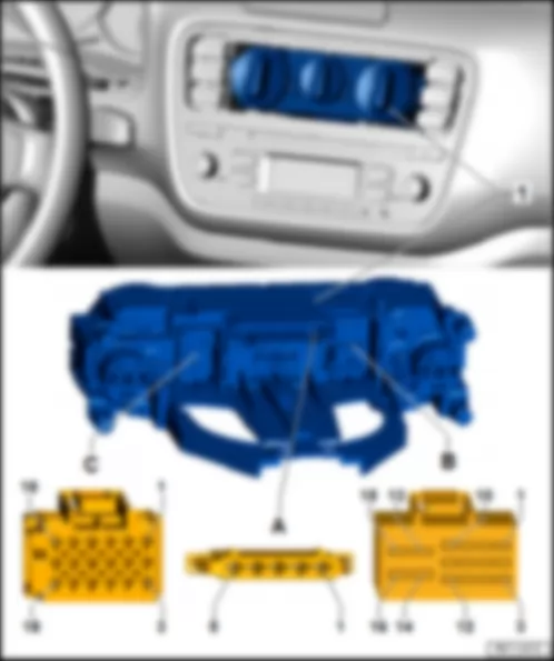
VW UP 2016 Air conditioning control unit J301
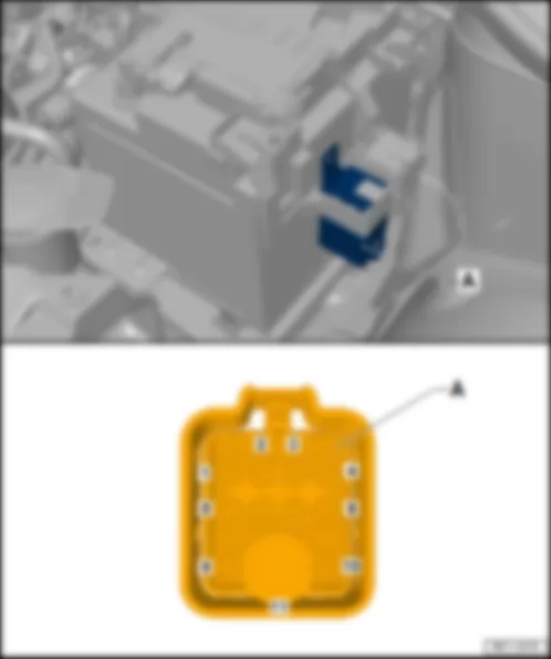
| Air conditioning control unit -J301- |
| Fitting Location: |
| 1 - | Air conditioning control unit -J301- |
| A - | 5-pin connector in the natural air fan switch -T5m- |
| B - | 16-pin connector in the air conditioning control unit -T16h- |
| C - | 18-pin connector in the air conditioning control unit -T18- |
| Connector description: Air conditioning control unit -J301- |
| T5m | - | Function | - | T16h | - | Function | - | T18 | Function |
| 1 | - | Blower level 4 Pre-resistance of the natural air fan w/ overheating fuse -N24- | - | 1 | - | AC signal, Engine control unit -J623- | - | 1 | -- |
| 2 | - | Blower level 3 Pre-resistance of the natural air fan w/ overheating fuse -N24- | - | 2 | - | Evaporator, GND, Engine control unit -J623- | - | 2 | -- |
| 3 | - | Blower level 2 Pre-resistance of the natural air fan w/ overheating fuse -N24- | - | 3 | - | -- | - | 3 | -- |
| 4 | - | Blower level 1 Pre-resistance of the natural air fan w/ overheating fuse -N24- | - | 4 | - | -- | - | 4 | -- |
| 5 | - | Power output +12V | - | 5 | - | -- | - | 5 | -- |
| - | 6 | - | -- | - | 6 | -- | |||
| - | 7 | - | -- | - | 7 | -- | |||
| - | 8 | - | -- | - | 8 | -- | |||
| - | 9 | - | -- | - | 9 | -- | |||
| - | 10 | - | Terminal 31 | - | 10 | -- | |||
| - | 11 | - | Terminal 15, High pressure sensor -G65- | - | 11 | -- | |||
| - | 12 | - | Terminal 58d | - | 12 | -- | |||
| - | 13 | - | -- | - | 13 | -- | |||
| - | 14 | - | -- | - | 14 | -- | |||
| - | 15 | - | -- | - | 15 | -- | |||
| - | 16 | - | -- | - | 16 | -- | |||
| - | 17 | -- | |||||||
| - | 18 | -- |
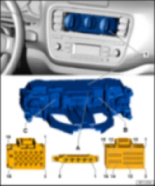
| Heating system control unit -J162- |
| Fitting Location: |
| 1 - | Heating system control unit -J162- |
| A - | 5-pin connector in the natural air fan switch -T5m- |
| B - | 16-pin connector in the heating control unit -T16h- |
| C - | 18-pin connector in the heating control unit -T18- |
| Connector description: Heating system control unit -J162- |
| T5m | - | Function | - | T16h | - | Function | - | T18 | Function |
| 1 | - | Blower level 4 Pre-resistance of the natural air fan w/ overheating fuse -N24- | - | 1 | - | -- | - | 1 | -- |
| 2 | - | Blower level 3 Pre-resistance of the natural air fan w/ overheating fuse -N24- | - | 2 | - | -- | - | 2 | -- |
| 3 | - | Blower level 2 Pre-resistance of the natural air fan w/ overheating fuse -N24- | - | 3 | - | -- | - | 3 | -- |
| 4 | - | Blower level 1 Pre-resistance of the natural air fan w/ overheating fuse -N24- | - | 4 | - | -- | - | 4 | -- |
| 5 | - | Power output +12V | - | 5 | - | -- | - | 5 | -- |
| - | 6 | - | -- | - | 6 | -- | |||
| - | 7 | - | -- | - | 7 | -- | |||
| - | 8 | - | -- | - | 8 | -- | |||
| - | 9 | - | -- | - | 9 | -- | |||
| - | 10 | - | Terminal 31 | - | 10 | -- | |||
| - | 11 | - | -- | - | 11 | -- | |||
| - | 12 | - | Terminal 58d | - | 12 | -- | |||
| - | 13 | - | -- | - | 13 | -- | |||
| - | 14 | - | -- | - | 14 | -- | |||
| - | 15 | - | -- | - | 15 | -- | |||
| - | 16 | - | -- | - | 16 | -- | |||
| - | 17 | -- | |||||||
| - | 18 | -- |
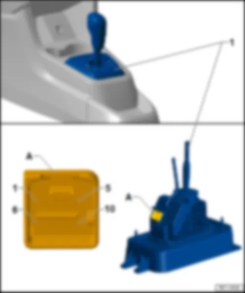
| Selector lever -E313- |
| Fitting Location: |
| 1 - | Selector lever -E313- |
| A - | 10-pin connector in the selector lever -T10n- |
| Connector description:Selector lever -E313- |
| T10n | - | Function |
| 1 | - | Terminal 31 |
| 2 | - | -- |
| 3 | - | -- |
| 4 | - | -- |
| 5 | - | Terminal 58d |
| 6 | - | -- |
| 7 | - | CAN-Bus, High |
| 8 | - | CAN-Bus, Low |
| 9 | - | Terminal 15,Fuse 8 in fuse holder A -SA8- |
| 10 | - | Terminal 30,Fuse 7 in fuse holder A -SA7- |
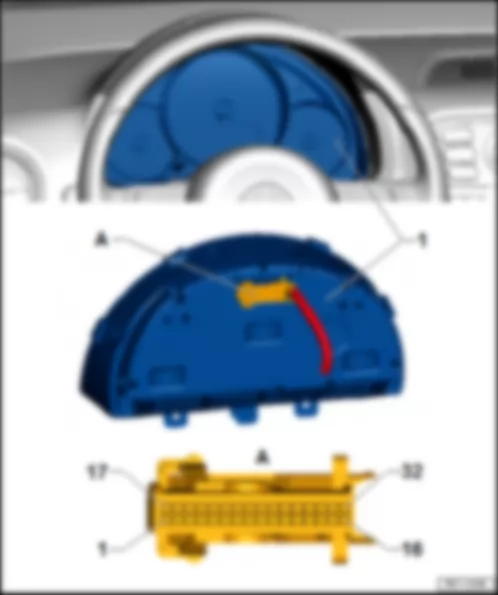
| Instrument cluster indicator control unit -J285- |
| Fitting Location: |
| 1 - | Instrument cluster indicator control unit -J285- |
| A - | 32-pole fitting connector in the instrument cluster -T32a- |
| Connector description: Instrument cluster indicator control unit -J285- |
| T32a | - | Function |
| 1 | - | Fuel gauge sensor |
| 2 | - | Fuel gauge sensor |
| 3 | - | -- |
| 4 | - | -- |
| 5 | - | -- |
| 6 | - | -- |
| 7 | - | Immobilizer reading coil |
| 8 | - | Immobilizer reading coil |
| 9 | - | -- |
| 10 | - | -- |
| 11 | - | -- |
| 12 | - | -- |
| 13 | - | Fog lights |
| 14 | - | Headlights |
| 15 | - | -- |
| 16 | - | Terminal 31 |
| 17 | - | -- |
| 18 | - | Low coolant |
| 19 | - | External temperature sensor |
| 20 | - | Terminal 31, Sensors mass |
| 21 | - | Multifunctional (MFA) above |
| 22 | - | Multifunctional (MFA) below |
| 23 | - | Multifunctional (MFA) OK/RESET |
| 24 | - | -- |
| 25 | - | Handbrake control switch |
| 26 | - | Brake oil level warning contact |
| 27 | - | Oil pressure |
| 28 | - | CAN-Bus, High |
| 29 | - | CAN-Bus, Low |
| 30 | - | -- |
| 31 | - | Terminal 15 |
| 32 | - | Terminal 30 |
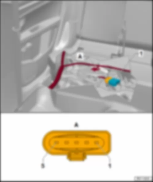
| Fuel pump control unit -J538- |
| Fitting Location: |
| 1 - | Fuel pump control unit -J538- |
| A - | 5-pin connector in the fuel pump control unit -T5o- |
| Connector description:Fuel pump control unit -J538- |
| T5o | - | Function |
| 1 | - | Fuel pump for initial input -G6- , + |
| 2 | - | Fuel pump for initial input -G6- , - |
| 3 | - | Terminal 87 |
| 4 | - | Terminal 31 |
| 5 | - | PWM signal,Engine control unit -J623- |
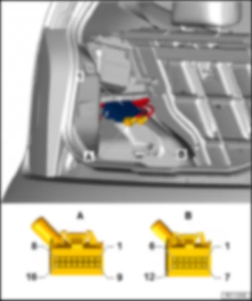
| Parking assist control unit -J446- |
| Fitting Location: |
| 1 - | Parking assist control unit -J446- |
| A - | 16-pin connector in the parking assist control unit -T16e- |
| B - | 12-pin connector in the parking assist control unit -T12f- |
| Connector description: Parking assist control unit -J446- |
| T12f | - | Function | - | T16e | - | Function |
| 1 | - | -- | - | 1 | - | Terminal 15, Fuse 10 in fuse holder A -SA10- |
| 2 | - | -- | - | 2 | - | Rear parking assist warning buzzer -H15- |
| 3 | - | Rear centre parking assist sensor -G796- | - | 3 | - | -- |
| 4 | - | Rear right parking assist sensor -G206- | - | 4 | - | -- |
| 5 | - | Rear left parking assist sensor -G203- | - | 5 | - | -- |
| 6 | - | -- | - | 6 | - | CAN-Bus, High |
| 7 | - | -- | - | 7 | - | -- |
| 8 | - | Sensor, Mass, rear | - | 8 | - | Terminal 31 |
| 9 | - | -- | - | 9 | - | -- |
| 10 | - | -- | - | 10 | - | Rear parking assist warning buzzer -H15- |
| 11 | - | Sensor, voltage, rear | - | 11 | - | -- |
| 12 | - | -- | - | 12 | - | -- |
| - | 13 | - | -- | |||
| - | 14 | - | -- | |||
| - | 15 | - | CAN-Bus, Low | |||
| - | 16 | - | -- |
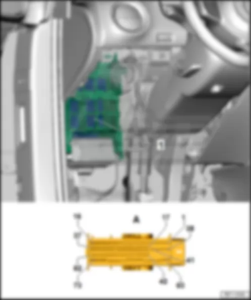
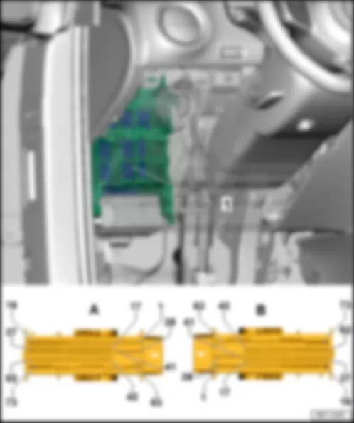
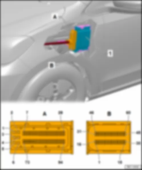
| Onboard network control unit: BFM -J519- |
| Fitting Location: |
| 1 - | Onboard network control unit -J519- |
| A - | 73-pole fitting connector in the onboard control unit -T73a- |
| Connector description: Onboard network control unit: BFM -J519- |
| T73a | - | Function |
| 1 | - | Wiper motor control unit -J400- |
| 2 | - | Wiper motor control unit -J400- |
| 3 | - | -- |
| 4 | - | Front interior light -W1- |
| 5 | - | Switch light lamp to disable interior monitoring -L118-1) |
| 6 | - | -- |
| 7 | - | Rear right turn signal lamp -M8- |
| 8 | - | Rear left turn signal lamp -M6- |
| 9 | - | Terminal 30, Fuse 29 in fuse holder A -SA29- |
| 10 | - | Rear lid central locking motor -V53- |
| 11 | - | Terminal 31 |
| 12 | - | Terminal 30, Fuse 41 in fuse holder A -SA41- |
| 13 | - | -- |
| 14 | - | Terminal 31 |
| 15 | - | Rear left door central locking motor -V115- , Driver door central locking motor -V56- , Passenger door central locking motor -V57- , Rear right door central locking motor -V97- |
| 16 | - | Rear left door central locking motor -V115- , Driver door central locking motor -V56- , Passenger door central locking motor -V57- , Rear right door central locking motor -V97- |
| 17 | - | -- |
| 18 | - | -- |
| 19 | - | -- |
| 20 | - | Alarm system ultrasound sensor -G209- |
| 21 | - | Rear window heating switch light lamp -L39- |
| 22 | - | -- |
| 23 | - | -- |
| 24 | - | Alarm horn relay -J641- |
| 25 | - | Warning light switch lamp -L35- |
| 26 | - | Switch light lamp to disable interior monitoring -L118-1) |
| 27 | - | Diagnosis terminal - CAN High |
| 28 | - | Diagnosis terminal - CAN Low |
| 29 | - | CAN-Bus, High |
| 30 | - | CAN-Bus, Low |
| 31 | - | Front lid / engine lid contact switch -F387- |
| 32 | - | Driver-side internal locking switch -E308- |
| 33 | - | Alarm system ultrasound sensor -G209- |
| 34 | - | Rear lid puller unlocking switch -E234- |
| 35 | - | Driver-side central locking unit -F220- |
| 36 | - | Driver-side central locking unit -F220- |
| 37 | - | Rear tailgate unlocking motor -V139- |
| 38 | - | Terminal 31 |
| 39 | - | -- |
| 40 | - | -- |
| 41 | - | -- |
| 42 | - | Terminal 30, Fuse 12 (30) of the battery fuse holder -S270- |
| 43 | - | Terminal 31 |
| 44 | - | Wiper motor control unit -J400- |
| 45 | - | Engine control unit -J623- , Brake light switch -F- |
| 46 | - | Windscreen wiper delay relay switch (intermittent operation) -E22- |
| 47 | - | Windscreen wiper delay relay switch (intermittent operation) -E22- |
| 48 | - | Reverse gear light switch -F4- |
| 49 | - | Light switch -E1- |
| 50 | - | Generator (Alternator) -C- , Voltage regulator -C1- |
| 51 | Terminal 15, Fuse 5 in fuse holder A -SA5- | |
| 52 | - | Terminal 50, Ignition switch -D- |
| 53 | - | Terminal S, Ignition switch -D- |
| 54 | - | Rear window wiper switch -E34- , Rear window wiper motor. -V12- , Rear window and windscreen washer pump -V59- |
| 55 | - | Rear window heating system switch -E230- |
| 56 | - | Windscreen wiper delay relay switch (intermittent operation) -E22- |
| 57 | - | Turn light/flashing light switch -E2- |
| 58 | - | Turn light/flashing light switch -E2- |
| 59 | - | Contact of the airbag coil and return spring with slip ring -F138- |
| 60 | - | Warning light switch -E3- |
| 61 | - | Driver-side central locking unit -F220- |
| 62 | - | Passenger-side central locking unit -F221- , Rear left central locking unit -F222- , Rear right central locking unit -F223- |
| 63 | - | Terminal 30, Fuse 49 in fuse holder A -SA49- |
| 64 | - | Front right turn signal lamp -M7- , Ext. passenger rear-view mirror turn signal lamp -L132- |
| 65 | - | Terminal 30, Fuse 32 in fuse holder A -SA32- |
| 66 | - | Front left turn signal lamp -M5- , Ext. driver rear-view mirror turn signal lamp -L131- |
| 67 | - | Treble horn -H2- |
| 68 | - | Terminal 30, Fuse 48 in fuse holder A -SA48- |
| 69 | - | Left brake light lamp -M9- , Right brake light lamp -M10- |
| 70 | - | -- |
| 71 | - | -- |
| 72 | - | Rear window defogger -Z1- |
| 73 | - | Terminal 30, Fuse 46 in fuse holder A -SA46- |
| Note
|
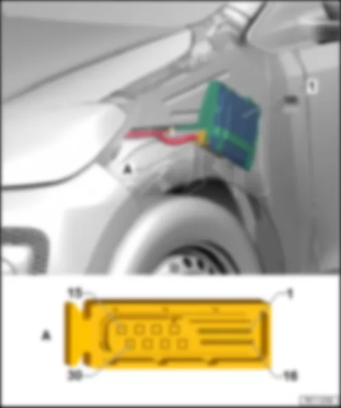
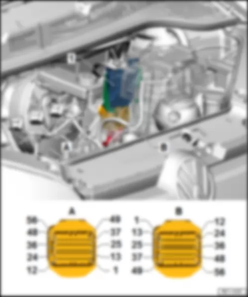
| Onboard network control unit: BCM -J519- |
| Fitting Location: |
| 1 - | Onboard network control unit -J519- |
| A - | 73-pole fitting connector in the onboard control unit -T73b- |
| B - | 73-pole fitting connector in the onboard control unit -T73c- |
| Connector description: Onboard network control unit: BCM -J519- |
| T73b | - | Function | - | T73c | - | Function |
| 1 | - | Sealed right headlight double-filament lamp -L2- | - | 1 | - | Sealed left headlight double-filament lamp -L1- |
| 2 | - | Sealed left headlight double-filament lamp -L1- | - | 2 | - | Sealed right headlight double-filament lamp -L2- , |
| 3 | - | -- | - | 3 | - | Left daytime running light lamp -L174-1) |
| 4 | - | Internal lighting, Front internal light -W1- | - | 4 | - | -- |
| 5 | - | Right daytime running light lamp -L175-1) | - | 5 | - | Rear left turn signal lamp -M6- |
| 6 | - | Rear left fog light -L46- ,.Instrument cluster -K- | - | 6 | - | Rear right turn signal lamp -M8- |
| 7 | - | Fog lights switch -E23- | - | 7 | - | License plate light -X- |
| 8 | - | -- | - | 8 | - | -- |
| 9 | - | -- | - | 9 | - | Left fog light lamp -L22- |
| 10 | - | Rear lid central locking motor -V53- | - | 10 | - | Right fog light lamp -L23- |
| 11 | - | Driver door central locking motor -V56- , Passenger door central locking motor -V57- , Rear right door central locking motor -V97- , Rear left door central locking motor -V115- | - | 11 | - | Terminal 30, Fuse 50 in fuse holder A -SA50- |
| 12 | - | Driver door central locking motor -V56- | - | 12 | - | Left reverse gear light lamp -M16- , Right reverse gear light lamp -M17- |
| 13 | - | -- | - | 13 | - | Terminal 30, Fuse 32 in fuse holder A -SA32- |
| 14 | - | Terminal 31 | - | 14 | - | Front left turn signal lamp -M5- , Ext. driver rear-view mirror turn signal lamp -L131- |
| 15 | - | Passenger door central locking motor -V57- , Rear right door central locking motor -V97- , Rear left door central locking motor -V115- | - | 15 | - | Front right turn signal lamp -M7- , Ext. passenger rear-view mirror turn signal lamp -L132- |
| 16 | - | Terminal 30, Fuse 41 in fuse holder A -SA41- | - | 16 | - | Left brake light lamp -M9- , Right brake light lamp -M10- |
| 17 | - | Rear left central locking unit -F222- | - | 17 | - | -- |
| 18 | - | Rear right central locking unit -F223- | - | 18 | - | CAN-Bus, Low |
| 19 | - | Driver-side central locking unit -F220- | - | 19 | - | CAN-Bus, High |
| 20 | - | Passenger-side central locking unit -F221- | - | 20 | - | Radio -R- |
| 21 | - | Passenger-side central locking unit -F221- | - | 21 | - | Radio -R- |
| 22 | - | Driver-side central locking unit -F220- | - | 22 | - | Diagnosis terminal, CAN-Low |
| 23 | - | Rear lid puller unlocking switch -E234- | - | 23 | - | Diagnosis terminal, CAN-High |
| 24 | - | Driver-side central locking unit -F220- | - | 24 | - | Alarm system ultrasound sensor -G209- |
| 25 | - | Driver-side internal locking switch -E308- | - | 25 | - | -- |
| 26 | - | Rear right central locking unit -F223- | - | 26 | - | -- |
| 27 | - | Front lid / engine lid contact switch -F387- | - | 27 | - | Windscreen wiper delay relay switch (intermittent operation) -E22- |
| 28 | - | Warning light switch -E229- | - | 28 | - | -- |
| 29 | - | Contact of the airbag coil and return spring with slip ring -F138- | - | 29 | - | Light switch -E1-1) |
| 30 | - | Rear lid locking unit -F256- | - | 30 | - | Alarm system ultrasound sensor -G209- |
| 31 | - | Rear lid locking unit -F256- | - | 31 | - | Rear window heating system switch -E230- |
| 32 | - | Turn light/flashing light switch -E2- | - | 32 | - | Wiper motor control unit -J400- |
| 33 | - | Turn light/flashing light switch -E2- | - | 33 | - | -- |
| 34 | - | Rear left central locking unit -F222- | - | 34 | - | -- |
| 35 | - | -- | - | 35 | - | -- |
| 36 | - | -- | - | 36 | - | -- |
| 37 | - | -- | - | 37 | - | -- |
| 38 | - | -- | - | 38 | - | Terminal 31 |
| 39 | - | -- | - | 39 | - | Terminal 30, Fuse 29 in fuse holder A -SA29- |
| 40 | - | Front right side lamp -M3- , Rear right lamp -M2- | - | 40 | - | -- |
| 41 | - | Front left side lamp -M1- , Rear left lamp -M4- | - | 41 | - | -- |
| 42 | - | Terminal S, Ignition switch -D- | - | 42 | - | -- |
| 43 | - | Engine control unit -J623- , Brake light switch -F- | - | 43 | - | Light switch -E1- |
| 44 | - | Terminal 15, Ignition switch -D- | - | 44 | - | -- |
| 45 | - | Light switch -E1- | - | 45 | - | -- |
| 46 | - | -- | - | 46 | - | -- |
| 47 | - | -- | - | 47 | - | -- |
| 48 | - | -- | - | 48 | - | Reverse gear light switch -F4- |
| 49 | - | -- | - | 49 | - | Generator (Alternator) -C- , Voltage regulator -C1- |
| 50 | - | -- | - | 50 | - | Terminal 50, Ignition switch -D- |
| 51 | - | -- | - | 51 | - | Ignition switch -D- , Relief relay for contact X -J59- |
| 52 | - | -- | - | 52 | - | Light switch -E1- |
| 53 | - | Alarm horn relay -J641- | - | 53 | - | Windscreen wiper delay relay switch (intermittent operation) -E22- |
| 54 | - | -- | - | 54 | - | Instrument cluster -K- |
| 55 | - | Starter inhibitor relay -J207-3) | - | 55 | - | Automated gearbox control unit -J514- |
| 56 | - | Warning light switch lamp -L35- | - | 56 | - | -- |
| 57 | - | Switch light lamp to disable interior monitoring -L118-2) | - | 57 | - | Instrument cluster -K- |
| 58 | - | Switch light lamp to disable interior monitoring -L118-2) | - | 58 | - | -- |
| 59 | - | -- | - | 59 | - | Terminal 30, Fuse 12 (30) of the battery fuse holder -S270- |
| 60 | - | Rear window heating switch light lamp -L39- | - | 60 | - | Terminal 31 |
| 61 | - | -- | - | 61 | - | Rear window wiper switch -E34- , Rear window wiper motor. -V12- , Rear window and windscreen washer pump -V59- |
| 62 | - | Manual switch for headlights/low beams and headlight flashing -E4- | - | 62 | - | Windscreen wiper delay relay switch (intermittent operation) -E22- |
| 63 | - | Terminal 30, Fuse 33 in fuse holder A -SA33- | - | 63 | - | Rear window defogger -Z1- |
| 64 | - | -- | - | 64 | - | -- |
| 65 | - | Internal lighting, Front internal light -W1- | - | 65 | - | -- |
| 66 | - | Terminal 30, Fuse 27 in fuse holder A -SA27- | - | 66 | - | -- |
| 67 | - | -- | - | 67 | - | Terminal 30, Fuse 46 in fuse holder A -SA46- |
| 68 | - | Terminal 30, Fuse 49 in fuse holder A -SA49- | - | 68 | - | Terminal 30, Fuse 32 in fuse holder A -SA32- |
| 69 | - | Wiper motor control unit -J400- | - | 69 | - | -- |
| 70 | - | Terminal 31 | - | 70 | - | -- |
| 71 | - | Wiper motor control unit -J400- | - | 71 | - | -- |
| 72 | - | Treble horn -H2- | - | 72 | - | -- |
| 73 | - | Terminal 30, Fuse 48 in fuse holder A -SA48- | - | 73 | - | -- |
| Note
|
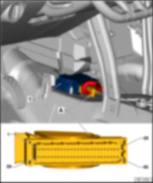
| Airbag control unit -J234- |
| Fitting Location: |
| 1 - | Airbag control unit -J234- |
| A - | 50-pin connector in the airbag control unit -T50a- |
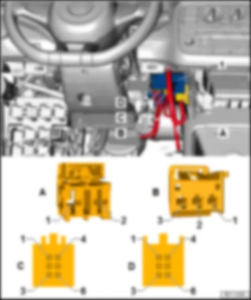
| Power steering control unit -J500- |
| Fitting Location: |
| 1 - | Power steering control unit -J500- |
| A - | 2-pin fitting connector in the power steering control unit -T2ah- |
| B - | 3-pin fitting connector in the power steering control unit -T3d- |
| C - | 6-pin fitting connector in the power steering control unit -T6k- |
| D - | 6-pin fitting connector in the power steering control unit -T6l- |
| Connector description: Power steering control unit -J500- |
| T2ah | - | Function | - | T3d | - | Function |
| 1 | - | Terminal 30 | - | 1 | - | CAN-Bus, Low |
| 2 | - | Terminal 31 | - | 2 | - | CAN-Bus, High |
| - | 3 | - | Terminal 15 |
| |
| T6k | - | Function | - | T6l | - | Function |
| 1 | - | Reference signal 2, Engine rotor position sensor for active steering -G751- | - | 1 | - | Reference voltage, Steering sensor -G269- |
| 2 | - | Reference signal 2 (sine 1), Engine rotor position sensor for active steering -G751- | - | 2 | - | -- |
| 3 | - | Reference signal 4 (sine 2), Engine rotor position sensor for active steering -G751- | - | 3 | - | Main signal, Steering sensor -G269- |
| 4 | - | Reference signal 1, Engine rotor position sensor for active steering -G751- | - | 4 | - | GND, Steering sensor -G269- |
| 5 | - | Position signal 3 (cosine 2), Engine rotor position sensor for active steering -G751- | - | 5 | - | Sub signal, Steering sensor -G269- |
| 6 | - | Position signal 1 (cosine 1), Engine rotor position sensor for active steering -G751- | - | 6 | - | Supply, Steering sensor -G269- |

