VW BORA 2007 – Anti-lock brake system (ABS), Anti-lock brake system (ABS), with electronic differential lock (EDL) and traction control system (TCS) . Wiring diagrams, Pin Connector, Location – Wiring diagrams for cars
AUTOMOTIVE ELECTRICIANS PORTAL
VW BORA 2007 – Anti-lock brake system (ABS), Anti-lock brake system (ABS), with electronic differential lock (EDL) and traction control system (TCS) . Wiring diagrams, Pin Connector, Location
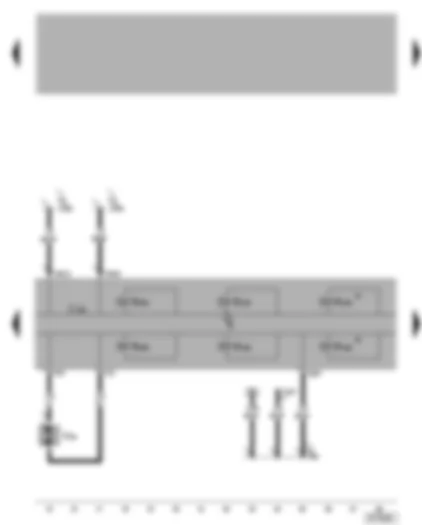
Wiring Diagram VW BORA 2007 - ABS with EDL control unit - brake light switch https://portal-diagnostov.com/license.html
https://portal-diagnostov.com/license.html
Automotive Electricians Portal FZCO
Automotive Electricians Portal FZCO A Battery F Brake light switch J104 ABS/ABS with EDL control unit, in engine compartment, left J217 Automatic gearbox control unit J... Engine control units S13 Fuse in fuse box S178 Fuse -6- (30), in fuse box/battery S179 Fuse -7- (30), in fuse box/battery T3 3-pin connector T10w 10-pin connector, white, in protective housing for connectors, in plenum chamber, left T25 25-pin connector T68 68-pin connector 501 Screw connection -2- (30), on relay plate A18 Connection (54), in dash panel wiring harness A121 Connection (high bus), in dash panel wiring harness A122 Connection (low bus), in dash panel wiring harness ** Up to August 2000 -••- From September 2000 --- Only models with automatic gearbox
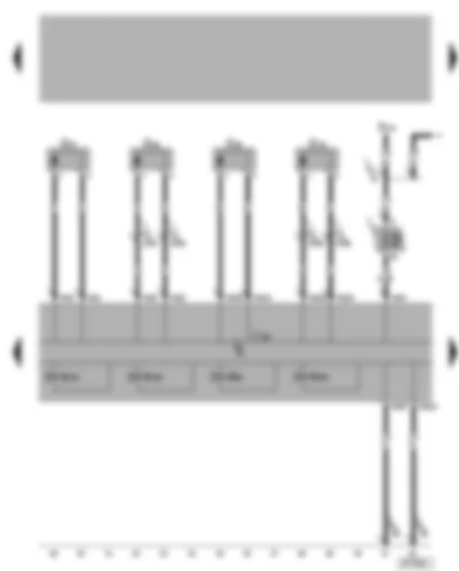
Wiring Diagram VW BORA 2007 - ABS with EDL control unit - ABS hydraulic pump J104 ABS/ABS with EDL control unit, in engine compartment, left N125 Differential lock valve 1* N126 Differential lock valve 2* N133 ABS inlet valve, rear right N134 ABS inlet valve, rear left N135 ABS outlet valve, rear right N136 ABS outlet valve, rear left T2 2-pin connector T16 16-pin connector, in dash panel centre, self-diagnosis connection*** T25 25-pin connector V64 ABS hydraulic pump A76 Connection (diagnosis wire K), in dash panel wiring harness A133 Connection (ABS impulse left), in dash panel wiring harness A134 Connection (ABS impulse right), in dash panel wiring harness * Only models with EDL/TCS *** Models for Mexico, self-diagnosis connection left under dash panel
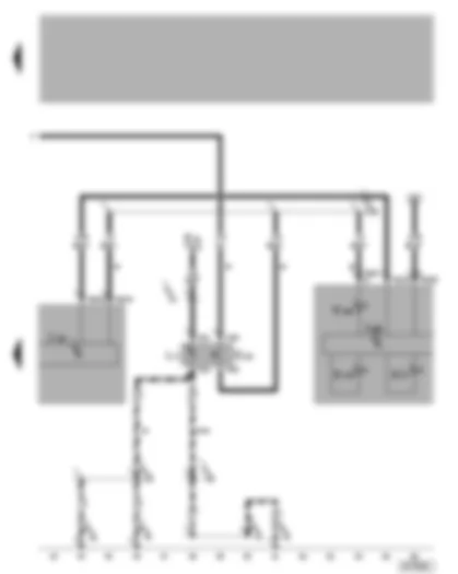
Wiring Diagram VW BORA 2007 - ABS with EDL control unit - speed sensors D Ignition/starter switch G44 Rear right speed sensor G45 Front right speed sensor G46 Rear left speed sensor G47 Front left speed sensor J104 ABS/ABS with EDL control unit, in engine compartment, left N99 ABS inlet valve, front right N100 ABS outlet valve, front right N101 ABS inlet valve, front left N102 ABS outlet valve, front left S9 Fuse in fuse box T25 25-pin connector 65 Earth point, longitudinal member left, front A2 Positive (+) connection (15), in dash panel wiring harness D146 Connection (rear left speed sensor +), in engine compartment wiring harness D147 Connection (rear left speed sensor -), in engine compartment wiring harness D148 Connection (rear right speed sensor +), in engine compartment wiring harness D149 Connection (rear right speed sensor -), in engine compartment wiring harness
Wiring Diagram VW BORA 2007 - ABS with EDL control unit - dash panel insert - traction control system switch - ABS warning lamp - brake system warning lamp - TCS warning lamp E20 Switches and instruments, lighting control E132 Traction control system switch* J104 ABS/ABS with EDL control unit, in engine compartment, left J285 Control unit with display in dash panel insert K47 ABS warning lamp K118 Brake system warning lamp K155 TCS warning lamp* L71 Traction control switch illumination* T3c 3-pin connector T6 6-pin connector* T25 25-pin connector T32 32-pin connector, blue T32a 32-pin connector, green 81 Earth connection -1-, in dash panel wiring harness 135 Earth connection -2-, in dash panel wiring harness A4 Positive (+) connection (58b), in dash panel wiring harness A132 Connection (TCS), in dash panel wiring harness * Only models with TCS -••- From May 2001 -••- Up to April 2000
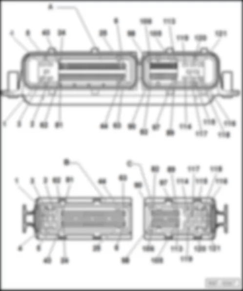
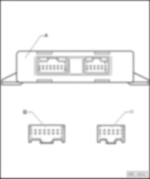
VW BORA 2007 Motronic control unit J220 Motronic control unit -J220-
– Central under plenum chamber cover -Arrow-
Designation of connector:
A - Motronic control unit -J220-
B - 81-pin connector -T81-
C - 40-pin connector -T40-
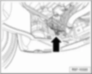
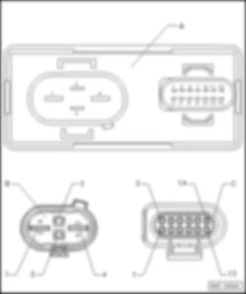
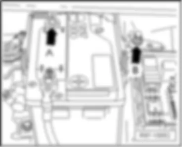
– in engine compartment, bottom left -arrow-
Designation of connector:
A - Radiator fan control unit -J293-
B - 4-pin connector, on radiator fan control unit -T4v-
C - 14-pin connector, on radiator fan control unit -T14-
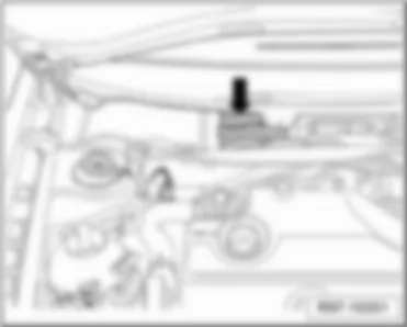
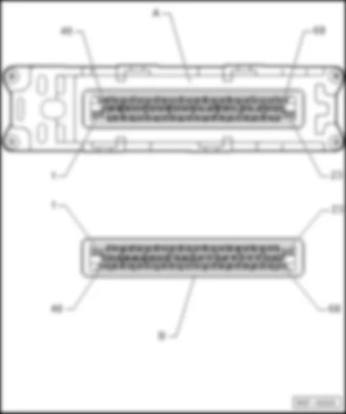
– in engine compartment, right -arrow-
Designation of connector:
A - Automatic gearbox control unit -J217-
B - 68-pin connector, on automatic gearbox control unit -T68-
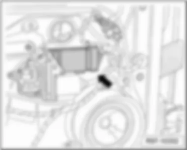
– behind the door trim, front left -arrow-
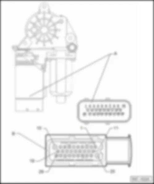
Designation of connector:
A - Driver door control unit -J386-
B - 29-pin connector, on driver door control unit -T29-
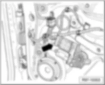
– behind the door trim, front right -arrow-
Designation of connector:
A - Front passenger door control unit -J387-
B - 29-pin connector, on front passenger door control unit -T29a-
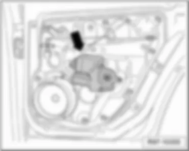
– behind the door trim, rear left -arrow-
Designation of connector:
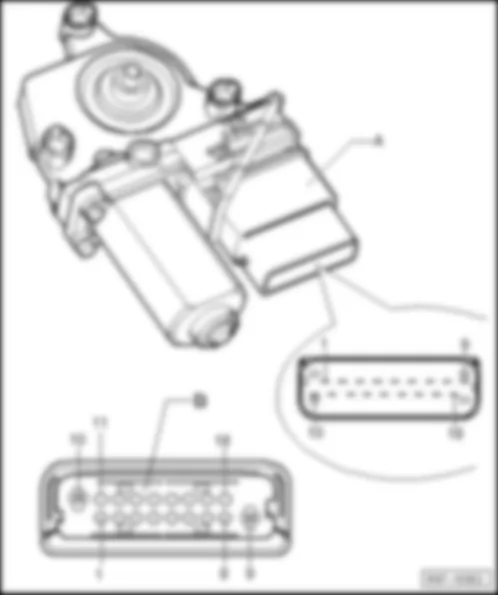
A - Rear left door control unit -J388-
B - 18-pin connector, on left rear door control unit -T18-
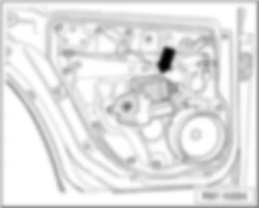
– behind the door trim, rear right -arrow-
Designation of connector:
A - Rear right door control unit -J389-
B - 18-pin connector, on left rear door control unit -T18b-
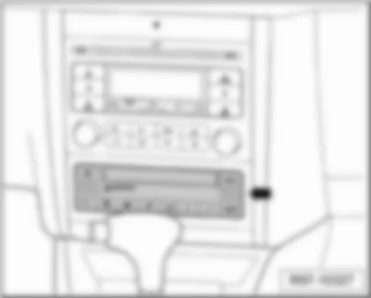
– In centre console, under radio -arrow-
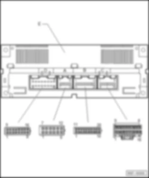
Designation of connector:
E - Climatronic control unit -J255-
A - 12-pin connector, on Climatronic control unit -T12c-
B - 20-pin connector, on Climatronic control unit -T20-
C - 16-pin connector, on Climatronic control unit -T16b-
D - 16-pin connector, on Climatronic control unit -T16a-
– Behind glove compartment, front passenger side -arrow-
Designation of connector:
A - Convenience system central control unit -J393-
B - 15-pin connector, on convenience system central control unit -T15-
C - 23-pin connector, on convenience system central control unit -T23-
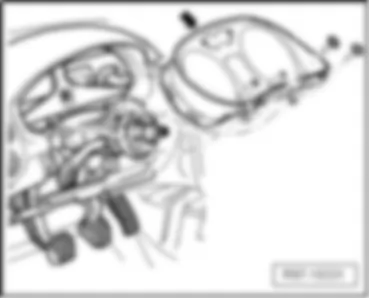
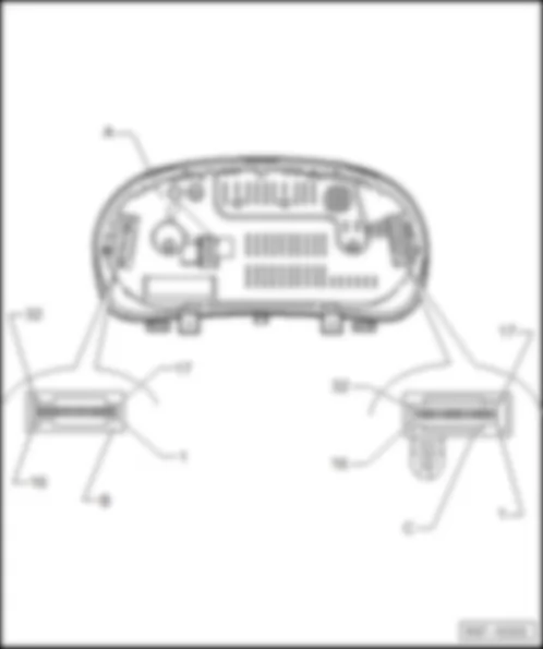
– Behind instrument cluster-arrow-
Designation of connector:
A - Control unit with display in dash panel insert -J285-
C - 32-pin connector, blue, on instrument cluster control unit with indicator unit -T32-
8 - Coolant temperature indicator sensor
22 - Coolant shortage indicator sender
29 - Brake fluid level warning contact
31 - Front left belt switch
B - 32-pin connector, green, on instrument cluster control unit with indicator unit -T32a-
2 - Immobilizer reader coil
4 - Terminal for CAN-Bus / control
6 - Windscreen washer fluid level sender
8 - Terminal for CAN-Bus "high" - convenience -
9 - Terminal for CAN-Bus "low" - convenience -
12 - Radiator fan control unit
13 - Handbrake warning switch
14 - Terminal for ASR/ESP
17 - Immobilizer reader coil
19 - Terminal for CAN-Bus high
20 - Terminal for CAN-Bus low
22 - Contact switch on bonnet / bonnet for alarm system
23 - Multifunction display memory switch
24 - Multifunction display memory switch
25 - Multifunction display memory switch
26 - Ambient temperature sensor
27 - Terminal for CAN-Bus high
28 - Terminal for CAN-Bus low
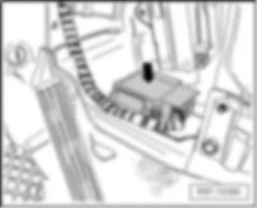
– under centre console -arrow-
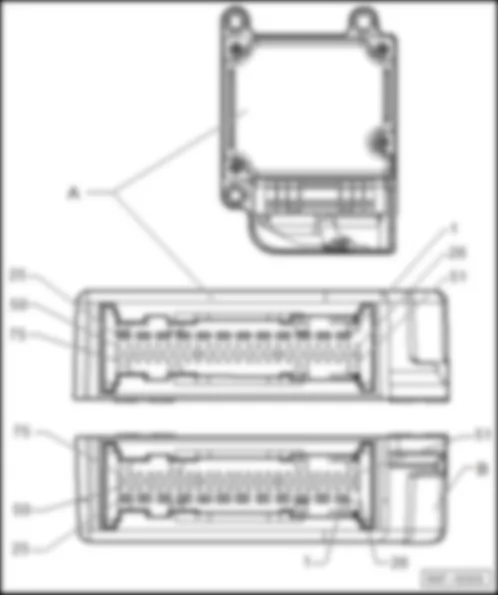
Designation of connector:
A - Airbag control unit -J234-
B - 75-pin connector, on airbag control unit -T75-
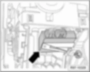
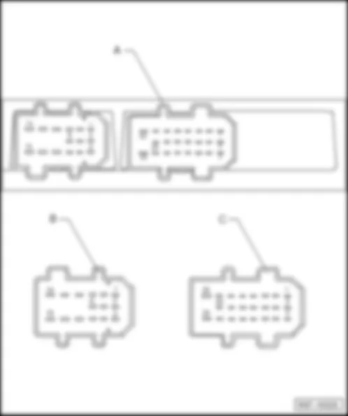
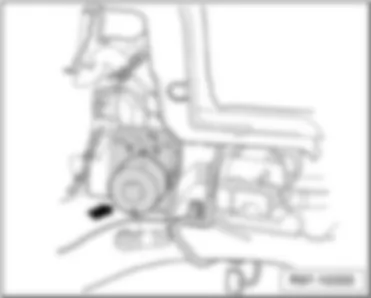
– In engine compartment, left -arrow-
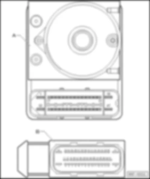
Designation of connector:
A - ABS control unit -J104-
B - 47-pin connector, on ABS control unit -T47-
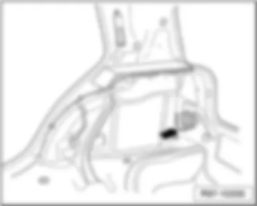
– Behind right luggage compartment lining-arrow-
Designation of connector:
A - Parking aid control unit -J446-
B - 16-pin connector, on parking aid control unit -T16z-
C - 12-pin connector, on parking aid control unit -T12ka-
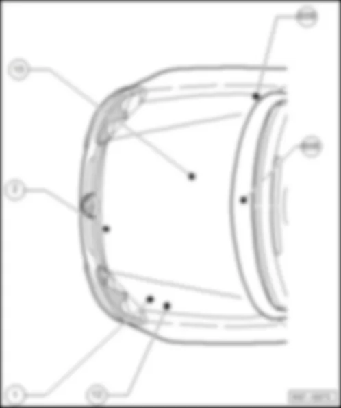
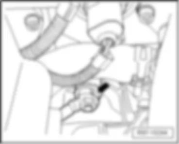
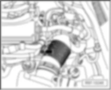
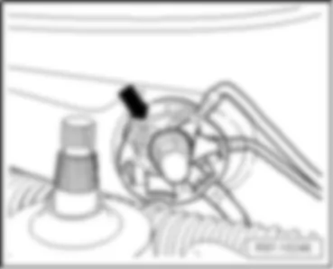
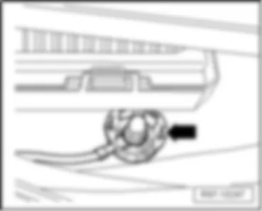
VW BORA 2007 Earth strap, battery - body - Arrow A - VW BORA 2007 Earth points in the engine compartment Earth points in the engine compartment
1 Earth strap, battery - body
2 Earth strap, gearbox - body
12 Earth point, on left in engine compartment
15 Earth point, on cylinder head
608 Earth point, in centre of plenum chamber
609 Earth point, on right in plenum chamber
Earth strap, battery - body - Arrow A -
Earth point, in engine compartment, left -arrow B-
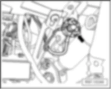
Earth strap, gearbox - body- Arrow -
Earth connection on cylinder head - arrow -
Earth connection on water deflector, centre - arrow -
Earth connection on water deflector, right - arrow -
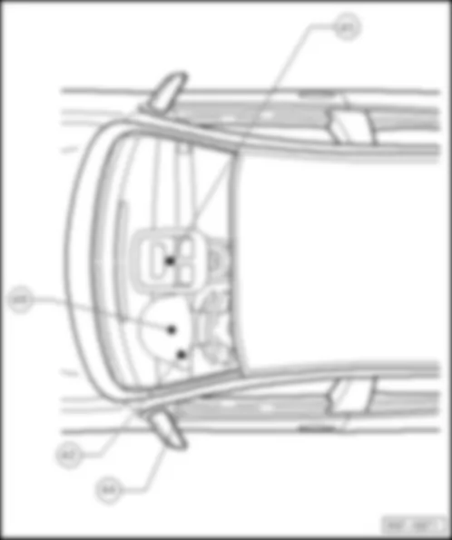
Earth points in passenger compartment
42 Earth point, next to steering column
44 Earth point, lower part of left A-pillar
45 Earth point, centre behind dash panel
49 Earth connection, on steering column
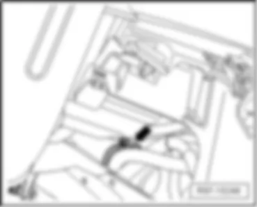
Earth point, next to steering column- arrow -
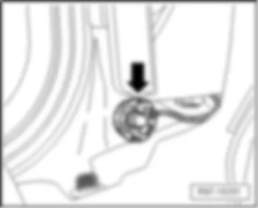
Earth connection, lower part of left A-pillar -arrow-
Earth connection, centre behind dash panel- Arrow -
Earth connection on steering column - arrow -
Earth points in rear part of vehicle
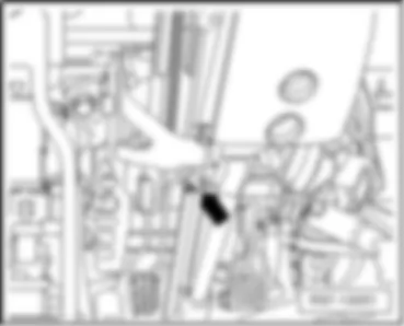
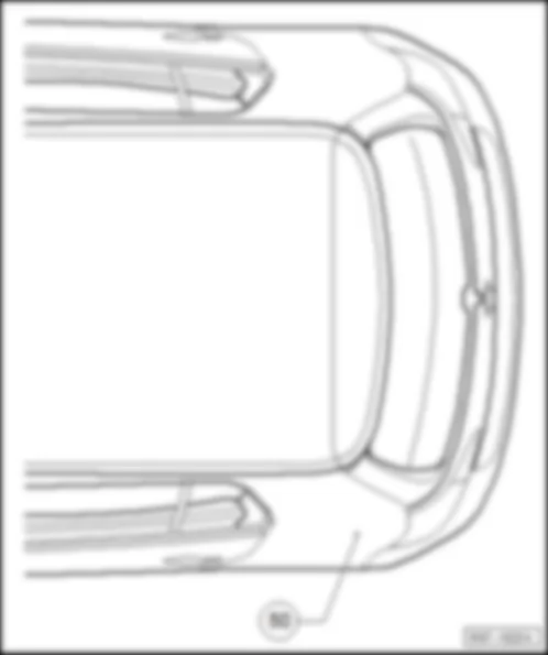
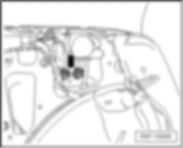
50 Earth points, in luggage compartment, left
Earth points in luggage compartment, left - Arrow -
We use cookies on our website to give you the most relevant experience by remembering your preferences and repeat visits. By clicking “Accept All”, you consent to the use of ALL the cookies. However, you may visit "Cookie Settings" to provide a controlled consent.
Manage consent