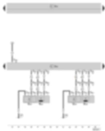
Wiring Diagram SKODA SUPERB II 2015 - Starter relay 1 - starter relay 2 - fuse holder C in the dash panel

| B | Starter |
| J519 | Vehicle voltage control unit |
| J623 | Engine control unit |
| J906 | Starter relay 1 |
| J907 | Starter relay 2 |
| SC2 | Fuse 2 on fuse holder C |
| T52c | 52-pin connector, at onboard supply control unit (brown) |
| T94a | 94-pin connector, at engine control unit |
| B273 | Positive connection (15) in main wiring harness |
| B276 | Positive connection (50) in main wiring harness |
| B281 | Positive connection 5 (15a) in main wiring harness |
Wiring Diagram SKODA SUPERB II 2015 - Control unit for ELV - starter button - fuse holder C in the dash panel
| E378 | Starter button |
| F319 | Selector lever locked in position P switch |
| J519 | Vehicle voltage control unit |
| J764 | Control unit for ELV |
| L190 | Lamp for ignition starter switch illumination |
| SC21 | Fuse 21 on fuse holder C |
| T4bw | 4-pin connector, at starter button |
| T16t | 16-pin connector, at control unit for ELV |
| 371 | Earth connection 6 in main wiring harness |
| B325 | Positive connection 11 (30a) in main wiring harness |
| * | for vehicles with automatic gearbox |
Wiring Diagram SKODA SUPERB II 2015 - Control unit for ELV - steering column lock control element - entry and start authorisation control unit - fuse holder C in the dash panel
| J518 | Entry and start authorisation control unit |
| J519 | Vehicle voltage control unit |
| J764 | Control unit for ELV |
| N360 | Steering column lock control element |
| SC20 | Fuse 20 on fuse holder C |
| T16t | 16-pin connector, at control unit for ELV |
| T32e | 32-pin connector, at entry and start authorisation control unit |
| T52c | 52-pin connector, at onboard supply control unit (brown) |
| 372 | Earth connection 7 in main wiring harness |
| 374 | Earth connection 9 in main wiring harness |
| 638 | Earth point on right A-pillar |
| B325 | Positive connection 11 (30a) in main wiring harness |
| B626 | Positive connection 2 (15) in main wiring harness |
Wiring Diagram SKODA SUPERB II 2015 - Entry and start authorisation control unit - exterior door handle touch sensor driver's side - exterior door handle touch sensor front passenger side - driver side aerial for entry and start authorisation - front passenger side aerial for entry and start authorisation
| G415 | Exterior door handle touch sensor driver's side |
| G416 | Exterior door handle touch sensor front passenger side |
| J518 | Entry and start authorisation control unit |
| J519 | Vehicle voltage control unit |
| R134 | Driver side aerial for entry and start authorisation |
| R135 | Front passenger side aerial for entry and start authorisation |
| T4bx | 4-pin connector, at exterior door handle touch sensor driver's side |
| T4by | 4-pin connector, at exterior door handle touch sensor front passenger side |
| T28a | 28-pin connector, on the right A-pillar |
| T28b | 28-pin connector, on the left A-pillar |
| T32e | 32-pin connector, at entry and start authorisation control unit |
| 206 | Earth connection, in front passenger door wiring harness |
| 267 | Earth connection 2 in driver door wiring harness |
Wiring Diagram SKODA SUPERB II 2015 - Entry and start authorisation control unit - interior aerial 1 for entry and start authorisation - entry and start authorisation aerial rear left - entry and start authorisation aerial rear right - aerial in rear bumper for entry and start authorisation
| J518 | Entry and start authorisation control unit |
| J519 | Vehicle voltage control unit |
| R136 | Aerial in rear bumper for entry and start authorisation |
| R138 | Interior aerial 1 for entry and start authorisation |
| R165 | Entry and start authorisation aerial rear left |
| R166 | Entry and start authorisation aerial rear right |
| T32e | 32-pin connector, at entry and start authorisation control unit |
Wiring Diagram SKODA SUPERB II 2015 - Entry and start authorisation control unit - data bus diagnostic interface - immobilizer - dash panel insert
| D2 | Immobilizer reading coil |
| J119 | Multi-function display |
| J285 | Control unit in dash panel insert |
| J362 | Immobilizer control unit |
| J518 | Entry and start authorisation control unit |
| J519 | Vehicle voltage control unit |
| J533 | Data bus diagnostic interface |
| K | Dash panel insert |
| T20c | 20-pin connector, at data bus diagnostic interface |
| T32a | 32-pin connector, at dash panel insert |
| T32e | 32-pin connector, at entry and start authorisation control unit |
| B397 | Connection 1 (convenience CAN bus, High) in main wiring harness |
| B406 | Connection 1 (convenience CAN bus, Low) in main wiring harness |
| B708 | Connection 1 (CAN bus dash panel insert High) in main wiring harness |
| B709 | Connection 1 (CAN bus dash panel insert Low) in main wiring harness |
Can't find your car? Check -> DiagnostData.com!