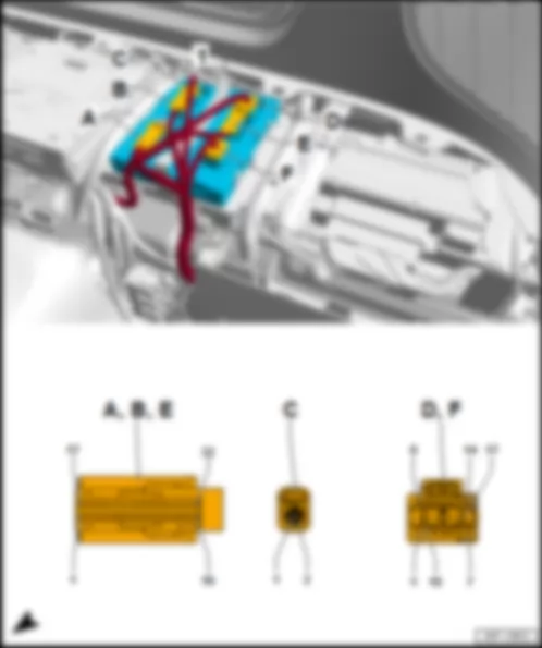
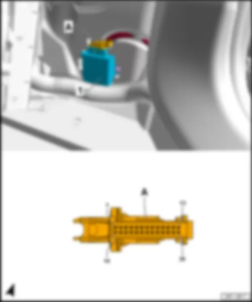
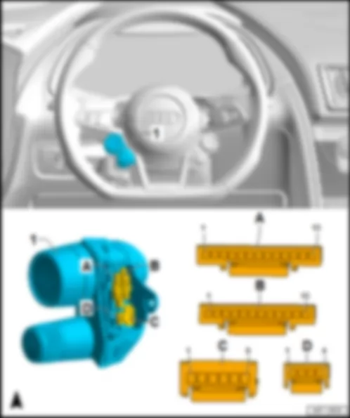
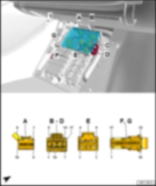
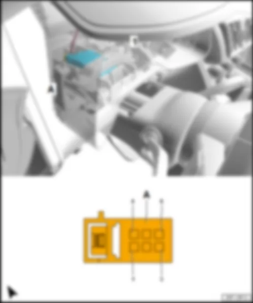
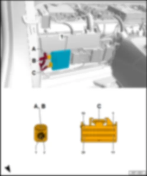
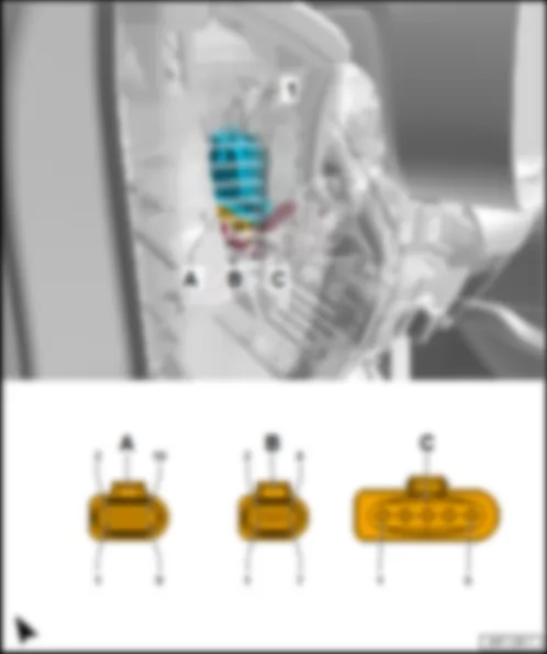
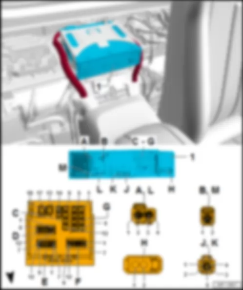
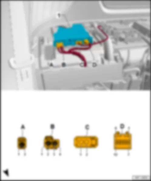
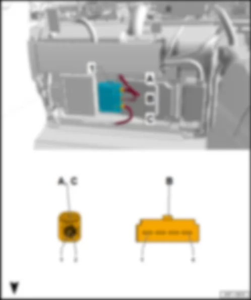
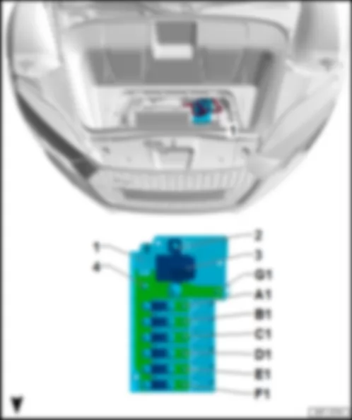
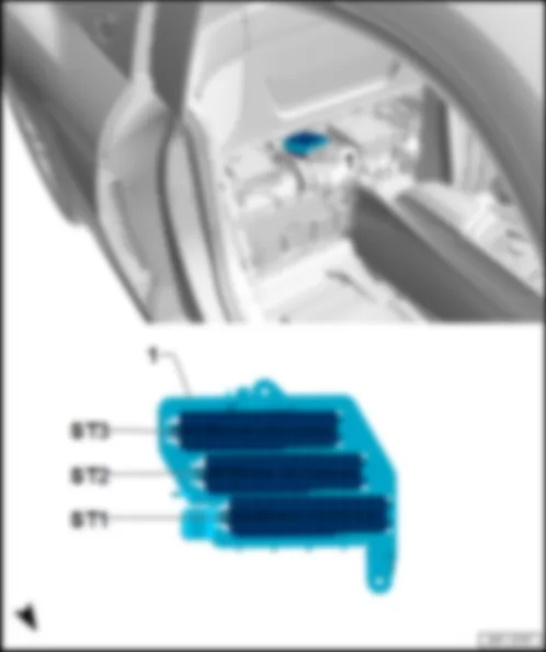
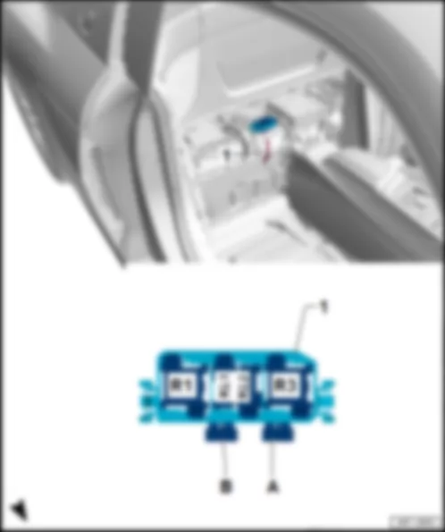
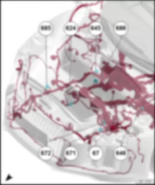
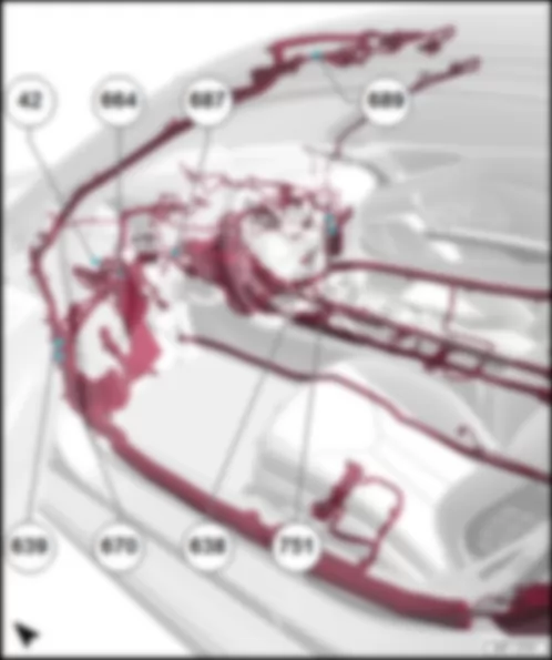
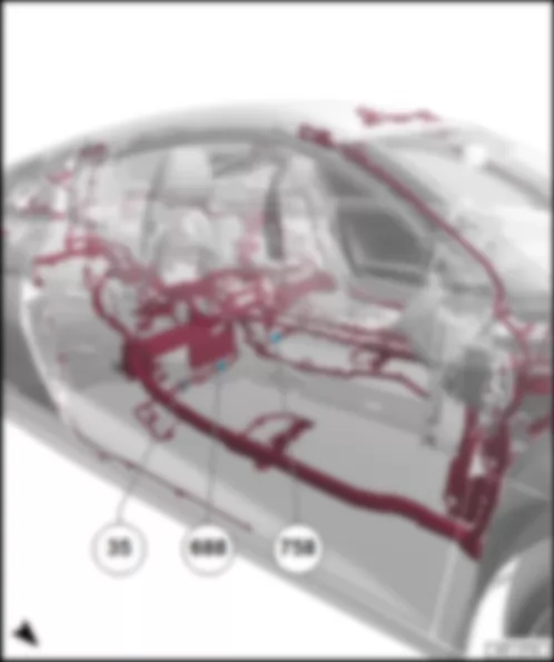
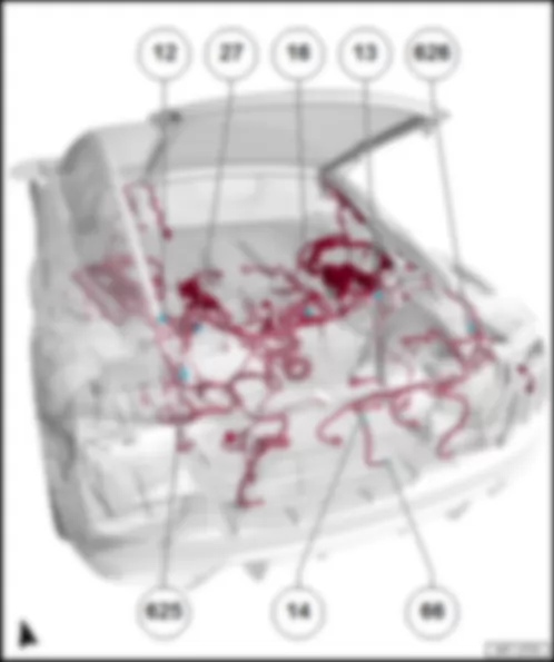
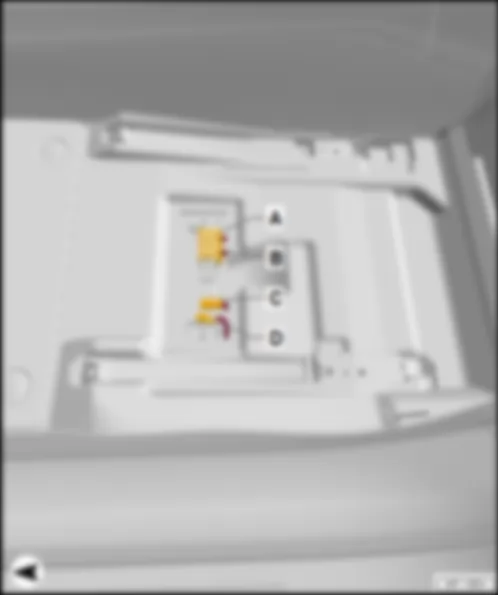
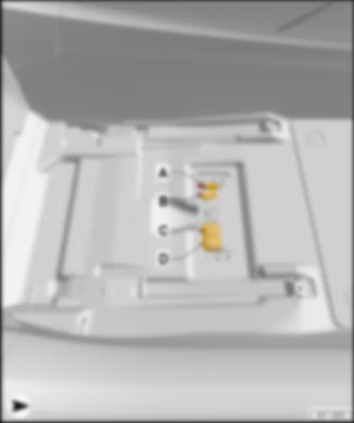
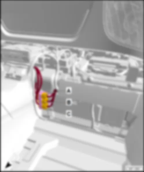
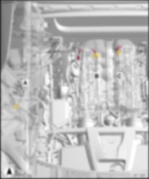
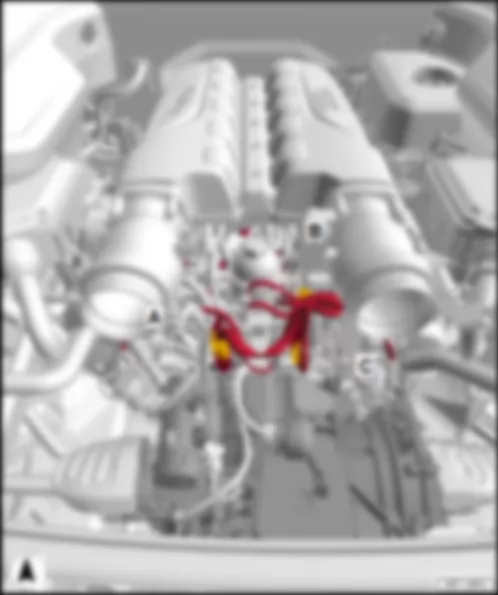
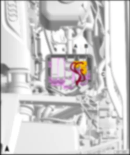
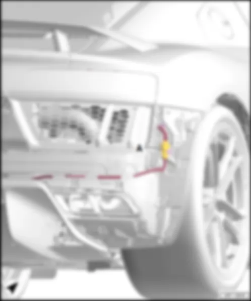
Wiring Diagram AUDI R8 2017 - Onboard supply control unit

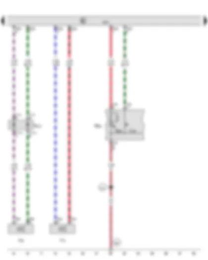
Wiring Diagram AUDI R8 2017 - Centre switch module in dash panel - Parking aid button - Rear parking aid warning buzzer - Front parking aid warning buzzer - Onboard supply control unit - Parking aid warning lamp
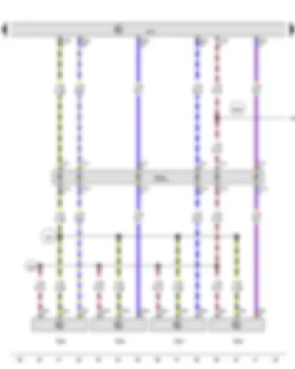
Wiring Diagram AUDI R8 2017 - Front right parking aid sender - Front centre right parking aid sender - Front centre left parking aid sender - Front left parking aid sender - Onboard supply control unit
| G252 | Front right parking aid sender |
| G253 | Front centre right parking aid sender |
| G254 | Front centre left parking aid sender |
| G255 | Front left parking aid sender |
| J519 | Onboard supply control unit |
| T3ai | 3-pin connector, black |
| T3ak | 3-pin connector, black |
| T3al | 3-pin connector, black |
| T3am | 3-pin connector, black |
| T14j | 14-pin connector, black |
| T14jx | 14-pin connector, black |
| T16e | 16-pin connector, brown |
| T32a | 32-pin connector, black |
| TSFVL | Coupling point on front left bumper |
| 348 | Earth connection (parking aid), in front bumper wiring harness |
| B468 | Connection 4, in main wiring harness |
| X65 | Connection (parking aid), in front bumper wiring harness |
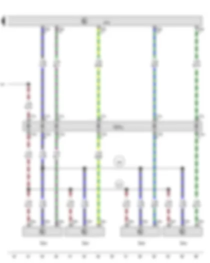
Wiring Diagram AUDI R8 2017 - Rear left parking aid sender - Rear centre left parking aid sender - Rear centre right parking aid sender - Rear right parking aid sender - Onboard supply control unit
| G203 | Rear left parking aid sender |
| G204 | Rear centre left parking aid sender |
| G205 | Rear centre right parking aid sender |
| G206 | Rear right parking aid sender |
| J519 | Onboard supply control unit |
| T3an | 3-pin connector, black |
| T3ao | 3-pin connector, black |
| T3ap | 3-pin connector, black |
| T3aq | 3-pin connector, black |
| T10c | 10-pin connector, black |
| T10cx | 10-pin connector, black |
| T32a | 32-pin connector, black |
| TSFHL | Coupling point on rear left bumper |
| 470 | Earth connection 1, in rear bumper wiring harness |
| B468 | Connection 4, in main wiring harness |
| X68 | Positive connection (parking aid), in rear bumper wiring harness |
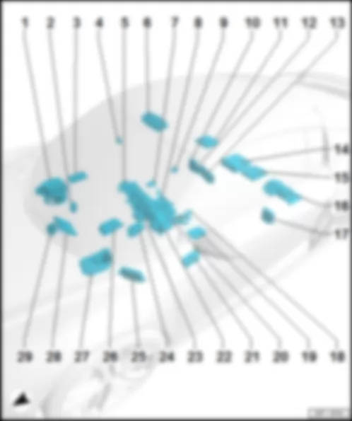
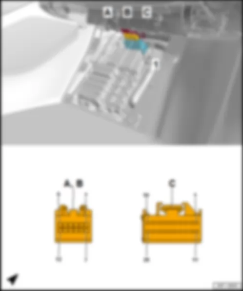
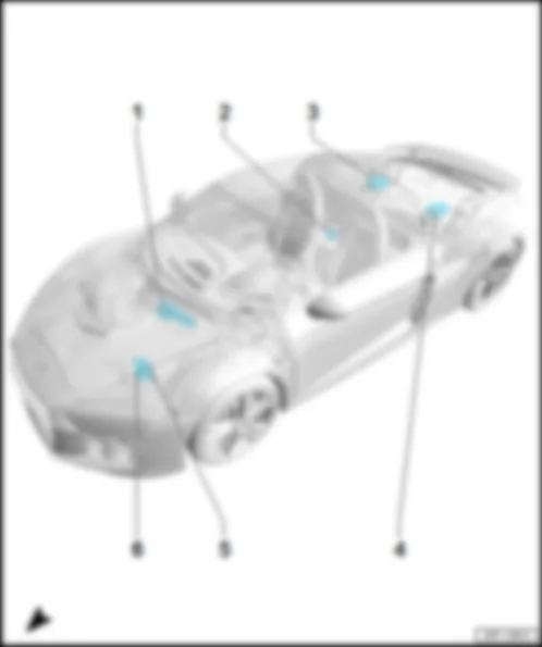
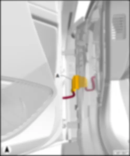
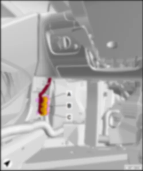
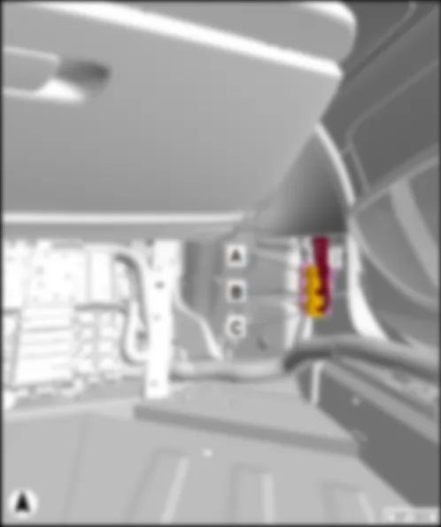
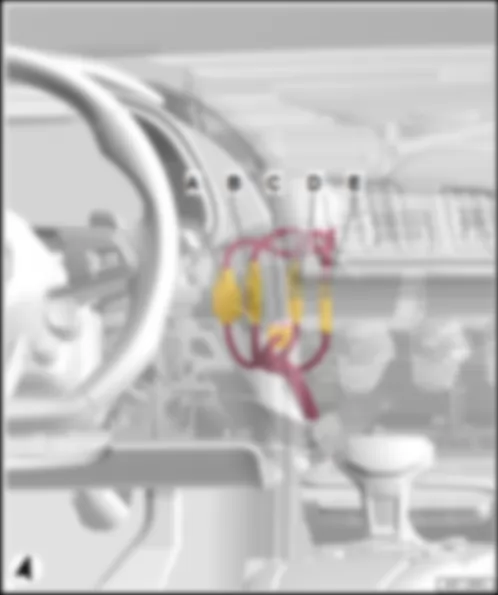
AUDI R8 2017 Overview of control units in middle part of vehicle
Overview of control units in middle part of vehicle | | Seat and steering column adjustment control unit with memory -J136- /front passenger seat adjustment control unit with memory -J521- |
| q | Connector assignment, seat and steering column adjustment control unit with memory -J136- |
| q | Connector assignment, front passenger seat adjustment control unit with memory -J521- |
| Door control unit -J386- /-J387- |
| q | Connector assignment, driver door control unit -J386- |
| q | Connector assignment, front passenger door control unit -J387- |
| q | Fitting location, right-hand drive models |
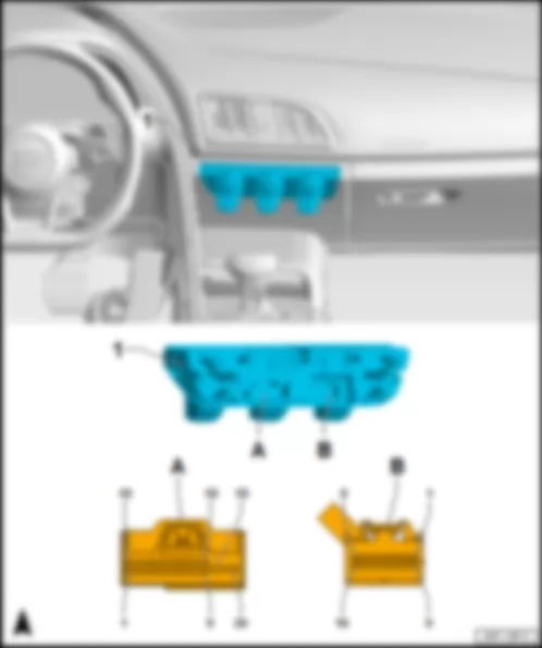
AUDI R8 2017 Fitting location Operating and display unit for Climatronic air conditioning system E87
Fitting location Operating and display unit for Climatronic air conditioning system -E87- |
| 1 - | Operating and display unit for Climatronic air conditioning system -E87- |
| B - | 16-pin connector -T16i- , brown |
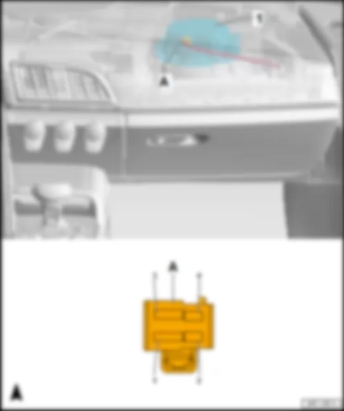
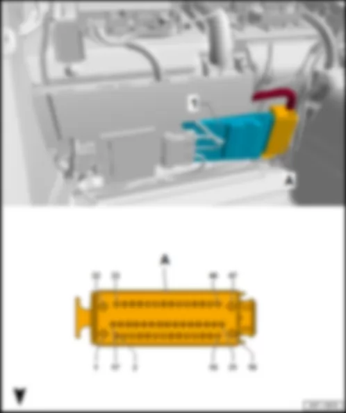
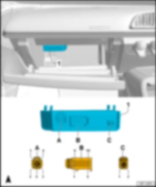
AUDI R8 2017 Fitting location, fresh air blower control unit J126
Fitting location, fresh air blower control unit -J126- |
| Behind the glove component on front heater and air conditioner unit. |
| 1 - | Fresh air blower control unit -J126- |
| Connector assignment, fresh air blower control unit -J126- |
| | | -T4ar- (A) | Designation |
| 1 | Terminal 31, to 638 earth point on right A-pillar |
| 2 | |
| 3 | Terminal 30, from fuse carrier 2 -ST2- in fuse holder C -SC- |
| 4 | LIN bus, from operating and display unit for Climatronic air conditioning system -E87- |
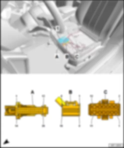
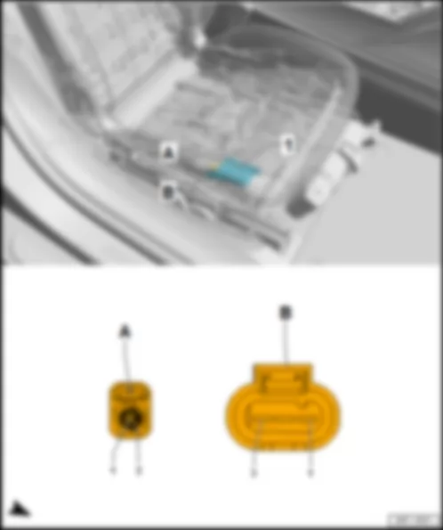
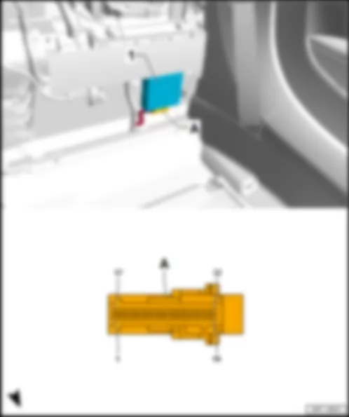
AUDI R8 2017
Fitting location, seat and steering column adjustment control unit with memory -J136- /front passenger seat adjustment control unit with memory -J521- |
| 1 - | Seat and steering column adjustment control unit with memory -J136- /front passenger seat adjustment control unit with memory -J521- |
| 26-pin connector -T26b- /-T26c- , black |
| q | 26-pin connector -T26b- on seat and steering column adjustment control unit with memory -J136- |
| q | 26-pin connector -T26c- on front passenger seat adjustment control unit with memory -J521- |
| 16-pin connector -T16k- /-T16l- , black |
| q | 16-pin connector -T16k- on seat and steering column adjustment control unit with memory -J136- |
| q | 16-pin connector -T16l- on front passenger seat adjustment control unit with memory -J521- |
| 12-pin connector -T12n- /-T12o- , black |
| q | 12-pin connector -T12n- on seat and steering column adjustment control unit with memory -J136- |
| q | 12-pin connector -T12o- on front passenger seat adjustment control unit with memory -J521- |
| Connector assignment, seat and steering column adjustment control unit with memory -J136- |
| -T26b- (A) | Designation | | -T26b- (A) | Designation |
| 1 | Valve for upper air cushion of driver side lumbar support -N715- | | 14 | |
| 2 | Valve for upper air cushion of driver side lumbar support -N715- | | 15 | |
| 3 | Valve for lower air cushion of driver side lumbar support -N714- | | 16 | |
| 4 | Valve for lower air cushion of driver side lumbar support -N714- | | 17 | Earth supply for valves -N716- /-N717- |
| 5 | Earth supply for valves -N714- /-N715- and pressure sensors -G945- /-G946- | | 18 | Earth line, to 140 earth connection 2 in seat adjustment wiring harness |
| 6 | | | 19 | Seat depth adjustment sender -G378- |
| 7 | Positive supply for pressure sensors -G945- /-G946- | | 20 | Longitudinal adjustment sender for driver seat -G218- |
| 8 | Compressor for multicontour driver seat -V439- | | 21 | Driver seat rake adjustment sender -G232- |
| 9 | Compressor for multicontour driver seat -V439- | | 22 | Driver seat height adjustment sender -G231- |
| 10 | Valve for air cushion of backrest side bolsters on driver side -N717- | | 23 | Backrest adjustment sender for driver seat -G219- |
| 11 | Valve for air cushion of backrest side bolsters on driver side -N717- | | 24 | |
| 12 | Valve for air cushion of seat bolsters on driver side -N716- | | 25 | Pressure sensor 2 in driver seat -G946- |
| 13 | Valve for air cushion of seat bolsters on driver side -N716- | | 26 | Pressure sensor 1 in driver seat -G945- |
| -T16k- (B) | Designation | | -T12n- (C) | Designation |
| 1 | Driver seat rake adjustment switch -E222- in driver seat adjustment operating unit -E470- | | 1 | Driver seat rake adjustment motor -V243- |
| 2 | Driver seat height adjustment switch -E364- in driver seat adjustment operating unit -E470- | | 2 | Driver seat rake adjustment motor -V243- |
| 3 | Driver seat backrest adjustment switch -E96- in driver seat adjustment operating unit -E470- | | 3 | Driver seat longitudinal adjustment motor -V28- |
| 4 | Coding lead, to contact 12 in connector -T16k- | | 4 | Driver seat longitudinal adjustment motor -V28- |
| 5 | Comfort low CAN bus to B406 connection 1 (comfort low CAN bus) in main wiring harness | | 5 | Driver seat backrest adjustment motor -V45- |
| 6 | Comfort high CAN bus, to B397 connection 1 (comfort high CAN bus) in main wiring harness | | 6 | Driver seat backrest adjustment motor -V45- |
| 7 | | | 7 | Driver seat height adjustment motor -V245- |
| 8 | | | 8 | Driver seat height adjustment motor -V245- |
| 9 | Seat depth adjustment button -E350- in driver seat adjustment operating unit -E470- | | 9 | Driver seat depth adjustment motor -V256- |
| 10 | Driver seat longitudinal adjustment switch -E363- in driver seat adjustment operating unit -E470- | | 10 | Driver seat depth adjustment motor -V256- |
| 11 | Earth line, to M10 connection 1 in driver seat adjustment wiring harness | | 11 | Terminal 31, to 639 earth point on left A-pillar |
| 12 | Coding lead, to contact 4 in connector -T16k- | | 12 | Terminal 30, from driver seat adjustment thermal fuse 1 -S44- on relay and fuse carrier 3 -SR3- |
| 13 | Lumbar support height adjustment button -E335- in switch module for driver seat -E663- | | | |
| 14 | Lumbar support longitudinal adjustment button -E336- in switch module for driver seat -E663- | | | |
| 15 | Driver seat bolster adjustment button -E587- in switch module for driver seat -E663- | | | |
| 16 | Driver seat backrest side bolster adjustment button -E589- in switch module for driver seat -E663- | | | |
| Connector assignment of control unit for front passenger seat adjustment with memory function -J521- |
| -T26c- (A) | Designation | | -T26c- (A) | Designation |
| 1 | Valve for upper air cushion of front passenger side lumbar support -N719- | | 14 | |
| 2 | Valve for upper air cushion of front passenger side lumbar support -N719- | | 15 | |
| 3 | Valve for lower air cushion of front passenger side lumbar support -N718- | | 16 | |
| 4 | Valve for lower air cushion of front passenger side lumbar support -N718- | | 17 | Earth supply for valves -N720- /-N721- |
| 5 | Earth supply for valves -N718- /-N719- and pressure sensors -G947- /-G948- | | 18 | Earth line, to 413 earth connection 4 in seat adjustment wiring harness |
| 6 | | | 19 | Front passenger seat depth adjustment sender -G724- |
| 7 | Positive supply for pressure sensors -G947- /-G948- | | 20 | Longitudinal adjustment sender for front passenger seat -G278- |
| 8 | Compressor for multicontour front passenger seat -V440- | | 21 | Front passenger seat rake adjustment sender -G359- |
| 9 | Compressor for multicontour front passenger seat -V440- | | 22 | Front passenger seat height adjustment sender -G607- |
| 10 | Valve for air cushion of backrest side bolsters on front passenger side -N721- | | 23 | Backrest adjustment sender for front passenger seat -G279- |
| 11 | Valve for air cushion of backrest side bolsters on front passenger side -N721- | | 24 | |
| 12 | Valve for air cushion of seat bolsters on front passenger side -N720- | | 25 | Pressure sensor 2 in front passenger seat -G948- |
| 13 | Valve for air cushion of seat bolsters on front passenger side -N720- | | 26 | Pressure sensor 1 in front passenger seat -G947- |
| -T16l- (B) | Designation | | -T12o- (C) | Designation |
| 1 | Front passenger seat rake adjustment button -E334- in front passenger seat adjustment operating unit -E471- | | 1 | Front passenger seat rake adjustment motor -V244- |
| 2 | Front passenger seat height adjustment switch -E365- in front passenger seat adjustment operating unit -E471- | | 2 | Front passenger seat rake adjustment motor -V244- |
| 3 | Front passenger seat backrest adjustment switch -E98- in front passenger seat adjustment operating unit -E471- | | 3 | Front passenger seat longitudinal adjustment motor -V31- |
| 4 | Coding lead, to contact 12 in connector -T16l- | | 4 | Front passenger seat longitudinal adjustment motor -V31- |
| 5 | Comfort low CAN bus to B407 connection 2 (comfort low CAN bus) in main wiring harness | | 5 | Front passenger seat backrest adjustment motor -V46- |
| 6 | Comfort high CAN bus, to B398 connection 2 (comfort high CAN bus) in main wiring harness | | 6 | Front passenger seat backrest adjustment motor -V46- |
| 7 | | | 7 | Front passenger seat height adjustment motor -V246- |
| 8 | | | 8 | Front passenger seat height adjustment motor -V246- |
| 9 | Front passenger seat depth adjustment button -E867- in front passenger seat adjustment operating unit -E471- | | 9 | Front passenger seat depth adjustment motor -V257- |
| 10 | Front passenger seat longitudinal adjustment switch -E64- in front passenger seat adjustment operating unit -E471- | | 10 | Front passenger seat depth adjustment motor -V257- |
| 11 | Earth line, to M18 connection 1 in front passenger seat adjustment wiring harness | | 11 | Terminal 31, to 751 earth point 2 on right A-pillar |
| 12 | Coding lead, to contact 4 in connector -T16l- | | 12 | Terminal 30, from front passenger seat adjustment thermal fuse 1 -S46- on relay and fuse carrier 3 -SR3- |
| 13 | Front passenger side lumbar support height adjustment button -E882- in switch module for front passenger seat -E664- | | | |
| 14 | Front passenger side lumbar support longitudinal adjustment button -E883- in switch module for front passenger seat -E664- | | | |
| 15 | Front passenger seat bolster adjustment button -E588- in switch module for front passenger seat -E664- | | | |
| 16 | Front passenger seat backrest side bolster adjustment button -E590- in switch module for front passenger seat -E664- | | | |
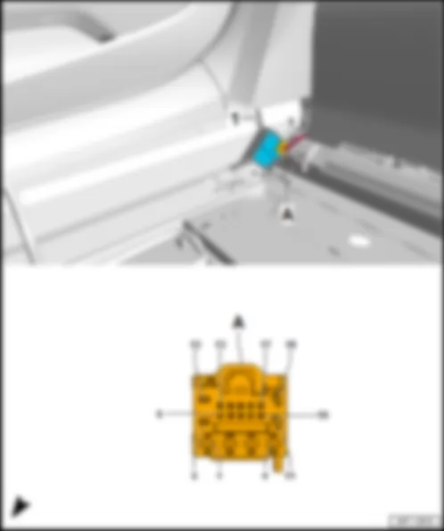
AUDI R8 2017 Fitting location, adjustable rear spoiler control unit J223
Fitting location, adjustable rear spoiler control unit -J223- |
| On the right sill right at the back in front of the rear wall. |
| 1 - | Adjustable rear spoiler control unit -J223- |
| Connector assignment, adjustable rear spoiler control unit -J223- |
| -T18a- (A) | Designation | | -T18a- (A) | Designation |
| 1 | | | 10 | Rear spoiler -VX73- |
| 2 | Rear spoiler adjustment motor -V52- in rear spoiler -VX73- | | 11 | Limit switch 1 for rear spoiler adjustment -F135- in rear spoiler -VX73- |
| 3 | Terminal 31, to 35 earth point under front passenger seat | | 12 | Rear spoiler adjustment switch -E127- in switch module in centre of dash panel -EX22- |
| 4 | Terminal 30, from fuse carrier 2 -ST2- in fuse holder D -SD- | | 13 | |
| 5 | Rear spoiler adjustment motor -V52- in rear spoiler -VX73- | | 14 | |
| 6 | Rear spoiler adjustment switch -E127- in switch module in centre of dash panel -EX22- | | 15 | |
| 7 | LIN bus, from convenience system central control unit -J393- | | 16 | |
| 8 | | | 17 | Limit switch 2 for rear spoiler adjustment -F136- in rear spoiler -VX73- |
| 9 | | | 18 | Rear spoiler -VX73- |
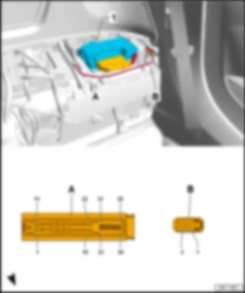
AUDI R8 2017 Fitting location, airbag control unit J234
Fitting location, airbag control unit -J234- |
| Under centre console at front on centre tunnel |
| 1 - | Airbag control unit -J234- |
| A - | 100-pin connector -T100a- , yellow |
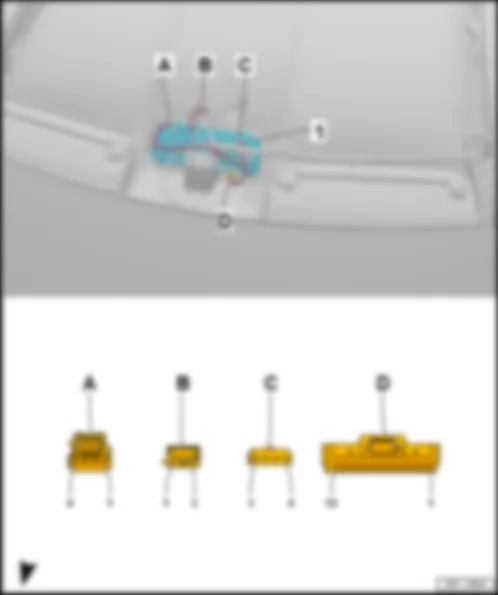
AUDI R8 2017 Fitting location, electronically controlled damping control unit J250
Fitting location, electronically controlled damping control unit -J250- |
| Under the rear shelf at the bottom right on the rear wall next to the centre tunnel. |
| 1 - | Electronically controlled damping control unit -J250- |
| Connector assignment, electronically controlled damping control unit -J250- |
| -T47b- (A) | Designation | | -T47b- (A) | Designation | | -T47b- (A) | Designation |
| 1 | Terminal 15, from fuse carrier 2 -ST21- in fuse holder D -SD- | | 17 | Rear left vehicle level sender -G76- | | 33 | Rear left vehicle level sender -G76- |
| 2 | Rear left vehicle level sender -G76- | | 18 | Front right vehicle level sender -G289- | | 34 | Front right vehicle level sender -G289- |
| 3 | Front right vehicle level sender -G289- | | 19 | | | 35 | Rear right vehicle level sender -G77- |
| 4 | | | 20 | Rear right vehicle level sender -G77- | | 36 | Front left vehicle level sender -G78- |
| 5 | Rear right vehicle level sender -G77- | | 21 | Front left vehicle level sender -G78- | | 37 | Running gear sensors CAN bus low, to B783 connection 2 (running gear sensors CAN bus low) in main wiring harness |
| 6 | Front left vehicle level sender -G78- | | 22 | | | 38 | Running gear sensors CAN bus high, to B773 connection 2 (running gear sensors CAN bus high) in main wiring harness |
| 7 | | | 23 | | | 39 | |
| 8 | | | 24 | | | 40 | |
| 9 | | | 25 | | | 41 | |
| 10 | | | 26 | | | 42 | Rear left shock absorber damping adjustment valve -N338- |
| 11 | | | 27 | Front right shock absorber damping adjustment valve -N337- | | 43 | Rear left shock absorber damping adjustment valve -N338- |
| 12 | | | 28 | Front right shock absorber damping adjustment valve -N337- | | 44 | |
| 13 | | | 29 | | | 45 | Rear right shock absorber damping adjustment valve -N339- |
| 14 | | | 30 | Front left shock absorber damping adjustment valve -N336- | | 46 | Rear right shock absorber damping adjustment valve -N339- |
| 15 | | | 31 | Front left shock absorber damping adjustment valve -N336- | | 47 | Terminal 30, from fuse carrier 1 -ST1- in fuse holder D -SD- |
| 16 | Terminal 31, to 35 earth point under front passenger seat | | 32 | | | | |
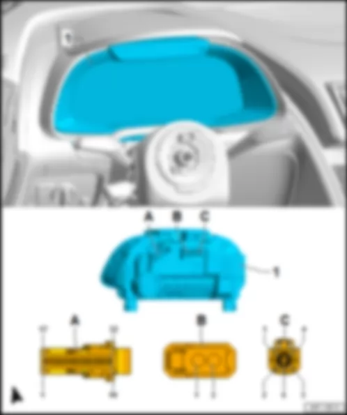
AUDI R8 2017 Fitting location, control unit in dash panel insert J285
Fitting location, control unit in dash panel insert -J285- |
| In driver side dash panel. |
| 1 - | Control unit in dash panel insert -J285- |
| B - | 2-pin connector -T2ee- , black |
| Connector assignment, control unit in dash panel insert -J285- |
| -T32k- (A) | Designation | | -T32k- (A) | Designation | | -T32k- (A) | Designation |
| 1 | Ring break diagnosis, to B444 connection 1 (diagnosis) in main wiring harness | | 12 | | | 23 | |
| 2 | | | 13 | | | 24 | |
| 3 | Dash panel insert CAN bus low, to A205 connection (dash panel insert CAN bus low) in dash panel wiring harness | | 14 | | | 25 | CAN bus, control unit 1 for information electronics, low, to E147 connection 1 (CAN bus, control unit 1 for information electronics, low) |
| 4 | Dash panel insert CAN bus high, to A204 connection (dash panel insert CAN bus high) in dash panel wiring harness | | 15 | | | 26 | CAN bus, control unit 1 for information electronics, high, to E145 connection 1 (CAN bus, control unit 1 for information electronics, high) |
| 5 | Earth supply for fuel level sender | | 16 | | | 27 | |
| 6 | Fuel gauge sender -G- | | 17 | | | 28 | |
| 7 | Fuel level sender 2 -G169- | | 18 | | | 29 | |
| 8 | Dash panel insert operating buttons -E493- | | 19 | | | 30 | Terminal 31, to 664 earth point on left behind dash panel |
| 9 | Fuel level sender 3 -G237- | | 20 | | | 31 | |
| 10 | Fuel level sender 4 -G393- | | 21 | | | 32 | Terminal 30, from fuse carrier 3 -ST3- in fuse holder C -SC- |
| 11 | | | 22 | | | | |
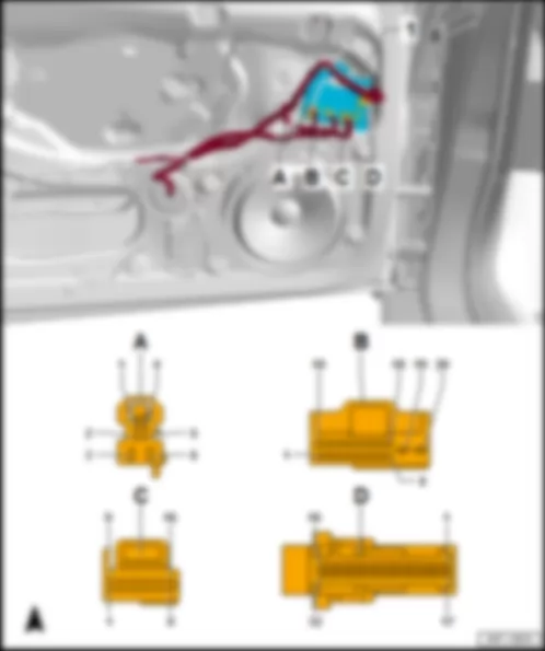
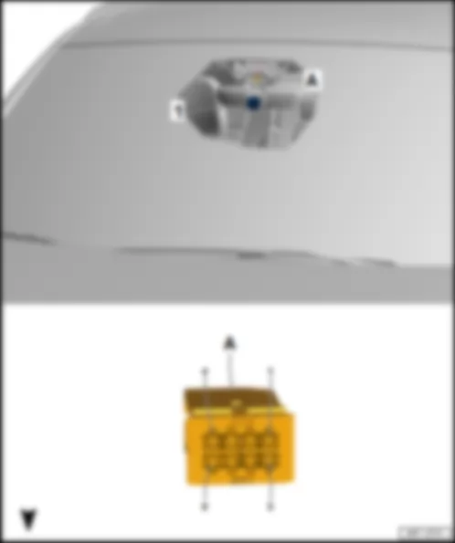
AUDI R8 2017
Fitting location, door control unit -J386- /-J387- |
| In driver door/front passenger door. |
| 1 - | Driver door control unit -J386- /front passenger door control unit -J387- |
| 6-pin connector -T6m- /-T6n- , black |
| q | Driver door control unit -J386- : -T6m- |
| q | Front passenger door control unit -J387- : -T6n- |
| 20-pin connector -T20b- /-T20c- , black |
| q | Driver door control unit -J386- : -T20b- |
| q | Front passenger door control unit -J387- : -T20c- |
| 16-pin connector -T16g- /-T16h- , black |
| q | Driver door control unit -J386- : -T16g- |
| q | Front passenger door control unit -J387- : -T16h- |
| 32-pin connector -T32h- /-T32i- , blue |
| q | Driver door control unit -J386- : -T32h- |
| q | Front passenger door control unit -J387- : -T32i- |
| Connector assignment, driver door control unit -J386- |
| -T6m- (A) | Designation | | -T20b- (B) | Designation |
| 1 | | | 1 | Contact switch in driver side locking cylinder -F241- in driver side locking unit for central locking -F220- |
| 2 | | | 2 | Microswitch for lowering driver window -E621- |
| 3 | Driver side window regulator motor -V147- | | 3 | |
| 4 | | | 4 | |
| 5 | | | 5 | Driver door contact switch -F2- in driver side locking unit for central locking -F220- |
| 6 | Driver side window regulator motor -V147- | | 6 | Front left central locking actuator -F131- in driver side locking unit for central locking -F220- |
| | | | 7 | |
| | | | 8 | Mirror dimming signal line, to B427 connection 1 (mirror signal) in main wiring harness |
| | | | 9 | |
| | | | 10 | |
| | | | 11 | Motor for central locking SAFE function in driver door -V161- /driver side motor for central locking -V503- in driver side locking unit for central locking -F220- |
| | | | 12 | Motor for central locking SAFE function in driver door -V161- in driver side locking unit for central locking -F220- |
| | | | 13 | Driver side motor for central locking -V503- in driver side locking unit for central locking -F220- |
| | | | 14 | Comfort low CAN bus to B406 connection 1 (comfort low CAN bus) in main wiring harness |
| | | | 15 | Comfort high CAN bus, to B397 connection 1 (comfort high CAN bus) in main wiring harness |
| | | | 16 | |
| | | | 17 | Mirror dimming signal line, to B428 connection 2 (mirror signal) in main wiring harness |
| | | | 18 | |
| | | | 19 | Terminal 30, from fuse carrier 5 -ST5- in fuse holder C -SC- |
| | | | 20 | Terminal 31, to 639 earth point on left A-pillar |
| -T16g- (C) | Designation | | -T32h- (D) | Designation |
| 1 | | | 1 | Central locking SAFELOCK function warning lamp -K133- |
| 2 | Driver side automatic anti-dazzle exterior mirror -Y20- | | 2 | |
| 3 | Earth line, to 107 earth connection in exterior mirror wiring harness | | 3 | Driver side door interior handle illumination bulb -L146- |
| 4 | | | 4 | Switch lights, to R95 connection 2 in driver door wiring harness |
| 5 | Earth supply for driver side mirror adjustment motors | | 5 | Earth line, to 205 earth connection in driver door wiring harness |
| 6 | Driver side automatic anti-dazzle exterior mirror -Y20- | | 6 | |
| 7 | Driver side mirror adjustment motor -V149- | | 7 | |
| 8 | Driver side mirror adjustment motor -V17- | | 8 | |
| 9 | Driver side fold-in mirror motor -V121- | | 9 | |
| 10 | Driver side fold-in mirror motor -V121- | | 10 | Alarm system off switch -E217- |
| 11 | Driver side turn signal repeater bulb in exterior mirror -L131- | | 11 | |
| 12 | | | 12 | |
| 13 | | | 13 | Driver side interior locking button for central locking system -E308- |
| 14 | | | 14 | |
| 15 | Heated exterior mirror on driver side -Z4- | | 15 | |
| 16 | | | 16 | Terminal 58, to R65 positive connection (58) in driver door wiring harness |
| | | | 17 | |
| | | | 18 | |
| | | | 19 | |
| | | | 20 | Alarm system off switch -E217- |
| | | | 21 | |
| | | | 22 | |
| | | | 23 | Rear lid remote release button -E233- |
| | | | 24 | Mirror adjustment switch -E43- |
| | | | 25 | Mirror adjustment changeover switch -E48- |
| | | | 26 | |
| | | | 27 | |
| | | | 28 | Driver side interior locking button for central locking system -E308- |
| | | | 29 | |
| | | | 30 | |
| | | | 31 | Front right window regulator switch in driver door -E81- in window regulator operating unit in driver door -E512- |
| | | | 32 | Front left window regulator switch -E40- in window regulator operating unit in driver door -E512- |
| Connector assignment, front passenger door control unit -J387- |
| -T6n- (A) | Designation | | -T20c- (B) | Designation |
| 1 | | | 1 | |
| 2 | | | 2 | Microswitch for lowering front passenger window -E622- |
| 3 | Front passenger side window regulator motor -V148- | | 3 | |
| 4 | | | 4 | |
| 5 | | | 5 | Front passenger door contact switch -F3- in front passenger side locking unit for central locking -F221- |
| 6 | Front passenger side window regulator motor -V148- | | 6 | Front right central locking actuator -F133- in front passenger side locking unit for central locking -F221- |
| | | | 7 | |
| | | | 8 | Mirror dimming signal line, to B427 connection 1 (mirror signal) in main wiring harness |
| | | | 9 | |
| | | | 10 | |
| | | | 11 | Front passenger side motor for central locking -V504- in front passenger side locking unit for central locking -F221- |
| | | | 12 | Motor for central locking SAFE function in front passenger door -V162- in front passenger side locking unit for central locking -F221- |
| | | | 13 | Motor for central locking SAFE function in front passenger door -V162- /front passenger side motor for central locking -V504- in front passenger side locking unit for central locking -F221- |
| | | | 14 | Comfort low CAN bus to B407 connection 2 (comfort low CAN bus) in main wiring harness |
| | | | 15 | Comfort high CAN bus, to B398 connection 2 (comfort high CAN bus) in main wiring harness |
| | | | 16 | |
| | | | 17 | Mirror dimming signal line, to B428 connection 2 (mirror signal) in main wiring harness |
| | | | 18 | |
| | | | 19 | Terminal 30, from fuse carrier 5 -ST5- in fuse holder C -SC- |
| | | | 20 | Terminal 31, to 751 earth point 2 on right A-pillar |
| -T16h- (C) | Designation | | -T32i- (D) | Designation |
| 1 | | | 1 | |
| 2 | Front passenger side automatic anti-dazzle exterior mirror -Y21- | | 2 | |
| 3 | Earth line, to 107 earth connection in exterior mirror wiring harness | | 3 | Front passenger side door interior handle illumination bulb -L147- |
| 4 | | | 4 | Switch lights, to R99 connection 2 in front passenger door wiring harness |
| 5 | Earth supply for front passenger side mirror adjustment motor | | 5 | Earth line, to 268 earth connection 2 in front passenger door wiring harness |
| 6 | Front passenger side automatic anti-dazzle exterior mirror -Y21- | | 6 | |
| 7 | Front passenger side mirror adjustment motor -V150- | | 7 | |
| 8 | Front passenger side mirror adjustment motor -V25- | | 8 | |
| 9 | Front passenger side fold-in mirror motor -V122- | | 9 | |
| 10 | Front passenger side fold-in mirror motor -V122- | | 10 | |
| 11 | Front passenger side turn signal repeater bulb in exterior mirror -L132- | | 11 | |
| 12 | | | 12 | |
| 13 | | | 13 | Front passenger side interior locking button for central locking system -E309- |
| 14 | | | 14 | |
| 15 | Heated exterior mirror on front passenger side -Z5- | | 15 | |
| 16 | | | 16 | Terminal 58, to R67 positive connection (58) in front passenger door wiring harness |
| | | | 17 | |
| | | | 18 | |
| | | | 19 | |
| | | | 20 | |
| | | | 21 | |
| | | | 22 | |
| | | | 23 | |
| | | | 24 | |
| | | | 25 | |
| | | | 26 | |
| | | | 27 | |
| | | | 28 | Front passenger side interior locking button for central locking system -E309- |
| | | | 29 | |
| | | | 30 | |
| | | | 31 | |
| | | | 32 | Front passenger side window regulator button -E716- |
AUDI R8 2017 Fitting location, convenience system central control unit J393
Fitting location, convenience system central control unit -J393- |
| Under the rear shelf on the rear wall on the left next to the control unit 1 for information electronics -J794- . |
| 1 - | Convenience system central control unit -J393- |
| B - | 32-pin connector -T32e- , grey |
| D - | 17-pin connector -T17k- , black |
| F - | 17-pin connector -T17l- , brown |
| Connector assignment, convenience system central control unit -J393- |
| -T32f- (A) | Designation | | -T32e- (B) | Designation |
| 1 | | | 1 | |
| 2 | | | 2 | Brake light signal, from brake light switch -F- |
| 3 | | | 3 | |
| 4 | | | 4 | Front lid contact switch -F387- |
| 5 | | | 5 | Engine control unit -J623- |
| 6 | | | 6 | |
| 7 | | | 7 | |
| 8 | | | 8 | |
| 9 | Left aerial for entry and start authorisation -R200- | | 9 | |
| 10 | Left aerial for entry and start authorisation -R200- | | 10 | |
| 11 | Luggage compartment aerial for entry and start system -R137- | | 11 | |
| 12 | Luggage compartment aerial for entry and start system -R137- | | 12 | Steering column electronics control unit -J527- |
| 13 | Right aerial for entry and start authorisation -R201- | | 13 | Steering column electronics control unit -J527- |
| 14 | Right aerial for entry and start authorisation -R201- | | 14 | |
| 15 | Interior aerial 1 for entry and start system -R138- | | 15 | Control unit for electronic steering column lock -J764- |
| 16 | Interior aerial 1 for entry and start system -R138- | | 16 | Terminal 15 voltage supply relay -J329- |
| 17 | | | 17 | |
| 18 | | | 18 | Additional brake light bulb -M25- |
| 19 | | | 19 | Sequential indicator coding lead, to B474 connection 10 in main wiring harness |
| 20 | | | 20 | Steering column electronics control unit -J527- |
| 21 | | | 21 | |
| 22 | | | 22 | |
| 23 | | | 23 | |
| 24 | | | 24 | |
| 25 | | | 25 | |
| 26 | | | 26 | |
| 27 | | | 27 | |
| 28 | | | 28 | Selector position P/N line, from mechatronic unit for dual clutch gearbox -J743- |
| 29 | | | 29 | |
| 30 | Contact sensor for front right exterior door handle -G606- | | 30 | |
| 31 | | | 31 | |
| 32 | Contact sensor for front left exterior door handle -G605- | | 32 | |
| -T17k- (D) | Designation | | -T32d- (E) | Designation | | -T17l- (F) | Designation |
| 1 | | | 1 | | | 1 | |
| 2 | | | 2 | | | 2 | |
| 3 | | | 3 | Button for emergency luggage compartment release -E596- | | 3 | |
| 4 | | | 4 | Heated rear window relay -J9- | | 4 | |
| 5 | Suppression filter -C24- /front lid release motor -V394- | | 5 | | | 5 | Left reversing light bulb -M16- in left tail light module -MX3- |
| 6 | Tank filler flap locking motor -V155- | | 6 | | | 6 | Bulb 2 for left brake light -M86- in left tail light module -MX3- |
| 7 | Tank filler flap locking motor -V155- | | 7 | | | 7 | |
| 8 | Bulb for right brake light -M10- in right tail light module -MX4- | | 8 | | | 8 | Luggage compartment light -W3- |
| 9 | Bulb for right tail light -M2- in right tail light module -MX4- | | 9 | | | 9 | Left brake light bulb -M9- in left tail light module -MX3- |
| 10 | Right rear fog light bulb -L47- in right tail light module -MX4- | | 10 | | | 10 | Left tail light bulb -M4- in left tail light module -MX3- |
| 11 | Right reversing light bulb -M17- in right tail light module -MX4- | | 11 | | | 11 | Left rear fog light bulb -L46- in left tail light module -MX3- |
| 12 | Rear right direction indicator bulb -M8- in right tail light module -MX4- | | 12 | | | 12 | Bulb 2 for right brake light -M87- in right tail light module -MX4- |
| 13 | | | 13 | | | 13 | Rear left direction indicator bulb -M6- in left tail light module -MX3- |
| 14 | | | 14 | Number plate light -X4- /-X5- | | 14 | |
| 15 | Terminal 30, from fuse carrier 2 -ST2- in fuse holder D -SD- | | 15 | Relay for power sockets -J807- | | 15 | Control unit for electronic steering column lock -J764- |
| 16 | Terminal 30, from fuse carrier 2 -ST2- in fuse holder D -SD- | | 16 | Alarm horn -H12- | | 16 | Terminal 30, from fuse carrier 2 -ST2- in fuse holder D -SD- |
| 17 | Terminal 31, to 35 earth point under front passenger seat | | 17 | LIN bus, to B698 connection 3 (LIN bus) in main wiring harness | | 17 | Terminal 31, to 758 earth point 3 on centre tunnel |
| | | | 18 | Comfort low CAN bus to B406 connection 1 (comfort low CAN bus) in main wiring harness | | | |
| | | | 19 | Comfort high CAN bus, to B397 connection 1 (comfort high CAN bus) in main wiring harness | | | |
| | | | 20 | | | | |
| | | | 21 | | | | |
| | | | 22 | | | | |
| | | | 23 | | | | |
| | | | 24 | | | | |
| | | | 25 | | | | |
| | | | 26 | | | | |
| | | | 27 | | | | |
| | | | 28 | | | | |
| | | | 29 | | | | |
| | | | 30 | Rear right side marker bulb -M38- | | | |
| | | | 31 | Rear left side marker bulb -M37- | | | |
| | | | 32 | LIN bus, to B699 connection 4 (LIN bus) in main wiring harness | | | |
AUDI R8 2017 Fitting location, headlight range control unit J431
Fitting location, headlight range control unit -J431- |
| In the footwell on the front passenger side on the wheel housing under the carpet |
| 1 - | Headlight range control unit -J431- |
| Connector assignment, headlight range control unit -J431- |
| -T26a- (A) | Designation | | -T26a- (A) | Designation |
| 1 | | | 14 | |
| 2 | Extended CAN bus high, to B108 connection 1 (extended CAN bus high) in main wiring harness1) /
to data bus diagnostic interface -J533-2) | | 15 | |
| 3 | Extended CAN bus low, to B109 connection 1 (extended CAN bus low) in main wiring harness1) /
to data bus diagnostic interface -J533-2) | | 16 | |
| 4 | CAN bus low, to front headlight -MX1- /-MX2- | | 17 | |
| 5 | CAN bus high, to front headlight -MX1- /-MX2- | | 18 | |
| 6 | | | 19 | |
| 7 | | | 20 | |
| 8 | | | 21 | |
| 9 | | | 22 | |
| 10 | | | 23 | Terminal 15, from fuse carrier 1 -ST1- in fuse holder C -SC- |
| 11 | | | 24 | Terminal 31, to 751 earth point 2 on right A-pillar |
| 12 | | | 25 | |
| 13 | | | 26 | |
| 1) Models with main beam assist control unit -J844- |
| 2) Models without main beam assist control unit -J844- |
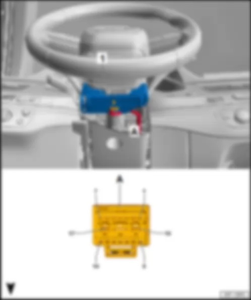
AUDI R8 2017 Fitting location, multifunction steering wheel control unit J453
Fitting location, multifunction steering wheel control unit -J453- |
| Integrated on the steering wheel on the left in the damping adjustment button -E387- . |
| 1 - | Multifunction steering wheel control unit -J453- |
| q | integrated in damping adjustment button -E387- |
| B - | 12-pin connector -T12q- , black |
| q | to multifunction buttons on the left in the steering wheel -E440- |
| D - | 4-pin connector -T4da- , black |
| q | to entry and start authorisation button -E408- |
| Connector assignment, multifunction steering wheel control unit -J453- | | | |
| -T6ag- (C) | Designation |
| 1 | LIN bus, from spring -F350- |
| 2 | Terminal 30, from spring -F350- |
| 3 | Terminal 31, from spring -F350- |
| 4 | Horn plate -H- |
| 5 | Tiptronic switch, to spring -F350- |
| 6 | Tiptronic switch, to spring -F350- |
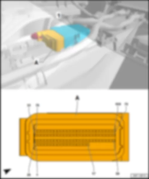
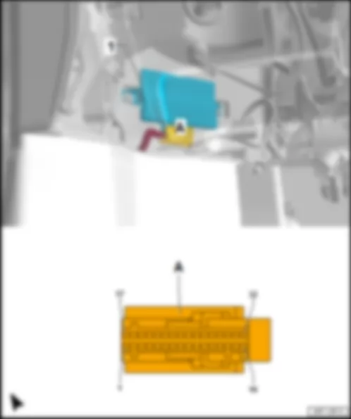
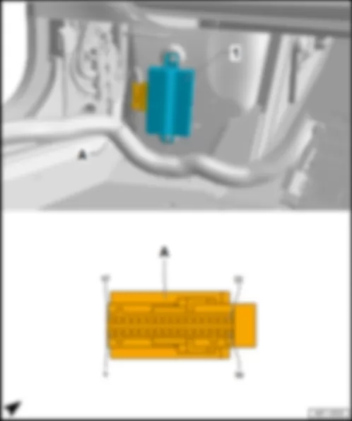
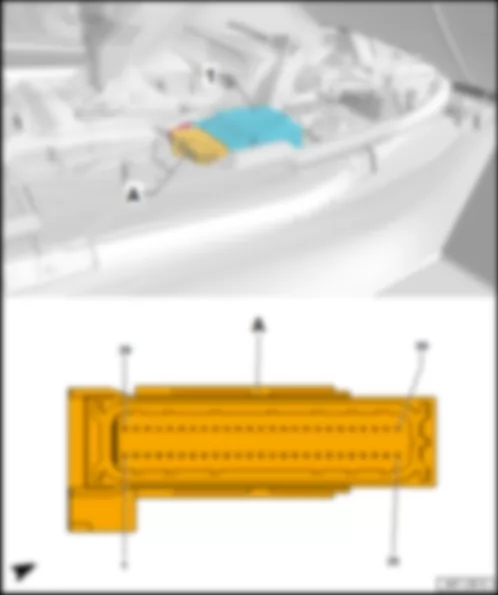
AUDI R8 2017 Fitting location, onboard supply control unit J519
Fitting location, onboard supply control unit -J519- |
| In the footwell on the front passenger side above the relay and fuse carrier 3 -SR3- . |
| 1 - | Onboard supply control unit -J519- |
| B - | 17-pin connector -T17e- , red |
| D - | 17-pin connector -T17g- , black |
| F - | 32-pin connector -T32b- , grey |
| Connector assignment, onboard supply control unit -J519- |
| -T16e- (A) | Designation | | -T17e- (B) | Designation | | -T17f- (C) | Designation |
| 1 | | | 1 | | | 1 | |
| 2 | LIN bus, to B711 connection 6 (LIN bus) in main wiring harness | | 2 | Front right headlight -MX2- | | 2 | Front left headlight -MX1- |
| 3 | Positive supply for front parking aid sender, to X65 connection (parking aid) in front bumper wiring harness | | 3 | | | 3 | |
| 4 | LIN bus, to B549 connection 2 (LIN bus) in main wiring harness | | 4 | Front right headlight -MX2- | | 4 | Front right side marker bulb -M34- |
| 5 | Earth supply for front and rear parking aid senders, to B468 connection 4 in main wiring harness | | 5 | Front left headlight -MX1- | | 5 | Front left headlight -MX1- |
| 6 | LIN bus, to B710 connection 5 (LIN bus) in main wiring harness | | 6 | | | 6 | Front left side marker bulb -M33- |
| 7 | | | 7 | Front left headlight -MX1- | | 7 | |
| 8 | | | 8 | Front right headlight -MX2- | | 8 | Front left headlight -MX1- |
| 9 | | | 9 | | | 9 | |
| 10 | | | 10 | Front right headlight -MX2- | | 10 | |
| 11 | | | 11 | | | 11 | |
| 12 | | | 12 | Front right headlight -MX2- | | 12 | Front left headlight -MX1- |
| 13 | | | 13 | | | 13 | |
| 14 | Comfort low CAN bus to B407 connection 2 (comfort low CAN bus) in main wiring harness | | 14 | Front right headlight -MX2- | | 14 | |
| 15 | Comfort high CAN bus, to B398 connection 2 (comfort high CAN bus) in main wiring harness | | 15 | Front right headlight -MX2- | | 15 | Front left headlight -MX1- |
| 16 | | | 16 | Terminal 30, from fuse carrier 5 -ST5- in fuse holder C -SC- | | 16 | Terminal 30, from fuse carrier 5 -ST5- in fuse holder C -SC- |
| | | | 17 | Terminal 31, to 645 earth point 1 on bulkhead | | 17 | Terminal 31, to 751 earth point 2 on right A-pillar |
| -T17g- (D) | Designation | | -T17g- (D) | Designation | | -T6f- (E) | Designation |
| 1 | | | 10 | Air conditioner compressor regulating valve -N280- | | 1 | Positive supply for driver seat heating, to O12 connection 1 in seat heating wiring harness |
| 2 | | | 11 | | | 2 | |
| 3 | Washer pump -V5- | | 12 | | | 3 | Terminal 30, from fuse carrier 5 -ST5- in fuse holder C -SC- |
| 4 | Washer pump -V5- | | 13 | | | 4 | |
| 5 | | | 14 | Positive supply for engine compartment light -W108- /-W109- | | 5 | |
| 6 | | | 15 | Terminal 30, from fuse carrier 5 -ST5- in fuse holder C -SC- | | 6 | Positive supply for front passenger seat heating, to O13 connection 2 in seat heating wiring harness |
| 7 | | | 16 | Terminal 30, from fuse carrier 5 -ST5- in fuse holder C -SC- | | | |
| 8 | Air conditioner compressor regulating valve -N280- | | 17 | Terminal 30 (output), to B485 connection 21 in main wiring harness | | | |
| 9 | Roof electronics control unit -J528- | | | | | | |
| -T32b- (F) | Designation | | -T32a- (G) | Designation |
| 1 | Parking aid button -E266- in switch module in centre of dash panel -EX22- | | 1 | Terminal 58s, to B732 connection 2 (58s) in main wiring harness |
| 2 | Parking aid warning lamp -K136- in switch module in centre of dash panel -EX22- | | 2 | Positive supply for rear parking aid sender, to X68 connection (parking aid) in rear bumper wiring harness |
| 3 | | | 3 | Bonnet contact switch -F266- /-F329- |
| 4 | | | 4 | Rear parking aid warning buzzer -H15- |
| 5 | | | 5 | |
| 6 | Front parking aid warning buzzer -H22- | | 6 | Brake fluid level warning contact -F34- |
| 7 | Front parking aid warning buzzer -H22- | | 7 | Rear parking aid warning buzzer -H15- |
| 8 | Warning lamp button -E229- in switch module in centre of dash panel -EX22- | | 8 | |
| 9 | Light switch -E1- | | 9 | Front left brake pad wear sender -G34- or front right brake pad wear sender -G35- , depending on equipment |
| 10 | | | 10 | Ambient temperature sensor -G17- |
| 11 | | | 11 | Rear left parking aid sender -G203- |
| 12 | | | 12 | Rear centre left parking aid sender -G204- |
| 13 | | | 13 | |
| 14 | | | 14 | Front left seat temperature sender -G344- |
| 15 | | | 15 | Rear centre right parking aid sender -G205- |
| 16 | | | 16 | Terminal 15, from fuse carrier 1 -ST1- in fuse holder C -SC- |
| 17 | Positive supply for light -L231- /-W9- /-W10- | | 17 | Terminal 58s, to B731 connection 1 (58s) in main wiring harness |
| 18 | Light switch -E1- | | 18 | Rear right parking aid sender -G206- |
| 19 | | | 19 | Front right seat temperature sender -G345- |
| 20 | | | 20 | |
| 21 | | | 21 | |
| 22 | | | 22 | |
| 23 | | | 23 | Front left parking aid sender -G255- |
| 24 | Start/stop operation warning lamp -K259- in switch module in centre of dash panel -EX22- | | 24 | Heating resistor for spray nozzle -Z20- /-Z21- |
| 25 | | | 25 | Earth line, to 410 earth connection 1 (sender earth) in main wiring harness |
| 26 | Control unit for electronic steering column lock -J764- | | 26 | Front centre left parking aid sender -G254- |
| 27 | | | 27 | Coolant shortage indicator sender -G32- |
| 28 | Hazard warning lights warning lamp -K6- in switch module in centre of dash panel -EX22- | | 28 | Windscreen washer fluid level sender -G33- |
| 29 | | | 29 | Horn relay -J413- |
| 30 | Start/stop operation button -E693- in switch module in centre of dash panel -EX22- | | 30 | Front centre right parking aid sender -G253- |
| 31 | Terminal 58s, to A175 connection (58s) in dash panel wiring harness | | 31 | Front right parking aid sender -G252- |
| 32 | | | 32 | |
AUDI R8 2017 Fitting location, digital sound package control unit J525
Fitting location, digital sound package control unit -J525- |
| Under the rear shelf on the rear wall on the outer left. |
| 1 - | Digital sound package control unit -J525- |
| C - | 2-pin connector -T2ff- , black |
| Connector assignment, digital sound package control unit -J525- |
| -T38a- (A) | Designation | | -T38a- (A) | Designation | | -T38a- (A) | Designation |
| 1 | Terminal 30, from fuse carrier 6 -ST6- in fuse holder C -SC- | | 14 | Front right mid-range loudspeaker -R104- | | 27 | |
| 2 | Terminal 31, to 688 earth point 2 on centre tunnel | | 15 | | | 28 | Centre loudspeaker 2 -R219- |
| 3 | | | 16 | Rear right mid-range loudspeaker -R106- | | 29 | Internal microphone -R74- |
| 4 | Rear left mid-range loudspeaker -R105- | | 17 | Rear right mid-range loudspeaker -R106- | | 30 | |
| 5 | Rear left mid-range loudspeaker -R105- | | 18 | Centre loudspeaker -R208- | | 31 | Front right treble loudspeaker -R22- |
| 6 | Centre loudspeaker -R208- | | 19 | Front right bass loudspeaker -R23- | | 32 | Front left treble loudspeaker -R20- |
| 7 | Front left bass loudspeaker -R21- | | 20 | Front right bass loudspeaker -R23- | | 33 | Rear left treble loudspeaker -R14- |
| 8 | Front left bass loudspeaker -R21- | | 21 | | | 34 | Rear right treble loudspeaker -R16- |
| 9 | Subwoofer -R211- | | 22 | | | 35 | |
| 10 | Subwoofer -R211- | | 23 | Front right treble loudspeaker -R22- | | 36 | Centre loudspeaker 2 -R219- |
| 11 | Front left mid-range loudspeaker -R103- | | 24 | Front left treble loudspeaker -R20- | | 37 | Internal microphone -R74- |
| 12 | Front left mid-range loudspeaker -R103- | | 25 | Rear left treble loudspeaker -R14- | | 38 | Ring break diagnosis, to B444 connection 1 (diagnosis) in main wiring harness |
| 13 | Front right mid-range loudspeaker -R104- | | 26 | Rear right treble loudspeaker -R16- | | | |
AUDI R8 2017 Fitting location, steering column electronics control unit J527
Fitting location, steering column electronics control unit -J527- |
| 1 - | Steering column electronics control unit -J527- |
| Connector assignment, steering column electronics control unit -J527- |
| -T17d- (A) | Designation | | -T17d- (A) | Designation |
| 1 | Terminal 30, from fuse carrier 4 -ST4- in fuse holder C -SC- | | 10 | Convenience system central control unit -J393- |
| 2 | Terminal 15, from fuse carrier 1 -ST1- in fuse holder C -SC- | | 11 | Airbag control unit -J234- |
| 3 | Running gear sensors CAN bus high, to B663 connection (running gear sensors CAN bus high) in main wiring harness | | 12 | Airbag control unit -J234- |
| 4 | Running gear sensors CAN bus low, to B664 connection (running gear sensors CAN bus low) in main wiring harness | | 13 | |
| 5 | Dash panel insert CAN bus low, to B709 connection 1 (dash panel insert CAN bus low) in main wiring harness | | 14 | |
| 6 | Dash panel insert CAN bus high, to B708 connection 1 (dash panel insert CAN bus high) in main wiring harness | | 15 | Automatic gearbox control unit 2 -J1006- |
| 7 | Engine control unit -J623- | | 16 | Automatic gearbox control unit 2 -J1006- |
| 8 | Convenience system central control unit -J393- | | 17 | Terminal 31, to 687 earth point 1 on centre tunnel |
| 9 | Convenience system central control unit -J393- | | | |
AUDI R8 2017 Fitting location, roof electronics control unit J528
Fitting location, roof electronics control unit -J528- |
| In front roof module -WX3- . |
| 1 - | Roof electronics control unit -J528- |
| B - | 3-pin connector -T3d- , black |
| q | for garage door operating unit -E284- |
| D - | 12-pin connector -T12g- , black |
| q | for roof electronics control unit -J528- |
| Connector assignment of roof electronics control unit -J528- |
| -T12g- (A) | Designation | | -T12g- (A) | Designation |
| 1 | | | 7 | Automatic anti-dazzle interior mirror -Y7- |
| 2 | | | 8 | Terminal 30, from fuse carrier 4 -ST4- in fuse holder C -SC- |
| 3 | | | 9 | Onboard supply control unit -J519- |
| 4 | Terminal 15, from fuse carrier 1 -ST1- in fuse holder C -SC- | | 10 | Terminal 31, to 689 earth point, at front, central in roof |
| 5 | | | 11 | Terminal 58s, to B732 connection 2 (58s) in main wiring harness |
| 6 | Airbag control unit -J234- | | 12 | Terminal 30, from B485 connection 21 in main wiring harness |
AUDI R8 2017 Fitting location, data bus diagnostic interface J533Fitting location, data bus diagnostic interface -J533- |
| | |
| Fitting location Data bus diagnostic interface -J533- , left-hand drive models |
| In the footwell on the driver side on the top of the wheel housing behind the dash panel. |
| 1 - | Data bus diagnostic interface -J533- |
| Connector assignment, data bus diagnostic interface -J533- |
| -T32c- (A) | Designation | | -T32c- (A) | Designation |
| 1 | | | 17 | LIN bus, to B528 connection 1 (LIN bus) in main wiring harness |
| 2 | Extended CAN bus low, to B109 connection 1 (extended CAN bus low) in main wiring harness1) /
to headlight range control unit -J431-2) | | 18 | Extended CAN bus high, to B108 connection 1 (extended CAN bus high) in main wiring harness1) /
to headlight range control unit -J431-2) |
| 3 | Diagnostic low CAN bus, to diagnostic connection -U31- | | 19 | Diagnostic high CAN bus, to diagnostic connection -U31- |
| 4 | Comfort low CAN bus to B406 connection 1 (comfort low CAN bus) in main wiring harness | | 20 | Comfort high CAN bus, to B397 connection 1 (comfort high CAN bus) in main wiring harness |
| 5 | Drive low CAN bus, to B391 connection 2 (drive low CAN bus) in main wiring harness | | 21 | Drive high CAN bus to B384 connection 2 (drive high CAN bus) in main wiring harness |
| 6 | Dash panel insert CAN bus low, to B709 connection 1 (dash panel insert CAN bus low) in main wiring harness | | 22 | Dash panel insert CAN bus high, to B708 connection 1 (dash panel insert CAN bus high) in main wiring harness |
| 7 | FlexRay bus, to ABS control unit -J104- | | 23 | FlexRay bus, to ABS control unit -J104- |
| 8 | | | 24 | |
| 9 | | | 25 | |
| 10 | FlexRay bus, to control unit for sensor electronics -J849- | | 26 | FlexRay bus, to control unit for sensor electronics -J849- |
| 11 | | | 27 | |
| 12 | | | 28 | |
| 13 | Terminal 31, to 639 earth point on left A-pillar | | 29 | Terminal 31, to 639 earth point on left A-pillar |
| 14 | Terminal 15, from fuse carrier 1 -ST1- in fuse holder C -SC- | | 30 | |
| 15 | Running gear sensors CAN bus low, to B664 connection (running gear sensors CAN bus low) in main wiring harness | | 31 | Running gear sensors CAN bus high, to B663 connection (running gear sensors CAN bus high) in main wiring harness |
| 16 | Terminal 30, from fuse carrier 3 -ST3- in fuse holder C -SC- | | 32 | |
| 1) Models with main beam assist control unit -J844- |
| 2) Models without main beam assist control unit -J844- |
| Fitting location Data bus diagnostic interface -J533- , right-hand drive models |
| In the footwell on the front passenger side, at the bottom of the wheel housing under the carpet |
| 1 - | Data bus diagnostic interface -J533- |
| A - | 32-pin connector -T32c- , black |
AUDI R8 2017 Fitting location, selector lever sensors control unit J587
Fitting location, selector lever sensors control unit -J587- |
| In selector lever -E313- in centre console. |
| 1 - | Selector lever sensors control unit -J587- |
| q | in selector lever -E313- |
| Connector assignment, selector lever sensors control unit -J587- |
| -T10d- (A) | Designation | | -T10d- (A) | Designation |
| 1 | Terminal 30, from fuse carrier 4 -ST4- in fuse holder C -SC- | | 6 | |
| 2 | | | 7 | |
| 3 | Drive low CAN bus, to B391 connection 2 (drive low CAN bus) in main wiring harness | | 8 | |
| 4 | Drive high CAN bus to B384 connection 2 (drive high CAN bus) in main wiring harness | | 9 | |
| 5 | | | 10 | Terminal 31, to 687 earth point 1 on centre tunnel |
AUDI R8 2017 Fitting location, chip card reader control unit J676
Fitting location, chip card reader control unit -J676- |
| At the top of the glove compartment. |
| 1 - | Chip card reader control unit -J676- |
| B - | 10-pin connector -T10k- , black |
| Connector assignment, chip card reader control unit -J676- |
| -T10k- (A) | Designation | | -T10k- (A) | Designation |
| 1 | Traffic data aerial -R173- | | 6 | Control unit 1 for information electronics -J794- |
| 2 | Traffic data aerial -R173- | | 7 | Traffic data aerial -R173- |
| 3 | Traffic data aerial -R173- | | 8 | Traffic data aerial -R173- |
| 4 | Traffic data aerial -R173- | | 9 | Terminal 30, from fuse carrier 6 -ST6- in fuse holder C -SC- |
| 5 | | | 10 | Terminal 31, to 638 earth point on right A-pillar |
AUDI R8 2017 Fitting location, seat occupied recognition control unit J706
Fitting location, seat occupied recognition control unit -J706- |
| On front passenger side at the bottom. |
| 1 - | Seat occupied recognition control unit -J706- |
| q | To sensor pad in front passenger seat |
| Connector assignment, seat occupied recognition control unit -J706- |
| | | -T3bi- (B) | Designation |
| 1 | Terminal 15, from fuse carrier 1 -ST1- in fuse holder C -SC- |
| 2 | Airbag control unit -J234- |
| 3 | Terminal 31 to 471 earth connection 5 in seat adjustment wiring harness |
AUDI R8 2017 Fitting location, control unit for electronic steering column lock J764
Fitting location, control unit for electronic steering column lock -J764- |
| On top of the steering column. |
| 1 - | Control unit for electronic steering column lock -J764- |
| Connector assignment of control unit for electronic steering column lock -J764- |
| | | -T6s- (A) | Designation |
| 1 | Convenience system central control unit -J393- |
| 2 | Onboard supply control unit -J519- |
| 3 | Terminal 31, to 664 earth point on left behind dash panel |
| 4 | Convenience system central control unit -J393- |
| 5 | LIN bus, to B698 connection 3 (LIN bus) in main wiring harness |
| 6 | Terminal 30, from fuse carrier 3 -ST3- in fuse holder C -SC- |
AUDI R8 2017 Fitting location Reversing camera system control unit J772
Fitting location Reversing camera system control unit -J772- |
| Under the rear shelf at the bottom outer right on the rear wall. |
| 1 - | Reversing camera system control unit -J772- |
| B - | 2-pin connector -T2bs- , green |
| q | to control unit for information electronics 1 -J794- |
| Connector assignment, reversing camera system control unit -J772- |
| -T20a- (C) | Designation | | -T20a- (C) | Designation |
| 1 | | | 11 | Dash panel insert CAN bus low, to B709 connection 1 (dash panel insert CAN bus low) in main wiring harness |
| 2 | | | 12 | Dash panel insert CAN bus high, to B708 connection 1 (dash panel insert CAN bus high) in main wiring harness |
| 3 | | | 13 | |
| 4 | | | 14 | |
| 5 | | | 15 | |
| 6 | | | 16 | |
| 7 | | | 17 | |
| 8 | | | 18 | |
| 9 | Reversing camera -R189- | | 19 | Reversing camera -R189- |
| 10 | Terminal 30, from fuse carrier 6 -ST6- in fuse holder C -SC- | | 20 | Terminal 31, to 35 earth point under front passenger seat |
AUDI R8 2017 Fitting location, active steering control unit J792
Fitting location, active steering control unit -J792- |
| On the left on the steering column, behind the dash panel. |
| 1 - | Active steering control unit -J792- |
| B - | 8-pin connector -T8n- , black |
| Connector assignment, active steering control unit -J792- |
| -T10i- (A) | Designation | | -T8n- (B) | Designation | | -T5f- (C) | Designation |
| 1 | Active steering safety lock actuator -F437- | | 1 | | | 1 | Active steering motor -V477- |
| 2 | Active steering safety lock actuator -F437- | | 2 | Terminal 15, from fuse carrier 1 -ST1- in fuse holder C -SC- | | 2 | Active steering motor -V477- |
| 3 | Running gear sensors CAN bus low, to B664 connection (running gear sensors CAN bus low) in main wiring harness | | 3 | Signal from position sensor 4 | | 3 | Active steering motor -V477- |
| 4 | Running gear sensors CAN bus high, to B663 connection (running gear sensors CAN bus high) in main wiring harness | | 4 | Signal from position sensor 3 | | 4 | Terminal 31, to 670 earth point 2 on left A-pillar |
| 5 | | | 5 | Signal from position sensor 2 | | 5 | Terminal 30, from fuse 3 (30) -S206- on cover of main fuse carrier |
| 6 | | | 6 | Signal from position sensor 1 | | | |
| 7 | | | 7 | Earth supply for position sensors | | | |
| 8 | | | 8 | Positive supply for position sensors | | | |
| 9 | | | | | | | |
| 10 | | | | | | | |
AUDI R8 2017 Fitting location, control unit 1 for information electronics J794
Fitting location, control unit 1 for information electronics -J794- |
| Under the rear shelf in the centre of the rear wall. |
| 1 - | Control unit 1 for information electronics -J794- |
| B - | C - | 8-pin connector -T8h- , black |
| E - | 12-pin connector -T12k- , green |
| G - | 8-pin connector -T8g- , brown |
| J - | 5-pin connector -T5v- , yellow |
| q | to connection for external audio sources -R199- |
| L - | 4-pin connector -T4z- , white |
| q | AM/FM aerial connection from aerial amplifier -R24- for aerial -R11- |
| q | FM2 aerial connection from aerial amplifier 2 -R111- for radio aerial 2 -R93- |
| Connector assignment, control unit 1 for information electronics -J794- |
| -T8h- (C) | Designation | | -T12i- (D) | Designation | | -T12k- (E) | Designation |
| 9 | | | 1 | CAN bus, control unit 1 for information electronics, high, to E145 connection 1 (CAN bus, control unit 1 for information electronics, high) | | 1 | Connection for external audio sources -R199- , AUX IN earth |
| 10 | Centre loudspeaker -R208-1) | | 2 | Multimedia system operating unit -E380- | | 2 | Connection for external audio sources -R199- , AUX IN right |
| 11 | | | 3 | Ring break diagnosis, to B444 connection 1 (diagnosis) in main wiring harness | | 3 | Connection for external audio sources -R199- , USB earth |
| 12 | | | 4 | | | 4 | |
| 13 | | | 5 | Chip card reader control unit -J676- /aerial amplifier for mobile telephone -R86- /telephone bracket -R126- | | 5 | |
| 14 | Centre loudspeaker -R208-1) | | 6 | Dash panel insert CAN bus high, to A204 connection (dash panel insert CAN bus high) in dash panel wiring harness | | 6 | |
| 17 | Terminal 31, to 688 earth point 2 on centre tunnel | | 7 | CAN bus, control unit 1 for information electronics, low, to E147 connection 1 (CAN bus, control unit 1 for information electronics, low) | | 7 | Connection for external audio sources -R199- , AUX IN left |
| 18 | Terminal 30, from fuse carrier 6 -ST6- in fuse holder C -SC- | | 8 | Multimedia system operating unit -E380- | | 8 | Connection for external audio sources -R199- , screen earth |
| | | | 9 | | | 9 | |
| | | | 10 | | | 10 | |
| | | | 11 | Telephone bracket -R126- | | 11 | |
| | | | 12 | Dash panel insert CAN bus low, to A205 connection (dash panel insert CAN bus low) in dash panel wiring harness | | 12 | |
| 1) Only models without digital sound package control unit -J525- |
| -T12h- (F) | Designation | | -T8g- (G) | Designation |
| 1 | Control unit for seat belt microphone -J886- | | 1 | Front right treble loudspeaker -R22-1) |
| 2 | Control unit for seat belt microphone -J886- | | 2 | Front right bass loudspeaker -R23-1) |
| 3 | | | 3 | Front left bass loudspeaker -R21-1) |
| 4 | | | 4 | Front left treble loudspeaker -R20-1) |
| 5 | | | 5 | Front right treble loudspeaker -R22-1) |
| 6 | Reversing camera system control unit -J772- | | 6 | Front right bass loudspeaker -R23-1) |
| 7 | Control unit for seat belt microphone -J886- | | 7 | Front left bass loudspeaker -R21-1) |
| 8 | Control unit for seat belt microphone -J886- | | 8 | Front left treble loudspeaker -R20-1) |
| 9 | | | | |
| 10 | | | | |
| 11 | | | | |
| 12 | Reversing camera system control unit -J772- | | | |
| 1) Only models without digital sound package control unit -J525- |
AUDI R8 2017 Fitting location, interface control unit for vehicle location system J843
Fitting location, interface control unit for vehicle location system -J843- |
| In the footwell on the front passenger side above the onboard supply control unit -J519- . |
| 1 - | Interface control unit for vehicle location system -J843- |
| A - | 12-pin connector -T12- |
| B - | 12-pin connector -T12b- , brown |
| C - | 20-pin connector -T20- |
| Connector assignment, interface control unit for vehicle location system -J843- |
| -T12b- (B) | Designation | | -T12b- (B) | Designation |
| 1 | | | 7 | Comfort high CAN bus, to B398 connection 2 (comfort high CAN bus) in main wiring harness |
| 2 | | | 8 | Comfort low CAN bus to B407 connection 2 (comfort low CAN bus) in main wiring harness |
| 3 | Terminal 30, from fuse carrier 5 -ST5- in fuse holder C -SC- | | 9 | |
| 4 | | | 10 | |
| 5 | | | 11 | |
| 6 | Terminal 31, to 751 earth point 2 on right A-pillar | | 12 | |
AUDI R8 2017 Fitting location Main beam assist control unit J844
Fitting location Main beam assist control unit -J844- |
| 1 - | Main beam assist control unit -J844- |
| Connector assignment of main beam assist control unit -J844- |
| -T8b- (A) | Designation | | -T8b- (A) | Designation |
| 1 | Terminal 15, from fuse carrier 1 -ST1- in fuse holder C -SC- | | 5 | Mirror dimming signal line, to B428 connection 2 (mirror signal) in main wiring harness |
| 2 | Terminal 31, to 689 earth point, at front, central in roof | | 6 | Roof electronics control unit -J528- |
| 3 | Extended high CAN bus, to B108 connection 1 (extended high CAN bus) in main wiring harness | | 7 | |
| 4 | Mirror dimming signal line, to B427 connection 1 (mirror signal) in main wiring harness | | 8 | Extended CAN bus low, from B109 connection 1 (extended CAN bus low) in main wiring harness |
AUDI R8 2017 Fitting location, control unit for sensor electronics J849
Fitting location, control unit for sensor electronics -J849- |
| Under the centre console at the front on the centre tunnel behind the airbag control unit -J234- . |
| 1 - | Control unit for sensor electronics -J849- |
| Connector assignment, control unit for sensor electronics -J849- |
| -T50a- (A) | Designation | | -T50a- (A) | Designation |
| 1 | | | 26 | Terminal 31, to 687 earth point 1 on centre tunnel |
| 2 | | | 27 | |
| 3 | Terminal 15, from fuse carrier 1 -ST1- in fuse holder C -SC- | | 28 | |
| 4 | | | 29 | |
| 5 | | | 30 | |
| 6 | | | 31 | |
| 7 | | | 32 | |
| 8 | | | 33 | |
| 9 | | | 34 | |
| 10 | | | 35 | |
| 11 | | | 36 | |
| 12 | | | 37 | |
| 13 | | | 38 | |
| 14 | | | 39 | |
| 15 | | | 40 | |
| 16 | | | 41 | |
| 17 | | | 42 | |
| 18 | | | 43 | |
| 19 | FlexRay bus, from data bus diagnostic interface -J533- | | 44 | |
| 20 | FlexRay bus, from data bus diagnostic interface -J533- | | 45 | |
| 21 | | | 46 | |
| 22 | | | 47 | |
| 23 | | | 48 | |
| 24 | | | 49 | |
| 25 | | | 50 | |
AUDI R8 2017 Fitting location, control unit for seat belt microphone J886
Fitting location, control unit for seat belt microphone -J886- |
| Under the rear shelf at the bottom left on the rear wall. |
| 1 - | Control unit for seat belt microphone -J886- |
| Connector assignment, control unit for seat belt microphone -J886- |
| -T32g- (A) | Designation | | -T32g- (A) | Designation |
| 1 | Telephone microphone -R38- in microphone unit in front roof module -R164- | | 17 | Telephone microphone -R38- in microphone unit in front roof module -R164- |
| 2 | Microphone 1 on driver side -R224- | | 18 | Microphone 1 on front passenger side -R227- |
| 3 | Microphone 2 on driver side -R225- | | 19 | Microphone 2 on front passenger side -R228- |
| 4 | Microphone 3 on driver side -R226- | | 20 | Microphone 3 on front passenger side -R229- |
| 5 | Driver side microphone shielding | | 21 | Front passenger side microphone shielding |
| 6 | Driver side microphone positive supply | | 22 | Front passenger side microphone positive supply |
| 7 | Driver side microphone earth supply | | 23 | Front passenger side microphone earth supply |
| 8 | Terminal 31, to 688 earth point 2 on centre tunnel | | 24 | |
| 9 | Control unit 1 for information electronics -J794- | | 25 | Control unit 1 for information electronics -J794- |
| 10 | Control unit 1 for information electronics -J794- | | 26 | Control unit 1 for information electronics -J794- |
| 11 | | | 27 | |
| 12 | | | 28 | |
| 13 | | | 29 | |
| 14 | Terminal 30, from fuse carrier 6 -ST6- in fuse holder C -SC- | | 30 | |
| 15 | | | 31 | |
| 16 | Dash panel insert CAN bus high, to B708 connection 1 (dash panel insert CAN bus high) in main wiring harness | | 32 | Dash panel insert CAN bus low, to B709 connection 1 (dash panel insert CAN bus low) in main wiring harness |
AUDI R8 2017 Fitting location TV tuner R78
Fitting location TV tuner -R78- |
| Under the rear shelf at the outer right on the rear wall. |
| B - | 4-pin connector -T4q- , green |
| q | from aerial amplifier -R24- for aerial 2 for TV -R56- and aerial amplifier 3 -R112- for aerial 3 for TV -R57- |
| D - | 12-pin connector -T12f- , black |
| Connector assignment, TV tuner -R78- |
| -T12f- (D) | Designation | | -T12f- (D) | Designation |
| 1 | Terminal 30, from fuse carrier 2 -ST2- in fuse holder D -SD- | | 7 | |
| 2 | Terminal 31, to 688 earth point 2 on centre tunnel | | 8 | |
| 3 | Ring break diagnosis, to B444 connection 1 (diagnosis) in main wiring harness | | 9 | |
| 4 | | | 10 | |
| 5 | | | 11 | |
| 6 | | | 12 | |
AUDI R8 2017 Fitting location, aerial amplifier for mobile telephone R86
Fitting location, aerial amplifier for mobile telephone -R86- |
| Under the rear shelf at the bottom of the rear wall on the right next to the electronically controlled damping control unit -J250- . |
| 1 - | Aerial amplifier for mobile telephone -R86- |
| B - | 4-pin connector -T4p- , black |
| Connector assignment, aerial amplifier for mobile telephone -R86- |
| | | -T4p- (B) | Designation |
| 1 | Terminal 30, from fuse carrier 2 -ST2- in fuse holder FD -SD- |
| 2 | Terminal 31, to 35 earth point under front passenger seat |
| 3 | Control unit 1 for information electronics -J794- |
| 4 | |

