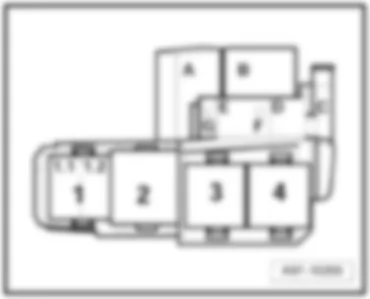
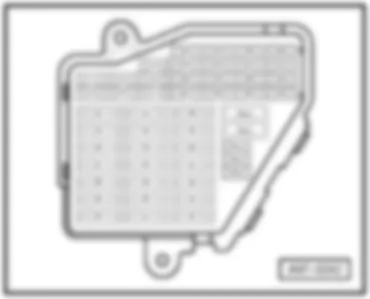
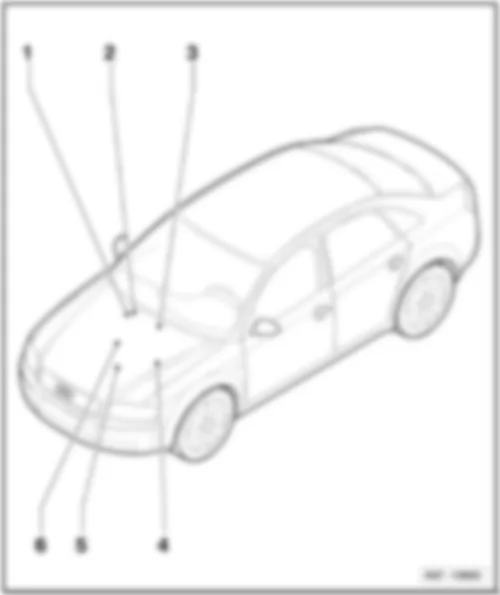
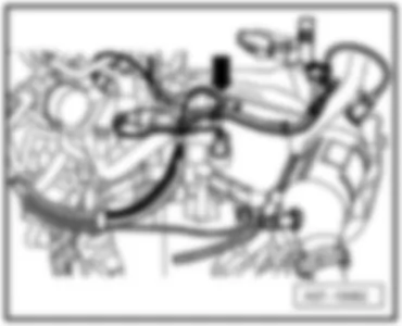
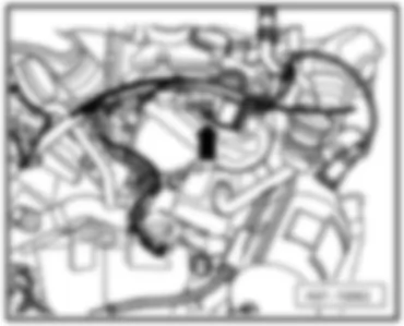
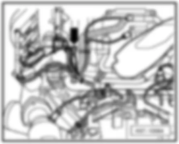
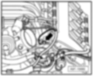
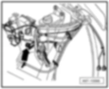
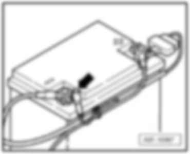
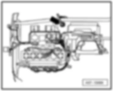
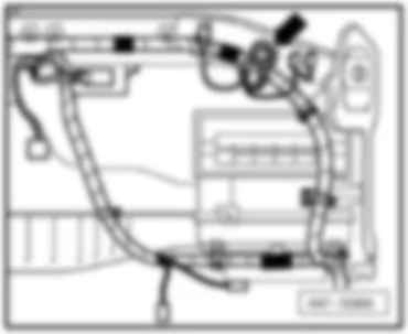
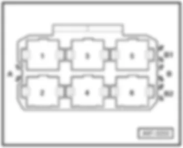
Wiring Diagram AUDI A4 2007 - Battery - starter - alternator - voltage regulator - ignition/starter switch - fuses

| A | Battery |
| B | Starter |
| C | Alternator |
| C1 | Voltage regulator |
| D | Ignition/starter switch |
| J234 | Airbag control unit |
| N253 | Battery isolation igniter |
| S5 | Fuse in relay plate fuse holder |
| S14 | Fuse in relay plate fuse holder |
| S88 | Strip fuse |
| S243 | Fuse in fuse holder |
| T1 | Single connector, black, right engine compartment |
| T2 | 2-pin connector, black, right engine compartment |
| T2af | 2-pin connector, black, on battery isolation igniter |
| 500 | Screw connection 1 (30), on relay plate |
| 501 | Screw connection 2 (30), on relay plate |
| 701 | Earth point in luggage compartment |
| A2 | Positive connection (15), in dash panel wiring harness |
| A32 | Positive connection (30), in dash panel wiring harness |
| A57 | Positive connection 3 (30), in dash panel wiring harness |
| * | Wiring junction B+, in centre plenum chamber |
Wiring Diagram AUDI A4 2007 - Engine control unit - engine component current supply relay - Motronic current supply relay - fuel pump control unit
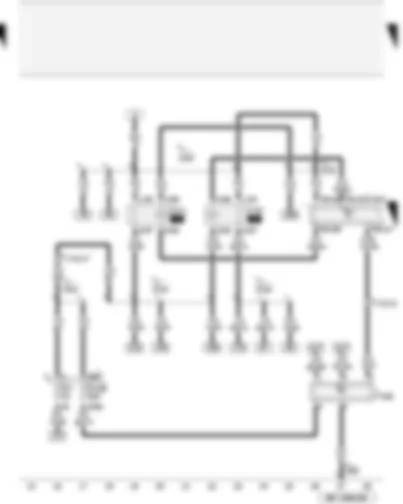
| J271 | Motronic current supply relay |
| J538 | Fuel pump control unit |
| J623 | Engine control unit |
| J757 | Engine component current supply relay |
| S4 | Fuse in relay plate fuse holder |
| S228 | Fuse in fuse holder |
| T17d | 17-pin connector, red, coupling station on electronics box, plenum chamber |
| T17j | 17-pin connector, brown, coupling station on electronics box, plenum chamber |
| T94 | 94-pin connector, black |
| 249 | Earth connection 2, in interior wiring harness |
| A151 | Connection 4 (87), in dash panel wiring harness |
| D50 | Positive connection (30), in engine compartment wiring harness |
| D75 | Positive connection 2 (30), in engine compartment wiring harness |
| D101 | Connection 1, in engine compartment wiring harness |
| D103 | Connection 3, in engine compartment wiring harness |
Wiring Diagram AUDI A4 2007 - Starter motor relay - starter motor relay 2
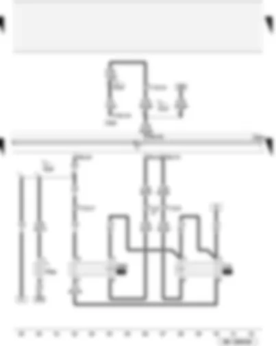
| J53 | Starter motor relay |
| J393 | Convenience system central control unit |
| J623 | Engine control unit |
| J695 | Starter motor relay 2 |
| N36 | Automatic choke series resistor |
| T12h | 12-pin connector, black, on convenience system central control unit (used to be connector 1) |
| T17j | 17-pin connector, brown, coupling station on electronics box, plenum chamber |
| T94 | 94-pin connector, black |
| B207 | Connection (convenience), in interior wiring harness |
| D109 | Connection 7, in engine compartment wiring harness |
| D110 | Connection 8, in engine compartment wiring harness |
| * | For USA only |
Wiring Diagram AUDI A4 2007 - Secondary air pump fuse - vacuum pump for brakes - sport program button
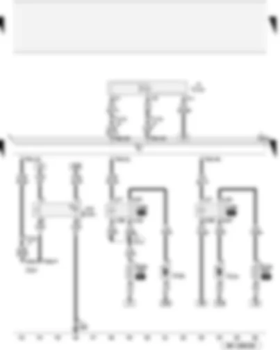
| E541 | Sport program button |
| J299 | Secondary air pump relay |
| J527 | Steering column electronics control unit |
| J569 | Brake servo relay |
| J623 | Engine control unit |
| S130 | Secondary air pump fuse |
| S283 | Brake vacuum pump fuse |
| T16a | 16-pin connector, black, on steering column electronics control unit |
| T17d | 17-pin connector, red, coupling station on electronics box, plenum chamber |
| T17e | 17-pin connector, white, coupling station on electronics box, plenum chamber |
| T60 | 60-pin connector, black |
| T94 | 94-pin connector, black |
| V101 | Secondary air pump motor |
| V144 | Fuel system diagnostic pump |
| V192 | Vacuum pump for brakes |
| 238 | Earth connection 1, in interior wiring harness |
| D111 | Connection 9, in engine compartment wiring harness |
| * | for models with fuel system diagnostic pump only |
| ** | for models with multifunction display only and sport program button, in centre console, for models with sport program button, in steering wheel, ⇒ applicable Current Flow Diagram: sport steering wheel RS |
Wiring Diagram AUDI A4 2007 - Starter button - clutch pedal switch for engine start - right electrohydraulic engine mounting solenoid valve - exhaust flap 1 valve
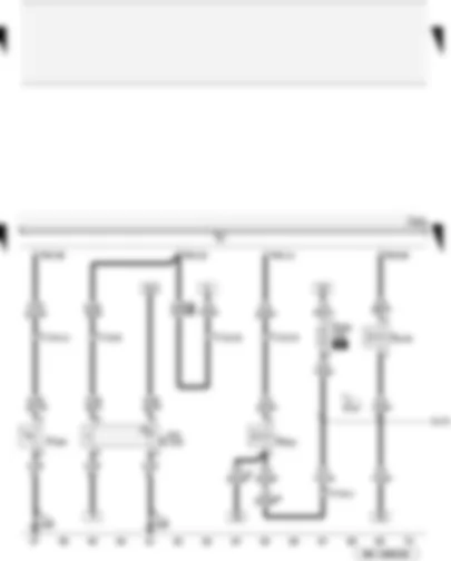
| E378 | Starter button |
| F194 | Clutch pedal switch for engine start |
| J623 | Engine control unit |
| N145 | Right electrohydraulic engine mounting solenoid valve |
| N321 | Exhaust flap 1 valve |
| S282 | Engine electronics fuse |
| T17d | 17-pin connector, red, coupling station on electronics box, plenum chamber |
| T17j | 17-pin connector, brown, coupling station on electronics box, plenum chamber |
| T94 | 94-pin connector, black |
| 238 | Earth connection 1, in interior wiring harness |
| D172 | Connection (engine electrics), in engine compartment wiring harness |
| * | for models with fuel system diagnostic pump only |
| ** | for models with starter button only |
| *** | For USA only |
Wiring Diagram AUDI A4 2007 - Active charcoal filter system solenoid valve 1 - secondary air inlet valve - fuel metering valve - intake manifold flap valve
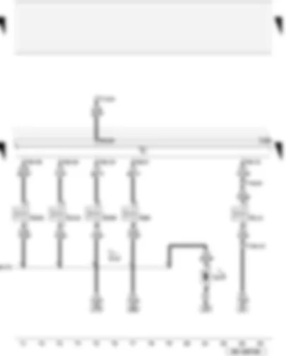
| J623 | Engine control unit |
| N80 | Activated charcoal filter system solenoid valve 1 |
| N112 | Secondary air inlet valve |
| N290 | Fuel metering valve |
| N316 | Intake manifold flap valve |
| N335 | Variable intake manifold change-over valve |
| T14a | 14-pin connector, black, on left in engine compartment |
| T17j | 17-pin connector, brown, coupling station on electronics box, plenum chamber |
| T60 | 60-pin connector, black |
| T94 | 94-pin connector, black |
| V274 | Fan for control unit |
| D172 | Connection (engine electrics), in engine compartment wiring harness |
| * | In electronics box in plenum chamber |
Wiring Diagram AUDI A4 2007 - Brake light switch - accelerator position sender - throttle valve module
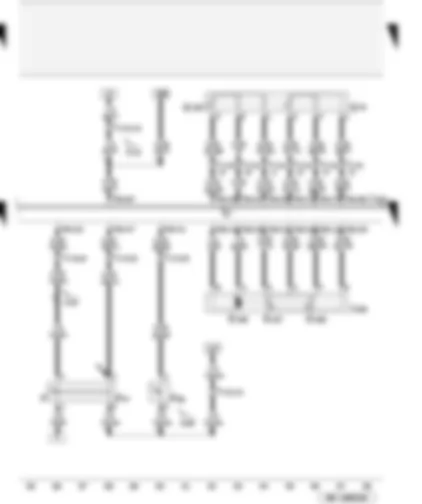
| F | Brake light switch |
| F36 | Clutch pedal switch |
| F47 | Brake pedal switch |
| G79 | Accelerator position sender |
| G185 | Accelerator position sender 2 |
| G186 | Throttle valve drive (electric power control) |
| G187 | Throttle valve drive angle sender 1 for electric throttle |
| G188 | Throttle valve drive angle sender 2 for electric throttle |
| J338 | Throttle valve module |
| J623 | Engine control unit |
| T17d | 17-pin connector, red, coupling station on electronics box, plenum chamber |
| T17e | 17-pin connector, white, coupling station on electronics box, plenum chamber |
| T17j | 17-pin connector, brown, coupling station on electronics box, plenum chamber |
| T60 | 60-pin connector, black |
| T94 | 94-pin connector, black |
| A18 | Connection (54), in dash panel wiring harness |
| A99 | Connection 1 (87), in dash panel wiring harness |
| D51 | Positive connection 1 (15), in engine compartment wiring harness |
| * | ⇒ applicable Current Flow Diagram: anti-lock brake system |
Wiring Diagram AUDI A4 2007 - Knock sensor 1 and 2 - Hall sender 3
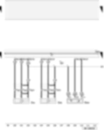
| G61 | Knock sensor 1 |
| G66 | Knock sensor 2 |
| G300 | Hall sender 3 |
| J623 | Engine control unit |
| T3g | 3-pin connector, black, on engine block |
| T3k | 3-pin connector, brown, on engine block |
| T60 | 60-pin connector, black |
| 220 | Earth connection (sender earth), in engine wiring harness |
Wiring Diagram AUDI A4 2007 - Hall sender - coolant temperature sender - fuel pressure sender - intake manifold flap potentiometer
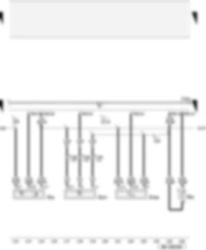
| G40 | Hall sender |
| G62 | Coolant temperature sender |
| G247 | Fuel pressure sender |
| G336 | Intake manifold flap potentiometer |
| J623 | Engine control unit |
| T14a | 14-pin connector, black, on left in engine compartment |
| T60 | 60-pin connector, black |
| 220 | Earth connection (sender earth), in engine wiring harness |
| 316 | Earth connection (sender earth 2), in engine wiring harness |
| D174 | Connection 2 (5V), in engine wiring harness |
Wiring Diagram AUDI A4 2007 - Engine speed sender - brake servo pressure sensor - fuel pressure sender for low pressure
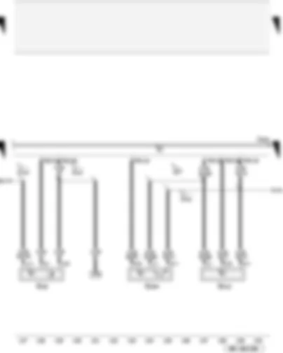
| G28 | Engine speed sender |
| G294 | Brake servo pressure sensor |
| G410 | Fuel pressure sender for low pressure |
| J623 | Engine control unit |
| T60 | 60-pin connector, black |
| T94 | 94-pin connector, black |
| 327 | Earth connection (sender earth), in engine compartment wiring harness |
| D112 | Connection 10, in engine compartment wiring harness |
| D141 | Connection (5V), in engine wiring harness |
| D174 | Connection 2 (5V), in engine wiring harness |
Wiring Diagram AUDI A4 2007 - Air mass meter - inlet camshaft control - engine cooling
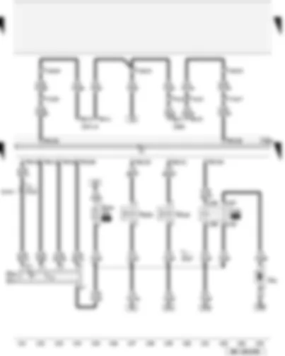
| G42 | Intake air temperature sender |
| G70 | Air mass meter |
| J151 | Continued coolant circulation relay |
| J293 | Radiator fan control unit |
| J623 | Engine control unit |
| J671 | Radiator fan control unit 2 |
| N205 | Inlet camshaft control valve 1 |
| N318 | Exhaust camshaft control valve 1 |
| S344 | Engine electronics fuse 2 |
| T4y | 4-pin connector, black, in engine compartment |
| T6n | 6-pin connector |
| T6o | 6-pin connector |
| T10d | 10-pin connector, grey, coupling station on left of A-pillar |
| T17d | 17-pin connector, red, coupling station on electronics box, plenum chamber |
| T17j | 17-pin connector, brown, coupling station on electronics box, plenum chamber |
| T60 | 60-pin connector, black |
| T94 | 94-pin connector, black |
| V51 | Continued coolant circulation pump |
| D107 | Connection 5, in engine compartment wiring harness |
| D141 | Connection (5V), in engine wiring harness |
| * | for models with radiator fan control unit 2 only |
Wiring Diagram AUDI A4 2007 - Injectors 1 up to 4
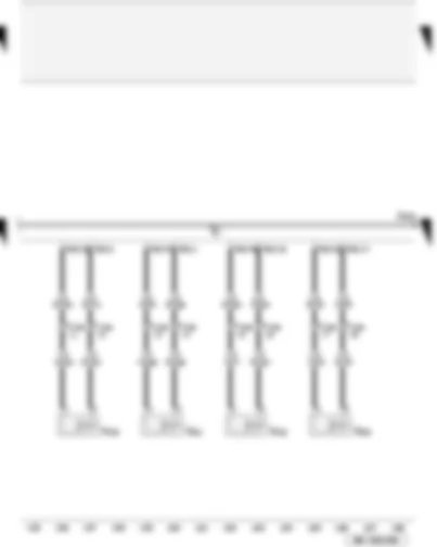
| J623 | Engine control unit |
| N30 | Injector, cylinder 1 |
| N31 | Injector, cylinder 2 |
| N32 | Injector, cylinder 3 |
| N33 | Injector, cylinder 4 |
| T14a | 14-pin connector, black, on left in engine compartment |
| T60 | 60-pin connector, black |
Wiring Diagram AUDI A4 2007 - Engine control unit - Lambda probes
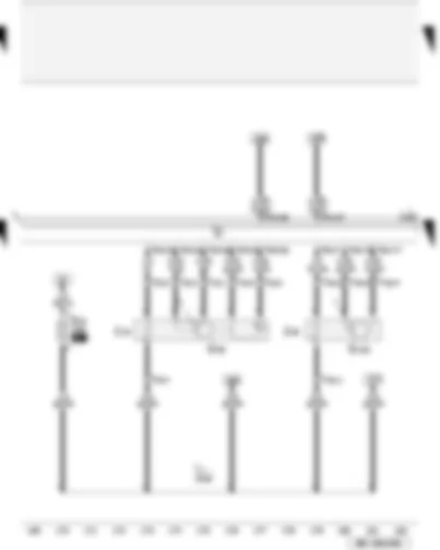
| G39 | Lambda probe |
| G130 | Lambda probe after catalytic converter |
| J623 | Engine control unit |
| S73 | Lambda probe heating thermal fuse |
| T4b | 4-pin connector, black, connector point lambda probe (bulkhead) |
| T6 | 6-pin connector, black, connector point lambda probe (bulkhead) |
| T94 | 94-pin connector, black |
| Z19 | Lambda probe heater |
| Z29 | Lambda probe 1 heater after catalytic converter |
| D108 | Connection 6, in engine compartment wiring harness |
| ● | Data bus wire (CAN bus) |
Wiring Diagram AUDI A4 2007 - Ignition coils 1 up to 4
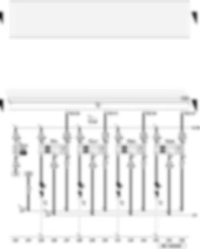
| J623 | Engine control unit |
| N70 | Ignition coil 1 with output stage |
| N127 | Ignition coil 2 with output stage |
| N291 | Ignition coil 3 with output stage |
| N292 | Ignition coil 4 with output stage |
| P | Spark plug connector |
| Q | Spark plugs |
| S131 | Fuse 1 |
| T60 | 60-pin connector, black |
| 131 | Earth connection 2, in engine compartment wiring harness |
| 167 | Earth connection 4, in engine compartment wiring harness |
| D106 | Connection 4, in engine compartment wiring harness |
Wiring Diagram AUDI A4 2007 - Engine control unit fuse - earth connection
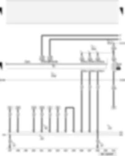
| J623 | Engine control unit |
| S102 | Engine control unit fuse |
| T94 | 94-pin connector, black |
| 18 | Earth point on engine block |
| 19 | Earth point, near coil |
| 83 | Earth connection 1, in front right wiring harness |
| 121 | Earth connection 2, in front right wiring harness |
| 131 | Earth connection 2, in engine compartment wiring harness |
| D102 | Connection 2, in engine compartment wiring harness |
| D106 | Connection 4, in engine compartment wiring harness |
| D113 | Connection 11, in engine compartment wiring harness |
| ● | Data bus wire (CAN bus) |
Wiring Diagram AUDI A4 2007 - Engine control unit 2 - earth connections
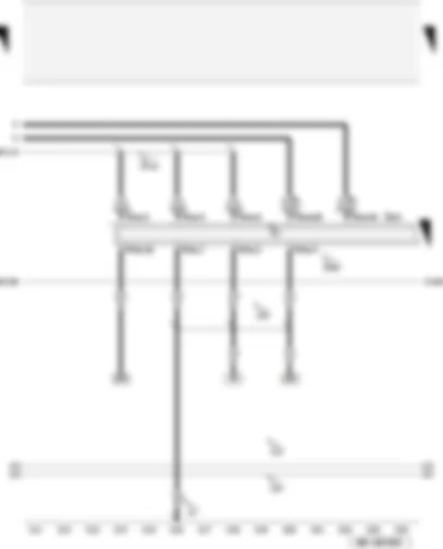
| J624 | Engine control unit 2 |
| T94a | 94-pin connector, black |
| 12 | Earth point, on left in engine compartment |
| 121 | Earth connection 2, in front right wiring harness |
| 131 | Earth connection 2, in engine compartment wiring harness |
| 132 | Earth connection 3, in engine compartment wiring harness |
| D106 | Connection 4, in engine compartment wiring harness |
| D113 | Connection 11, in engine compartment wiring harness |
| ● | Data bus wire (CAN bus) |
Wiring Diagram AUDI A4 2007 - Ignition coils 5 up to 8
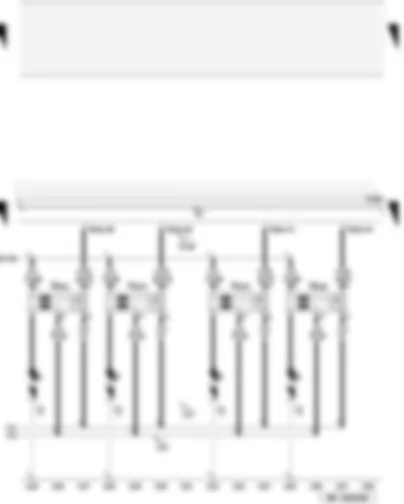
| J624 | Engine control unit 2 |
| N323 | Ignition coil 5 with output stage |
| N324 | Ignition coil 6 with output stage |
| N325 | Ignition coil 7 with output stage |
| N326 | Ignition coil 8 with output stage |
| P | Spark plug connector |
| Q | Spark plugs |
| T60a | 60-pin connector, black |
| 121 | Earth connection 2, in front right wiring harness |
| 131 | Earth connection 2, in engine compartment wiring harness |
| D106 | Connection 4, in engine compartment wiring harness |
Wiring Diagram AUDI A4 2007 - Knock sensors 3 and 4 - inlet camshaft control valve 2
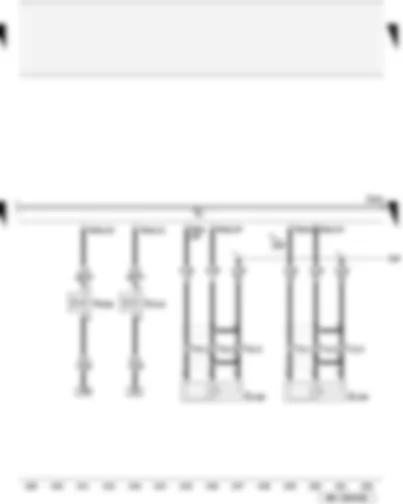
| J624 | Engine control unit 2 |
| G198 | Knock sensor 3 |
| G199 | Knock sensor 4 |
| N208 | Inlet camshaft control valve 2 |
| N319 | Exhaust camshaft control valve 2 |
| T3h | 3-pin connector, black, on engine block |
| T3l | 3-pin connector, brown, on engine block |
| T60a | 60-pin connector, black |
| 328 | Earth connection 2 (sender earth), in engine compartment wiring harness |
Wiring Diagram AUDI A4 2007 - Hall senders 2 and 4 - intake manifold flap potentiometer 2
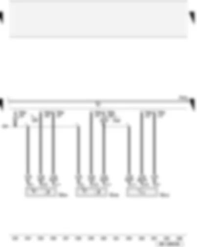
| J624 | Engine control unit 2 |
| G163 | Hall sender 2 |
| G301 | Hall sender 4 |
| G512 | Intake manifold flap 2 potentiometer |
| T60a | 60-pin connector, black |
| 328 | Earth connection 2 (sender earth), in engine compartment wiring harness |
| D190 | Connection 3 (5V), in engine wiring harness |
Wiring Diagram AUDI A4 2007 - Lambda probes 2 - left electrohydraulic engine mounting solenoid valve - fuel metering valve 2
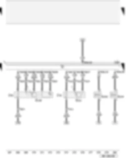
| G108 | Lambda probe 2 |
| G131 | Lambda probe 2 after catalytic converter |
| J624 | Engine control unit 2 |
| N144 | Left electrohydraulic engine mounting solenoid valve |
| N402 | Fuel metering valve 2 |
| T4c | 4-pin connector, brown, connector point lambda probe (bulkhead) |
| T6t | 6-pin connector, brown, connector point lambda probe (bulkhead) |
| T60a | 60-pin connector, black |
| T94a | 94-pin connector, black |
| Z28 | Lambda probe 2 heater |
| Z30 | Lambda probe 2 heater after catalytic converter |
Wiring Diagram AUDI A4 2007 - Injectors 5 up to 8
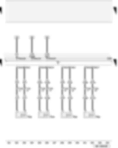
| J624 | Engine control unit 2 |
| N83 | Injector, cylinder 5 |
| N84 | Injector, cylinder 6 |
| N85 | Injector, cylinder 7 |
| N86 | Injector, cylinder 8 |
| T14b | 14-pin connector, black, in engine compartment |
| T60a | 60-pin connector, black |
| T94a | 94-pin connector, black |
Wiring Diagram AUDI A4 2007 - Control unit in dash panel insert
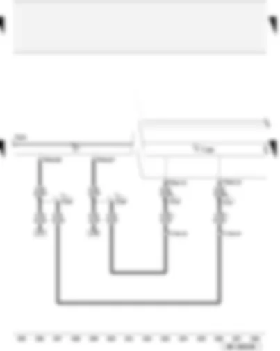
| J285 | Control unit in dash panel insert |
| J624 | Engine control unit 2 |
| T17e | 17-pin connector, white, coupling station on electronics box, plenum chamber |
| T32a | 32-pin connector, green, on dash panel insert |
| T94a | 94-pin connector, black |
| A121 | Connection (high bus), in dash panel wiring harness |
| A122 | Connection (low bus), in dash panel wiring harness |
| D159 | Connection (high bus), in engine compartment wiring harness |
| D160 | Connection (low bus), in engine compartment wiring harness |
| ● | Data bus wire (CAN bus) |
Wiring Diagram AUDI A4 2007 - Oil pressure switch - coolant shortage indicator switch - fuel gauge sender - oil level and oil temperature sender
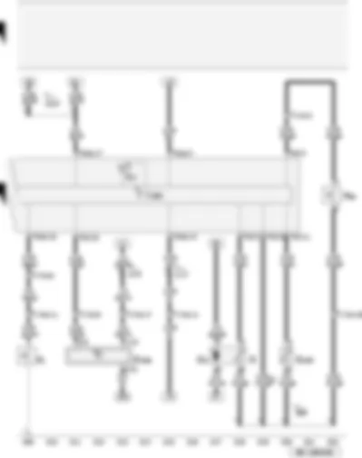
| F1 | Oil pressure switch |
| F66 | Coolant shortage indicator switch |
| G | Fuel gauge sender |
| G6 | Fuel system pressurisation pump |
| G169 | Fuel gauge sender 2 |
| G266 | Oil level and oil temperature sender |
| J285 | Control unit in dash panel insert |
| K2 | Alternator warning lamp |
| T14b | 14-pin connector, black, in engine compartment |
| T17d | 17-pin connector, red, coupling station on electronics box, plenum chamber |
| T17e | 17-pin connector, white, coupling station on electronics box, plenum chamber |
| T32 | 32-pin connector, blue, on dash panel insert |
| T32a | 32-pin connector, green, on dash panel insert |
| 269 | Earth connection (sender earth) 1, in dash panel wiring harness |
| A17 | Connection (61), in dash panel wiring harness |
| A74 | Connection (15a, fuse 5), in dash panel wiring harness |
| A175 | Connection (58s), in dash panel wiring harness |
| * | output for signal earth |
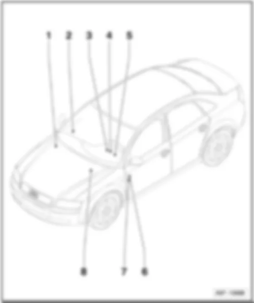
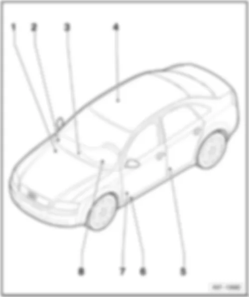
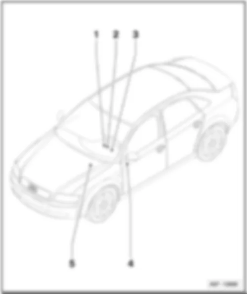
AUDI A4 2007 Control units overview
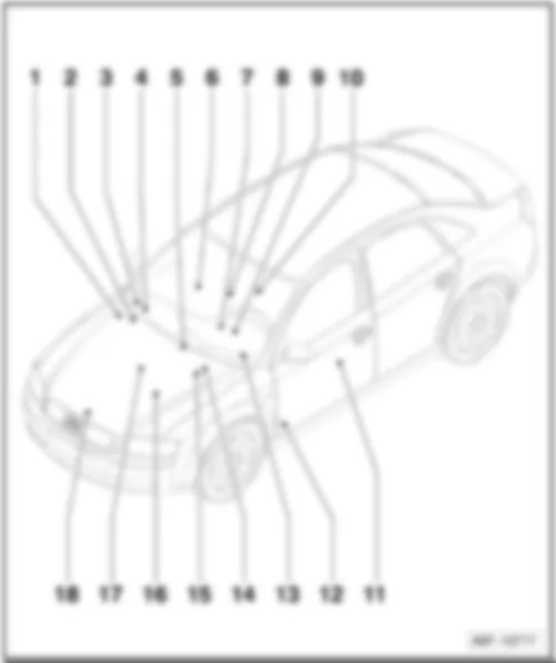
| 1 - | Heated windscreen control unit -J505- |
| q | Location → page 804/4 |
| 2 - | CD changer -R41- |
| q | Location → page 804/13 |
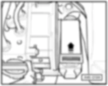
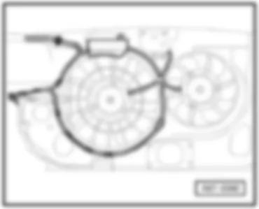
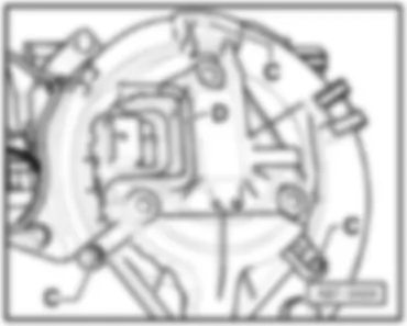
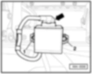
| 3 - | Fresh air blower control unit -J126- |
| q | Location ⇒ page → 804/7 |
| 4 - | Headlight range control, control unit -J431- |
| q | Location → page 804/7 |
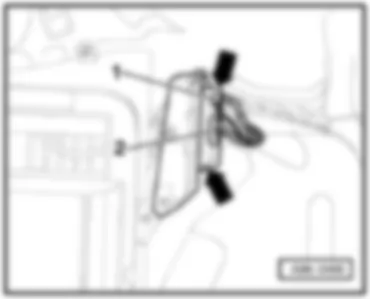
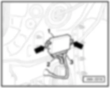
| 5 - | Radio -R- |
| q | not for navigation system |
| q | Location → page 804/11 |
| 5 - | Navigation operating electronics control unit -J402- |
| q | for navigation system RNS-D only |
| q | Location → page 804/11 |
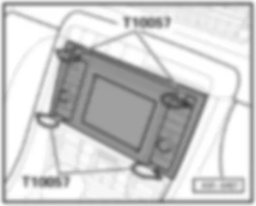
| 5 - | Control unit with display for radio and navigation system -J503- |
| q | for navigation system RNS-Low only |
| q | Location → page 804/13 |
| Audi A4 | Fitting Locations | No. 804 / 2 |
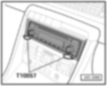
| 5 - | Navigation system with CD drive control unit -J401- |
| q | Location for navigation system NS-Low → page 804/12 |
| q | Location for navigation system RNS-E → page 804/12 |
| 6 - | Telephone and telematics control unit, telematics -J526- |
| q | Location → page 804/14 |
| 6 - | Language input control unit -J507- |
| q | Location → page 804/14 |
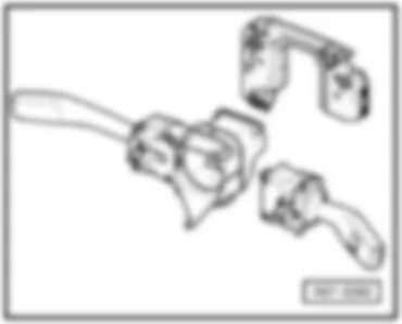
| 7 - | Steering column electronics control unit -J527- |
| q | Location → page 804/8 |
| 8 - | Front passenger side door control unit -J387- |
| q | Location → page 804/16 |
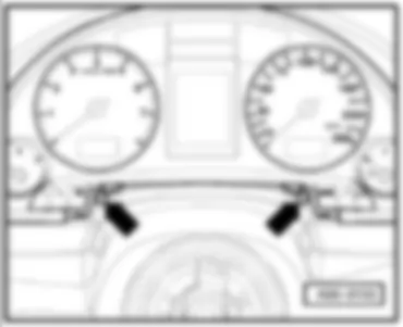
| 9 - | Display control unit in dash panel insert -J285- |
| q | Location → page 804/8 |
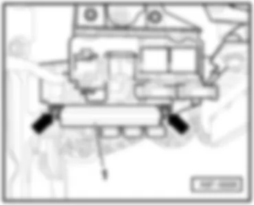
| 10 - | Airbag control unit -J234- |
| q | Location → page 804/9 |
| 11 - | Driver door control unit -J386- |
| q | Location → page 804/16 |
| Audi A4 | Fitting Locations | No. 804 / 3 |
| 12 - | Convenience system central control unit -J393- |
| q | Location → page 804/15 |
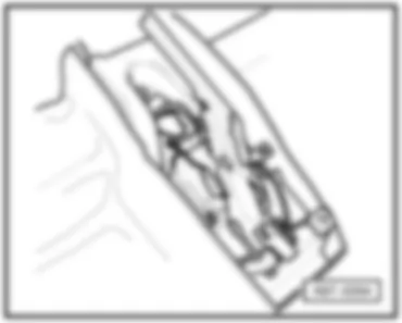
| 13 - | Onboard power supply control unit -J519- |
| q | Location → page 804/9 |
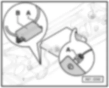
| 14 - | Motronic control unit -J220- |
| 14 - | Diesel direct injection system control unit -J248- |
| 14 - | Simos control unit -J361- |
| q | Location → page 804/4 |
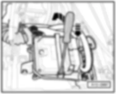
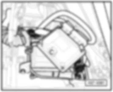
| 15 - | Automatic gearbox control unit -J217- |
| q | not for models with multitronic® |
| q | Location → page 804/5 |
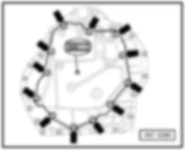
| 16 - | ABS control unit -J104- |
| q | Location → page 804/6 |
| 17 - | Automatic gearbox control unit -J217- |
| q | for models with multitronic® only |
| q | Location → page 804/5 |
| 18 - | Radiator fan control unit -J293- |
| q | Location → page 804/6 |
| Audi A4 | Fitting Locations | No. 804 / 4 |
|
|
| Audi A4 | Fitting Locations | No. 804 / 5 |
|
|
| Audi A4 | Fitting Locations | No. 804 / 6 |
|
|
|
| Audi A4 | Fitting Locations | No. 804 / 7 |
|
|
|
| Audi A4 | Fitting Locations | No. 804 / 8 |
|
|
|
| Audi A4 | Fitting Locations | No. 804 / 9 |
|
|
|
| Audi A4 | Fitting Locations | No. 804 / 10 |
|
|
|
| Audi A4 | Fitting Locations | No. 804 / 11 |
|
|
| Audi A4 | Fitting Locations | No. 804 / 12 |
|
|
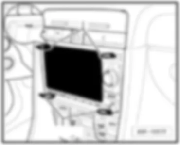
| Audi A4 | Fitting Locations | No. 804 / 13 |
|
|
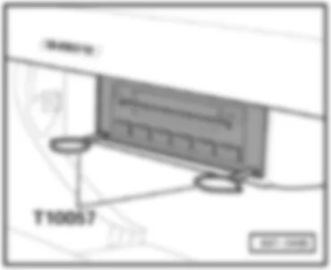
| Audi A4 | Fitting Locations | No. 804 / 14 |
|
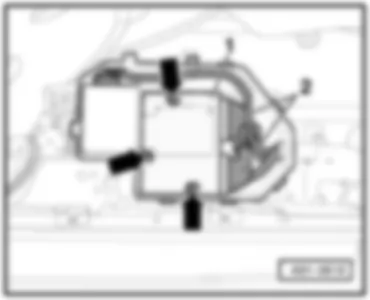
|
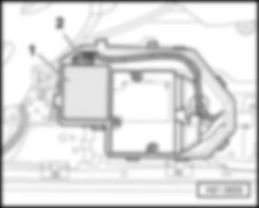
| Audi A4 | Fitting Locations | No. 804 / 15 |
|
|
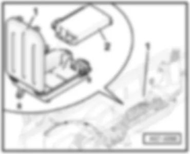
| Audi A4 | Fitting Locations | No. 804 / 16 |
|
|
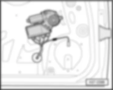
|