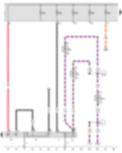
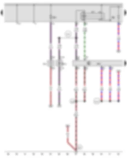
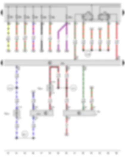
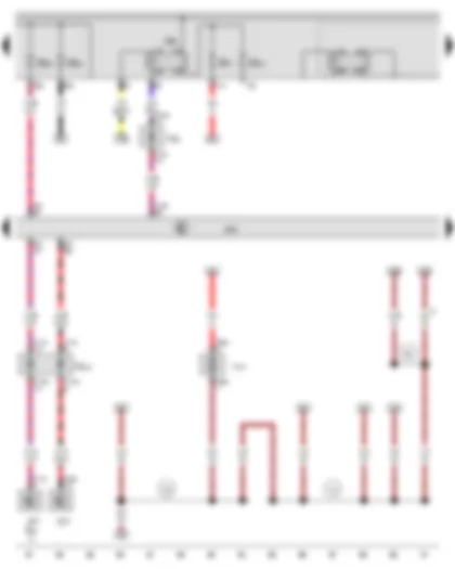
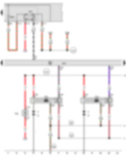
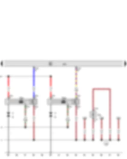
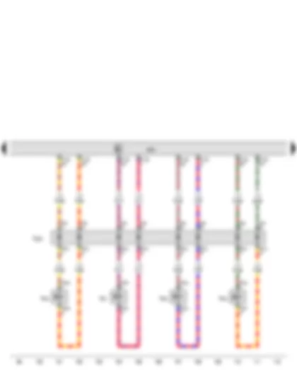
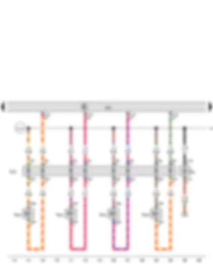
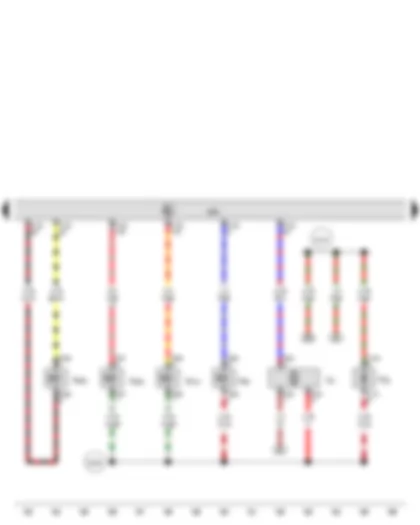
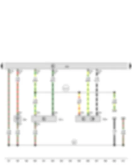
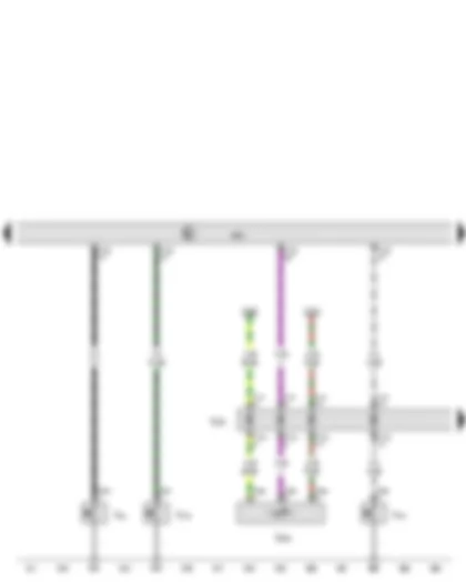
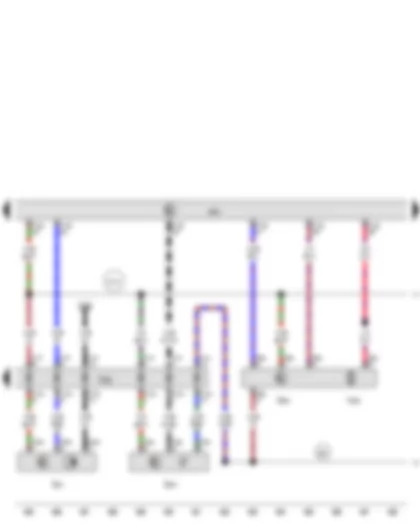
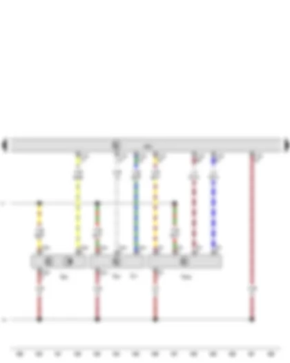
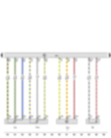
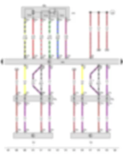
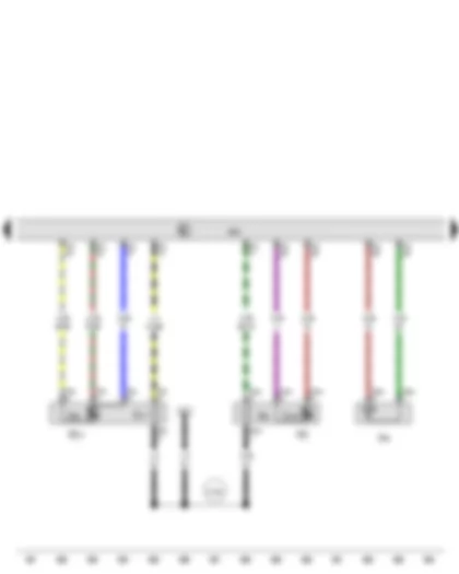
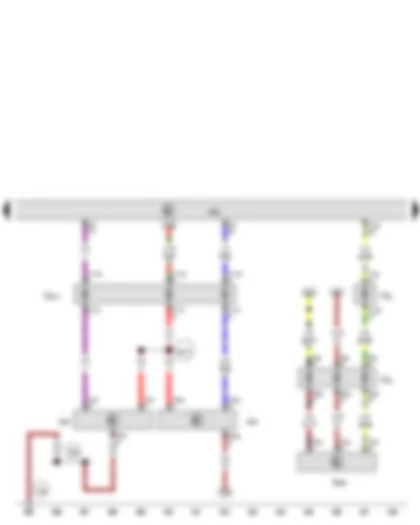
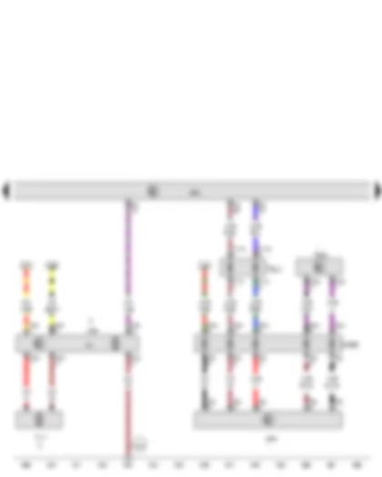
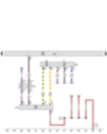
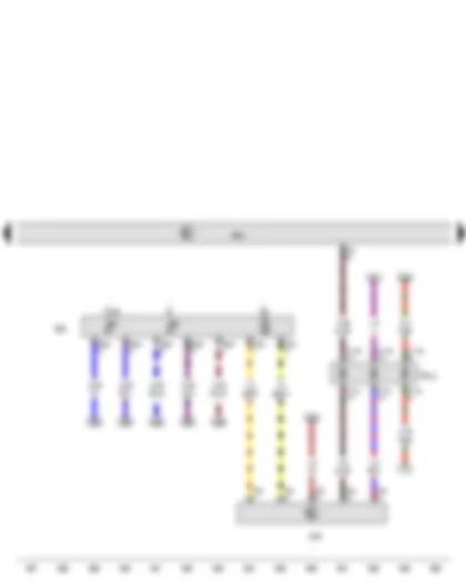
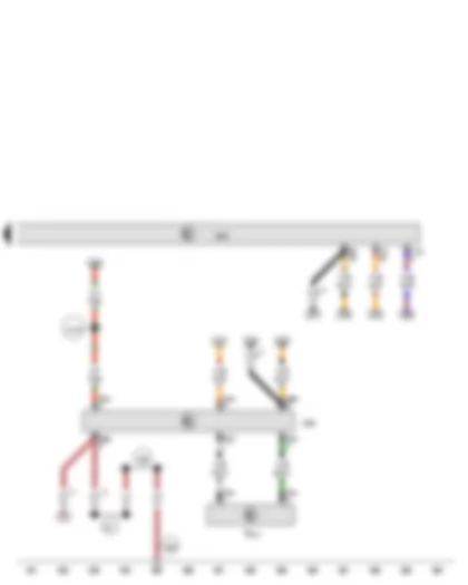
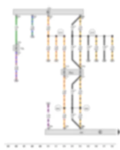
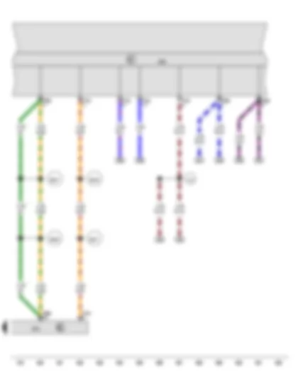
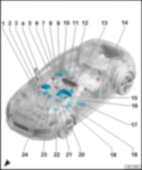
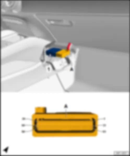
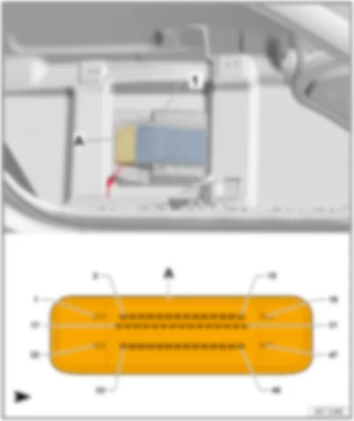
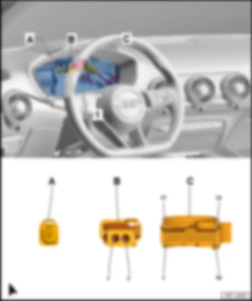
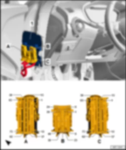
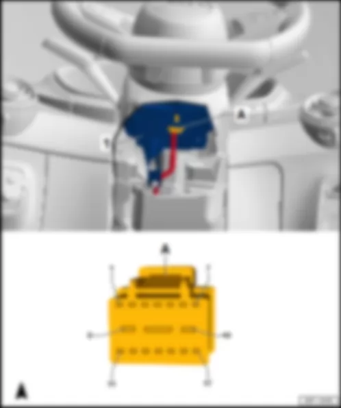
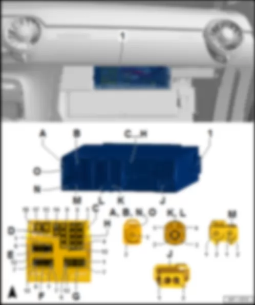
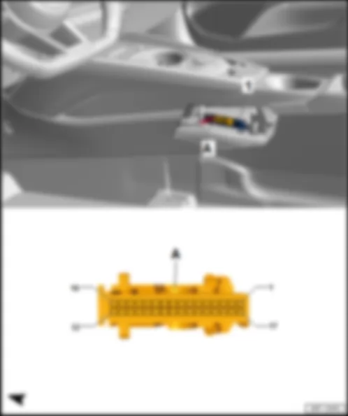
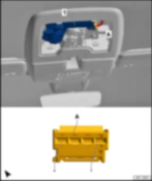
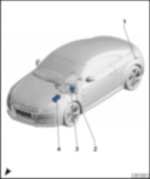
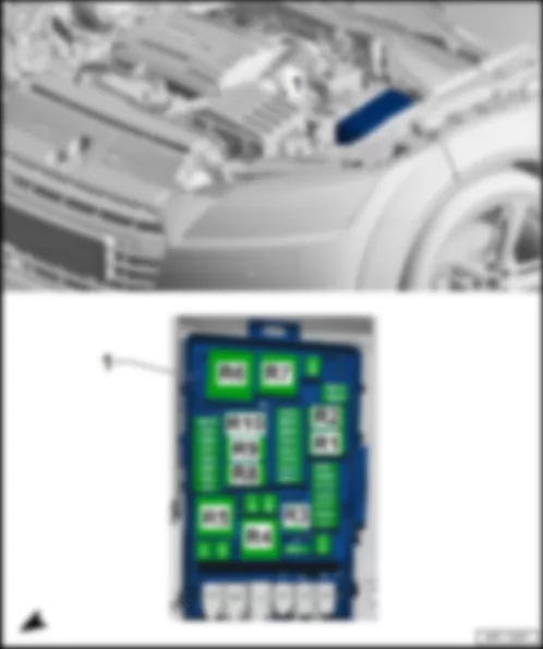
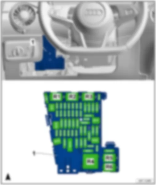
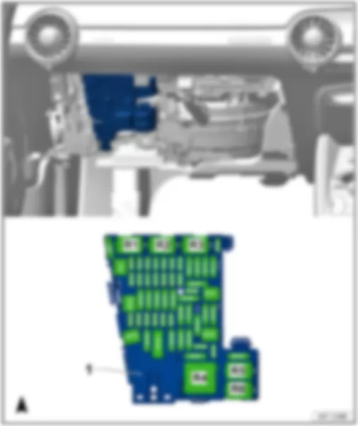
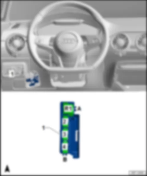
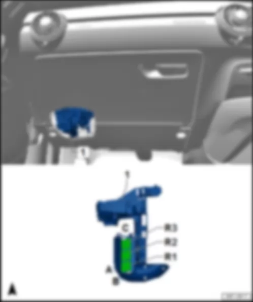
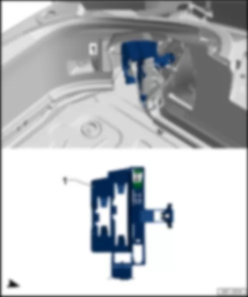
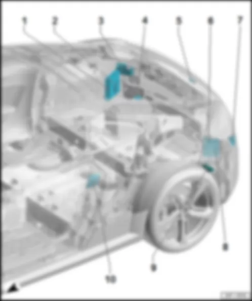
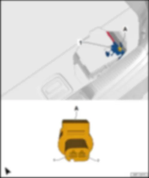
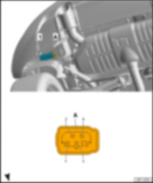
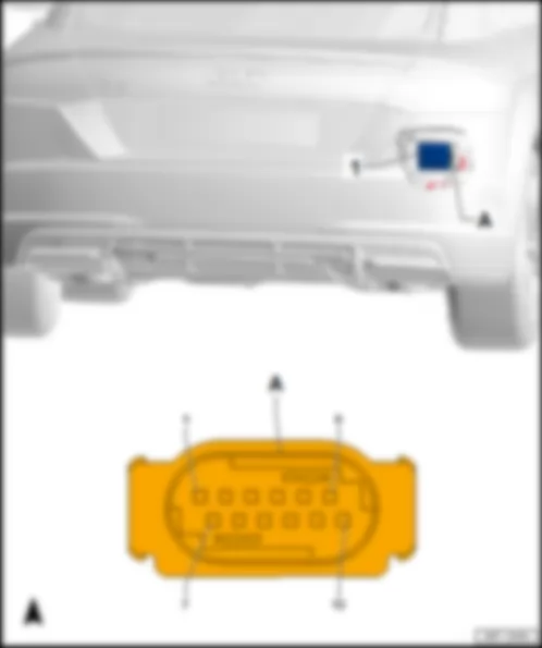
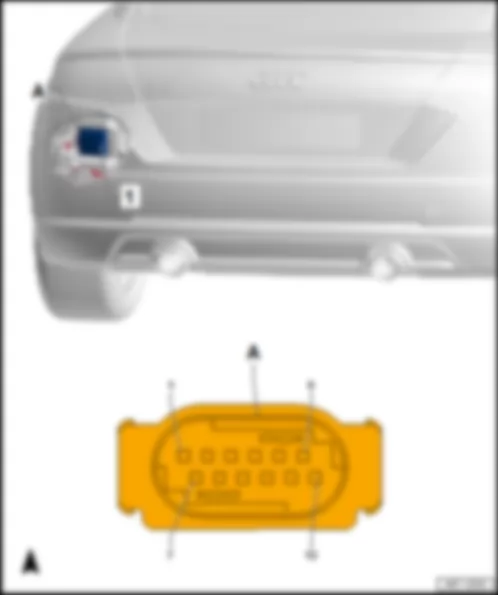
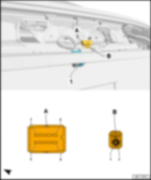
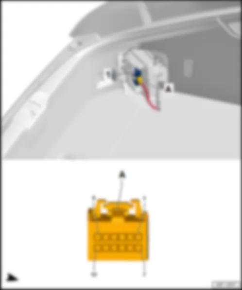
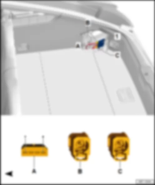
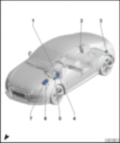
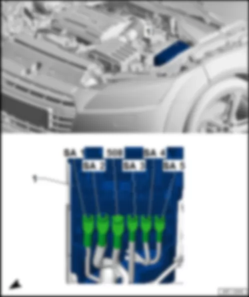
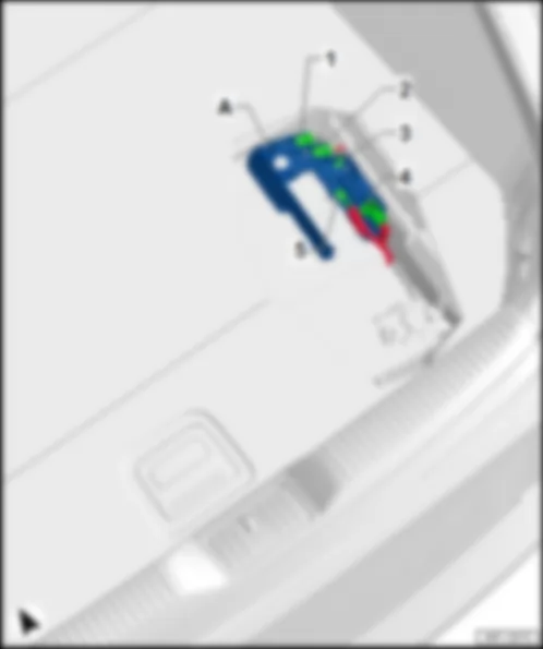
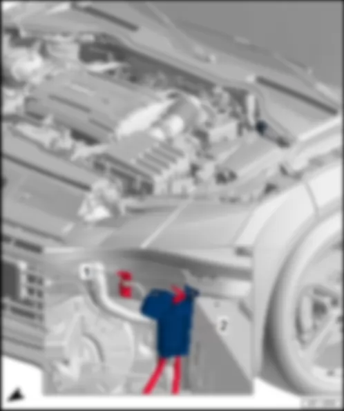
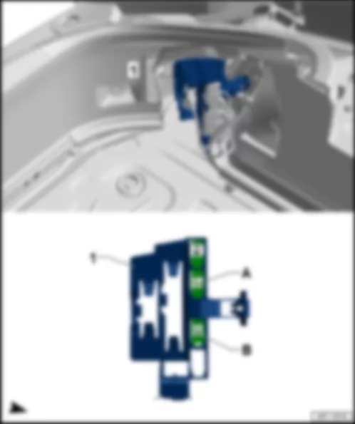
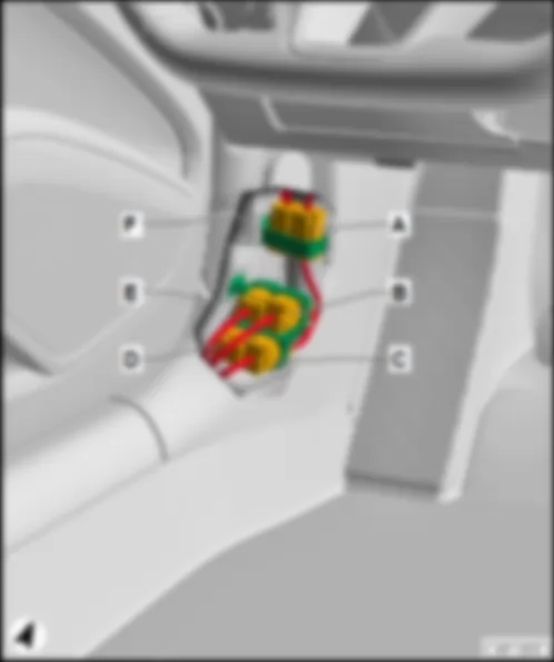
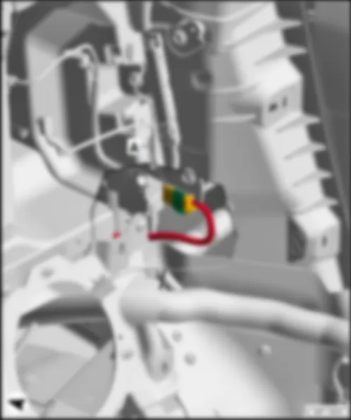
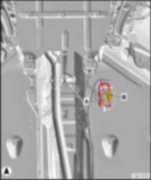
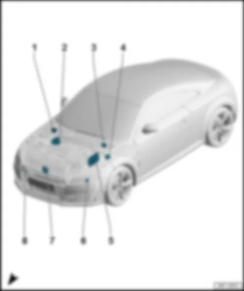
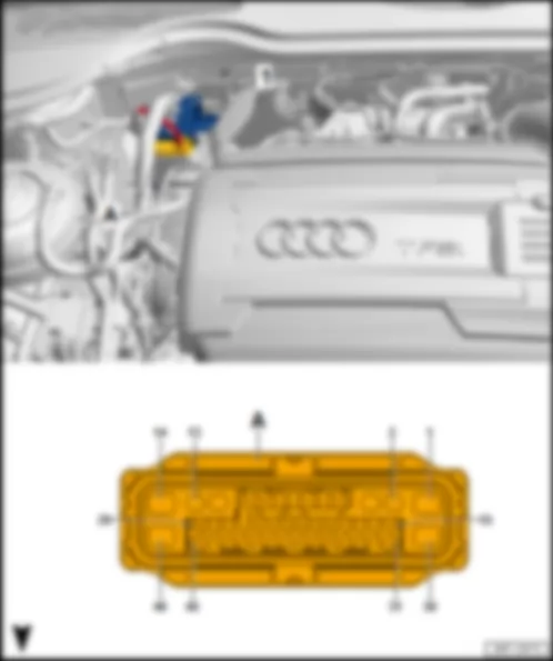
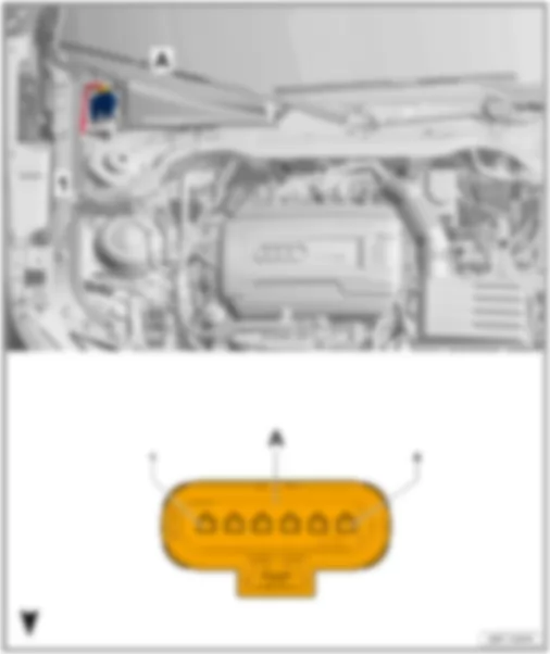
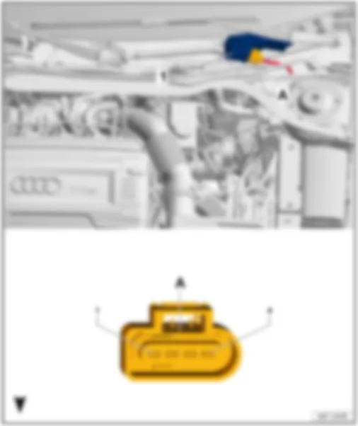
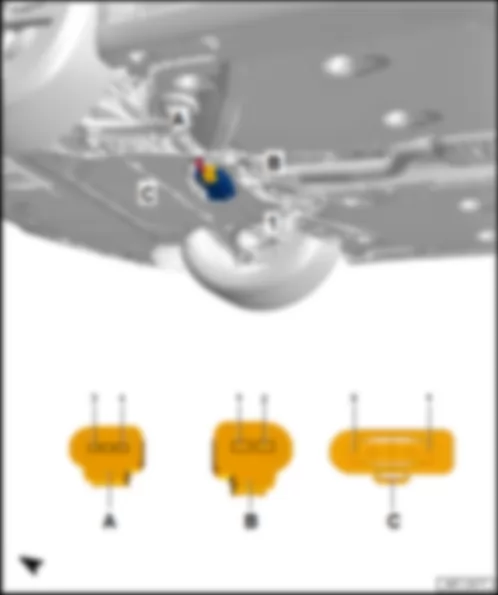
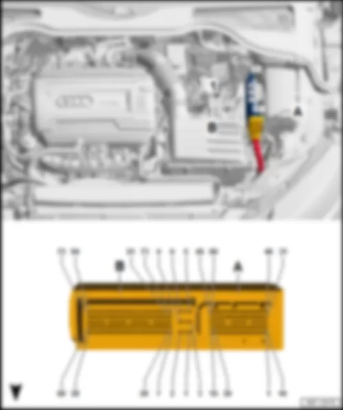
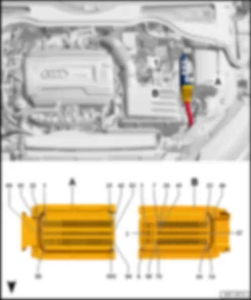
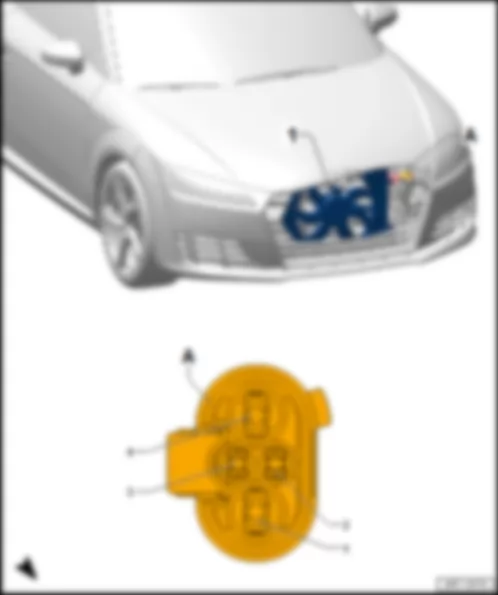
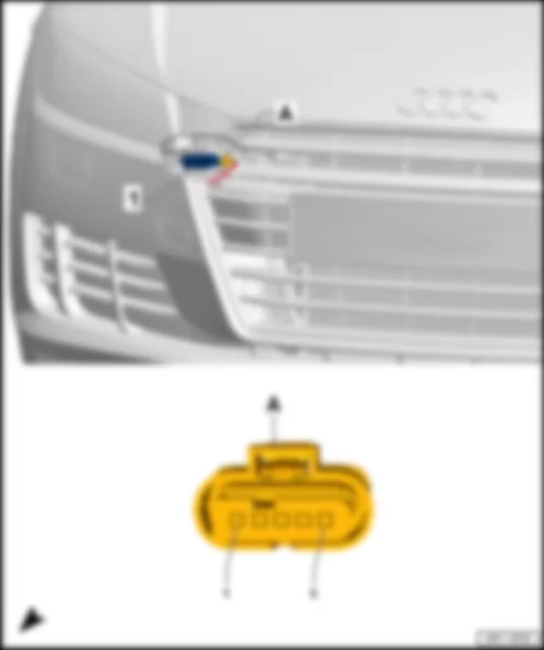
AUDI TT 2016 Fitting location, Climatronic control unit J255 | 1 - | Climatronic control unit -J255- | | B - | 16-pin connector -T16e- , brown | | D - | 12-pin connector -T12d- , black |
| Connector assignment, Climatronic control unit -J255- | | | | | -T16d- (A) | Designation | | -T16e- (B) | Designation | | 1 | Left temperature flap control motor -V158- | | 1 | 5V output, to L2 connection in air conditioning system wiring harness
potentiometer for front air distribution flap control motor -G642-
potentiometer for fresh air/air recirculation, air flow flap control motor -G644-
potentiometer for left temperature flap control motor -G220-
potentiometer for right temperature flap control motor -G221-
potentiometer for defroster flap control motor -G135- | | 2 | Left temperature flap control motor -V158- | | 2 | Potentiometer for left temperature flap control motor -G220- | | 3 | Defroster flap control motor -V107- | | 3 | Potentiometer for right temperature flap control motor -G221- | | 4 | Defroster flap control motor -V107- | | 4 | Potentiometer for defroster flap control motor -G135- | | 5 | Front air distribution flap control motor -V426- | | 5 | Potentiometer for front air distribution flap control motor -G642- | | 6 | Front air distribution flap control motor -V426- | | 6 | | | 7 | | | 7 | Potentiometer for fresh air/air recirculation, air flow flap control motor -G644- | | 8 | | | 8 | Footwell vent temperature sender -G192- | | 9 | Fresh air/air recirculation, air flow flap control motor -V425- | | 9 | | | 10 | Fresh air/air recirculation, air flow flap control motor -V425- | | 10 | | | 11 | Right temperature flap control motor -V159- | | 11 | Evaporator output temperature sender -G263- | | 12 | Right temperature flap control motor -V159- | | 12 | | | 13 | | | 13 | | | 14 | | | 14 | Earth, to 97 earth connection 1 in air conditioning system wiring harness
potentiometer for front air distribution flap control motor -G642-
potentiometer for fresh air/air recirculation, air flow flap control motor -G644-
potentiometer for left temperature flap control motor -G220-
potentiometer for right temperature flap control motor -G221-
potentiometer for defroster flap control motor -G135-
footwell vent temperature sender -G192-
evaporator output temperature sender -G263- | | 15 | | | 15 | | | 16 | | | 16 | |
| -T20c- (C) | Designation | | -T12d- (D) | Designation | | 1 | Sunlight penetration photosensor -G107-
Sunlight penetration photosensor 2 -G134- | | 1 | Dash panel temperature sensor -G56- | | 2 | | | 2 | Dash panel temperature sensor -G56- | | 3 | Sunlight penetration photosensor -G107-
Sunlight penetration photosensor 2 -G134- | | 3 | Dash panel temperature sensor -G56- | | 4 | Terminal 30, to B469 connection 5 in main wiring harness
operating and display unit 2 for air conditioning system -E775-
operating and display unit 3 for air conditioning system -E776-
operating and display unit 4 for air conditioning system -E777-
operating and display unit 1 for air conditioning system -E774-
operating and display unit 5 for air conditioning system -E778- | | 4 | Dash panel temperature sensor -G56- | | 5 | Comfort CAN bus, high to B398 connection 2 (comfort CAN bus, high) in main wiring harness
data bus diagnostic interface -J533- | | 5 | Potentiometer for front right defroster and chest vent shut-off flap control motor -G317- | | 6 | Comfort CAN bus, low to B407 connection 2 (comfort CAN bus, low) in main wiring harness
data bus diagnostic interface -J533- | | 6 | Potentiometer for front right defroster and chest vent shut-off flap control motor -G317- | | 7 | Earth, to 379 earth connection 14 in main wiring harness
operating and display unit 2 for air conditioning system -E775-
operating and display unit 3 for air conditioning system -E776-
operating and display unit 4 for air conditioning system -E777-
operating and display unit 1 for air conditioning system -E774-
operating and display unit 5 for air conditioning system -E778- | | 7 | Defroster button -E782- | | 8 | | | 8 | Defroster warning lamp -K285- | | 9 | 5V output, to B369 connection 1 (5V) in main wiring harness
sunlight penetration photosensor -G107-
sunlight penetration photosensor 2 -G134-
control motor for right side window defroster flap -V410-
control motor for right side window defroster flap -V409- | | 9 | Heated rear window button -E230- | | 10 | Potentiometer for front left defroster and chest vent shut-off flap control motor -G318- | | 10 | Heated rear window warning lamp -K10- | | 11 | Potentiometer for front left defroster and chest vent shut-off flap control motor -G318- | | 11 | Earth, to 378 earth connection 13 in main wiring harness
defroster button -E782-
heated rear window button -E230- | | 12 | Potentiometer for front left defroster and chest vent shut-off flap control motor -G318- | | 12 | Potentiometer for front right defroster and chest vent shut-off flap control motor -G317- | | 13 | Left vent temperature sender -G150- (LHD)
Right vent temperature sender -G151- (RHD) | | | | | 14 | | | | | | 15 | LIN bus, to B710 connection 5 (LIN bus) in main wiring harness
operating and display unit 2 for air conditioning system -E775-
operating and display unit 3 for air conditioning system -E776-
operating and display unit 4 for air conditioning system -E777-
operating and display unit 1 for air conditioning system -E774-
operating and display unit 5 for air conditioning system -E778- | | | | | 16 | LIN bus, to B699 connection 4 (LIN bus) in main wiring harness
fresh air blower control unit -J126-
D108 connection 6 in engine compartment wiring harness
pressure sender for refrigerant circuit -G805-
humidity sender in fresh air intake duct -G657- , air quality sensor -G238- | | | | | 17 | Sensors earth, to 377 earth connection 12 in main wiring harness | | | | | 18 | Air conditioner compressor regulating valve -N280- | | | | | 19 | Terminal 31, to 372 earth connection 7 in main wiring harness
687 earth point 1 on centre tunnel | | | | | 20 | Terminal 30, from fuse holder C -SC-
fuse 3 -S133- | | | |
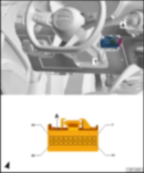
AUDI TT 2016 Fitting location, control unit in dash panel insert J285Fitting location, control unit in dash panel insert -J285- |
| In driver side dash panel. | | The control unit in the dash panel insert -J285- is also a display. | | | | | 1 - | Control unit in dash panel insert -J285- | | B - | 2-pin connector -T2d- , MOST bus, black | | Connector assignment, control unit in dash panel insert -J285- | | | |
| -T32a- (C) | Designation | | -T32a- (C) | Designation | | 1 | Ring break diagnosis, B444 connection 1 (diagnosis) in main wiring harness | | 17 | | | 2 | | | 18 | | | 3 | Comfort CAN bus, low to B406 connection 1 (comfort CAN bus, low) in main wiring harness
B407 connection 2 (comfort CAN bus, low) in main wiring harness
data bus diagnostic interface -J533- | | 19 | | | 4 | Comfort CAN bus, high to B397 connection 1 (comfort CAN bus, high) in main wiring harness
B398 connection 2 (comfort CAN bus, high) in main wiring harness
data bus diagnostic interface -J533- | | 20 | | | 5 | Sender earth, to 410 earth connection 1 (sender earth) in main wiring harness
fuel gauge sender -G-
fuel level sender 2 -G169- | | 21 | | | 6 | Fuel gauge sender -G- | | 22 | | | 7 | Fuel gauge sender -G- | | 23 | | | 8 | Dash panel insert operating buttons -E493- | | 24 | | | 9 | Fuel level sender 2 -G169- | | 25 | | | 10 | Fuel level sender 2 -G169- | | 26 | | | 11 | | | 27 | | | 12 | | | 28 | | | 13 | | | 29 | | | 14 | | | 30 | Terminal 31, to 376 earth connection 11 in main wiring harness
370 earth connection 5 in main wiring harness
687 earth point 1 on centre tunnel | | 15 | Immobiliser reader coil -D2- | | 31 | | | 16 | Immobiliser reader coil -D2- | | 32 | Terminal 30, from fuse holder C -SC- |
AUDI TT 2016 Fitting location, driver door control unit J386 | 1 - | Driver door control unit -J386- | | B - | 20-pin connector -T20f- , black | | D - | 32-pin connector -T32f- , blue |
| Connector assignment, driver door control unit -J386- | | | | | -T6l- (A) | Designation | | -T6l- (A) | Designation | | 1 | | | 4 | | | 2 | | | 5 | | | 3 | Driver side window regulator motor -V147- | | 6 | Driver side window regulator motor -V147- |
| -T20f- (B) | Designation | | -T16f- (C) | Designation | | -T32f- (D) | Designation | | 1 | Driver door lock unit -VX21-
Driver side contact switch in lock cylinder -F241- | | 1 | | | 1 | Central locking SAFELOCK function warning lamp -K133- | | 2 | Microswitch for lowering driver window -E621- | | 2 | Driver side exterior mirror -VX4-
Driver side automatic anti-dazzle exterior mirror -Y20- | | 2 | | | 3 | | | 3 | Terminal 31, to Z1 connection 1 in mirror adjustment - mirror heating wiring harness
driver side exterior mirror -VX4-
heated exterior mirror on driver side -Z4-
driver side turn signal repeater bulb -L131- | | 3 | Driver side door interior handle illumination bulb -L146- | | 4 | | | 4 | Terminal 31, mirror adjustment potentiometer
driver side exterior mirror -VX4- | | 4 | Terminal 58s, to R52 connection (58s) in driver side door wiring harness
alarm system off switch -E217-
operating unit for window regulator in driver door -E512-
mirror adjustment switch -E43-
driver side interior locking button for central locking system -E308-
switch illumination bulb -L156- | | 5 | Driver door lock unit -VX21-
Driver door contact switch -F2- | | 5 | Driver side exterior mirror -VX4-
Driver side mirror adjustment motor -V17-
Driver side mirror adjustment motor -V149- | | 5 | Terminal 31, to 267 earth connection 2 in driver side door wiring harness | | 6 | Driver door lock unit -VX21-
Front left central locking actuator -F131- | | 6 | Driver side exterior mirror -VX4-
Driver side automatic anti-dazzle exterior mirror -Y20- | | 6 | | | 7 | Terminal 31 CL, to driver door lock unit -VX21-
driver door contact switch -F2-
front left central locking actuator -F131-
driver side contact switch in lock cylinder -F241- | | 7 | Driver side exterior mirror -VX4-
Driver side mirror adjustment motor -V17- | | 7 | | | 8 | Mirror signal from B427 connection 1 (mirror signal) in main wiring harness
automatic anti-dazzle interior mirror -Y7- | | 8 | Driver side exterior mirror -VX4-
Driver side mirror adjustment motor -V149- | | 8 | R94 Connection 1 in front passenger side door wiring harness
Driver door storage compartment illumination bulb -L160-
Driver door ambient lighting bulb -L164- | | 9 | | | 9 | Driver side exterior mirror -VX4-
Driver side fold-in mirror motor -V121- | | 9 | | | 10 | | | 10 | Driver side exterior mirror -VX4-
Driver side fold-in mirror motor -V121- | | 10 | Alarm system off switch -E217- | | 11 | Driver door lock unit -VX21-
Driver door central locking SAFELOCK function motor -V161-
Driver door central locking motor -V56- | | 11 | Driver side exterior mirror -VX4-
Driver side turn signal repeater bulb -L131- | | 11 | | | 12 | Driver door lock unit -VX21-
Driver door central locking SAFELOCK function motor -V161- | | 12 | | | 12 | | | 13 | Front passenger door lock unit -VX21-
Driver door central locking motor -V56- | | 13 | Driver side exterior mirror -VX4-
Potentiometer for vertical adjustment of driver side mirror -G515- | | 13 | Terminal 58d, to driver side interior locking button for central locking system -E308- | | 14 | Comfort CAN bus, low to B407 connection 2 (comfort CAN bus, low) in main wiring harness
data bus diagnostic interface -J533- | | 14 | Supply, mirror adjustment potentiometer
Driver side exterior mirror -VX4- | | 14 | | | 15 | Comfort CAN bus, high to B398 connection 2 (comfort CAN bus, high) in main wiring harness
data bus diagnostic interface -J533- | | 15 | Driver side exterior mirror -VX4-
heated exterior mirror on driver side -Z4- | | 15 | | | 16 | | | 16 | Driver side exterior mirror -VX4-
Potentiometer for horizontal adjustment of driver side mirror -G514- | | 16 | Terminal 58, to R65 positive connection (58) in driver-side door wiring harness
Driver side door warning lamp -W30-
Front left entry light -W31- | | 17 | Mirror signal from B428 connection 2 (mirror signal) in main wiring harness
automatic anti-dazzle interior mirror -Y7- | | | | | 17 | | | 18 | | | | | | 18 | | | 19 | Terminal 30, from fuse holder C -SC-
fuse 3 -S133- | | | | | 19 | | | 20 | Terminal 31, to 206 earth connection in front passenger side door wiring harness
373 earth connection 8 in main wiring harness
43 earth point on right A-pillar, bottom | | | | | 20 | Alarm system off switch -E217-
Interior monitoring switch -E183- | | | | | | | | 21 | Terminal 31, to 267 earth connection 2 in driver side door wiring harness | | | | | | | | 22 | | | | | | | | | 23 | | | | | | | | | 24 | Mirror adjustment switch -E43- | | | | | | | | 25 | Mirror adjustment switch -E43-
Adjustment switch for mirror with fold-in feature -E168-
Mirror adjustment changeover switch -E48- | | | | | | | | 26 | | | | | | | | | 27 | | | | | | | | | 28 | Driver side interior locking button for central locking system -E308- | | | | | | | | 29 | | | | | | | | | 30 | | | | | | | | | 31 | Operating unit for window regulator in driver door -E512-
Front right window regulator switch in driver door -E81- | | | | | | | | 32 | Operating unit for window regulator in driver door -E512-
Front right window regulator switch -E40- |
AUDI TT 2016 Fitting location, front passenger door control unit J387 | 1 - | Front passenger door control unit -J387- | | B - | 20-pin connector -T20g- , black | | D - | 32-pin connector -T32g- , blue |
| Connector assignment, front passenger door control unit -J387- | | | | | -T6m- (A) | Designation | | -T6m- (A) | Designation | | 1 | | | 4 | | | 2 | | | 5 | | | 3 | Front passenger side window regulator motor -V148- | | 6 | Front passenger side window regulator motor -V148- |
| -T20g- (B) | Designation | | -T16g- (C) | Designation | | -T32g- (D) | Designation | | 1 | | | 1 | | | 1 | | | 2 | Microswitch for lowering front passenger window -E622- | | 2 | Front passenger side exterior mirror -VX5-
Front passenger side automatic anti-dazzle exterior mirror -Y21- | | 2 | | | 3 | | | 3 | Terminal 31, to Z2 connection 2 in mirror adjustment - mirror heating wiring harness
front passenger side exterior mirror -VX5-
heated exterior mirror on front passenger side -Z5-
front passenger side turn signal repeater bulb -L132- | | 3 | Front passenger side door interior handle illumination bulb -L147- | | 4 | | | 4 | Terminal 31, mirror adjustment potentiometer
front passenger side exterior mirror -VX5- | | 4 | Terminal 58s, to R53 connection (58s) in front passenger side door wiring harness
front passenger side interior locking button for central locking system -E309-
window regulator switch in front passenger door -E107-
switch illumination bulb -L156- | | 5 | Front passenger door lock unit -VX22-
Front passenger door contact switch -F3- | | 5 | Front passenger side exterior mirror -VX5-
Front passenger side mirror adjustment motor -V25-
Front passenger side mirror adjustment motor -V150- | | 5 | Terminal 31, to window regulator switch in front passenger door -E107-
268 earth connection 2 in front passenger side door wiring harness
| | 6 | Front passenger door lock unit -VX22-
Front right central locking actuator -F133- | | 6 | Front passenger side exterior mirror -VX5-
Front passenger side automatic anti-dazzle exterior mirror -Y21- | | 6 | | | 7 | Terminal 31 CL, to front passenger door lock unit -VX22-
front passenger door contact switch -F3-
front right central locking actuator -F133- | | 7 | Front passenger side exterior mirror -VX5-
Front passenger side mirror adjustment motor -V25- | | 7 | | | 8 | Mirror signal from B427 connection 1 (mirror signal) in main wiring harness
automatic anti-dazzle interior mirror -Y7- | | 8 | Front passenger side exterior mirror -VX5-
Front passenger side mirror adjustment motor -V150- | | 8 | R98 connection 1 in front passenger side door wiring harness
front passenger door storage compartment illumination bulb -L161-
front passenger door ambient lighting bulb -L165- | | 9 | | | 9 | Front passenger side exterior mirror -VX5-
Front passenger side fold-in mirror motor -V122- | | 9 | | | 10 | | | 10 | Front passenger side exterior mirror -VX5-
Front passenger side fold-in mirror motor -V122- | | 10 | | | 11 | Front passenger door lock unit -VX22-
Front passenger door central locking SAFELOCK function motor -V162-
Front passenger seat central locking motor -V57- | | 11 | Front passenger side exterior mirror -VX5-
Front passenger side turn signal repeater bulb -L132- | | 11 | | | 12 | Front passenger door lock unit -VX22-
Front passenger door central locking SAFELOCK function motor -V162- | | 12 | | | 12 | | | 13 | Front passenger door lock unit -VX22-
Front passenger seat central locking motor -V57- | | 13 | Front passenger side exterior mirror -VX5-
Potentiometer for vertical adjustment of front passenger side mirror -G517- | | 13 | Terminal 58d, to front passenger side interior locking button for central locking system -E309-
| | 14 | Comfort CAN bus, low to B407 connection 2 (comfort CAN bus, low) in main wiring harness
data bus diagnostic interface -J533- | | 14 | Supply, mirror adjustment potentiometer
Front passenger side exterior mirror -VX5- | | 14 | | | 15 | Comfort CAN bus, high to B398 connection 2 (comfort CAN bus, high) in main wiring harness
data bus diagnostic interface -J533- | | 15 | Front passenger side exterior mirror -VX5-
Heated exterior mirror on front passenger side -Z5- | | 15 | | | 16 | | | 16 | Front passenger side exterior mirror -VX5-
Potentiometer for horizontal adjustment of front passenger side mirror -G516- | | 16 | Terminal 58, to R67 positive connection (58) in front passenger side door wiring harness
front right entry light -W32-
front passenger side door warning lamp -W36- | | 17 | Mirror signal from B428 connection 2 (mirror signal) in main wiring harness
automatic anti-dazzle interior mirror -Y7- | | | | | 17 | | | 18 | | | | | | 18 | | | 19 | Terminal 30, from fuse holder C -SC-
fuse 3 -S133- | | | | | 19 | | | 20 | Terminal 31, to 206 earth connection in front passenger side door wiring harness
373 earth connection 8 in main wiring harness
43 earth point on right A-pillar, bottom | | | | | 20 | | | | | | | | | 21 | | | | | | | | | 22 | | | | | | | | | 23 | | | | | | | | | 24 | | | | | | | | | 25 | | | | | | | | | 26 | | | | | | | | | 27 | | | | | | | | | 28 | | | | | | | | | 29 | | | | | | | | | 30 | | | | | | | | | 31 | | | | | | | | | 32 | Window regulator switch in front passenger door -E107- |
AUDI TT 2016 Fitting location, headlight range control unit J431 |
| 1 - | Headlight range control unit -J431- | | Connector assignment, headlight range control unit -J431- | | | | | -T26b- (A) | Designation | | -T26b- (A) | Designation | | 1 | | | 14 | | | 2 | Extended CAN bus, high to E135 connection (extended CAN bus, high) in engine compartment wiring harness
B108 connection 1 (extended CAN bus, high) in main wiring harness
data bus diagnostic interface -J533- | | 15 | Control unit for left daytime running light and side light -J860-
Left headlight range control motor -V48- | | 3 | Extended CAN bus, low to E136 connection (extended CAN bus, low) in engine compartment wiring harness
B109 connection 1 (extended CAN bus, low) in main wiring harness
data bus diagnostic interface -J533- | | 16 | Control unit for right daytime running light and side light -J861-
Right headlight range control motor -V49- | | 4 | CAN bus, to D178 connection 2 (high bus) in engine compartment wiring harness
front left headlight -MX1- /front right headlight -MX2- , LED, matrix beam | | 17 | Control unit for right daytime running light and side light -J861-
Right headlight range control motor -V49- | | 5 | CAN bus, to D179 connection 2 (low bus) in engine compartment wiring harness
front left headlight -MX1- /front right headlight -MX2- , LED, matrix beam | | 18 | Control unit for right daytime running light and side light -J861-
Right headlight range control motor -V49- | | 6 | | | 19 | Control unit for right daytime running light and side light -J861-
Right headlight range control motor -V49- | | 7 | Rear left vehicle level sender -G76- | | 20 | Control unit for left daytime running light and side light -J860-
Left headlight range control motor -V48- | | 8 | Terminal 56, from D152 positive connection 1 (56b) in engine compartment wiring harness
onboard supply control unit -J519- | | 21 | Control unit for left daytime running light and side light -J860-
Left headlight range control motor -V48- | | 9 | | | 22 | Control unit for left daytime running light and side light -J860-
Left headlight range control motor -V48- | | 10 | Rear left vehicle level sender -G76- | | 23 | Terminal 15, from D200 positive connection 3 (15a) in engine compartment wiring harness
fuse holder C -SC- | | 11 | Rear left vehicle level sender -G76- | | 24 | Terminal 31, to 131 earth connection 2 in engine compartment wiring harness
132 earth connection 3 in engine compartment wiring harness
671 earth point 1 on front side member, left | | 12 | | | 25 | | | 13 | | | 26 | |
| 1 - | Headlight range control unit -J431- | | A - | 26-pin connector -T26b- , black |
| Connector assignment, headlight range control unit -J431- | | | | | -T26b- (A) | Designation | | -T26b- (A) | Designation | | 1 | | | 14 | | | 2 | Extended CAN bus, high to E135 connection (extended CAN bus, high) in engine compartment wiring harness
B108 connection 1 (extended CAN bus, high) in main wiring harness
data bus diagnostic interface -J533- | | 15 | Control unit for left daytime running light and side light -J860-
Left headlight range control motor -V48- | | 3 | Extended CAN bus, low to E136 connection (extended CAN bus, low) in engine compartment wiring harness
B109 connection 1 (extended CAN bus, low) in main wiring harness
data bus diagnostic interface -J533- | | 16 | Control unit for right daytime running light and side light -J861-
Right headlight range control motor -V49- | | 4 | CAN bus, to D178 connection 2 (high bus) in engine compartment wiring harness
front left headlight -MX1- /front right headlight -MX2- , LED, matrix beam | | 17 | Control unit for right daytime running light and side light -J861-
Right headlight range control motor -V49- | | 5 | CAN bus, to D179 connection 2 (low bus) in engine compartment wiring harness
front left headlight -MX1- /front right headlight -MX2- , LED, matrix beam | | 18 | Control unit for right daytime running light and side light -J861-
Right headlight range control motor -V49- | | 6 | | | 19 | Control unit for right daytime running light and side light -J861-
Right headlight range control motor -V49- | | 7 | Rear left vehicle level sender -G76- | | 20 | Control unit for left daytime running light and side light -J860-
Left headlight range control motor -V48- | | 8 | Terminal 56, from D152 positive connection 1 (56b) in engine compartment wiring harness
onboard supply control unit -J519- | | 21 | Control unit for left daytime running light and side light -J860-
Left headlight range control motor -V48- | | 9 | | | 22 | Control unit for left daytime running light and side light -J860-
Left headlight range control motor -V48- | | 10 | Rear left vehicle level sender -G76- | | 23 | Terminal 15, from D200 positive connection 3 (15a) in engine compartment wiring harness
fuse holder C -SC- | | 11 | Rear left vehicle level sender -G76- | | 24 | Terminal 31, to 131 earth connection 2 in engine compartment wiring harness
132 earth connection 3 in engine compartment wiring harness
671 earth point 1 on front side member, left | | 12 | | | 25 | | | 13 | | | 26 | |
AUDI TT 2016 | 1 - | Parking aid control unit -J446- /park assist steering control unit -J791- | | B - | 26-pin connector -T26a- , black |
| Connector assignment of parking aid control unit -J446- /park assist steering control unit -J791- | | | | | -T18a- (A) | Designation | | -T18a- (A) | Designation | | 1 | | | 10 | Earth to 348 earth connection (parking aid) in front bumper wiring harness
front left parking aid sender -G255-
front centre left parking aid sender -G254-
front centre right parking aid sender -G253-
front right parking aid sender -G252-
front left sender for park assist steering on left side of vehicle -G568-
front right sender for park assist steering on right side of vehicle -G569- | | 2 | Front left sender for park assist steering on left side of vehicle -G568- | | 11 | Front left parking aid sender -G255- | | 3 | Front centre left parking aid sender -G254- | | 12 | Front centre right parking aid sender -G253- | | 4 | Front right parking aid sender -G252- | | 13 | Front right sender for park assist steering on right side of vehicle -G569- | | 5 | | | 14 | Voltage supply to X65 connection (parking aid) in front bumper wiring harness
front left parking aid sender -G255-
front centre left parking aid sender -G254-
front centre right parking aid sender -G253-
front right parking aid sender -G252-
front left sender for park assist steering on left side of vehicle -G568-
front right sender for park assist steering on right side of vehicle -G569- | | 6 | | | 15 | | | 7 | | | 16 | | | 8 | | | 17 | | | 9 | | | 18 | |
| -T26a- (B) | Designation | | -T26a- (B) | Designation | | 1 | | | 14 | Terminal 15, from B279 positive connection 3 (15a) in main wiring harness
fuse holder C -SC- | | 2 | Front parking aid warning buzzer -H22- | | 15 | Rear parking aid warning buzzer -H15- | | 3 | Park assist steering button -E581- | | 16 | Parking aid button -E266- | | 4 | Warning light for park assist steering -K241- | | 17 | Parking aid warning lamp -K136- | | 5 | | | 18 | Voltage supply to X68 connection (parking aid) in rear bumper wiring harness
rear left park assist steering sender -G716-
rear right park assist steering sender -G717-
rear left parking aid sender -G203-
rear centre left parking aid sender -G204-
rear centre right parking aid sender -G205-
rear right parking aid sender -G206- | | 6 | Rear left parking aid sender -G203- | | 19 | Rear left park assist steering sender -G716- | | 7 | Rear centre right parking aid sender -G205- | | 20 | Rear centre left parking aid sender -G204- | | 8 | Rear right park assist steering sender -G717- | | 21 | Rear right parking aid sender -G206- | | 9 | Rear parking aid warning buzzer -H15- | | 22 | Earth to 352 earth connection (parking aid) in rear bumper wiring harness
rear left park assist steering sender -G716-
rear right park assist steering sender -G717-
rear left parking aid sender -G203-
rear centre left parking aid sender -G204-
rear centre right parking aid sender -G205-
rear right parking aid sender -G206- | | 10 | Front parking aid warning buzzer -H22- | | 23 | Chassis/dash panel insert CAN bus, low
B677 connection 2 (chassis/dash panel insert CAN bus, low) in main wiring harness
data bus diagnostic interface -J533- | | 11 | | | 24 | Chassis/dash panel insert CAN bus, high
B673 connection 2 (chassis/dash panel insert CAN bus, high) in main wiring harness
data bus diagnostic interface -J533- | | 12 | | | 25 | | | 13 | Terminal 31, to 372 earth connection 7 in main wiring harness
687 earth point 1 on centre tunnel | | 26 | |
AUDI TT 2016 Fitting location, entry and start authorisation control unit J518 |
| 1 - | Entry and start authorisation control unit -J518- | | Connector assignment, entry and start authorisation control unit -J518- | | | | | -T40a- (A) | Designation | | -T40a- (A) | Designation | | 1 | | | 21 | Rear right aerial for entry and start authorisation -R166- | | 2 | | | 22 | Rear left aerial for entry and start authorisation -R165- | | 3 | | | 23 | Luggage compartment aerial for entry and start system -R137- | | 4 | | | 24 | Rear left aerial for entry and start authorisation -R165- | | 5 | Comfort CAN bus, low to B407 connection 2 (comfort CAN bus, low) in main wiring harness
data bus diagnostic interface -J533- | | 25 | | | 6 | Comfort CAN bus, high to B398 connection 2 (comfort CAN bus, high) in main wiring harness
data bus diagnostic interface -J533- | | 26 | Onboard supply control unit -J519- | | 7 | Entry and start authorisation button -E408- | | 27 | Onboard supply control unit -J519- | | 8 | Operating unit in front of centre console -E461-
Entry and start authorisation button -E408- | | 28 | | | 9 | | | 29 | | | 10 | | | 30 | Terminal 30, from fuse holder C -SC-
fuse 2 -S132- | | 11 | from coupling point on front left door -TTVL-
contact sensor for front left exterior door handle -G605- | | 31 | Entry and start authorisation aerial -R249- | | 12 | from coupling point on front right door -TTVR-
driver door exterior handle contact sensor -G415- | | 32 | Rear right aerial for entry and start authorisation -R166- | | 13 | | | 33 | Luggage compartment aerial for entry and start system -R137- | | 14 | | | 34 | Entry and start authorisation aerial -R249- | | 15 | to coupling point on left A-pillar, bottom -TALU-
engine control unit -J623- | | 35 | Onboard supply control unit -J519- | | 16 | | | 36 | Interior aerial 1 for entry and start system -R138- | | 17 | Terminal 31, to 372 earth connection 7 in main wiring harness
687 earth point 1 on centre tunnel | | 37 | Interior aerial 2 for entry and start system -R139- | | 18 | | | 38 | Interior aerial 1 for entry and start system -R138- | | 19 | Entry and start authorisation button -E408- | | 39 | Interior aerial 2 for entry and start system -R139- | | 20 | | | 40 | Onboard supply control unit -J519- |
| 1 - | Entry and start authorisation control unit -J518- | | A - | 40-pin connector -T40a- , black |
| Connector assignment, entry and start authorisation control unit -J518- | | | | | -T40a- (A) | Designation | | -T40a- (A) | Designation | | 1 | | | 21 | Rear right aerial for entry and start authorisation -R166- | | 2 | | | 22 | Rear left aerial for entry and start authorisation -R165- | | 3 | | | 23 | Luggage compartment aerial for entry and start system -R137- | | 4 | | | 24 | Rear left aerial for entry and start authorisation -R165- | | 5 | Comfort CAN bus, low to B407 connection 2 (comfort CAN bus, low) in main wiring harness
data bus diagnostic interface -J533- | | 25 | | | 6 | Comfort CAN bus, high to B398 connection 2 (comfort CAN bus, high) in main wiring harness
data bus diagnostic interface -J533- | | 26 | Onboard supply control unit -J519- | | 7 | Entry and start authorisation button -E408- | | 27 | Onboard supply control unit -J519- | | 8 | Operating unit in front of centre console -E461-
Entry and start authorisation button -E408- | | 28 | | | 9 | | | 29 | | | 10 | | | 30 | Terminal 30, from fuse holder C -SC-
fuse 2 -S132- | | 11 | from coupling point on front left door -TTVL-
contact sensor for front left exterior door handle -G605- | | 31 | Entry and start authorisation aerial -R249- | | 12 | from coupling point on front right door -TTVR-
driver door exterior handle contact sensor -G415- | | 32 | Rear right aerial for entry and start authorisation -R166- | | 13 | | | 33 | Luggage compartment aerial for entry and start system -R137- | | 14 | | | 34 | Entry and start authorisation aerial -R249- | | 15 | to coupling point on left A-pillar, bottom -TALU-
engine control unit -J623- | | 35 | Onboard supply control unit -J519- | | 16 | | | 36 | Interior aerial 1 for entry and start system -R138- | | 17 | Terminal 31, to 372 earth connection 7 in main wiring harness
687 earth point 1 on centre tunnel | | 37 | Interior aerial 2 for entry and start system -R139- | | 18 | | | 38 | Interior aerial 1 for entry and start system -R138- | | 19 | Entry and start authorisation button -E408- | | 39 | Interior aerial 2 for entry and start system -R139- | | 20 | | | 40 | Onboard supply control unit -J519- |
| Fitting location, onboard supply control unit -J519- | | Behind dash panel on left. | | | | | 1 - | Onboard supply control unit -J519- | | B - | 46-pin connector -T46a- , black | | Connector assignment, onboard supply control unit -J519- | | | | | -T73a- (A) | Designation | | -T73a- (A) | Designation | | -T73a- (A) | Designation | | 1 | | | 26 | | | 51 | | | 2 | | | 27 | | | 52 | Rear lid lock unit -VX25-
Rear lid contact switch for anti-theft alarm -F123- | | 3 | Tank filler flap locking motor -V155- | | 28 | LIN bus, to B698 connection 3 (LIN bus) in main wiring harness
light switch -E1-
humidity sender -G355-
light and rain sensor -G397- | | 53 | Rear lid lock unit -VX25-
Contact switch in lock cylinder for rear lid, anti-theft alarm system and central locking system -F124- | | 4 | Tank filler flap locking motor -V155- | | 29 | Light switch -E1- | | 54 | Entry and start authorisation control unit -J518- | | 5 | | | 30 | | | 55 | | | 6 | | | 31 | | | 56 | | | 7 | | | 32 | Release button for rear lid lock cylinder -F248- | | 57 | B468 connection 4 in main wiring harness
suppression filter -C24-
additional brake light bulb -M25- | | 8 | | | 33 | | | 58 | | | 9 | Rear lid lock unit -VX25-
Rear lid central locking motor -V53- | | 34 | | | 59 | B132 connection (licence plate light) in interior wiring harness
licence plate light -X- | | 10 | | | 35 | | | 60 | Left brake light bulb -M9- | | 11 | Reversing light, to B107 connection (reversing light) in main wiring harness | | 36 | | | 61 | | | 12 | Terminal 31, to 366 earth connection 1 in main wiring harness
367 earth connection 2 in main wiring harness
639 earth point on left A-pillar | | 37 | | | 62 | | | 13 | Terminal 15, to terminal 15 voltage supply relay -J329- | | 38 | | | 63 | Terminal 31, to 366 earth connection 1 in main wiring harness
367 earth connection 2 in main wiring harness
639 earth point on left A-pillar | | 14 | Terminal 15, to B277 positive connection 1 (15a) in main wiring harness | | 39 | | | 64 | Right reversing light bulb -M17- | | 15 | LIN bus, to B528 connection 1 (LIN bus) in main wiring harness | | 40 | | | 65 | Right tail light bulb -M2- | | 16 | Comfort CAN bus, high to B397 connection 1 (comfort CAN bus, high) in main wiring harness
B398 connection 2 (comfort CAN bus, high) in main wiring harness | | 41 | | | 66 | Terminal 30, from fuse holder C -SC-
fuse 2 -S132- | | 17 | Comfort CAN bus, low to B406 connection 1 (comfort CAN bus, low) in main wiring harness
B398 connection 2 (comfort CAN bus, low) in main wiring harness | | 42 | | | 67 | | | 18 | | | 43 | | | 68 | | | 19 | | | 44 | Entry and start authorisation control unit -J518- | | 69 | | | 20 | Powertrain CAN bus, low to B390 connection 1 (powertrain CAN bus, low) in main wiring harness | | 45 | | | 70 | | | 21 | Powertrain CAN bus, high to B383 connection 1 (powertrain CAN bus, high) in main wiring harness | | 46 | | | 71 | Rear left turn signal bulb -M6- | | 22 | | | 47 | Entry and start authorisation control unit -J518- | | 72 | Rear left fog light bulb -L46- | | 23 | | | 48 | | | 73 | Terminal 30, from fuse holder C -SC-
fuse 3 -S133- | | 24 | | | 49 | Centre dash panel switch module -EX22-
Adjustable rear spoiler switch -E127- | | | | | 25 | | | 50 | | | | |
| -T46a- (B) | Designation | | -T46a- (B) | Designation | | 1 | Right dipped beam | | 24 | Horn relay -J413- | | 2 | Right main beam | | 25 | | | 3 | | | 26 | | | 4 | | | 27 | Ambient temperature sensor -G17- | | 5 | Right fog light | | 28 | Windscreen washer fluid level sender -G33- | | 6 | Left cornering light | | 29 | | | 7 | Windscreen and rear window washer pump -V59- | | 30 | LIN bus, to windscreen wiper motor -V- | | 8 | | | 31 | | | 9 | D101 connection 1 in engine compartment wiring harness
left washer jet heater element -Z20-
right washer jet heater element -Z21- | | 32 | Control unit for left daytime running light and side light -J860- | | 10 | | | 33 | | | 11 | Reversing light switch -F4- | | 34 | | | 12 | D53 connection (right brake pad wear indicator) in engine compartment wiring harness
front right brake pad wear sender -G35- | | 35 | | | 13 | Brake fluid level warning contact -F34- | | 36 | | | 14 | D103 connection 3 in engine compartment wiring harness
bonnet contact switch -F266-
bonnet contact switch 2 -F329- | | 37 | | | 15 | | | 38 | | | 16 | Coolant shortage indicator switch -F66- | | 39 | Left main beam, output module 1 for left LED headlight -A31- | | 17 | | | 40 | | | 18 | | | 41 | | | 19 | Sender earth to 327 earth connection (sender earth) in engine compartment wiring harness | | 42 | | | 20 | Front left turn signal, front left turn signal bulb -M5- | | 43 | | | 21 | | | 44 | Right cornering light | | 22 | | | 45 | Left fog light | | 23 | | | 46 | Headlight washer system pump -V11- |
| -T73c- (C) | Designation | | -T73c- (C) | Designation | | -T73c- (C) | Designation | | 1 | Terminal 30, from fuse holder C -SC-
fuse 3 -S133- | | 26 | | | 51 | Centre dash panel switch module -EX22-
Start/Stop operation warning lamp -K259- | | 2 | | | 27 | | | 52 | | | 3 | | | 28 | | | 53 | | | 4 | | | 29 | | | 54 | | | 5 | Left dipped beam, to D152 positive connection 1 (56b) in engine compartment wiring harness | | 30 | | | 55 | | | 6 | Rear right fog light bulb -L47- | | 31 | Rear right turn signal bulb -M8- | | 56 | | | 7 | | | 32 | | | 57 | | | 8 | Right brake light bulb -M10- | | 33 | | | 58 | Terminal 54, from D73 positive connection (54) in engine compartment wiring harness
brake light switch -F-
brake pedal switch -F63- | | 9 | B466 connection 2 in main wiring harness
luggage compartment light on left -W18-
luggage compartment light on right -W35- | | 34 | Centre dash panel switch module -EX22-
Driving mode selection button -E735- | | 59 | | | 10 | Left tail light bulb -M4- | | 35 | | | 60 | Centre dash panel switch module -EX22-
Start/Stop operation button -E693- | | 11 | | | 36 | | | 61 | | | 12 | Terminal 30g, to fuse holder C -SC-
B559 positive connection 1 (30g) in main wiring harness
glove compartment light switch -E26-
front roof module -WX3- | | 37 | | | 62 | Terminal 58s, to B731 connection 1 (58s) in main wiring harness | | 13 | | | 38 | | | 63 | Terminal 31, to 366 earth connection 1 in main wiring harness
367 earth connection 2 in main wiring harness
639 earth point on left A-pillar | | 14 | Entry and start authorisation control unit -J518- | | 39 | | | 64 | | | 15 | | | 40 | | | 65 | | | 16 | Terminal 31, to 683 earth point on front side member, right | | 41 | | | 66 | | | 17 | | | 42 | Centre dash panel switch module -EX22-
Hazard warning lights button -E229- | | 67 | Front roof module -WX3- | | 18 | | | 43 | | | 68 | | | 19 | | | 44 | | | 69 | | | 20 | | | 45 | | | 70 | | | 21 | | | 46 | | | 71 | | | 22 | | | 47 | Centre dash panel switch module -EX22-
Rear spoiler position warning lamp -K242- | | 72 | | | 23 | | | 48 | Centre dash panel switch module -EX22-
Indicator lamp for hazard warning light -K6- | | 73 | Terminal 30, from fuse holder C -SC-
fuse 2 -S132- | | 24 | Heated rear window relay -J9- | | 49 | | | | | | 25 | | | 50 | | | | |
AUDI TT 2016 Fitting location, digital sound package control unit J525 | 1 - | Digital sound package control unit -J525- | | B - | 38-pin connector -T38- , black |
| Connector assignment, digital sound package control unit -J525- | | | | | -T38- (B) | Designation | | -T38- (B) | Designation | | 1 | Terminal 30, from fuse holder C -SC-
fuse 3 -S133- | | 20 | Front right bass loudspeaker -R23- | | 2 | Terminal 31, to 639 earth point on left A-pillar | | 21 | Front right bass loudspeaker -R23- | | 3 | | | 22 | Front right bass loudspeaker -R23- | | 4 | Front left mid-range loudspeaker -R103- | | 23 | Front right treble loudspeaker -R22- | | 5 | Front left mid-range loudspeaker -R103- | | 24 | Front left treble loudspeaker -R20- | | 6 | Centre loudspeaker 2 -R219- | | 25 | Rear left treble loudspeaker -R14- | | 7 | Front left bass loudspeaker -R21- | | 26 | Rear right treble loudspeaker -R16- | | 8 | Front left bass loudspeaker -R21- | | 27 | | | 9 | Front left bass loudspeaker -R21- | | 28 | Centre loudspeaker -R208- | | 10 | Front left bass loudspeaker -R21- | | 29 | Internal microphone -R74-
Microphone unit in front roof module -R164- | | 11 | Rear left bass loudspeaker -R15- | | 30 | | | 12 | Rear left bass loudspeaker -R15- | | 31 | Front right treble loudspeaker -R22- | | 13 | Rear right bass loudspeaker -R17- | | 32 | Front left treble loudspeaker -R20- | | 14 | Rear right bass loudspeaker -R17- | | 33 | Rear left treble loudspeaker -R14- | | 15 | | | 34 | Rear right treble loudspeaker -R16- | | 16 | Front right mid-range loudspeaker -R104- | | 35 | | | 17 | Front right mid-range loudspeaker -R104- | | 36 | Centre loudspeaker -R208- | | 18 | Centre loudspeaker 2 -R219- | | 37 | Internal microphone -R74-
Microphone unit in front roof module -R164- | | 19 | Front right bass loudspeaker -R23- | | 38 | Ring break diagnosis, B444 connection 1 (diagnosis) in main wiring harness |
AUDI TT 2016 Fitting location, steering column electronics control unit J527Fitting location, steering column electronics control unit -J527- |
| | | | 1 - | Steering column electronics control unit -J527- | | Connector assignment, steering column electronics control unit -J527- | | | |
| -T17a- (A) | Designation | | -T17a- (A) | Designation | | 1 | Terminal 30, from fuse holder C -SC- | | 10 | | | 2 | LIN bus, to data bus diagnostic interface -J533- | | 11 | | | 3 | Comfort CAN bus, high to B397 connection 1 (comfort CAN bus, high) in main wiring harness
B398 connection 2 (comfort CAN bus, high) in main wiring harness
data bus diagnostic interface -J533- | | 12 | | | 4 | Comfort CAN bus, low to B406 connection 1 (comfort CAN bus, low) in main wiring harness
B407 connection 2 (comfort CAN bus, low) in main wiring harness
data bus diagnostic interface -J533- | | 13 | | | 5 | | | 14 | | | 6 | Selector lever -E313-
Selector lever sensors control unit -J587- | | 15 | | | 7 | Engine control unit -J623- | | 16 | | | 8 | | | 17 | Terminal 31, to 367 earth connection 2 in main wiring harness
639 earth point on left A-pillar | | 9 | | | | |
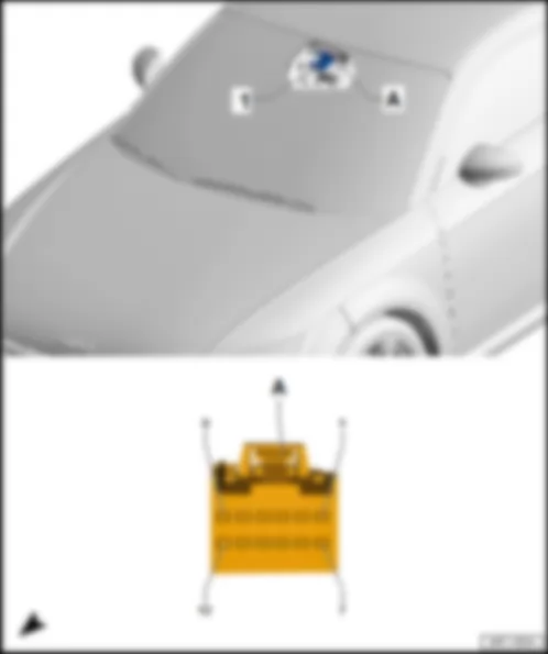
AUDI TT 2016 Fitting location, roof electronics control unit J528Fitting location, roof electronics control unit -J528- |
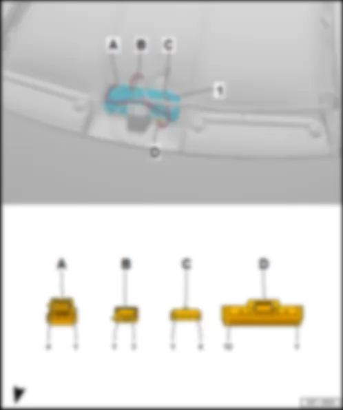
| In front roof module -WX3- . | | 1 - | Roof electronics control unit -J528- | | B - | 3-pin connector -T3b- , black | | q | for garage door operating unit -E284- | | D - | 12-pin connector -T12c- , black | | q | for roof electronics control unit -J528- |
| Connector assignment of roof electronics control unit -J528- | | -T12c- (D) | Designation | | -T12c- (D) | Designation | | 1 | | | 7 | Automatic anti-dazzle interior mirror -Y7- | | 2 | | | 8 | Terminal 30, from fuse holder C -SC- | | 3 | | | 9 | Onboard supply control unit -J519- | | 4 | Airbag control unit -J234- | | 10 | Terminal 31, to 639 earth point on left A-pillar | | 5 | Airbag control unit -J234- | | 11 | Terminal 58s, to B731 connection 1 (58s) in main wiring harness | | 6 | Airbag control unit -J234- | | 12 | Terminal 30, from B559 positive connection 1 (30g) in main wiring harness |
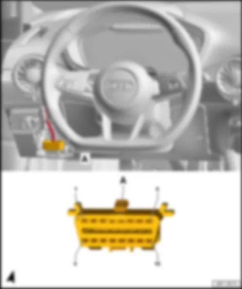
AUDI TT 2016 Fitting location, data bus diagnostic interface J533Fitting location, data bus diagnostic interface -J533- |
| Behind dash panel on driver side. | | | | | 1 - | Data bus diagnostic interface -J533- | | Connector assignment, data bus diagnostic interface -J533- | | | | | -T20a- (A) | Designation | | -T20a- (A) | Designation | | 1 | Terminal 30, from terminal 15 voltage supply relay -J329- | | 11 | Terminal 31, to 376 earth connection 11 in main wiring harness
370 earth connection 5 in main wiring harness
639 earth point on left A-pillar | | 2 | | | 12 | | | 3 | LIN bus, to B711 connection 6 (LIN bus) in main wiring harness | | 13 | LIN bus, to steering column electronics control unit -J527- | | 4 | | | 14 | Terminal 15, from B277 positive connection 1 (15a) in main wiring harness
onboard supply control unit -J519- | | 5 | Comfort CAN bus, low to B407 connection 2 (comfort CAN bus, low) in main wiring harness | | 15 | Comfort CAN bus, high to B398 connection 2 (comfort CAN bus, high) in main wiring harness | | 6 | Powertrain CAN bus, low to B390 connection 1 (powertrain CAN bus, low) in main wiring harness | | 16 | Powertrain CAN bus, high to B383 connection 1 (powertrain CAN bus, high) in main wiring harness | | 7 | Extended CAN bus, low to B109 connection 1 (extended CAN bus, low) in main wiring harness | | 17 | Extended CAN bus, high to B108 connection 1 (extended CAN bus, high) in main wiring harness | | 8 | Chassis/dash panel insert CAN bus, low
B677 connection 2 (chassis/dash panel insert CAN bus, low) in main wiring harness | | 18 | Chassis/dash panel insert CAN bus, high
B673 connection 2 (chassis/dash panel insert CAN bus, high) in main wiring harness | | 9 | Diagnosis CAN bus, low to B714 connection 1 (diagnosis CAN bus, low) in main wiring harness
diagnostic connection -U31- | | 19 | Diagnosis CAN bus, high to B713 connection 1 (diagnosis CAN bus, high) in main wiring harness
diagnostic connection -U31- | | 10 | Infotainment CAN bus, low to B421 connection 1 (infotainment CAN bus, low) in main wiring harness | | 20 | Infotainment CAN bus, high to B415 connection 1 (infotainment CAN bus, high) in main wiring harness |
AUDI TT 2016 Fitting location, fuel pump control unit J538 | 1 - | Fuel pump control unit -J538- | | q | with fuel gauge sender -G- , fuel system pressurisation pump -G6- , fuel gauge sender 2 -G169- | | B - | 6-pin connector -T6i- , black | | q | models with diesel engine only |
| Connector assignment, fuel pump control unit -J538- | | | | | -T5o- (A) | Designation | | 1 | Fuel system pressurisation pump -G6- | | 2 | Fuel system pressurisation pump -G6- | | 3 | Terminal 30, from fuse holder B -SB- | | 4 | Terminal 31, to 375 earth connection 10 in main wiring harness
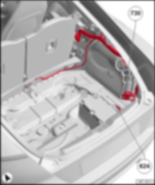
730 earth point 1 on rear right wheel housing | | 5 | Engine control unit -J623- |
| -T6i- (B) | Designation | | 1 | Fuel system pressurisation pump -G6- | | 2 | Fuel system pressurisation pump -G6- | | 3 | Fuel system pressurisation pump -G6- | | 4 | Terminal 31, to 375 earth connection 10 in main wiring harness
730 earth point 1 on rear right wheel housing | | 5 | Terminal 30, from fuse holder B -SB- | | 6 | Engine control unit -J623- |
AUDI TT 2016 Fitting location, chip card reader control unit J676 | 1 - | Chip card reader control unit -J676- | | A - | 4-pin connector -T4ca- , brown | | B - | 10-pin connector -T10u- , black | | C - | 2-pin connector -T2gy- , yellow |
| Connector assignment, chip card reader control unit -J676- | | | | | -T4ca- (A) | Designation | | -T2gy- (C) | Designation | | 1 | USB connection holder -R193- | | 1 | Dedicated short-range communication aerial -R269- | | 2 | USB connection holder -R193- | | 2 | Dedicated short-range communication aerial -R269- | | 3 | USB connection holder -R193- | | | | | 4 | USB connection holder -R193- | | | | | 5 | USB connection holder -R193-
Screen earth | | | |
| -T10u- (B) | Designation | | -T10u- (B) | Designation | | 1 | Traffic data aerial -R173- | | 6 | LIN bus, to B699 connection 4 (LIN bus) in main wiring harness
Climatronic control unit -J255- | | 2 | Traffic data aerial -R173- | | 7 | Traffic data aerial -R173- | | 3 | Traffic data aerial -R173- | | 8 | Traffic data aerial -R173- | | 4 | Traffic data aerial -R173- | | 9 | Terminal 30, from B318 positive connection 4 (30a) in main wiring harness
fuse holder C -SC- | | 5 | | | 10 | Terminal 31, to 477 earth connection (audio) in main wiring harness
687 earth point 1 on centre tunnel |
AUDI TT 2016 Fitting location, seat occupied recognition control unit J706Fitting location, seat occupied recognition control unit -J706- |
| under front passenger seat. | | 1 - | Seat occupied recognition control unit -J706- | | B - | 3-pin connector -T3ad- |
| Connector assignment, seat occupied recognition control unit -J706- | | -T10v- (A) | Designation | | -T3ad- (B) | Designation | | 1 | | | 1 | Terminal 15, from fuse holder C -SC- | | 2 | Screen earth | | 2 | Airbag control unit -J234- | | 3 | Terminal 31, to 35 earth point under front passenger seat | | 3 | Terminal 31, to 95 earth connection 1 in seat adjustment wiring harness | | 4 | Terminal 31, to 136 earth connection 2 in seat heating wiring harness | | | | | 5 | | | | | | 6 | Heated front passenger seat -Z8- | | | | | 7 | | | | | | 8 | Heated front passenger seat -Z8- | | | | | 9 | | | | | | 10 | Positive supply, from O14 connection 3 in seat heating wiring harness | | | |
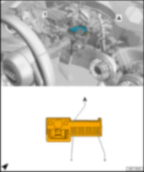
AUDI TT 2016 Fitting location, control unit for electronic steering column lock J764Fitting location, control unit for electronic steering column lock -J764- |
| On top of the steering column. | | 1 - | Control unit for electronic steering column lock -J764- | | Connector assignment of control unit for electronic steering column lock -J764- | | | |
| -T4l- (A) | Designation | | 1 | Comfort high CAN bus, to B397 connection 1 (comfort high CAN bus) in main wiring harness | | 2 | Comfort low CAN bus to B406 connection 1 (comfort low CAN bus) in main wiring harness | | 3 | Terminal 30, from fuse holder C -SC- | | 4 | Terminal 31, to 639 earth point on left A-pillar |
AUDI TT 2016 Fitting location, control unit 1 for information electronics J794Fitting location, control unit 1 for information electronics -J794- |
| | | | 1 - | Control unit 1 for information electronics -J794- | | A - | 2-pin connector -T2gg- , aerial connection, LTE, Bordeaux, LTE aerial 1 -R297- | | D - | 8-pin connector -T8q- , black | | F - | 12-pin connector -T12n- , green | | H - | 8-pin connector -T8p- , brown | | K - | 4-pin connector -T4aa- , grey, display unit for front information display and operating unit control unit -J685- | | M - | 4-pin connector -T4bl- , aerial connection, AM/FM, white, aerial amplifier -R24- | | Connector assignment, control unit 1 for information electronics -J794- | | | | | -T8g- (D) | Designation | | -T8p- (H) | Designation | | 9 | | | 1 | Rear right treble loudspeaker -R16-
Rear right bass loudspeaker -R17- | | 10 | Centre loudspeaker -R208- | | 2 | Front right treble loudspeaker -R22-
Front right bass loudspeaker -R23- | | 11 | | | 3 | Front left treble loudspeaker -R20-
Front left bass loudspeaker -R21- | | 12 | | | 4 | Rear left treble loudspeaker -R14-
Rear left bass loudspeaker -R15- | | 13 | | | 5 | Rear right treble loudspeaker -R16-
Rear right bass loudspeaker -R17- | | 14 | Centre loudspeaker -R208- | | 6 | Front right treble loudspeaker -R22-
Front right bass loudspeaker -R23- | | 17 | Terminal 31, to 383 earth connection 18 in main wiring harness
687 earth point 1 on centre tunnel | | 7 | Front left treble loudspeaker -R20-
Front left bass loudspeaker -R21- | | 18 | Terminal 30, from fuse holder C -SC- | | 8 | Rear left treble loudspeaker -R14-
Rear left bass loudspeaker -R15- |
| -T12m- (E) | Designation | | -T12n- (F) | Designation | | 1 | Display and operation CAN bus, low
B751 connection 1 (display and operation CAN bus, low)
display unit for front information display and operating unit control unit -J685-
multimedia system operating unit -E380- | | 1 | Connection for external audio sources -R199- | | 2 | Multimedia system operating unit -E380- | | 2 | Connection for external audio sources -R199- | | 3 | Ring circuit break diagnostic wire
B444 connection 1 (diagnosis) in main wiring harness | | 3 | Connection for external audio sources -R199- | | 4 | | | 4 | | | 5 | Telephone bracket -R126-
B478 connection 14 in main wiring harness | | 5 | | | 6 | Infotainment CAN bus, high
B415 connection 1 (infotainment CAN bus, high) in main wiring harness | | 6 | | | 7 | Display and operation CAN bus, high
B750 connection 1 (display and operation CAN bus, high)
display unit for front information display and operating unit control unit -J685-
multimedia system operating unit -E380- | | 7 | Connection for external audio sources -R199- | | 8 | Multimedia system operating unit -E380- | | 8 | Screen earth, connection for external audio sources -R199- | | 9 | | | 9 | | | 10 | | | 10 | | | 11 | Telephone bracket -R126- | | 11 | | | 12 | Infotainment CAN bus, low
B421 connection 1 (infotainment CAN bus, low) in main wiring harness | | 12 | |
| -T12i- (G) | Designation | | -T12i- (G) | Designation | | 1 | Telephone microphone -R38- , coupé
Belt microphone control unit -J886- , roadster | | 7 | Telephone microphone -R38- , coupé
Screen earth, control unit for seat belt microphone -J886- , roadster | | 2 | Screen earth, control unit for seat belt microphone -J886- , roadster | | 8 | Control unit for seat belt microphone -J886- , roadster | | 3 | | | 9 | | | 4 | | | 10 | | | 5 | | | 11 | | | 6 | Reversing camera system control unit -J772- | | 12 | Reversing camera system control unit -J772- |
AUDI TT 2016 Fitting location Main beam assist control unit J844Fitting location Main beam assist control unit -J844- |
| 1 - | Main beam assist control unit -J844- | | Connector assignment of main beam assist control unit -J844- | | -T8a- (A) | Designation | | -T8a- (A) | Designation | | 1 | Terminal 15, from fuse holder C -SC- | | 5 | Mirror dimming signal line, to B428 connection 2 (mirror signal) in main wiring harness | | 2 | Terminal 31, to 639 earth point on left A-pillar | | 6 | | | 3 | Extended high CAN bus, to B108 connection 1 (extended high CAN bus) in main wiring harness | | 7 | | | 4 | Mirror dimming signal line, to B427 connection 1 (mirror signal) in main wiring harness | | 8 | Extended CAN bus, low, from B109 connection 1 (extended CAN bus, low) in main wiring harness |
AUDI TT 2016 Fitting location, exhaust flap control unit J883Fitting location, exhaust flap control unit -J883- |
| On exhaust pipe, near front cross member. | | | | | 1 - | Exhaust flap control unit -J883- | | Connector assignment, exhaust flap control unit -J883- | | | |
| -T5h- (A) | Designation | | 1 | D109 connection 7 in engine compartment wiring harness
engine control unit -J623- | | 2 | Engine control unit -J623- | | 3 | 419 earth connection 11 in engine compartment wiring harness
engine control unit -J623- | | 4 | Engine control unit -J623- | | 5 | Engine control unit -J623- |
AUDI TT 2016 Fitting location, control unit for seat belt microphone J886Fitting location, control unit for seat belt microphone -J886- |
| Under front of centre console. | | | | | 1 - | Control unit for seat belt microphone -J886- | | Connector assignment, control unit for seat belt microphone -J886- | | | | | -T32d- (A) | Designation | | -T32d- (A) | Designation | | 1 | Microphone unit in front roof module -R164-
Telephone microphone -R38- | | 17 | Microphone unit in front roof module -R164-
Telephone microphone -R38- | | 2 | Microphone 1 on driver side -R224- | | 18 | Microphone 1 on front passenger side -R227- | | 3 | Microphone 1 on driver side -R224- | | 19 | Microphone 1 on front passenger side -R227- | | 4 | Microphone 1 on driver side -R224- | | 20 | Microphone 1 on front passenger side -R227- | | 5 | Microphone 1 on driver side -R224- | | 21 | Microphone 1 on front passenger side -R227- | | 6 | Microphone 1 on driver side -R224- | | 22 | Microphone 1 on front passenger side -R227- | | 7 | Microphone 1 on driver side -R224- | | 23 | Microphone 1 on front passenger side -R227- | | 8 | Terminal 31, to 372 earth connection 7 in main wiring harness
687 earth point 1 on centre tunnel | | 24 | | | 9 | Control unit 1 for information electronics -J794- | | 25 | Control unit 1 for information electronics -J794- | | 10 | Control unit 1 for information electronics -J794- | | 26 | Control unit 1 for information electronics -J794- | | 11 | | | 27 | | | 12 | | | 28 | | | 13 | | | 29 | | | 14 | Terminal 30, from B318 positive connection 4 (30a) in main wiring harness
fuse holder C -SC-
fuse 2 -S132- | | 30 | | | 15 | | | 31 | | | 16 | Infotainment CAN bus, high
B415 connection 1 (infotainment CAN bus, high) in main wiring harness
data bus diagnostic interface -J533- | | 32 | Infotainment CAN bus, low
B421 connection 1 (infotainment CAN bus, low) in main wiring harness
data bus diagnostic interface -J533- |
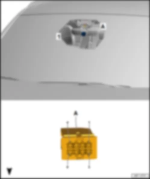
AUDI TT 2016 Fitting location, front camera for driver assist systems R242Fitting location, front camera for driver assist systems -R242- |
| | | | 1 - | Front camera for driver assist systems -R242- | | Fitting location, front camera for driver assist systems -R242- | | | | | -T12b- (A) | Designation | | -T12b- (A) | Designation | | 1 | | | 7 | | | 2 | Extended CAN bus, low to B109 connection 1 (extended CAN bus, low) in main wiring harness
data bus diagnostic interface -J533- | | 8 | Extended CAN bus, high to B108 connection 1 (extended CAN bus, high) in main wiring harness
data bus diagnostic interface -J533- | | 3 | | | 9 | | | 4 | Windscreen heater for lane departure warning -Z67- | | 10 | | | 5 | Terminal 31, to 369 earth connection 4 in main wiring harness
370 earth connection 5 in main wiring harness
639 earth point on left A-pillar | | 11 | | | 6 | Terminal 15, from B279 positive connection 3 (15a) in main wiring harness | | 12 | |
AUDI TT 2016 | 1 - | Convertible roof actuation motor -V82- /convertible roof actuation motor 2 -V576- | | 10-pin connector -T10s- , black/10-pin connector -T10g- , black |
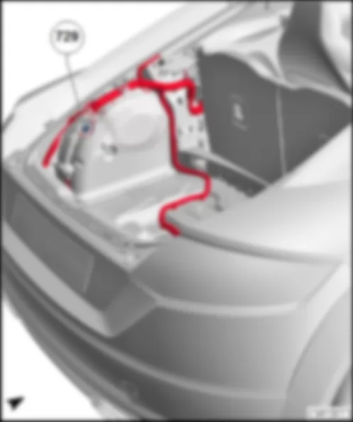
| Connector assignment, convertible roof actuation motor -V82- /convertible roof actuation motor 2 -V576- | | | | | -T10s- (A) | Designation | | -T10g- (A) | Designation | | 1 | | | 1 | | | 2 | | | 2 | | | 3 | | | 3 | | | 4 | | | 4 | | | 5 | Terminal 31, to 387 earth connection 22 in main wiring harness
368 earth connection 3 in main wiring harness
729 earth point on rear left wheel housing | | 5 | Terminal 31, to 387 earth connection 22 in main wiring harness
368 earth connection 3 in main wiring harness
729 earth point on rear left wheel housing | | 6 | M32 connection 1 in convertible roof actuation wiring harness
convertible roof actuation control unit -J256- | | 6 | M32 connection 1 in convertible roof actuation wiring harness
convertible roof actuation control unit -J256- | | 7 | Convertible roof actuation control unit -J256- | | 7 | Convertible roof actuation control unit -J256- | | 8 | Convertible roof actuation control unit -J256- | | 8 | Convertible roof actuation control unit -J256- | | 9 | Convertible roof actuation control unit -J256- | | 9 | Convertible roof actuation control unit -J256- | | 10 | Convertible roof actuation control unit -J256- | | 10 | Convertible roof actuation control unit -J256- |
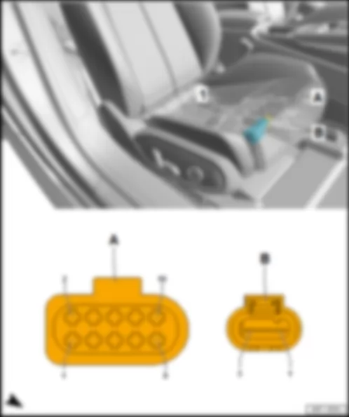
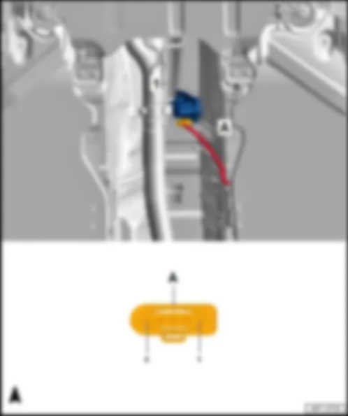
AUDI TT 2016 Fitting location, cabriolet windbreak motor V186Fitting location, cabriolet windbreak motor -V186- |
| On rear of windbreak in centre. | | | | | 1 - | Cabriolet windbreak motor -V186- | | Connector assignment, cabriolet windbreak motor -V186- | | | |
| -T3bi- (A) | Designation | | 1 | | | 2 | Convertible roof actuation control unit -J256- | | 3 | Convertible roof actuation control unit -J256- |
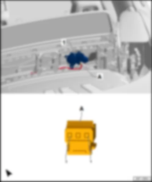
AUDI TT 2016 Fitting location, convertible roof lock motor V223Fitting location, convertible roof lock motor -V223- |
| Behind cover near front interior light -W1- . | | | | | 1 - | Convertible roof lock motor -V223- | | Connector assignment, convertible roof lock motor -V223- | | | | | -T4ch- (A) | Designation | | 1 | Convertible roof actuation control unit -J256- | | 2 | | | 3 | Convertible roof actuation control unit -J256- | | 4 | |
| |
| | | | |
| |
| |

