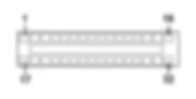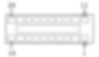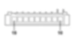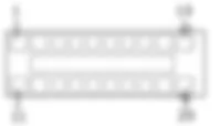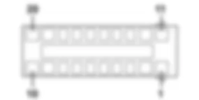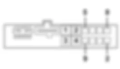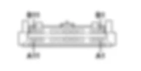
Components - RADIO - Fiat DOBLO 1.4 8v Da 10/2000
| Component code | Description | Reference to the assembly |
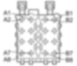
| B001 | JUNCTION UNIT | |
| B2 | JUNCTION UNIT UNDER DASHBOARD | |
| C15 | DASHBOARD EARTH, DRIVER''S SIDE | |
| D20 | DASHBOARD/REAR COUPLING | |
| D097 | SHORT CIRCUITING COUPLING | |
| H001 | IGNITION SWITCH | |
| M001 | BODY COMPUTER | |
| P20 | RADIO | |
| P25 | AERIAL POWER SUPPLY | |
| P37 | LEFT FRONT SPEAKER IN DASHBOARD | |
| P38 | RIGHT FRONT SPEAKER IN DASHBOARD |
The vehicle may be equipped with a radio system as an option.The system consists of the following components:- radio (CD/tape player);- radio supply leads;- two front speakers on the dashboard;- aerial;- coaxial aerial lead.The radio system is equipped with a communication protocol with an electronic unit that manages the electrical system (body computer).When the radio is supplied, the body computer reads the radio code and determines whether to activate it or not.The radio circuit is supplied with the key ON and via a direct supply from the battery (which allows tuning, safety codes, etc. to be stored).The above line is protected by two fuses in the engine compartment control unit and the underfacia junction unit.
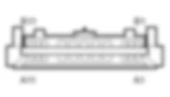
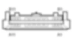
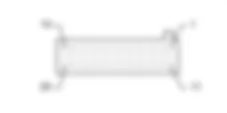
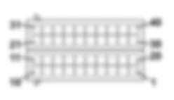
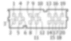
The operation of ratio system P20 is controlled by the body computer by lines leaving pins 5 and 17 connector E of junction unit B02 and entering pins 1 and 3 of connector A of radio P20.The radio is supplied directly (pin 7 connector A) by the battery via a line from fuse F1 contained in engine compartment junction unit B01 and protected by fuse 39 in under-dashboard junction unit B02.Radio P20 receives ignition-controlled power (INT) (pin 4 of connector A) via the line of fuse F49 from under-dashboard junction unit B1 .Radio P20 receives a power supply at pin 6 of connector A with side lights on for interior lighting via a line controlled by body computer M01 and protected by fuse F51 of junction unit B02.The following cables with signals for the speakers leave radio connector B:- right front side on dashboard P38 from pins 3 and 4 via short-circuiting junction D97 D;- left front side on dashboard P37 from pins 5 and 6 via short-circuiting junction D97 B;Pin 5 connector A is connected to the amplifier of aerial P25 while pin 8 connector A is earthed.Speaker P38 assumes a dual coil configuration when mobile phone wiring is installed.


