Wiring Diagram - STARTING AND RECHARING - Fiat ULYSSE 2.2 16V JTD fino a 04/03
Components - STARTING AND RECHARING - Fiat ULYSSE 2.2 16V JTD fino a 04/03
| Component code | Description | Reference to the assembly |
| A001 | Battery | 5530B |
| A010 | Alternator | 5530A |
| A020 | Starter motor | 5520B |
| B001 | Engine compartment junction unit | 5505A |
| C010 | Left front earth | - |
| C011 | Right front earth | - |
| C020 | Passenger dashboard earth | - |
| D007 | Alternator coupling | - |
| E050 | Instrument panel | 5560B |
| H001 | Ignition switch | 5520A |
| M001 | Body computer | 5505A |
| M010 | Engine management control unit | 1060G |
| M015 | Heater plugs control unit | - |
| M140 | Warning lights and milometer control unit (NSO) | - |
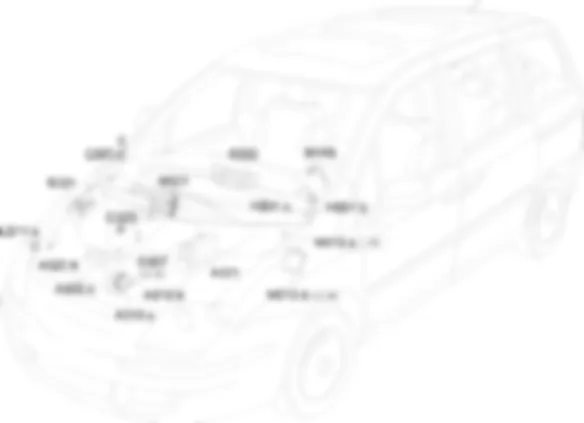
Location Components - STARTING AND RECHARING - Fiat ULYSSE 2.2 16V JTD fino a 04/03
Components - STARTING AND RECHARING - Fiat ULYSSE 2.2 16V JTD fino a 04/03
| Component code | Description | Reference to the assembly |
| A001 | Battery | 5530B |
| A010 | Alternator | 5530A |
| A020 | Starter motor | 5520B |
| B001 | Engine compartment junction unit | 5505A |
| C010 | Left front earth | - |
| C011 | Right front earth | - |
| C020 | Passenger dashboard earth | - |
| D007 | Alternator coupling | - |
| E050 | Instrument panel | 5560B |
| H001 | Ignition switch | 5520A |
| M001 | Body computer | 5505A |
| M010 | Engine management control unit | 1060G |
| M015 | Heater plugs control unit | - |
| M140 | Warning lights and milometer control unit (NSO) | - |
Description - STARTING AND RECHARING - Fiat ULYSSE 2.2 16V JTD fino a 04/03
The ignition and recharging circuit comprises the battery, starter motor and alternator.The battery (12V) is the lead, low maintenance type.The starter motor consists of a d.c. motor supplied by the battery and an excitation electromagnet.When the ignition key is turned as far as it will go (D), the motor windings are supplied to generate the electromagnetic forces that are used to turn the starter motor pinion. This simultaneously activates the electromagnet that operates the mechanism that causes the pinion to mesh with the flywheel ring gear and thus turn the crankshaft.The alternator recharges the battery during normal engine rotation.The alternator shaft (rotor) is turned by the crankshaft via a belt. When supplied by an excitation current, the rotor generates a magnetic field that sets up an alternating current in the fixed winding (stator).A rectifying diode bridge on the back of the alternator allows the alternating current to be rectified to a direct current that is sent to recharge the battery.A voltage governor, also built into the alternator, maintains the power supply at a constant voltage (14 V) throughout the load variation and engine speed ranges.
Operational Description - STARTING AND RECHARING - Fiat ULYSSE 2.2 16V JTD fino a 04/03
The battery A001, supplies the ignition switch H001, through the line protected by fuse MF7 of the engine compartment junction unit B001, at pin 1 connector A.When the ignition is turned to position M, the alternator A010 informs the body computer node M001, from pin D+, at pin 11 connector M of the battery charge state.The "battery recharging" warning light is switched on by the milometer warning lights node M140 which communicates with the instrument panel E050 and the body computer node M001 via the CAN.The ignition switch also provides the junction unit B001 with an igition-controlled supply (from pin 2 connector A at pin 9 connector C) and the body computer node M001 (from pin 1 connector B at pin 1 connector C).When the ignition key is turned to position D, the supply, from pin 3 connector A of H001, reaches the starter motor A020 at pin 50. The internal contact is closed, providing the internal motor with a direct battery supply at pin 30 of the starter motor.When the ignition key is turned back to position M, the starter motor A020 internal contact opens, interrupting the direct battery supply. The alternator A010 recharges the battery A001 from pin B+.< B > 2.0 16V < /B >When the ignition key is turned back to position M, the starter motor A020 internal contact opens, interrupting the direct battery supply. The alternator A010 recharges the battery A001 from pin B+.< B > 2.0 16V 2.2 16V < /B >The alternator communicates the battery charge from pin D+ to the heater plugs control unit M015.


