ANTI-THEFT
Forced Entry Wiring Diagram for Volvo XC70 2004
 https://portal-diagnostov.com/license.html
Automotive Electricians Portal FZCO
Automotive Electricians Portal FZCO
https://portal-diagnostov.com/license.html
https://portal-diagnostov.com/license.html
Automotive Electricians Portal FZCO
Automotive Electricians Portal FZCO
List of elements for Forced Entry Wiring Diagram for Volvo XC70 2004:
- (in left side rear window)
- (in right side rear window)
- A11
- A12
- A13
- A14
- A15
- A16
- Air conditioning system
- Alarm siren (at inside front of front right wheelwell)
- B12
- B17
- B18
- C18
- Central electronic module
- Climate control module
- Combination instrument panel dim
- Computer data lines system
- D20
- Front mass movement sensor (center of roof)
- Fuse c38 5a
- G47 (at left rear of passenger's compartment, near floor)
- G66 (below driver's seat, near rocker panel)
- G67 (below passenger's seat, near rocker panel)
- G72 (at left rear of passenger's compartment, near floor)
- G93 (at rear of left fender)
- G94 (at rear of right fender)
- G98 (at front center of headliner)
- G99 (above left rear window)
- Hood alarm contact (at left front of engine compt)
- Hot at all times
- Inclination sensor module (left rear corner of cargo compartment)
- Key
- Left front door control module
- Left front door lock unit
- Left glass breakage sensor (optional)
- Left rear door lock unit
- Nca
- Passenger compartment relay/fuse box (at left end of dash)
- Pnk
- Rear electronic module (at left rear corner of cargo compartment, on cargo compartment relay/fuse box)
- Red
- Reduced alarm switch
- Right front door control module
- Right front door lock unit
- Right glass breakage sensor (optional)
- Right rear door lock unit
- Solar sensor, indicator alarm & electronic immobilizer (on top center of dash)
- Tailgate glass breakage sensor (optional) (in tailgate window)
- Trunk lid lock unit
- Ulk
- Upper electronic module (above center of windshield)
- W/ subwoofer
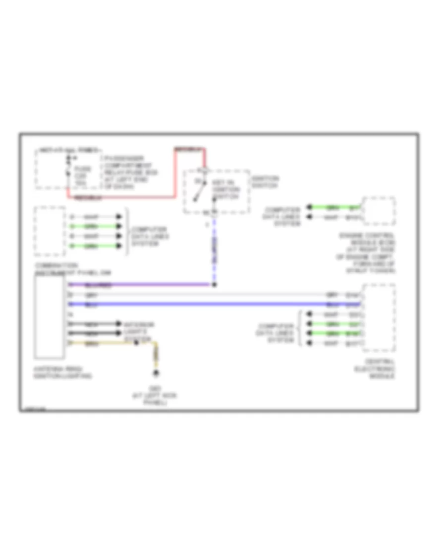
Immobilizer Wiring Diagram for Volvo XC70 2004
List of elements for Immobilizer Wiring Diagram for Volvo XC70 2004:
- Antenna ring/ ignition lighting
- B13
- B17
- B18
- Central electronic module
- Combination instrument panel dim
- Computer data lines system
- D13
- D14
- Engine control module (ecm) (at right side of engine compt, forward of strut tower)
- Fuse c25 10a
- G83 (at left kick panel)
- Hot at all times
- Ignition switch
- Interior lights system
- Key in ignition switch
- Nca
- Passenger compartment relay/fuse box (at left end of dash)

 Čeština
 Dansk
Dansk Deutsch
 Ελληνικά
 English
 English
 Español
 Suomi
Suomi Français
 Français
 עברית
עברית Hrvatski
 Magyar
 Italiano
 日本語
日本語 한국어
한국어 Nederlands
 Polski
 Português
 Português
 Русский
 Slovenčina
 Slovenščina
 Svenska
 Türkçe
 中文 (中国)