ENGINE PERFORMANCE
3.5L
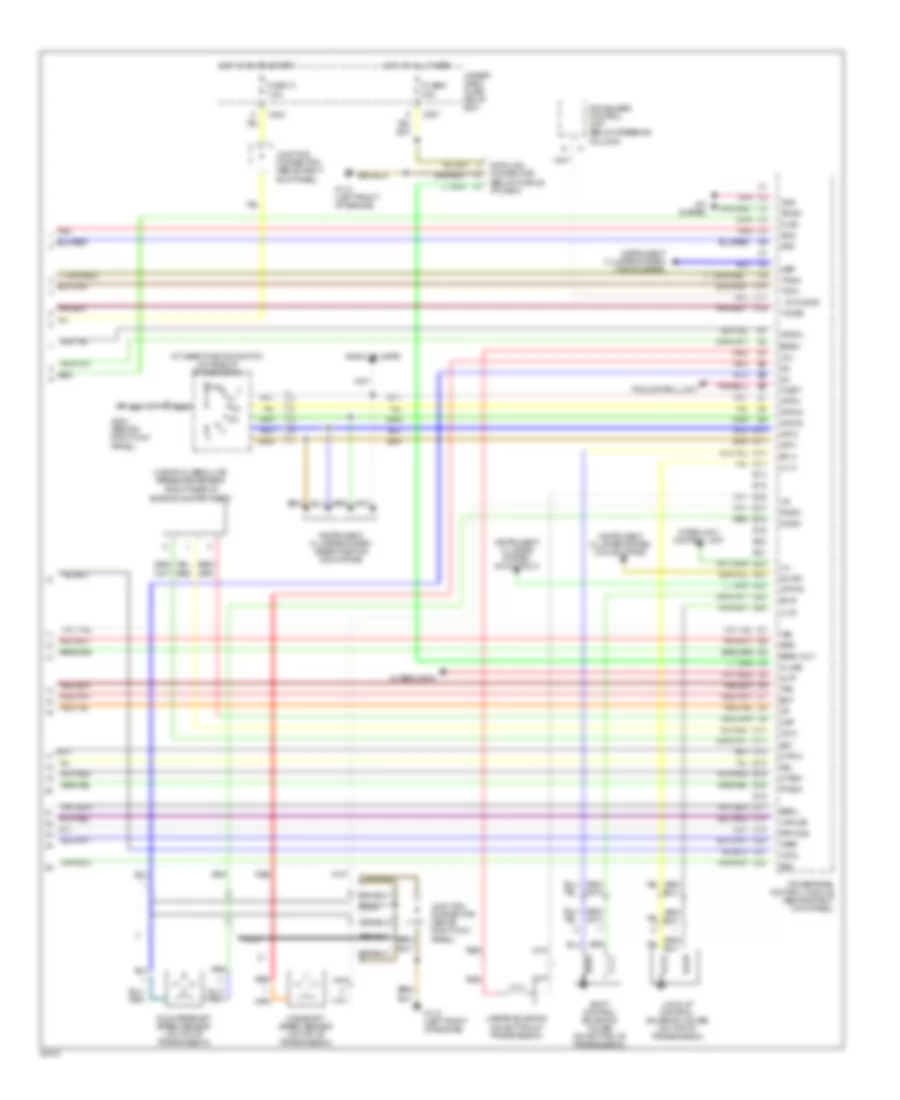
3.5L, Wiring Diagram (3.5RL 3.5L Wiring Diagram 1 Of 4) for Acura 3.5RL 1996

List of elements for 3.5L, Wiring Diagram (3.5RL 3.5L Wiring Diagram 1 Of 4) for Acura 3.5RL 1996:
3.5L, Wiring Diagram (3.5RL 3.5L Wiring Diagram 2 Of 4) for Acura 3.5RL 1996
List of elements for 3.5L, Wiring Diagram (3.5RL 3.5L Wiring Diagram 2 Of 4) for Acura 3.5RL 1996:
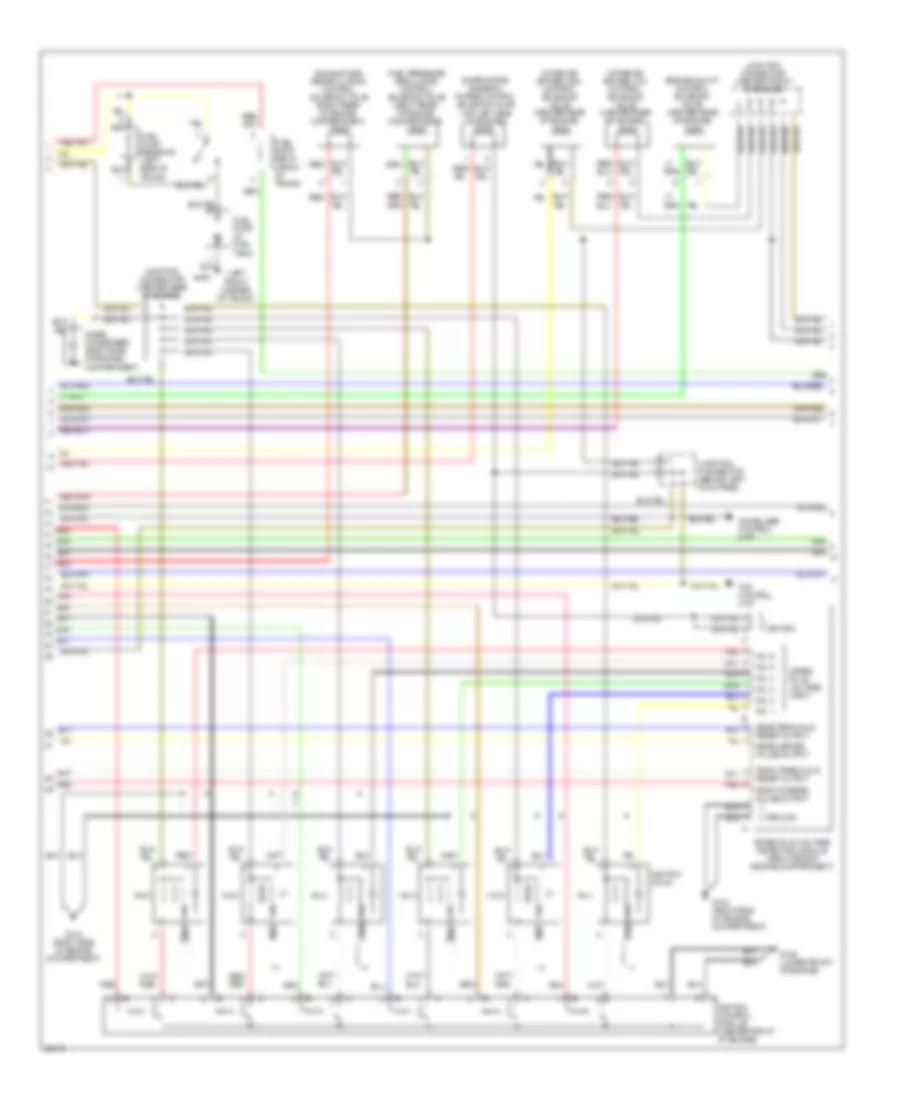
3.5L, Wiring Diagram (3.5RL 3.5L Wiring Diagram 3 Of 4) for Acura 3.5RL 1996
List of elements for 3.5L, Wiring Diagram (3.5RL 3.5L Wiring Diagram 3 Of 4) for Acura 3.5RL 1996:
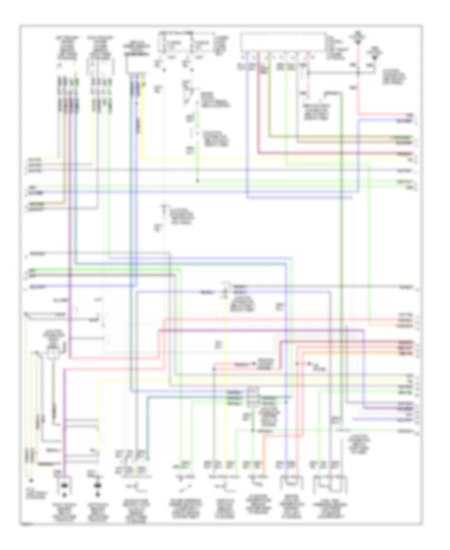
3.5L, Wiring Diagram (3.5RL 3.5L Wiring Diagram 4 Of 4) for Acura 3.5RL 1996
List of elements for 3.5L, Wiring Diagram (3.5RL 3.5L Wiring Diagram 4 Of 4) for Acura 3.5RL 1996: