ENGINE PERFORMANCE
3.5L
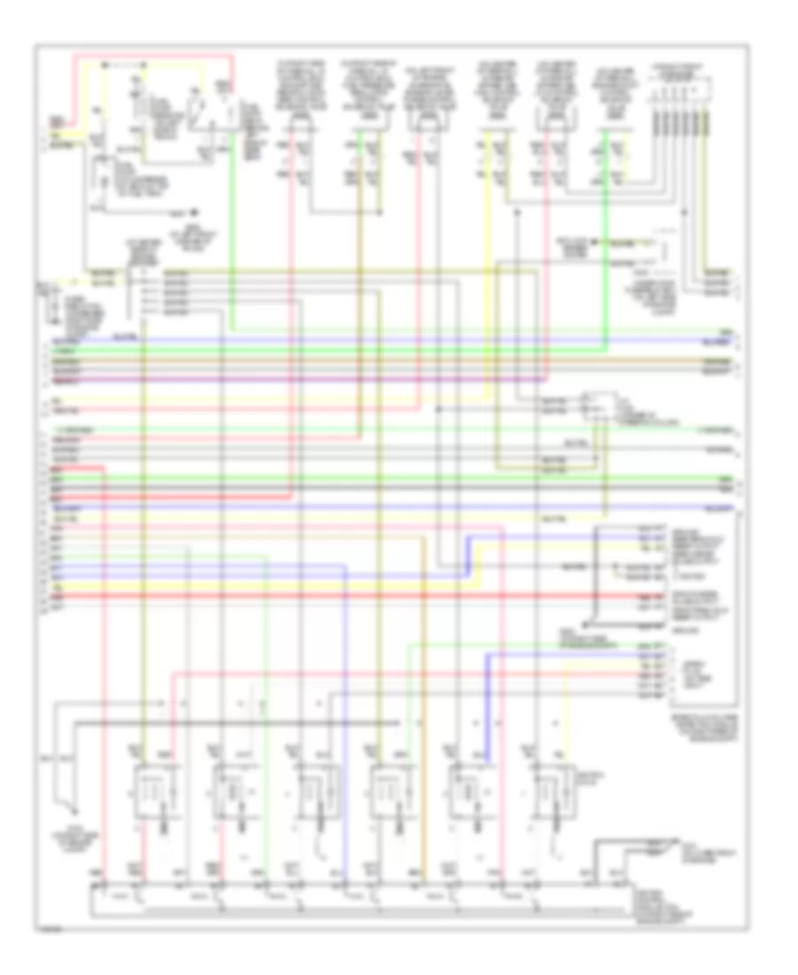
3.5L, Engine Performance Wiring Diagram (1 of 4) for Acura 3.5RL 2004

List of elements for 3.5L, Engine Performance Wiring Diagram (1 of 4) for Acura 3.5RL 2004:
- 2wbs
- A10
- A11
- A12
- A13
- A14
- A15
- A16
- A17
- A18
- A19
- A20
- A21
- A22
- A23
- A24
- A25
- A26
- Acc
- Air conditioning system
- Anti- theft system
- B10
- B11
- B12
- B13
- B14
- B15
- B16
- C404
- C405
- C406
- C501
- C651
- Ckp 1
- Ckp 2
- Ckp1m
- Ckp1p
- Ckp2m
- Ckp2p
- Crankshaft position/cylinder position (ckp/cyp) sensor
- Cyp 1
- Cyp 2
- Cyp1p
- Cyp2p
- Evaporative emission (evap) by-pass solenoid valve (under left rear of vehicle)
- Evaporative emission (evap) control canister vent shut valve (under left rear of vehicle)
- Flr1
- Fprcs
- Fuel injectors
- Fuse 14 starter signal 7.5a
- Fuse 20 ecu 20a
- Fuse 22 fuel pump 20a
- Fuse 25 ig coil 30a
- Fuse 6 ecu 20a
- G101 (on top left of engine)
- Hot at all times
- Hot in on or start
- Hot in start
- Iabcs1
- Iabcs2
- Iacv
- Idle air control (iac) valve (on left side of throttle body base)
- Ign coil 1
- Ign coil 2
- Ign coil 3
- Ign coil 4
- Ign coil 5
- Ign coil 6
- Igp1
- Igp2
- Inj1
- Inj2
- Inj3
- Inj4
- Inj5
- Inj6
- J/c c146 (at left side of engine compt)
- J/c c456 (below right side of dash)
- Lg1
- Lg2
- Lpo2shtc
- Mcs
- Mfpls l
- Mfpls r
- Mil
- Pcs
- Pg1
- Pg2
- Pgm-fi main relay (behind dash, right of steering column, on bracket)
- Phrst l
- Phrst r
- Pnk
- Powertrain control module (pcm) (below front passenger's footrest)
- Psp sw
- Red
- Rpo2shtc
- Secondary heater oxygen sensor (secondary ho2s) (on side of catalytic converter)
- Sho2s
- So2sgnd
- So2shtc
- Under-dash fuse/ relay box (behind left kick panel)
- Vss
- Vsv
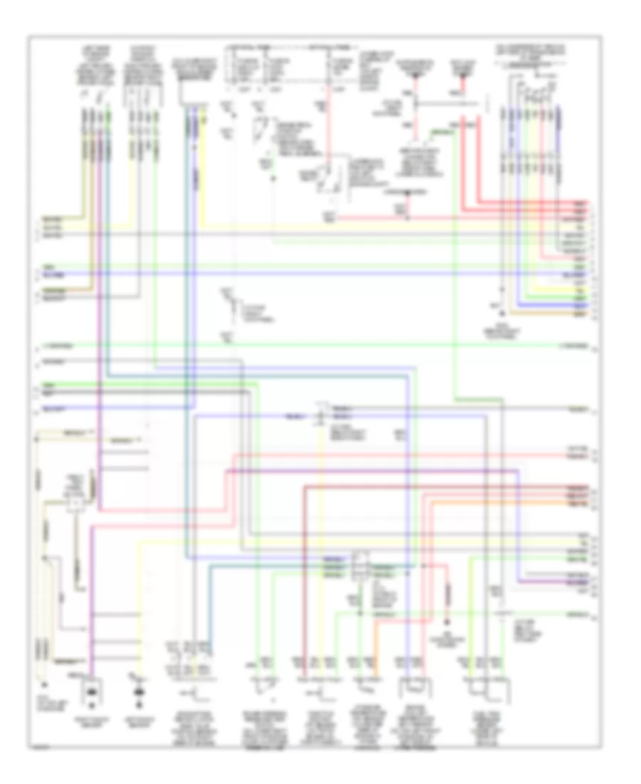
3.5L, Engine Performance Wiring Diagram (2 of 4) for Acura 3.5RL 2004
List of elements for 3.5L, Engine Performance Wiring Diagram (2 of 4) for Acura 3.5RL 2004:
- (at center rear of engine) j/c c106
- (at right front of engine) j/c c114
- (on center of firewall) engine mount control solenoid valve
- (on center of firewall) intake air bypass (iab) high control solenoid valve
- (on center of firewall) intake air bypass (iab) low control solenoid valve
- (on left front of engine)
- (on right side of firewall, in control box) exhaust gas recirculation (egr) control solenoid valve
- (on right side of firewall, in control box) fuel pressure regulator control solenoid valve
- A6 red
- Anti-lock brakes system
- B4 red
- C302
- Evaporative emission (evap) purge control solenoid valve
- Front misfire pulse output
- Front peak hold reset output
- Fuel pump (on underside of vehicle, top of fuel tank)
- Fuel pump relay (behind left side of rear seat)
- Fuel pump resistor (on left side of trunk)
- G102 (on right side of engine compt)
- G151 (at lower front of engine)
- G202 (on right side of engine compt)
- G652 (at left front corner of trunk)
- Ground
- Ground rear peak hold reset output rear misfire pulse output
- Ignition
- Ignition coils
- Ignition control module (icm) (on right side of engine compt)
- J/c c421 (at base of steering column)
- Noise reduction condenser (right side of engine compt)
- Pnk
- Red
- Spark plug voltage detection module (on right rear of engine compt)
- Spark plug voltage input
- Under-hood fuse/relay box (on left side of engine compt)
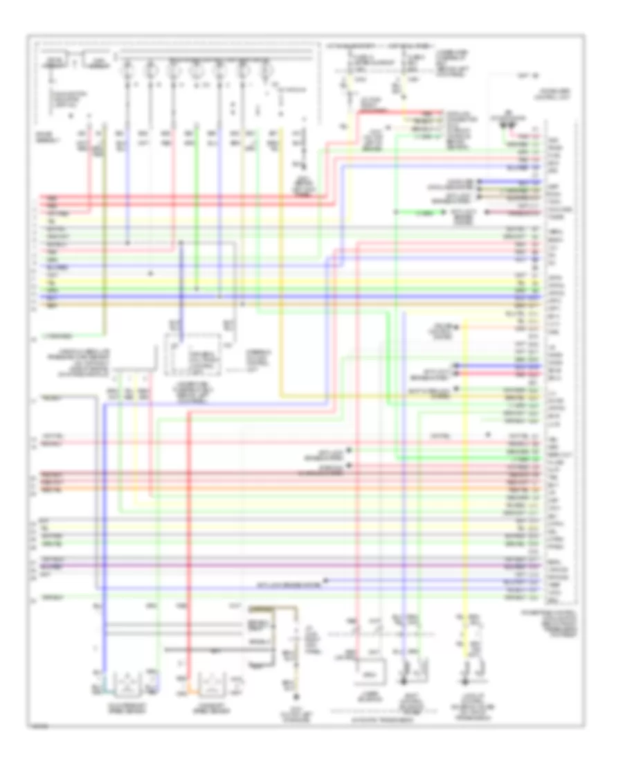
3.5L, Engine Performance Wiring Diagram (3 of 4) for Acura 3.5RL 2004
List of elements for 3.5L, Engine Performance Wiring Diagram (3 of 4) for Acura 3.5RL 2004:
- (left rear of engine compt) left primary heated oxygen sensor (left primary ho2s)
- (on lower right front of engine) vehicle speed sensor (vss)
- (on right exhaust manifold) right primary heated oxygen sensor (right primary ho2s)
- (on underside of vehicle, left side of transmission) a/t gear position switch
- (right kick panel) j/c c448
- Air conditioning system
- Anti-lock brakes system
- Brake pedal position switch (behind dash, top of brake pedal support)
- C301
- C307
- Engine coolant temperature (ect) sensor (on top left front of engine, on left side of water passage)
- Exhaust gas recirculation (egr) valve position sensor (on top right rear of engine)
- Fuel tank pressure sensor (under left rear of vehicle)
- Fuse 39 stop horn 20a
- Fuse 55 meter 15a
- Fuse 56 back up radio 7.5a
- G101 (at top left of engine)
- G402 (behind right kick panel)
- Gauge relay
- Hot at all times
- Intake air temperature (iat) sensor (on center rear of engine, in intake manifold)
- J/c c114 (at right front of engine)
- J/c c448 (right kick panel)
- J/c c456 (below right side of dash)
- J/c c464 (below right side of dash)
- Left knock sensor
- Mirrors system
- P r
- Power steering pressure (psp) switch (on lower right front of engine compt, on power steering line)
- Red
- Right knock sensor
- Service check connector (below right side of dash, under glove box)
- Throttle position (tp) sensor (on top of engine, on throttle body)
- Under-hood fuse/relay box (on left side of engine compt)
- Underhood relay box "c" (on left front of engine compt)
3.5L, Engine Performance Wiring Diagram (4 of 4) for Acura 3.5RL 2004
List of elements for 3.5L, Engine Performance Wiring Diagram (4 of 4) for Acura 3.5RL 2004:
- A/t & cruise control lights-on circuit
- A10
- A22
- Acs
- Air conditioning system
- Altf
- Anti-lock brakes system
- Atp 1
- Atp 2
- Atp d3
- Atp d4
- Atp pn
- Atp r
- Automatic transmission
- B23
- B24
- B25
- B26
- B27
- B28
- B29
- B30
- Baro out
- Bksw
- C2 pnk
- C404
- C5 red
- C501
- Computer data lines system
- Countershaft speed sensor
- Crs
- Cruise control system
- Cyp1m
- Cyp2m
- D16
- D4 ind
- Data link connector (dlc) (in front console, behind ashtray)
- Drive circuit
- Driver's multiplex control unit
- E15
- E21
- Ect
- Egrl
- Flr2
- Fuse 13 meter sunroof 7.5a
- Fuse 6 ecu 20a
- G101 (on top left of engine)
- G401 (behind left kick panel)
- Gauge assembly
- Hot at all times
- Hot in on or start
- Iat
- Ilu
- Immobilizer control unit
- Imo code
- J/c c448 (right kick panel)
- J/c c448 right kick panel)
- K-line
- Ksl
- Ksr
- Lc a
- Lc b
- Linear solenoid
- Lock-up control solenoid valves (on top of transmission)
- Lpho2s
- Ls +
- Ls-
- Main circuit
- Mainshaft speed sensor
- Malfunction indicator lamp (mil)
- Manifold absolute pressure (map) sensor (on top right side of engine, on intake manifold)
- Map
- Ncsg
- Nep
- Nmsg
- Pdsw
- Pnk e20
- Powertrain control module (pcm) (below front passenger's footrest)
- Ptank
- Red
- Red (or pnk)
- Rpho2s
- Scs
- Sdla
- Sdlb
- Sg1
- Sg2
- Sh a
- Sh b
- Shift control solenoid valves
- Shift interlock system
- Starting/ charging system
- Steering column control unit
- Sts
- Tcfc
- Tcinh
- Tcstb
- Tps
- Under-dash fuse/relay box (behind left kick panel)
- Vbsol
- Vbu
- Vcc1
- Vcc2
- Vref