ENGINE PERFORMANCE
1.5L HYBRID
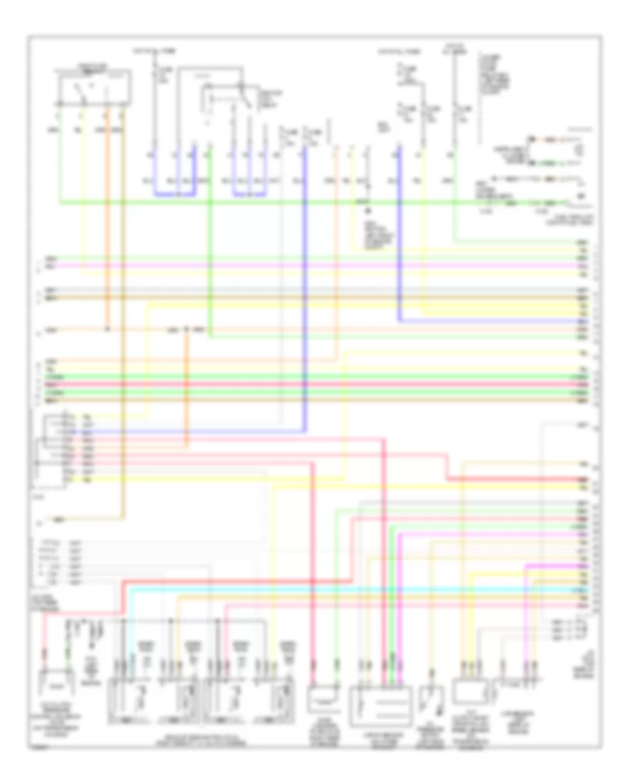
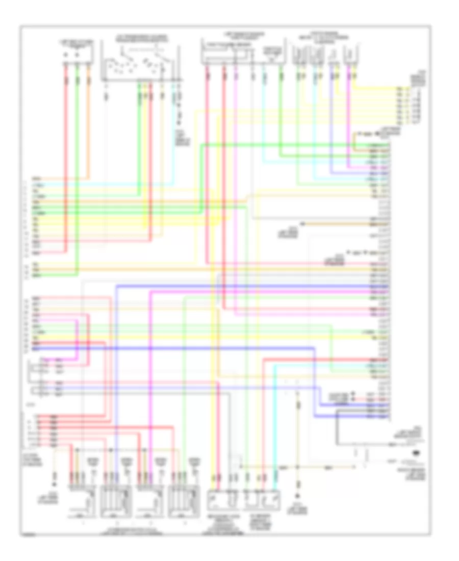
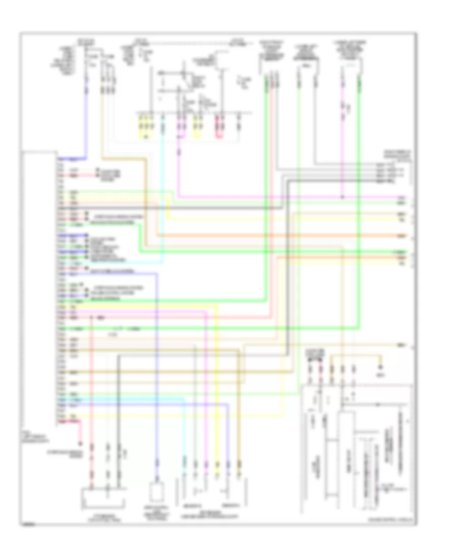
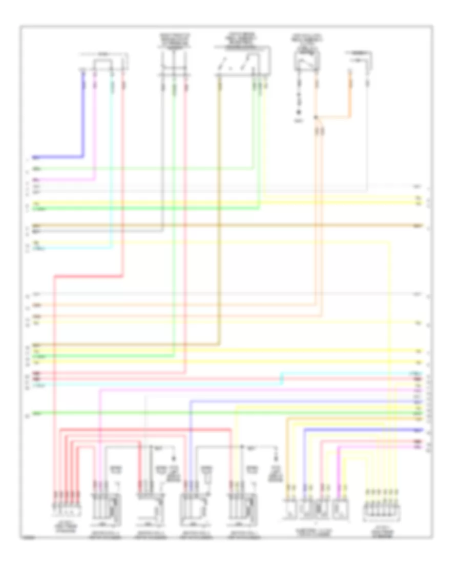
1.5L Hybrid, Engine Controls Wiring Diagram (1 of 6) for Acura ILX 2013

List of elements for 1.5L Hybrid, Engine Controls Wiring Diagram (1 of 6) for Acura ILX 2013:
- (lower left side of radiator) ect sensor 2
- (right front of engine compt) a/c pressure sensor
- (right rear of engine compt) j/c c011
- (under left rear of vehicle) evap canister vent shut valve
- A10
- A11
- A12
- A13
- A14
- A15
- A16
- A17
- A18
- A19
- A20
- A21
- A22
- A23
- A24
- A25
- A26
- A27
- A28
- A29
- A30
- A31
- A32
- A33
- A34
- A35
- A36
- A37
- A38
- A39
- A40
- A41
- A42
- A43
- A44
- A45
- A46
- A47
- A48
- A49
- Air conditioning system
- App sensor (bind center of dash)
- App sensor a
- App sensor b
- Audio navigation unit
- C104
- C123
- Compulsory turning- off circuit
- Computer data lines system
- Cooling fans system
- Eps control unit (behind right kick panel)
- F-can h
- F-can l
- F-can transceiver
- Ftp sensor (top of fuel tank)
- Fuse 15a
- G502 (center of dash)
- Gauge control module
- Hot at all times
- Main circuit
- Malfuction indicator
- Nep
- Pcm (left side of engine compt)
- Pgm-fi sub- relay
- Pnk
- Red
- Starting/ charging system
- Starting/charging system
- Transmissions system
- Under- hood fuse/ relay box (left rear of engine compt)
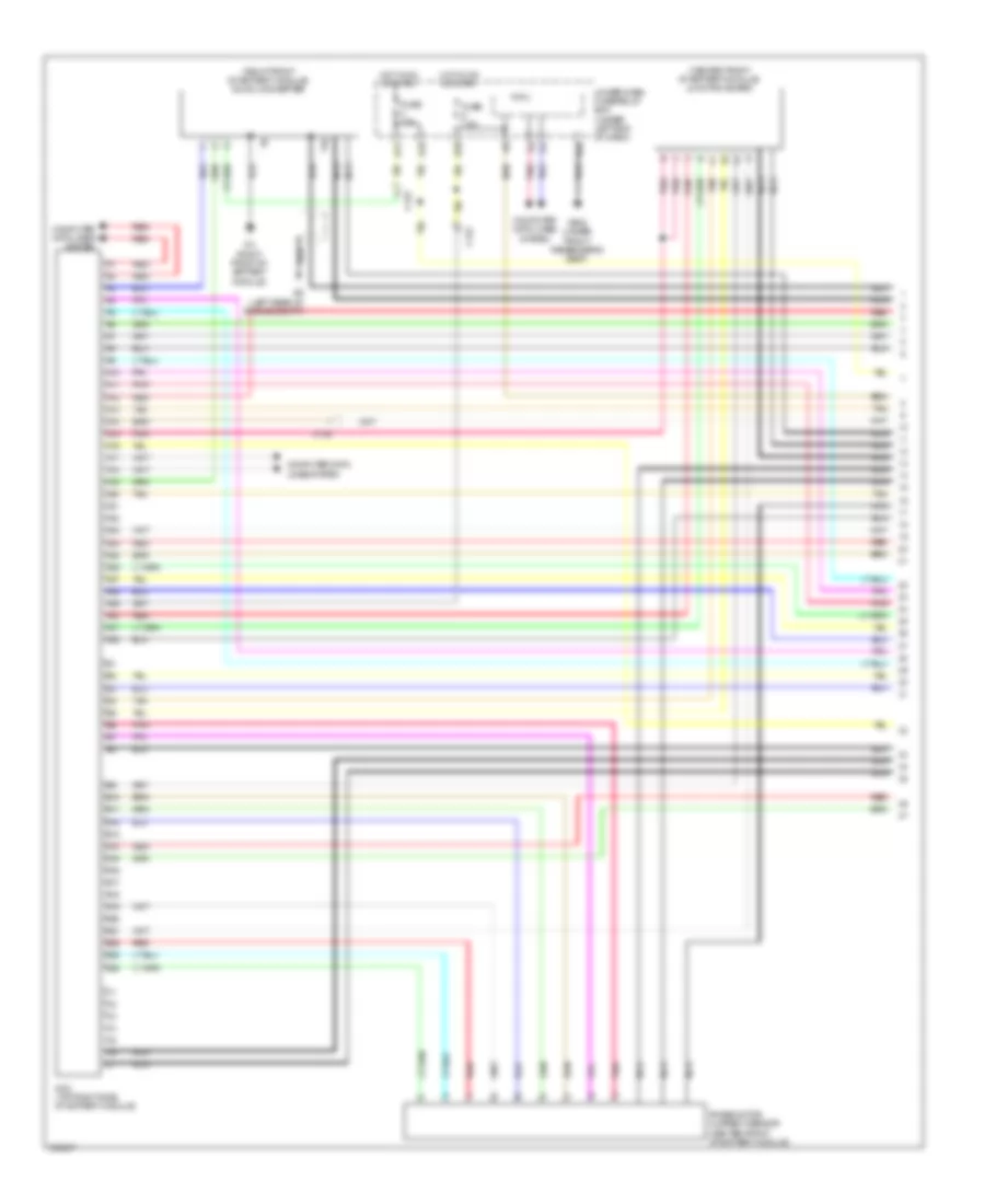
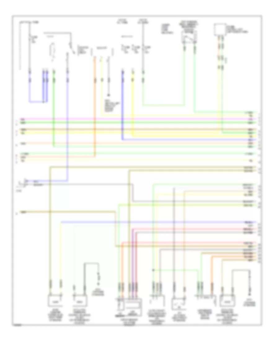
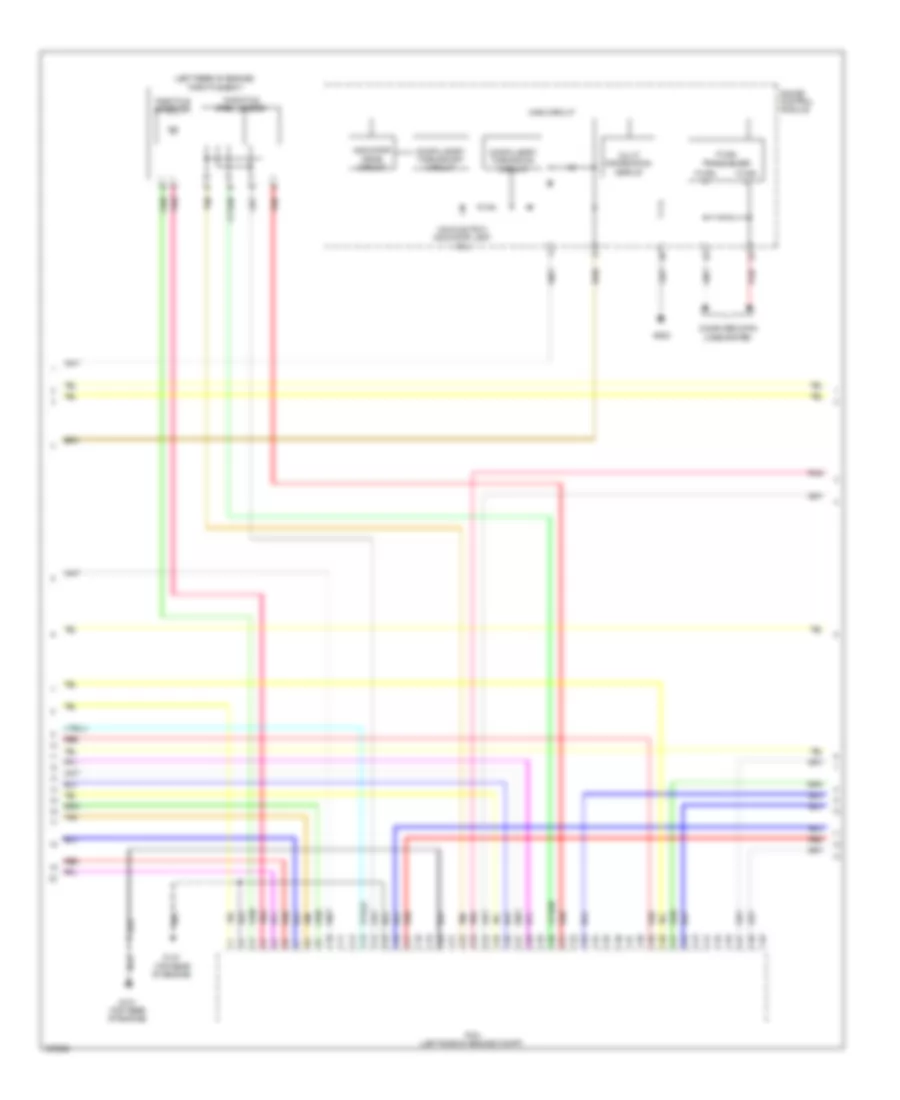
1.5L Hybrid, Engine Controls Wiring Diagram (2 of 6) for Acura ILX 2013
List of elements for 1.5L Hybrid, Engine Controls Wiring Diagram (2 of 6) for Acura ILX 2013:
- (under
- C123
- C125
- C130
- C131
- Cvt clutch pressure control solenoid valve (on transmission housing)
- Cvt output shaft (drive pulley) speed sensor (on transmission housing)
- Driver's seat)
- Eld unit
- Evap canister puge valve (right rear of engine)
- Exhaust side ignition coils (right side of 1, 2, 3 & 4 cylinders)
- Fuel tank unit (top of fuel tank)
- Fuse 1-6 100a
- Fuse 15a
- Fuse 20a
- G101 (left rear of engine)
- G301 (bottom left front of engine compt)
- G601
- Hot at all times
- Icm
- Ignition coil relay
- Instrument cluster system
- J/c c009 (top rear of engine)
- J/c c010 (top rear of engine)
- Maf/iat sensor (on intake air duct)
- Map sensor (left rear of engine)
- Oil pressure switch (left side of engine)
- Pgm-fi main relay 2
- Pnk
- Red
- Spark plug
- Tan
- Under- hood fuse/ relay box (left rear of engine compt)
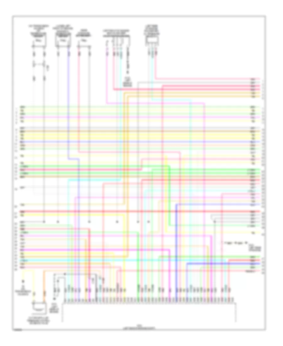
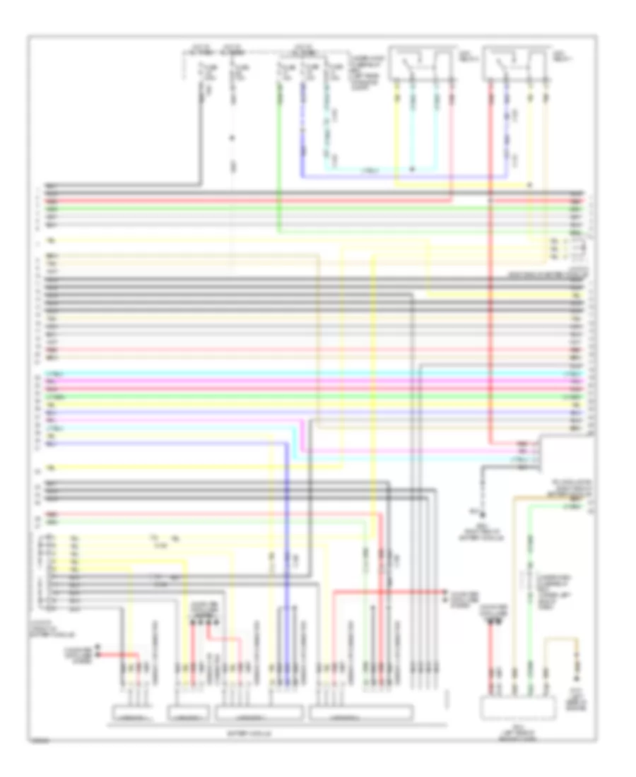
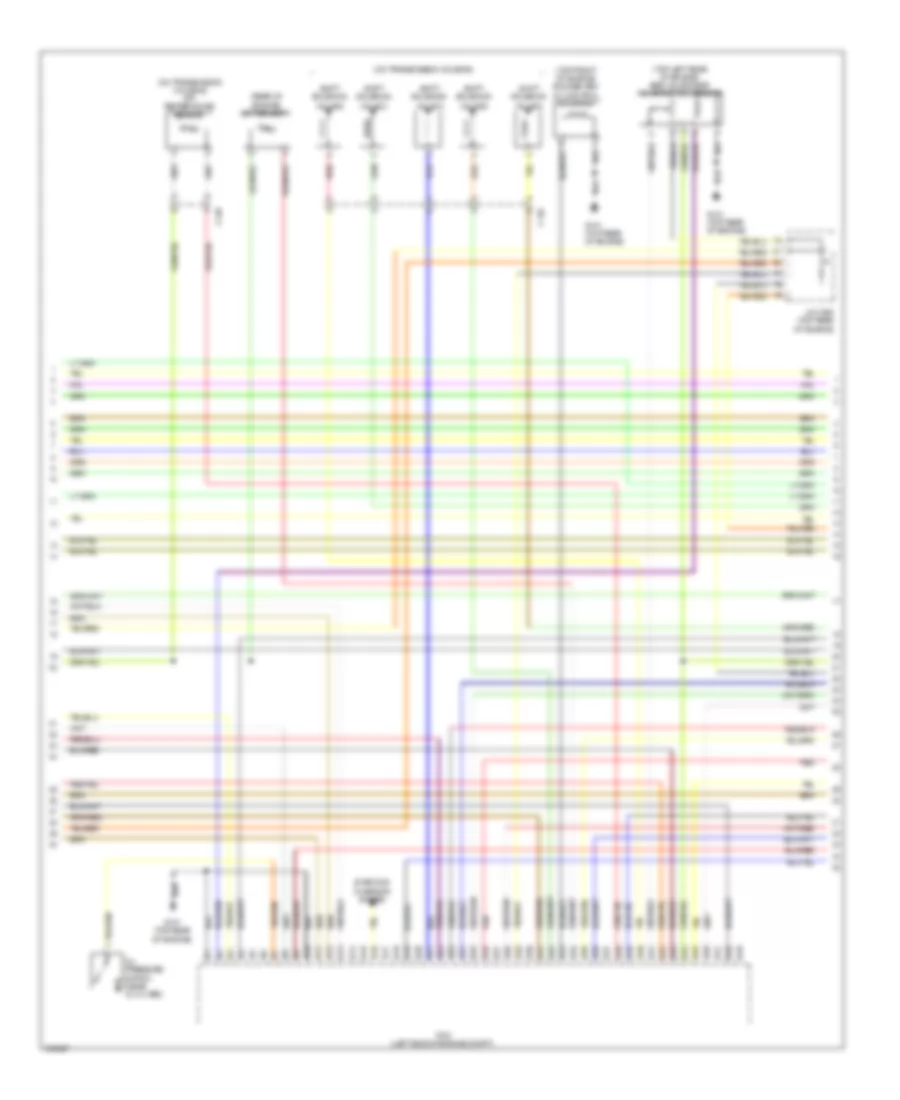
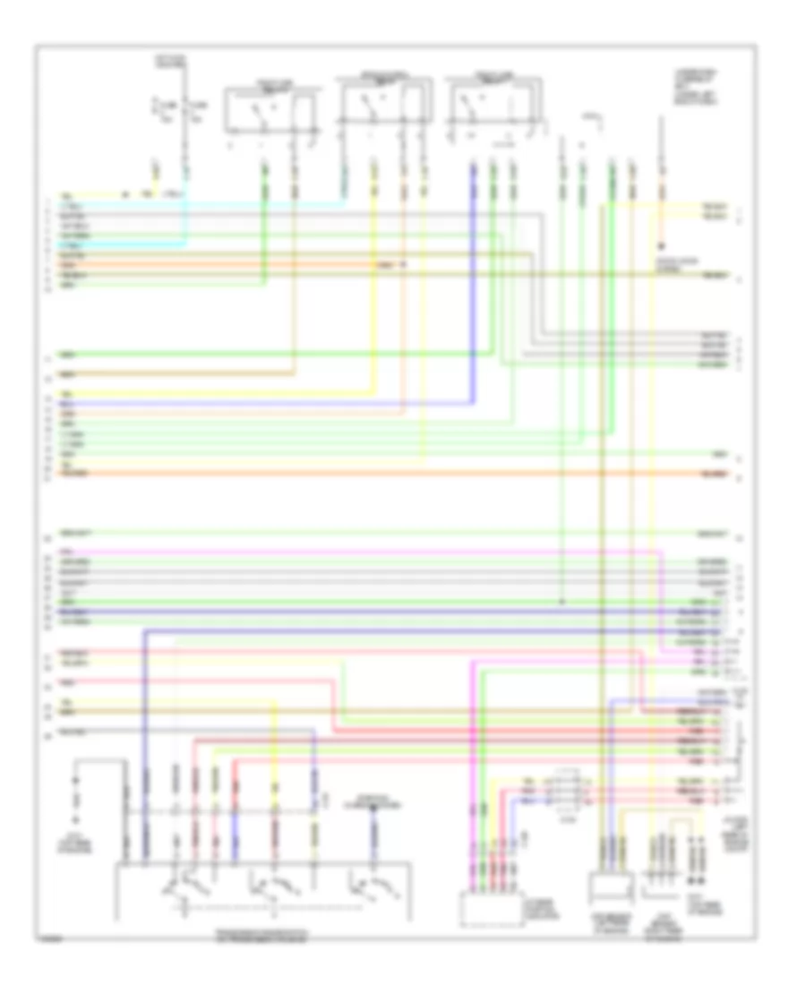
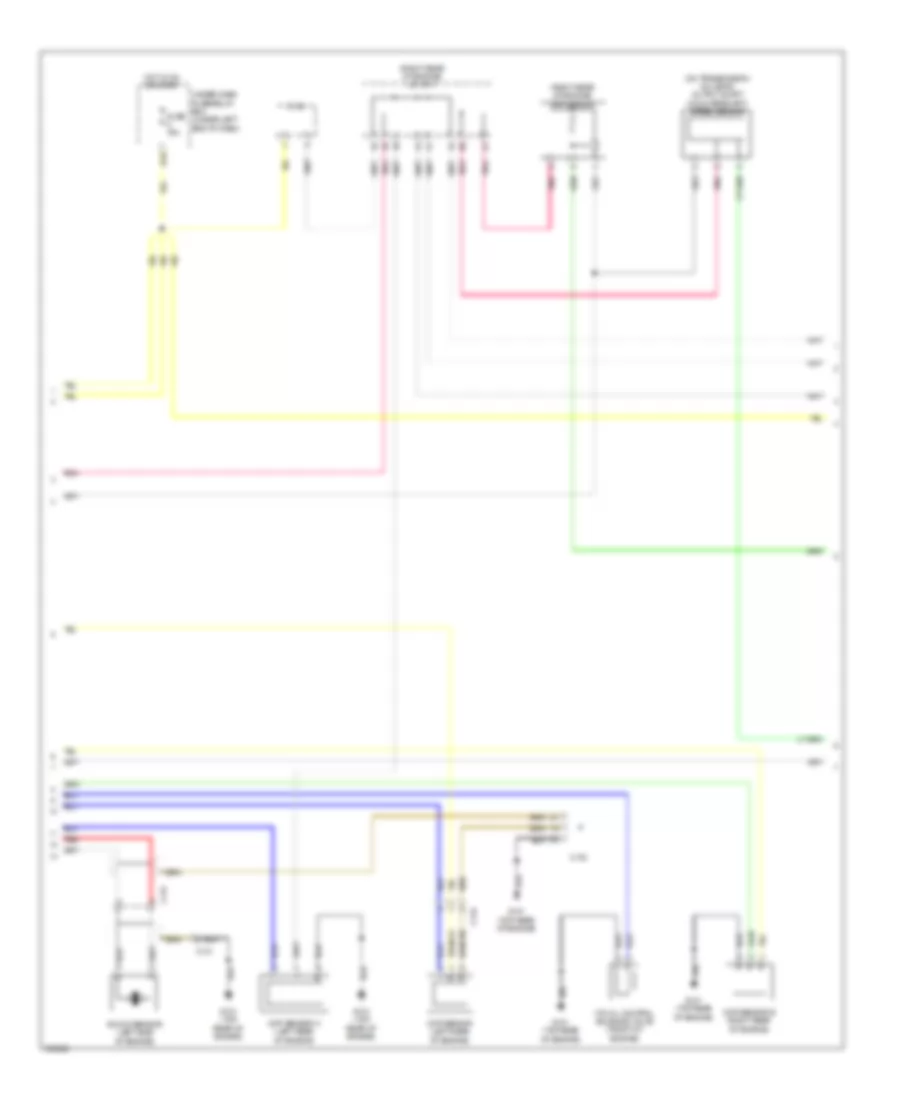
1.5L Hybrid, Engine Controls Wiring Diagram (3 of 6) for Acura ILX 2013
List of elements for 1.5L Hybrid, Engine Controls Wiring Diagram (3 of 6) for Acura ILX 2013:
- (left front of engine) egr valve & egr valve position sensor
- (left rear of engine) rocker arm oil pressure sensor a
- (lower left front of engine) engine oil temperature sensor
- (on transmission housing) atf temperature sensor
- (rear of engine) ect sensor 1
- B10
- B11
- B12
- B13
- B14
- B15
- B16
- B17
- B18
- B19
- B20
- B21
- B22
- B23
- B24
- B25
- B26
- B27
- B28
- B29
- B30
- B31
- B32
- B33
- B34
- B35
- B36
- B37
- B38
- B39
- B40
- B41
- B42
- B43
- B44
- B45
- B46
- B47
- B48
- B49
- C130
- Cvt drive pulley pressure control solenoid valve
- G101 (left rear of engine)
- Pcm (left side of engine compt)
- Pnk
- Red
- T6 (on transmission housing)
- Tan
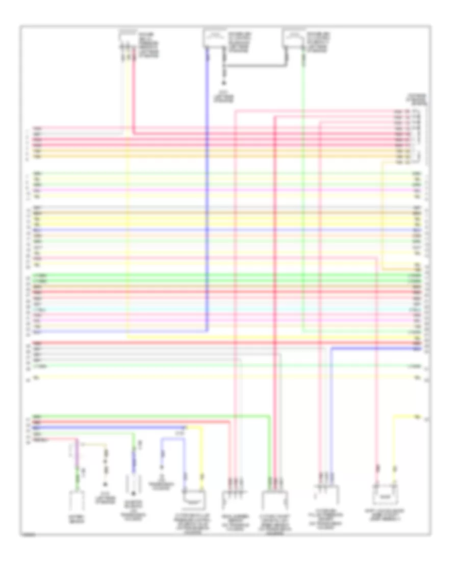
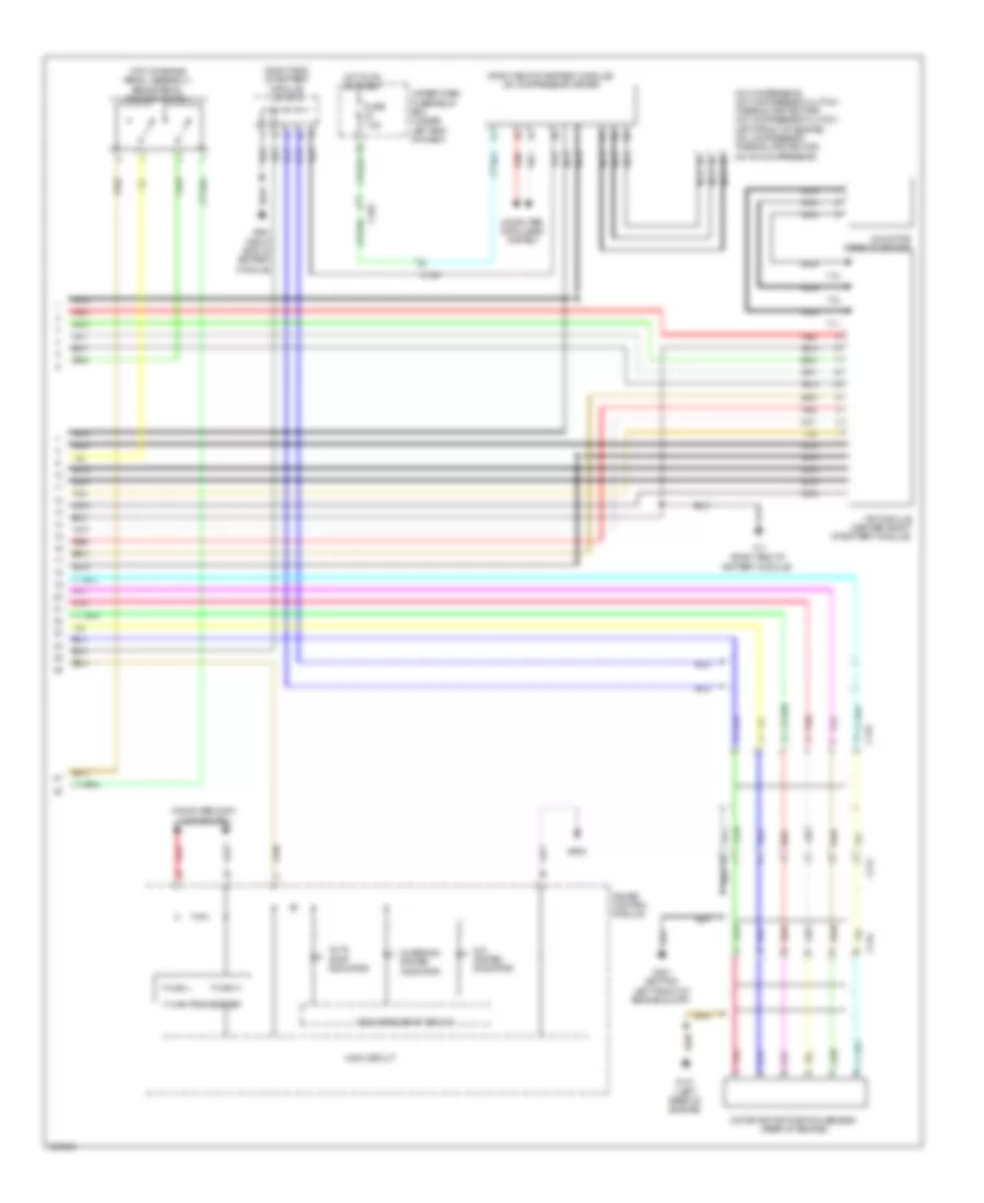
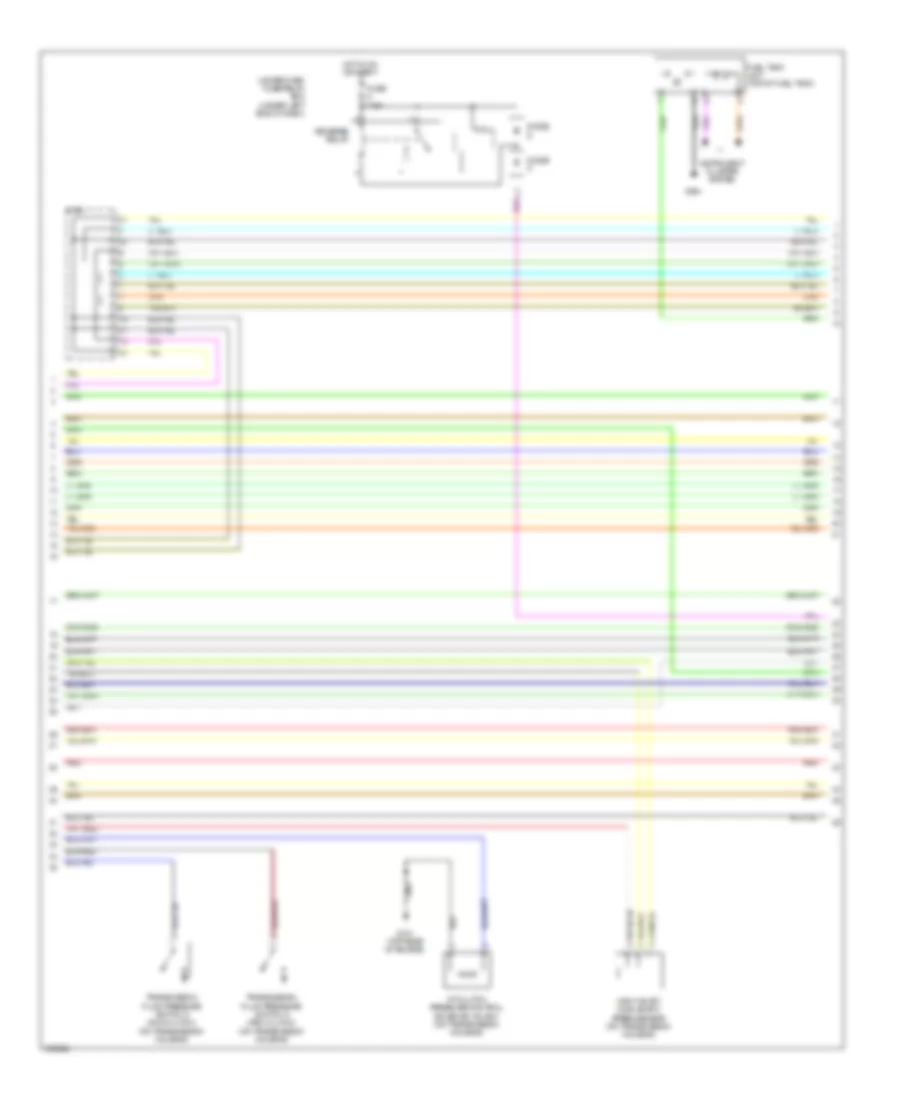
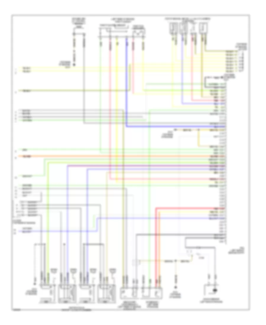
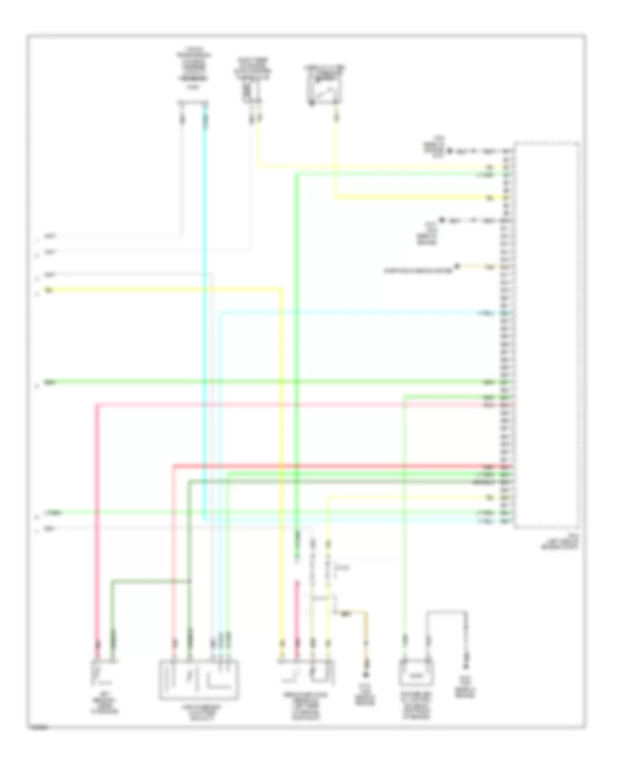
1.5L Hybrid, Engine Controls Wiring Diagram (4 of 6) for Acura ILX 2013
List of elements for 1.5L Hybrid, Engine Controls Wiring Diagram (4 of 6) for Acura ILX 2013:
- (top rear of engine) j/c c010
- Battery sensor
- C130
- C135
- Cvt driven pulley pressure control solenoid valve (on transmission housing)
- Cvt driven pulley pressure sensor (on transmission housing)
- Cvt input shaft (drive pulley) speed sensor (on transmission housing)
- G101 (left rear of engine)
- Inhibitor solenoid (on transmission housing)
- Pnk
- Red
- Rocker arm oil control solenoid a (left rear of engine)
- Rocker arm oil control solenoid b (left rear of engine)
- Rocker arm oil pressure sensor b (left rear of engine)
- Shift lock solenoid (base of shift lever assembly)
- T6 (on transmission housing)
- Tan
- Vehicle speed sensor (on transaxle housing)
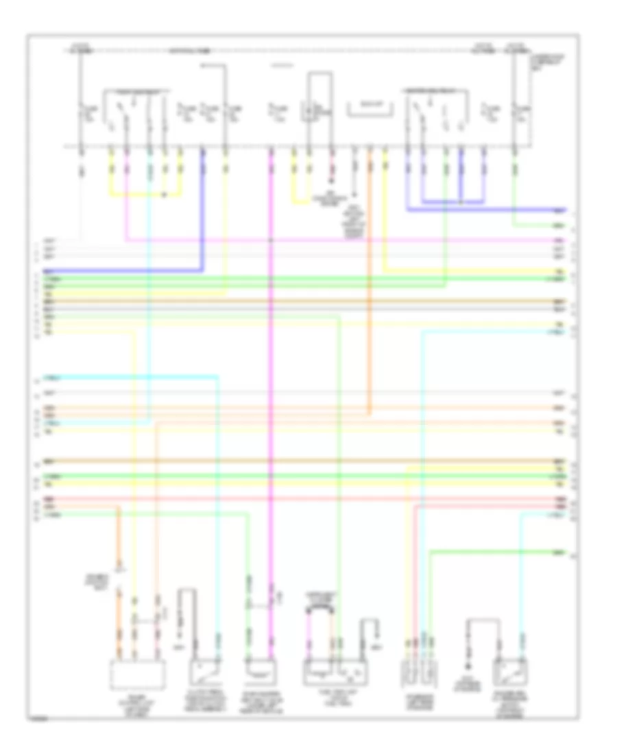
1.5L Hybrid, Engine Controls Wiring Diagram (5 of 6) for Acura ILX 2013
List of elements for 1.5L Hybrid, Engine Controls Wiring Diagram (5 of 6) for Acura ILX 2013:
- A/t gear position indicator
- B26
- B28
- Brake pedal position switch (top of brake pedal assembly)
- C111
- C123
- C13
- C131
- C132
- C16
- C24
- C25
- C30
- C34
- Ckp sensor (left side of engine)
- Cmp sensor (right rear of engine)
- D10
- D12
- D13
- D19
- D23
- Etcs control relay
- Exterior lights system
- Fuse 15a
- Fuse 7.5a
- G101 (left rear of engine)
- G602 (under front passenger's seat)
- Hot in on or start
- Hot w/ accessary relay energized
- Inhibitor relay
- Interior lights system
- Micu
- Pgm-f1 main relay 1
- Pnk
- Power control unit (left side of dash)
- Red
- Starting/ charging system
- Tan
- Under-dash fuse/relay box (under left end of dash)
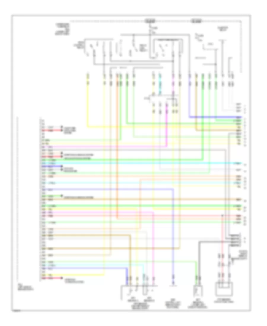
1.5L Hybrid, Engine Controls Wiring Diagram (6 of 6) for Acura ILX 2013
List of elements for 1.5L Hybrid, Engine Controls Wiring Diagram (6 of 6) for Acura ILX 2013:
- (left end of dash) diode e
- (left rear of engine) g101
- (left rear of engine) throttle body
- (on transmission housing) transmission range switch
- (top of engine, above 1, 2, 3 & 4 cylinders) injectors
- (top rear of engine) j/c c010
- A/f sensor (sensor 1) (right rear of engine)
- C10
- C11
- C12
- C13
- C131
- C14
- C15
- C16
- C17
- C18
- C19
- C20
- C21
- C22
- C23
- C24
- C25
- C26
- C27
- C28
- C29
- C30
- C31
- C32
- C33
- C34
- C35
- C36
- C37
- C38
- C39
- C40
- C41
- C42
- C43
- C44
- C45
- C46
- C47
- C48
- C49
- Computer data lines system
- G101 (left rear of engine)
- Icm
- Intake side ignition coils (left side of 1, 2, 3 & 4 cylinders)
- J/c c009 (top rear
- Knock sensor (left side of engine)
- Of engine)
- Pcm (left side of engine compt)
- Pnk
- Red
- Secondary ho2s sensor 2 (in exhaust, downstream of catalytic converter)
- Spark plug
- Tan
- Throttle actuator
- Throttle open sensor
1.5L Hybrid, IMA Wiring Diagram (1 of 3) for Acura ILX 2013
List of elements for 1.5L Hybrid, IMA Wiring Diagram (1 of 3) for Acura ILX 2013:
- (center front of battery module) junction board
- (right front of battery module) dc-dc converter
- A10
- A11
- A12
- A13
- A14
- A15
- A16
- A17
- A18
- A19
- A20
- A21
- A22
- A23
- A24
- A25
- A26
- A27
- A28
- A29
- A30
- A31
- A32
- B10
- B11
- B12
- B13
- B14
- B15
- B16
- B17
- B18
- B19
- B20
- B21
- B22
- B23
- B24
- B28
- B32
- C122
- Computer data lines system
- D10
- Fuse 15a
- Fuse 7.5a
- G4 (right front of battery module)
- G5 (left rear of engine compt)
- G602 (under front passenger's seat)
- Hot in on or start
- Mcm (top right side of battery module)
- Micu
- Nca
- Phase motor current sensor (center front of battery module)
- Pnk
- Red
- T10
- Tan
- Under-dash fuse/relay box (under left end of dash)
1.5L Hybrid, IMA Wiring Diagram (2 of 3) for Acura ILX 2013
List of elements for 1.5L Hybrid, IMA Wiring Diagram (2 of 3) for Acura ILX 2013:
- A13
- A25
- Battery module
- C112
- C122
- C123
- C138
- C16
- C20
- C45
- C46
- Computer data lines system
- Connector
- Fuse 1-6 100a
- Fuse 10a
- Fuse 15a
- Fuse 7.5a
- G101 (left rear of engine)
- G901 (right end of battery module)
- Hot at all times
- Ipu module fan (right end of battery module)
- J/c c013 (right end of battery module)
- J/c c015 (front of battery module)
- Mcm relay 1
- Mcm relay 2
- Nca
- Pcm (left side of engine compt)
- Pnk
- Red
- Sensor 1 5p connector
- Sensor 2 5p
- Sensor 3 4p connector
- Sensor 3 5p connector
- Sensor 4 4p connector
- Sensor 4 5p connector
- T101
- Tan
- Under-dash fuse/relay box (under left end of dash)
- Under-hood fuse/relay box (left rear of engine compt)
- V-sensor 1
- V-sensor 2
- V-sensor 3
- V-sensor 4
1.5L Hybrid, IMA Wiring Diagram (3 of 3) for Acura ILX 2013
List of elements for 1.5L Hybrid, IMA Wiring Diagram (3 of 3) for Acura ILX 2013:
- (right end of battery module) a/c compressor driver
- (right end of battery module) j/c c013
- (top of brake pedal assembly) brake pedal position switch
- A/c compressor (a/c compressor clutch/ thermal protector) (a/c compressor clutch: left front of engine) (a/c compressor thermal protector: on a/c compressor)
- Auto stop indicator
- C102
- C121
- C122
- C134
- Charging system indicator
- Computer data lines system
- F-can h
- F-can l
- F-can transceiver
- Fuse 7.5a
- G101 (left rear of engine)
- G301 (bottom left front of engine compt)
- G502
- G901 (right end of battery module)
- Gauge control module
- Hot in on or start
- Ima motor (rear of engine)
- Ima system indicator
- Indicator drive circuit
- Main circuit
- Motor rotor position sensor (rear of engine)
- Mpi module (center front of battery module)
- Nca
- Pnk
- Red
- T11
- T12
- T13
- T17 (right end of battery module)
- Tan
- Under-dash fuse/relay box (under left end of dash)
2.0L
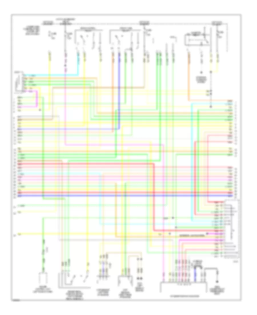
2.0L, Engine Performance Wiring Diagram (1 of 6) for Acura ILX 2013
List of elements for 2.0L, Engine Performance Wiring Diagram (1 of 6) for Acura ILX 2013:
- (lower left side of radiator) ect sensor 2
- (right front of engine compt) a/c pressure sensor
- (right rear of engine compt)
- (under left end of dash)
- (under left rear of vehicle) evap canister vent shut valve
- A/c condenser fan relay
- A/c diode a
- A10
- A11
- A12
- A13
- A14
- A15
- A16
- A17
- A18
- A19
- A20
- A21
- A22
- A23
- A24
- A25
- A26
- A27
- A28
- A29
- A30
- A31
- A32
- A33
- A34
- A35
- A36
- A37
- A38
- A39
- A40
- A41
- A42
- A43
- A44
- A45
- A46
- A47
- A48
- A49
- Air conditioning system
- App sensor (center rear of engine compt)
- C120
- Compulsory turning-off circuit
- Compulsory turning-on circuit
- Computer data lines system
- Cooling fans system computer data lines system
- Cruise control system
- D28
- Display
- Eps control unit (behind right kick panel)
- F-can h
- F-can l
- Ftp sensor (top of fuel tank)
- Fuse 10a
- Fuse 15a
- Fuse 7.5a
- G503
- Gauge control module
- Hot at all times
- Hot in on or start
- Indicator drive circuit
- J/c c010
- Main circuit
- Mil ind
- Multi information
- Pcm (left side of engine compt)
- Pgm-fi sub- relay
- Pnk
- Red
- Sensor a
- Sensor b
- Shift interlock system
- Sound systems
- Starting/charging system
- Transceiver f-can
- Under- dash fuse/ relay box
- Under- hood fuse/ relay box
2.0L, Engine Performance Wiring Diagram (2 of 6) for Acura ILX 2013
List of elements for 2.0L, Engine Performance Wiring Diagram (2 of 6) for Acura ILX 2013:
- (top of brake pedal assembly) brake pedal position switch
- (top rear of engine)
- A/t clutch pressure control solenoid valve a (on transmission housing)
- A/t clutch pressure control solenoid valve b (on transmission housing)
- C111
- C130
- C30
- Eld unit
- Evap canister purge valve (right rear of engine)
- Fuse 15a
- G101
- G101 (top rear of engine)
- G301 (bottom left front of engine compt)
- Hot at all times
- Iat sensor
- Ignition coil relay
- Imt actuator (right front of engine)
- Maf sensor
- Maf/iat sensor (on intake air duct)
- Map sensor (right rear side of engine)
- Output shaft (counter shaft) speed sensor (on transmission housing)
- Power control unit (left side of dash)
- Under- hood fuse/ relay box
2.0L, Engine Performance Wiring Diagram (3 of 6) for Acura ILX 2013
List of elements for 2.0L, Engine Performance Wiring Diagram (3 of 6) for Acura ILX 2013:
- (on transmission housing)
- (on transmission housing) atf temperature sensor
- (rear of engine) ect sensor 1
- (top front of engine) rocker arm oil control solenoid
- (top left rear of engine) egr valve & egr valve position sensor
- B10
- B11
- B12
- B13
- B14
- B15
- B16
- B17
- B18
- B19
- B20
- B21
- B22
- B23
- B24
- B25
- B26
- B27
- B28
- B29
- B30
- B31
- B32
- B33
- B34
- B35
- B36
- B37
- B38
- B39
- B40
- B41
- B42
- B43
- B44
- B45
- B46
- B47
- B48
- B49
- C126
- G101 (top rear of engine)
- J/c c009 (top rear of engine)
- Oil pressure switch (near oil filter)
- Pcm (left side of engine compt)
- Red
- Shift solenoid
- Starting/ charging system
- Valve a
- Valve b
- Valve c
- Valve d
- Valve e
2.0L, Engine Performance Wiring Diagram (4 of 6) for Acura ILX 2013
List of elements for 2.0L, Engine Performance Wiring Diagram (4 of 6) for Acura ILX 2013:
- A/t clutch pressure control solenoid valve c (on transmission housing)
- C130
- D24
- Diode c
- Diode d
- Fuel tank unit (top of fuel tank)
- Fuse 7.5a
- G101 (top rear of engine)
- G601
- Hot in on or start
- Input shaft (main shaft) speed sensor (on transmission housing)
- Instrument cluster system
- Micu
- Red
- Reverse relay
- Transmission fluid pressure switch a (2nd clutch) (on transmission housing)
- Transmission fluid pressure switch a (3rd clutch) (on transmission housing)
- Under-dash fuse/relay box (under left end of dash)
2.0L, Engine Performance Wiring Diagram (5 of 6) for Acura ILX 2013
List of elements for 2.0L, Engine Performance Wiring Diagram (5 of 6) for Acura ILX 2013:
- A/t gear position indicator
- C120
- C127
- C13
- C130
- C16
- C20
- C25
- C34
- C35
- Ckp sensor (left rear of engine)
- Cmp sensor (right rear of engine)
- D10
- D12
- D19
- D23
- Door locks system
- Etcs control relay
- Fuse 15a
- G101 (top rear of engine)
- Hot in on or start
- J/c c008 (left rear of engine compt)
- Micu
- Pgm-f1 main relay 1
- Pgm-fi main relay 2
- Pnk
- Red
- Starting/ charging system
- Transmission range switch (on transmission housing)
- Under-dash fuse/relay box (under left end of dash)
2.0L, Engine Performance Wiring Diagram (6 of 6) for Acura ILX 2013
List of elements for 2.0L, Engine Performance Wiring Diagram (6 of 6) for Acura ILX 2013:
- (left rear of engine) throttle body
- (top of engine, above 1, 2, 3 & 4 cylinders) injectors
- (top rear of engine) g101
- (top rear of engine) j/c c009
- A/f sensor 1 (left rear of engine)
- C10
- C11
- C12
- C128
- C13
- C14
- C15
- C16
- C17
- C18
- C19
- C20
- C21
- C22
- C23
- C24
- C25
- C26
- C27
- C28
- C29
- C30
- C31
- C32
- C33
- C34
- C35
- C36
- C37
- C38
- C39
- C40
- C41
- C42
- C43
- C44
- C45
- C46
- C47
- C48
- C49
- G101 (top rear of engine)
- Icm
- Ignition coils (top of 1, 2, 3 & 4 cylinders)
- J/c c009 (top rear of engine)
- Knock sensor (left side of engine)
- Pcm (left side of engine compt)
- Red
- Rocker arm oil control switch
- Secondary ho2s sensor 2 (left rear of engine, in exhaust)
- Spark plug
- Throttle actuator
- Throttle open sensor
2.4L
2.4L, Engine Performance Wiring Diagram (1 of 6) for Acura ILX 2013
List of elements for 2.4L, Engine Performance Wiring Diagram (1 of 6) for Acura ILX 2013:
- A10
- A11
- A12
- A13
- A14
- A15
- A16
- A17
- A18
- A19
- A20
- A21
- A22
- A23
- A24
- A25
- A26
- A27
- A28
- A29
- A30
- A31
- A32
- A33
- A34
- A35
- A36
- A37
- A38
- A39
- A40
- A41
- A42
- A43
- A44
- A45
- A46
- A47
- A48
- A49
- Air conditioning system
- App sensor (center rear of engine compt)
- App sensor a
- App sensor b
- C120
- C13
- C133
- C16
- C20
- C24
- C25
- C34
- C35
- Computer data lines system
- Cooling fans system
- D12
- D19
- D28
- Ect sensor 2 (lower left side of radiator)
- Eps control unit (behind right kick panel)
- Etcs control relay
- Ftp sensor (top of fuel tank)
- Fuse 15a
- Fuse 7.5a
- Hot in on or start
- Inhibitor relay
- J/c c012 (right rear of engine compt)
- Micu
- Pcm (left side of engine compt)
- Pgm-fi main relay 1
- Pgm-fi main relay 2
- Pnk
- Red
- Starting/ charging system
- Starting/charging system
- Under-dash fuse/relay box (under left end of dash)
2.4L, Engine Performance Wiring Diagram (2 of 6) for Acura ILX 2013
List of elements for 2.4L, Engine Performance Wiring Diagram (2 of 6) for Acura ILX 2013:
- A/c diode a
- A/f sensor (left rear of engine)
- Air conditioning system
- C111
- C120
- C27
- C34
- Clutch pedal position switch (top of clutch pedal assembly)
- Driver's junction box 1
- Eld unit
- Evap canister vent shut valve (under left rear of vehicle)
- Fuel tank unit (top of fuel tank)
- Fuse 10a
- Fuse 15a
- Fuse 7.5a
- G101 (top rear of engine)
- G301 (bottom left front of engine compt)
- G401
- G601
- Hot at all times
- Ignition coil relay
- Instrument cluster system
- Pgm-fi sub relay
- Pnk
- Power control unit (left side of dash)
- Red
- Rocker arm oil pressure switch (top front of engine)
- Under-hood fuse/relay box
2.4L, Engine Performance Wiring Diagram (3 of 6) for Acura ILX 2013
List of elements for 2.4L, Engine Performance Wiring Diagram (3 of 6) for Acura ILX 2013:
- (right front of engine compt) a/c pressure sensor
- (top of brake pedal assembly) brake pedal position switch
- (top of clutch pedal assembly) clutch interlock switch
- C133
- Diode a
- G102 (left side of engine)
- G401
- Icm
- Ignition coil 1 (top of cylinder)
- Ignition coil 2 (top of cylinder)
- Ignition coil 3 (top of cylinder)
- Ignition coil 4 (top of cylinder)
- Injectors 1, 2, 3 & 4 (top of cylinder)
- J/c c011 (right rear of engine)
- Red
- Spark plug
- Tan
2.4L, Engine Performance Wiring Diagram (4 of 6) for Acura ILX 2013
List of elements for 2.4L, Engine Performance Wiring Diagram (4 of 6) for Acura ILX 2013:
- (left rear of engine) throttle body
- C10
- C11
- C12
- C13
- C14
- C15
- C16
- C17
- C18
- C19
- C20
- C21
- C22
- C23
- C24
- C25
- C26
- C27
- C28
- C29
- C30
- C31
- C32
- C33
- C34
- C35
- C36
- C37
- C38
- C39
- C40
- C41
- C42
- C43
- C44
- C45
- C46
- C47
- C48
- C49
- Compulsory turning-off circuit
- Compulsory turning-on circuit
- Computer data lines system
- F-can h
- F-can l
- F-can transceiver
- G101 (top rear of engine)
- G502
- Gauge control module
- Indicator drive circuit
- Main circuit
- Malfunction indicator lamp (mil)
- Multi information display
- Pcm (left side of engine compt)
- Pnk
- Red
- Tan
- Throttle actuator
- Throttle open sensor
2.4L, Engine Performance Wiring Diagram (5 of 6) for Acura ILX 2013
List of elements for 2.4L, Engine Performance Wiring Diagram (5 of 6) for Acura ILX 2013:
- (on transmission housing) output shaft (countershaft) speed sensor
- (right rear of engine) j/c c011
- (right rear of engine) map sensor
- C131
- C133
- C134
- Ckp sensor (left rear of engine)
- Cmp sensor a (left rear of engine)
- Cmp sensor b (right rear of engine)
- D10
- Fuse 15a
- G101 (top rear of engine)
- Hot in on or start
- Knock sensor (left side of engine)
- Pnk
- Red
- Under-dash fuse/relay box (under left end of dash)
- Vtc oil control solenoid valve (front of engine)
2.4L, Engine Performance Wiring Diagram (6 of 6) for Acura ILX 2013
List of elements for 2.4L, Engine Performance Wiring Diagram (6 of 6) for Acura ILX 2013:
- (near oil filter) oil pressure switch
- (right rear of engine) evap canister purge valve
- (top of transmission housing) reverse lockout solenoid
- (top rear of engine) g101
- B10
- B11
- B12
- B13
- B14
- B15
- B16
- B17
- B18
- B19
- B20
- B21
- B22
- B23
- B24
- B25
- B26
- B27
- B28
- B29
- B30
- B31
- B32
- B33
- B34
- B35
- B36
- B37
- B38
- B39
- B40
- B41
- B42
- B43
- B44
- B45
- B46
- B47
- B48
- B49
- C133
- Ect sensor 1 (rear of engine)
- G101 (top rear of engine)
- Maf/iat sensor (on intake air duct)
- Pcm (left side of engine compt)
- Pnk
- Red
- Rocker arm oil control solenoid (top front of engine)
- Secondary ho2s (sensor 2) (left rear of engine, in exhaust)
- Starting/charging system
- Tan