ENGINE PERFORMANCE
1.8L
1.8L, Wiring Diagram (Integra 1.8L Wiring Diagram 1 Of 2) for Acura Integra GS-R 1997

List of elements for 1.8L, Wiring Diagram (Integra 1.8L Wiring Diagram 1 Of 2) for Acura Integra GS-R 1997:
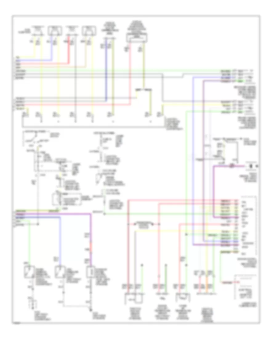
1.8L, Wiring Diagram (Integra 1.8L Wiring Diagram 2 Of 2) for Acura Integra GS-R 1997
List of elements for 1.8L, Wiring Diagram (Integra 1.8L Wiring Diagram 2 Of 2) for Acura Integra GS-R 1997: