ENGINE PERFORMANCE
3.5L
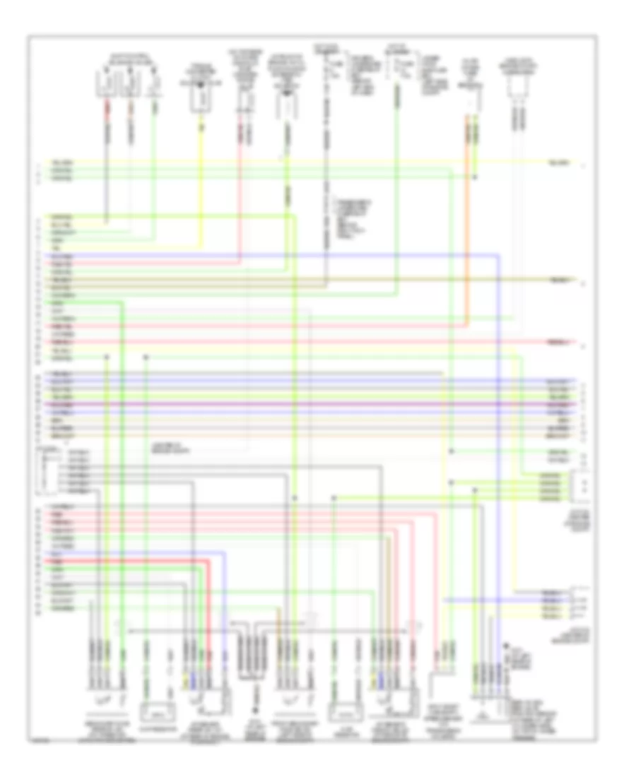
3.5L, Engine Performance Wiring Diagram (1 of 5) for Acura MDX Touring 2004

List of elements for 3.5L, Engine Performance Wiring Diagram (1 of 5) for Acura MDX Touring 2004:
- (at middle of engine compt) map sensor
- (at middle of engine compt) throttle actuator control module
- (at rear of engine, on top of water passage) ect sensor
- (center of engine compt) j/c c104
- (on front of engine) imrc actuator
- (on transaxle end cover) atf temperature sensor
- (on transmission housing) output shaft (countershaft) speed sensor
- A (partial)
- Afshtc b1
- Afshtc b2
- Air conditioning system
- Altc
- Altf
- B22
- Barometer pressure sensor
- Ckp sensor (a & b) (on front of engine)
- Ckpa
- Ckpb
- Climate control unit (lower center of dash, forward of center console)
- Cmp
- Cmp sensor (on right side of engine compt)
- Ect
- Egr
- Egrp
- Fuel injectors
- G101 (at left rear of engine)
- Gnd
- Iat2
- Igls1
- Igls2
- Igls3
- Igls4
- Igls5
- Igls6
- Igp
- Imrc+
- Imrc-
- Imrcm
- Inj1
- Inj2
- Inj3
- Inj4
- Inj5
- Inj6
- Ipb1
- Ipb2
- J/c c103 (center of engine compt)
- Lg1
- Lg2
- Map
- Minh
- Minhi
- Op3sw
- Op4sw
- Pcm (on right side of engine compt)
- Pcs
- Pdsw
- Pnk
- Red
- Rly
- Sedf
- Sefd
- Sg1
- Sg2
- Sha
- Shb
- Shc
- Sho2s b1
- Sho2s b2
- So2shtc b2
- Tatf
- Vbsol
- Vbu
- Vcc1
- Vcc2
- Vcentb1
- Vcentb2
- Vlblb1
- Vlblb2
- Vsb1
- Vsb2
- Vtec oil pressure switch (on lower right front of engine)
- Vtpsw
- Vts
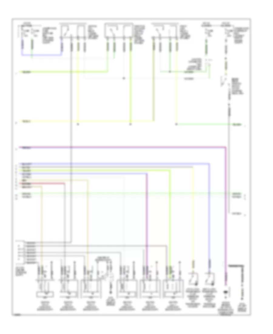
3.5L, Engine Performance Wiring Diagram (2 of 5) for Acura MDX Touring 2004
List of elements for 3.5L, Engine Performance Wiring Diagram (2 of 5) for Acura MDX Touring 2004:
- (at front of engine, on oil pump housing extension) vtec solenoid valve
- (center of engine compt)
- (in air intake tube) iat sensor 2
- (middle of engine compt) alternator
- (on top rear of intake manifold) evap canister purge valve
- A/f sensor (front) (b2, s1) (at middle of engine compt)
- A/f sensor (rear) (b1, s1) (at rear of engine, in exhaust)
- B10
- Braided wire
- Chip resistor
- Driver's underdash fuse/relay box (behind left end of dash)
- Egr valve & egr valve position sensor (at rear of left cylinder head, on top of water passage)
- Front secondary ho2s (b2, s2) (left side of engine compt)
- Fuse 15a
- Fuse 7.5a
- G101 (at left rear of engine)
- H12
- Hot at all times
- Hot in on or start
- Input shaft (mainshaft) speed sensor (on transmission housing)
- J/c c103 (center of engine compt)
- J/c c104
- J/c c104 (center of engine compt)
- J12
- Passenger's underdash fuse/relay box (behind right kick panel)
- Red
- Secondary ho2s (rear b1, s2) (on three way catalytic converter)
- Shift control solenoid valves
- Torque converter clutch solenoid valve
- Under- hood sub-fuse box (left side of engine compt)
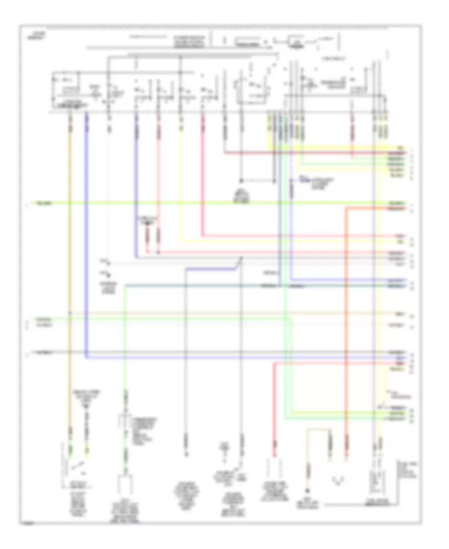
3.5L, Engine Performance Wiring Diagram (3 of 5) for Acura MDX Touring 2004
List of elements for 3.5L, Engine Performance Wiring Diagram (3 of 5) for Acura MDX Touring 2004:
- (center of engine compt)
- 3rd clutch transmission fluid pressure switch (on transaxle end cover)
- 4th clutch transmission fluid pressure switch (on transmission housing)
- A17
- Braided wire
- Brake pedal position switch (at top of brake pedal arm)
- Fuse 15a
- Fuse 20a
- G101 (at left rear of engine)
- Hot at all times
- Icm
- Ignition coil 1 (middle of engine compt)
- Ignition coil 2 (middle of engine compt)
- Ignition coil 3 (middle of engine compt)
- Ignition coil 4 (middle of engine compt)
- Ignition coil 5 (middle of engine compt)
- Ignition coil 6 (middle of engine compt)
- Ignition coil relay (under left side of dash)
- J/c c103 (center of engine compt)
- J/c c104
- Junction connector c404 (under left side of dash)
- Knock sensor (on top of engine block, under intake manifold)
- Pgm-fi main relay 1 (under left side of dash)
- Throttle actuator control module relay (under left side of dash)
- Under-hood fuse sub-fuse box (left side of engine compt)
- Under-hood fuse/relay box (at right side of engine compt)
3.5L, Engine Performance Wiring Diagram (4 of 5) for Acura MDX Touring 2004
List of elements for 3.5L, Engine Performance Wiring Diagram (4 of 5) for Acura MDX Touring 2004:
- (behind upper left end of dash) g401
- (not used)
- 1st hold switch
- 2 position cancel circuit
- A/t gear position/ cruise control dimming circuit
- A/t shift switch (behind center console panel)
- A/t temperature indicator
- A10
- A11
- A12
- A13
- A24
- A27
- A28
- A3 driver's multiplex control unit
- A30
- Back- up lights
- C10
- C12
- C13
- D17
- Driver's power seat control unit (w/ memory) (under
- Driver's seat)
- Driver's underdash fuse/relay box (behind left end of dash)
- Exterior lights system
- Fuel gauge sending unit
- Fuel tank unit (middle of floor)
- G501 (behind left end of dash)
- G601 (below left front seat)
- Gauge assembly
- Immobilizer control unit receiver (in steering column cover)
- Instrument cluster system
- Interlock system
- K10
- Led driver
- Main circuit
- Mil ind
- Passenger's underdash fuse/relay box (behind right kick panel)
- Pnk
- Red
- Regulator
- Vtm-4 control unit (at right side of cargo area, behind rear side trim panel)
- W/o navigation
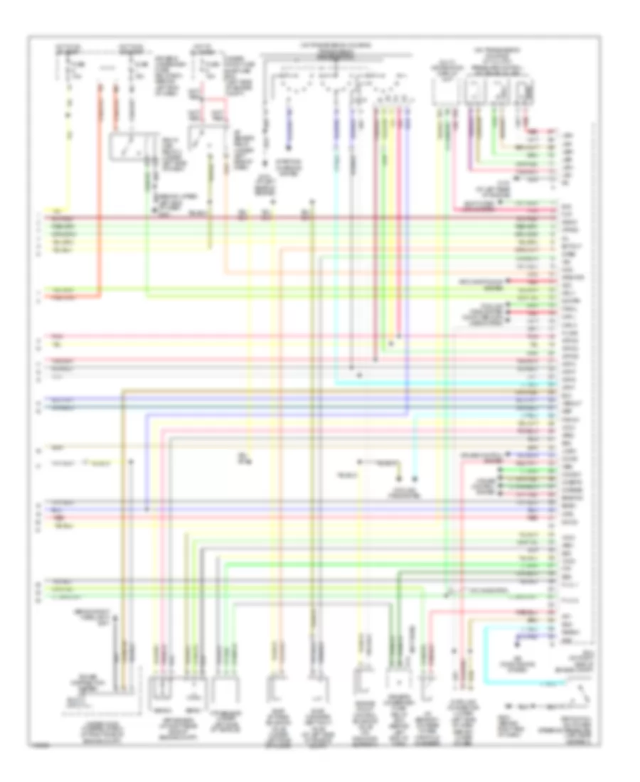
3.5L, Engine Performance Wiring Diagram (5 of 5) for Acura MDX Touring 2004
List of elements for 3.5L, Engine Performance Wiring Diagram (5 of 5) for Acura MDX Touring 2004:
- (behind right headlight) g201
- (not used)
- (on transmission housing) a/t clutch pressure control solenoid valves
- (on transmission housing) transmission range switch
- 2wbs
- A/f sensor relay (under left side of dash)
- Acc
- Acs
- Afshtcr
- Air conditioning system
- App sensor (at right rear side of engine compt)
- Aps1
- Aps2
- Atfind
- Atp d3
- Atp d4
- Atp d5
- Atp f
- Atp n
- Atp p
- Atp r
- Atp2
- B14
- B19
- Bksw
- Bkswnc
- Can h
- Can l
- Ccind
- Ccmsw
- Ccress
- Ccsets
- Cooling fans system
- Cooling fans system computer data lines system
- Cruise control system
- D14
- D5ind
- Data link connector (lower left side of dash, behind lower cover)
- Driver's underdash fuse/ relay box (behind left end of dash)
- Ectout
- Eld
- Eld unit
- Engine mount control solenoid valve (on radiator support)
- Evap by-pass solenoid valve (under left side of floor)
- Evap canister vent shut valve (at left side of engine compt)
- F-lvl 1
- F-lvl 2
- Fan ch
- Fancl
- Ftp
- Ftp sensor (under left side of vehicle)
- Fup
- Fuse 10a
- Fuse 15a
- G101 (at left rear of engine)
- G503 (behind right end of dash)
- Hot at all times
- Hot in on or start
- Iat sensor 1 (on rear intake manifold chamber)
- Iat1
- Imocd
- Imofpr
- K-line
- Left end of dash) g401
- Lhsw
- Lsa+
- Lsa-
- Lsb+
- Lsb-
- Lsc+
- Lsc-
- Mcs
- Mil
- Mrly
- Multi- information display unit
- Nep
- Pcm (on right side of engine compt)
- Pgm-fi main relay 2 (under left side of dash)
- Pnk
- Power distribution system
- Psp switch (on power steering pressure line, near gearbox)
- Pspsw
- Red
- Scs
- Sens 1
- Sens 2
- Sg2
- Sg3
- Sg5
- Shift inter- lock system
- Sls
- Starting/ charging system
- Under- hood fuse sub-fuse box (left side of engine compt)
- Under-hood fuse/relay box (at right side of engine compt)
- Vcc3
- Vcc4
- Vcc5
- Vssout
- Vsv
- W/o navigation
- Wen