ENGINE PERFORMANCE
3.2L
3.2L, Engine Performance Wiring Diagram, A/T (1 of 5) for Acura TL 2007

List of elements for 3.2L, Engine Performance Wiring Diagram, A/T (1 of 5) for Acura TL 2007:
- (left side of dash) j/c c507
- (near brake pedal) brake pedal position switch
- (type s)
- (under middle of dash) j/c c512
- Acc
- Afshtcr
- Air conditioning system
- Anti-theft system
- App sensor (right side of engine compt)
- Apsa
- Apsb
- Atpn
- B10
- B11
- B12
- B13
- B14
- B15
- B16
- B17
- B18
- B19
- B20
- B21
- B22
- B23
- B24
- Bksw
- Bkswnc
- Braided
- Canh
- Canl
- Ckpa
- Ckpb
- Cmp
- Computer data lines system
- Cooling fans system
- E10
- E11
- E12
- E13
- E14
- E15
- E16
- E17
- E18
- E19
- E20
- E21
- E22
- E23
- E24
- E25
- E26
- E27
- E28
- E29
- E30
- E31
- Ect2
- Egr
- Eld
- Etcsrly
- Except type s
- Fanh
- Fanl
- Fpc
- Fpcd
- Ftp
- Fuse 15a
- Fuse 2 15a
- Fuse 20a
- G101 (left side of engine)
- Hot at all times
- Hot in on or start
- Ig1
- Ignition coil relay
- Imocd
- Imofpr
- Imt+
- Imt-
- Imtm
- Ipb1
- Ipb2
- Knock sensor (on top middle of engine, below intake manifold)
- Lg2
- Mcs
- Moonroof control unit (rear of roof)
- Mrly
- Navigation unit (if equipped) (in trunk, below left side of package tray)
- Pcm (behind center of dash)
- Pcs
- Pgm-fi main relay 1
- Pgm-fi main relay 2
- Pnk
- Pspsw
- Red
- Scs
- Sdn
- Sg3
- Sg4
- Shift inter- lock system
- Sho2sb1
- Sho2sb2
- Sls
- Smode
- Sound systems
- Starting/charging system
- Strld
- Strly
- Sts
- Sup
- Throttle actuator control module relay (behind glove box)
- To fuse 23 (diagram 3 of 5)
- Type s
- Under- dash fuse/ relay box (behind left end of dash)
- Under-hood fuse/relay box (left rear of engine compt)
- Vcc3
- Vcc4
- Vcentb1
- Vcentb2
- Vsb1
- Vsb2
- Vsp
- Vssout
- Vsv
- Wen
- X23
- X31
- X32
- X38
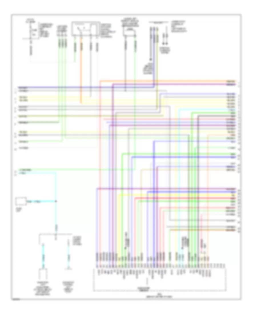
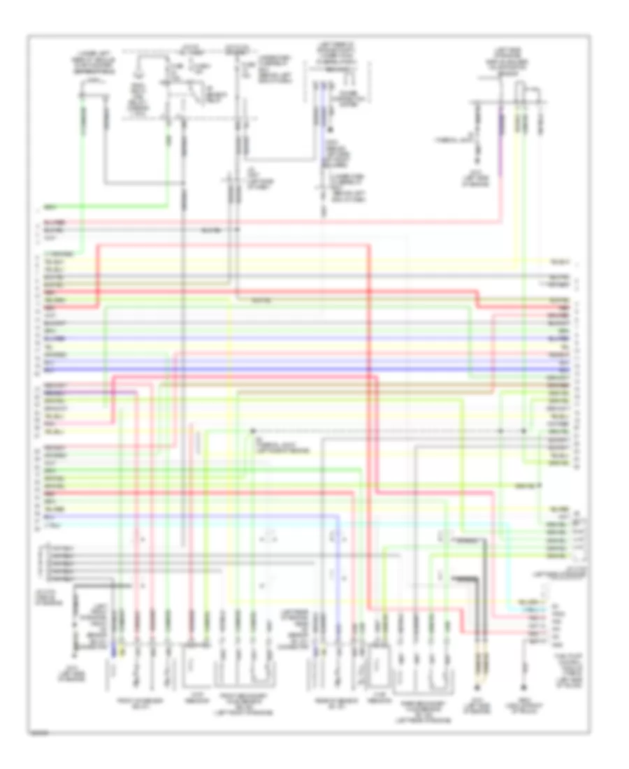
3.2L, Engine Performance Wiring Diagram, A/T (2 of 5) for Acura TL 2007
List of elements for 3.2L, Engine Performance Wiring Diagram, A/T (2 of 5) for Acura TL 2007:
- (at left side of engine compt, near strut tower) evap canister purge valve
- (left rear of engine) engine mount control solenoid valve
- (left side of dash) j/c c508
- (left side of engine)
- (left side of engine) j/c c105
- (middle front of trunk) fuel tank unit
- (right side of engine) psp switch
- (under left rear of vehicle) fuel tank pressure (ftp) sensor
- Atf temperature sensor
- E16
- Ect sensor 2 (under front of engine compt)
- Except type s
- Fuel gauge sending unit
- Fuel pump
- G101 (left side of engine)
- G302 (behind left side of front bumper)
- G503 (under middle of dash)
- G603 (middle front of trunk)
- Imt actuator (right side of engine)
- Instrument cluster system
- J/c c105
- J/c c105 (left side of engine)
- J/c c106 (middle of engine)
- Map sensor (left side of engine)
- Output shaft (countershaft) speed sensor (in transmission housing)
- Pg2
- Pnk
- Red
- Sedf
- Sefd
- Sequential sportshift a/t shift switch
- Sequential sportshift mode switch
- Throttle actuator control module (behind glove box)
- Tp sensor/ throttle actuator (on throttle body)
- Tpsa
- Tpsb
- Transmission gear selection switch/ park pin switch/ a/t gear position indicator panel light (under center console)
- Type s
- Under-dash fuse/relay box (behind left end of dash) x5
- Vcc
3.2L, Engine Performance Wiring Diagram, A/T (3 of 5) for Acura TL 2007
List of elements for 3.2L, Engine Performance Wiring Diagram, A/T (3 of 5) for Acura TL 2007:
- (b1, s1) connector
- (left front of engine) front a/f sensor (b2, s1) connector
- (left rear of engine compt) under-hood fuse/relay box
- (left side of engine) egr valve & egr valve position sensor
- (under left rear of vehicle) evap canister vent shut valve
- A/f sensor relay
- Braided
- Chip resistor
- D13
- Eld unit
- Fp+
- Fp-
- Fpc
- Fpcd
- From pgm fi main relay 1 (diagram 1 of 5)
- Front a/f sensor (b2, s1)
- Front secondary ho2s sensor (b2, s2) (left front of engine)
- Fuel pump control module (type s) (left side of trunk)
- Fuse 15a
- Fuse 4 15a
- Fuse 7.5a
- G101 (left side of engine)
- G302 (behind left side of front bumper)
- G603 (middle front of trunk)
- Gnd
- Hot at all times
- Hot in on or start
- Ig1
- J/c c104 (middle of engine)
- J/c c105 (left side of engine)
- J/c c507 (left side of dash)
- N29
- Pnk
- Power distribution system
- Rear a/f sensor (b1, s1)
- Rear secondary ho2s sensor (b1, s2) (left rear of engine)
- Red
- S1 (thermal joint)
- S3 (thermal joint) (left side of engine)
- Under-dash fuse/relay box (behind left end of dash)
- X10
- X36
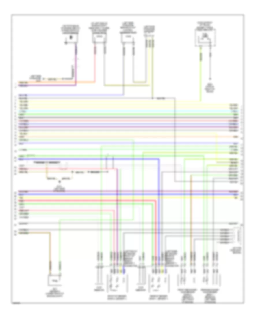
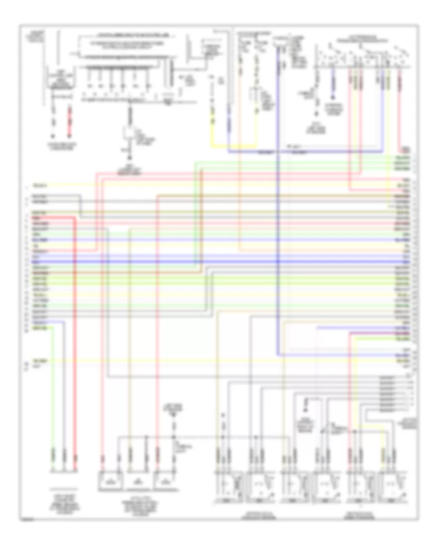
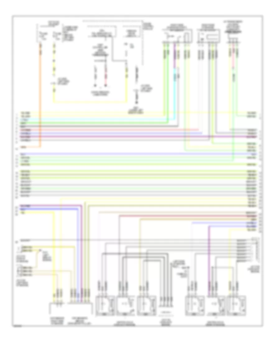
3.2L, Engine Performance Wiring Diagram, A/T (4 of 5) for Acura TL 2007
List of elements for 3.2L, Engine Performance Wiring Diagram, A/T (4 of 5) for Acura TL 2007:
- (left side of engine)
- (left side of engine) g101
- (on transaxle) transmission range switch
- A/t clutch pressure control solenoid valves (on transmission housing)
- A/t gear ind/cruise control dimming circuit
- A/t gear position detection circuit
- A/t gear position ind drive circuit
- A/t gear position indicator brightness control & dimming circuit
- A11
- A13
- A14
- B10
- B18
- Computer data lines system
- Cpu/fail safe circuit/can controller
- Drive circuit
- Fast controller area network transceiver
- Fuse 7.5a
- G101
- G102 (on right front of engine)
- G501 (under left side of dash)
- Gauge control module
- Hot in on or start
- Icm
- Ignition coils (middle of engine)
- Ignition coils (rear of engine)
- Input shaft (mainshaft) speed sensor (in transmission housing)
- J/c c104 (middle of engine)
- J/c c506 (left side of dash)
- J/c c508 (left side of dash)
- Lcd back light
- Micu
- Mil ind
- P16
- P20
- Red
- S1 (thermal joint)
- S2 (thermal joint)
- Shift ind
- Starting/ charging system
- Under- dash fuse/ relay box (behind left end of dash)
- Warning drive circuit
- X20
- X34
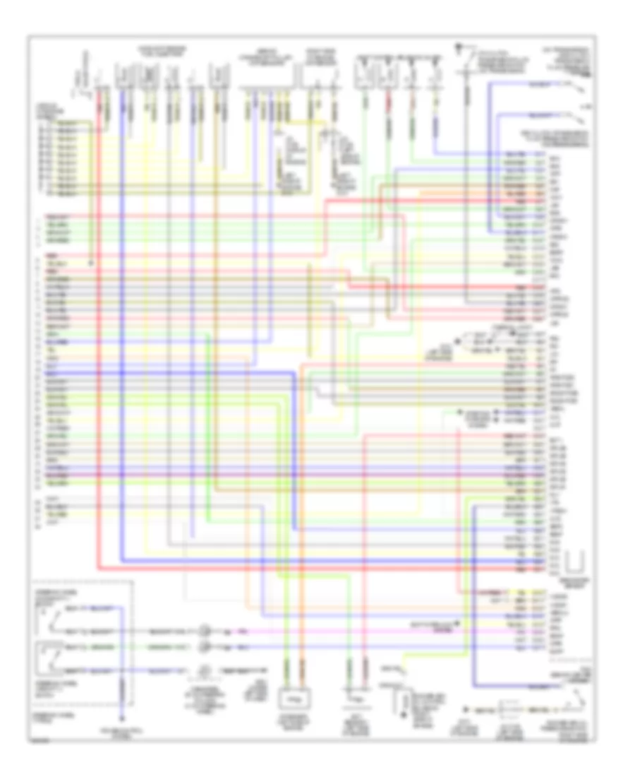
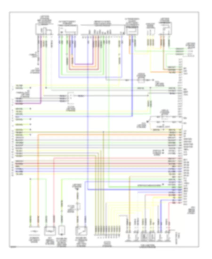
3.2L, Engine Performance Wiring Diagram, A/T (5 of 5) for Acura TL 2007
List of elements for 3.2L, Engine Performance Wiring Diagram, A/T (5 of 5) for Acura TL 2007:
- (behind crankshaft pulley) ckp sensors
- (middle of engine) fuel injectors
- (middle of engine) j/c c104
- (on transmission) 2nd clutch transmission fluid pressure switch
- (right side of engine) cmp sensor
- (thermal joint) s2
- 3rd clutch transmission fluid pressure switch (on transmission)
- 4th clutch transmission fluid pressure switch (on transmission)
- A10
- A11
- A12
- A13
- A14
- A15
- A16
- A17
- A18
- A19
- A20
- A21
- A22
- A23
- A24
- A25
- A26
- A27
- A28
- A29
- A30
- A31
- Afshtcb1
- Afshtcb2
- Altc
- Altf
- Altl
- Atft
- Atpd
- Atpfwd
- Atpl
- Atpp
- Atpr
- Atprvs
- B15
- Barometer sensor
- C10
- C11
- C12
- C13
- C14
- C15
- C16
- C17
- C18
- C19
- C20
- C21
- C22
- Cable reel (b: on steering column) (c: on steering wheel)
- Cruise control system
- D10
- D11
- D12
- D13
- D14
- D15
- D16
- D17
- Ect 1
- Ect sensor 1 (left side of engine)
- Egrp
- Engine) g101
- Except type s
- G101 (left side of engine)
- G501 (under left side of dash)
- Iat
- Iat sensor (left side of engine)
- Igp
- Igpls1
- Igpls2
- Igpls3
- Igpls4
- Igpls5
- Igpls6
- Inj1
- Inj2
- Inj3
- Inj4
- Inj5
- Inj6
- J/c c105 (left side of engine)
- J/c c106 (middle of engine)
- Lg1
- Lsa
- Lsb
- Lsc
- Map
- Op2sw
- Op3sw
- Op4sw
- Pcm (behind center of dash)
- Pg1
- Pg2
- Ppin
- Red
- Rocker arm oil control solenoid (right side of engine)
- Rocker arm oil pressure switch (right side of engine)
- Sdnp
- Sedf
- Sefd
- Sg1
- Sg2
- Sha
- Shb
- Shc
- Shd
- Shift control solenoid valves
- Shift interlock system
- So2shtcb1
- So2shtcb2
- Starting/ charging system
- Steering wheel (type s)
- Steering wheel downshift (-) switch
- Steering wheel upshift (+) switch
- Supp
- Type s
- Vbsol
- Vbsol2
- Vcc1
- Vcc2
- Vlblb1
- Vlblb2
- Vtpsw
- Vts
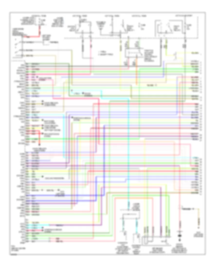
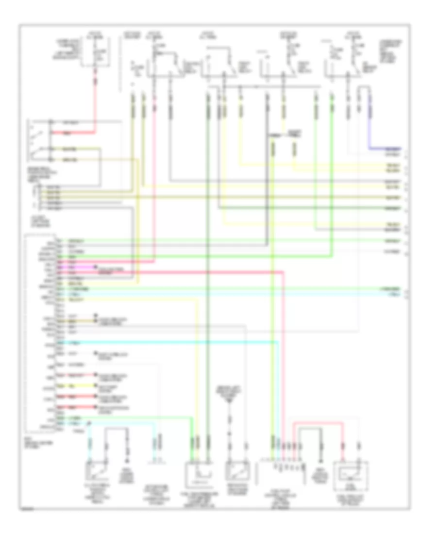
3.2L, Engine Performance Wiring Diagram, M/T (1 of 5) for Acura TL 2007
List of elements for 3.2L, Engine Performance Wiring Diagram, M/T (1 of 5) for Acura TL 2007:
- (behind left side of front bumper) g302
- A/f sensor relay
- Acc
- Active noise control unit (type s) (under middle
- Afshtcr
- Air conditioning system
- Anti-theft system
- Bksw
- Bkswnc
- Brake pedal position switch (near brake pedal)
- Can-h
- Can-l
- Clutch pedal position switch (near clutch pedal)
- Computer data lines system
- Cooling fans system
- Crmcls
- D13
- E10
- E11
- E12
- E13
- E14
- E15
- E16
- E17
- E18
- E19
- E20
- E21
- E22
- E23
- E24
- E25
- E26
- E27
- E28
- E29
- E30
- E31
- Ecm (behind center of dash)
- Eld
- Etcsrly
- Except type s
- Fan-l
- Fp+
- Fp-
- Fpc
- Fpcd
- Ftp
- Fuel pump
- Fuel pump control module (type s) (left side of trunk)
- Fuel tank pressure (ftp) sensor (under left rear of vehicle)
- Fuel tank unit (middle front of trunk)
- Fuse 15a
- Fuse 20a
- Fuse 7.5a
- G503 (under middle of dash)
- G603 (middle front of turnk)
- Gnd
- Hot at all times
- Hot in on or start
- Ig1
- Ignition coil relay
- Imocd
- Imofpr
- J/c c507 (left side of engine)
- Mrly
- N29
- Nep
- Of dash)
- Pgm-fi main relay 1
- Pgm-fi main relay 2
- Pnk
- Psp switch (right side of engine)
- Pspsw
- Red
- Rvs
- Scs
- Sg4
- Shift interlock system
- Type s
- Under-dash fuse/relay box (behind left end of dash)
- Under-hood fuse/relay box (left rear of engine compt)
- Vcc4
- Vssout
- Vsv
- Wen
- X10
- X31
- X32
- X36
- X38
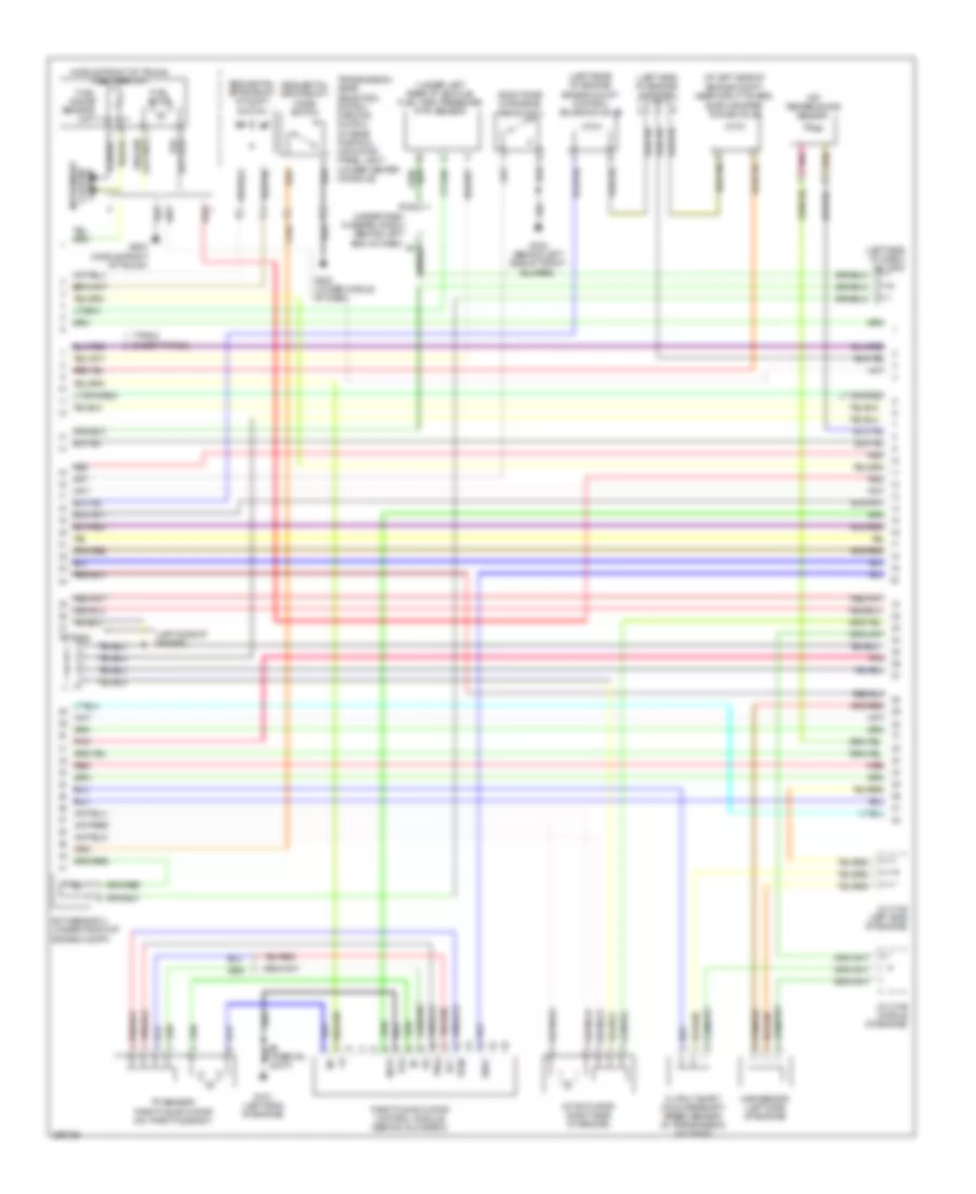
3.2L, Engine Performance Wiring Diagram, M/T (2 of 5) for Acura TL 2007
List of elements for 3.2L, Engine Performance Wiring Diagram, M/T (2 of 5) for Acura TL 2007:
- (left side of dash) j/c c508
- (under left rear of vehicle) evap canister vent shut valve
- Apsa
- Apsb
- Audio unit
- B10
- B11
- B12
- B13
- B14
- B15
- B16
- B17
- B18
- B19
- B20
- B21
- B22
- B23
- B24
- Barometer sensor
- C26
- Ckpa
- Ckpb
- Cmp
- Cooling fans system
- D10
- D11
- D12
- D13
- D14
- D15
- D16
- D17
- Ecm (behind center of dash)
- Ect2
- Egr
- Eld unit
- Fan-h
- Fuse 15a
- G302 (behind left side of front bumper)
- Hot at all times
- Ig1
- Imt+
- Imt-
- Imtm
- Ipb1
- Ipb2
- J/c c512 (under middle of dash)
- Lg2
- Mcs
- Moonroof control unit (rear of roof)
- Navigation unit (if equipped) (in trunk, below left side of package tray)
- Pcs
- Red
- Sg3
- Sho2sb1
- Sho2sb2
- Starting/ charging system
- Sts
- System charging starting/
- Throttle actuator control module relay (behind glove box)
- Under-dash fuse/relay box (behind left end of dash)
- Under-hood fuse/relay box (left rear of engine compt)
- Vbsol2
- Vcc3
- Vcentb1
- Vcentb2
- Vlblb1
- Vlblb2
- Vsb1
- Vsb2
- X23
3.2L, Engine Performance Wiring Diagram, M/T (3 of 5) for Acura TL 2007
List of elements for 3.2L, Engine Performance Wiring Diagram, M/T (3 of 5) for Acura TL 2007:
- (at left side of engine compt, near strut tower) evap canister purge valve
- (left rear of engine) engine mount control solenoid valve
- (left side of engine) g101
- (left side of engine) j/c c105
- (middle front of trunk) (except type s) fuel tank unit
- (on top middle of engine, below intake manifold) knock sensor
- Braided
- Chip resistor
- Ect sensor 2 (under front of engine compt)
- Front a/f sensor (bank 2, sensor 1)
- Front secondary ho2s sensor (bank 2, sensor 2) (left front of engine)
- Fuel pump
- G101 (left side of engine)
- G603 (middle front of trunk)
- J/c c106 (middle of engine)
- Rear a/f sensor (bank 1, sensor 1)
- Rear secondary ho2s sensor (bank 1, sensor 2) (left rear of engine)
- Red
3.2L, Engine Performance Wiring Diagram, M/T (4 of 5) for Acura TL 2007
List of elements for 3.2L, Engine Performance Wiring Diagram, M/T (4 of 5) for Acura TL 2007:
- (in transmission housing) input shaft (mainshaft) speed sensor
- (left side of engine) g101
- (right side of engine compt) app sensor
- (right side of engine) imt actuator
- A13
- A14
- B10
- B18
- Ckp sensors (behind crankshaft pulley)
- Cmp sensor (right side of engine)
- Computer data lines system
- Cpu/ fail safe circuit/ can controller
- Fast controller area network transceiver
- Fuse 7.5a
- G101 (left side of engine)
- G501 (under left side of dash)
- Gauge control module
- Hot in on or start
- Icm
- Ignition coils (middle of engine)
- Ignition coils (rear of engine)
- J/c c104 (middle of engine)
- J/c c105 (left side of engine)
- J/c c106 (middle of engine)
- J/c c506 (left side of dash)
- J/c c508 (left side of dash)
- Mil ind
- Red
- S1 (thermal joint)
- Under-dash fuse/relay box (behind left end of dash)
- Warning drive circuit
- X20
- X34
3.2L, Engine Performance Wiring Diagram, M/T (5 of 5) for Acura TL 2007
List of elements for 3.2L, Engine Performance Wiring Diagram, M/T (5 of 5) for Acura TL 2007:
- (behind glove box) throttle actuator control module
- (in transmission housing) output shaft (countershaft) speed sensor
- (left side of engine) egr valve & egr valve position sensor
- (left side of engine) g101
- (left side of engine) j/c c105
- (left side of engine) map sensor
- (middle of engine) j/c c104
- (on throttle body) tp sensor/ throttle actuator
- A10
- A11
- A12
- A13
- A14
- A15
- A16
- A17
- A18
- A19
- A20
- A21
- A22
- A23
- A24
- A25
- A26
- A27
- A28
- A29
- A30
- A31
- Afshtcb1
- Afshtcb2
- Altc
- Altf
- Altl
- C10
- C11
- C12
- C13
- C14
- C15
- C16
- C17
- C18
- C19
- C20
- C21
- C22
- Ecm (behind center of dash)
- Ect sensor 1 (left side of engine)
- Ect1
- Egrp
- Except type s
- Fuel injectors (middle of engine)
- G101 (left side of engine)
- Gnd
- Iat
- Iat sensor (left side of engine)
- Igp
- Igpls1
- Igpls2
- Igpls3
- Igpls4
- Igpls5
- Igpls6
- Inj1
- Inj2
- Inj3
- Inj4
- Inj5
- Inj6
- J/c c104 (middle of engine)
- J/c c105 (left side of engine)
- Lg1
- Map
- Pg1
- Pg2
- Red
- Rocker arm oil control solenoid (right side of engine)
- Rocker arm oil pressure switch (right side of engine)
- S1 (thermal joint)
- S3 (thermal joint) (left side of engine)
- Sedf
- Sefd
- Sg1
- Sg2
- So2shtcb1
- So2shtcb2
- Starting/ charging system
- Starting/charging system
- Tpsa
- Tpsb
- Type s
- Vbsol
- Vcc
- Vcc1
- Vcc2
- Vtpsw
- Vts
3.5L
3.5L, Engine Performance Wiring Diagram, A/T (1 of 5) for Acura TL 2007
List of elements for 3.5L, Engine Performance Wiring Diagram, A/T (1 of 5) for Acura TL 2007:
- (left side of dash) j/c c507
- (near brake pedal) brake pedal position switch
- (type s)
- (under middle of dash) j/c c512
- Acc
- Afshtcr
- Air conditioning system
- Anti-theft system
- App sensor (right side of engine compt)
- Apsa
- Apsb
- Atpn
- B10
- B11
- B12
- B13
- B14
- B15
- B16
- B17
- B18
- B19
- B20
- B21
- B22
- B23
- B24
- Bksw
- Bkswnc
- Braided
- Canh
- Canl
- Ckpa
- Ckpb
- Cmp
- Computer data lines system
- Cooling fans system
- E10
- E11
- E12
- E13
- E14
- E15
- E16
- E17
- E18
- E19
- E20
- E21
- E22
- E23
- E24
- E25
- E26
- E27
- E28
- E29
- E30
- E31
- Ect2
- Egr
- Eld
- Etcsrly
- Except type s
- Fanh
- Fanl
- Fpc
- Fpcd
- Ftp
- Fuse 15a
- Fuse 2 15a
- Fuse 20a
- G101 (left side of engine)
- Hot at all times
- Hot in on or start
- Ig1
- Ignition coil relay
- Imocd
- Imofpr
- Imt+
- Imt-
- Imtm
- Ipb1
- Ipb2
- Knock sensor (on top middle of engine, below intake manifold)
- Lg2
- Mcs
- Moonroof control unit (rear of roof)
- Mrly
- Navigation unit (if equipped) (in trunk, below left side of package tray)
- Pcm (behind center of dash)
- Pcs
- Pgm-fi main relay 1
- Pgm-fi main relay 2
- Pnk
- Pspsw
- Red
- Scs
- Sdn
- Sg3
- Sg4
- Shift inter- lock system
- Sho2sb1
- Sho2sb2
- Sls
- Smode
- Sound systems
- Starting/charging system
- Strld
- Strly
- Sts
- Sup
- Throttle actuator control module relay (behind glove box)
- To fuse 23 (diagram 3 of 5)
- Type s
- Under- dash fuse/ relay box (behind left end of dash)
- Under-hood fuse/relay box (left rear of engine compt)
- Vcc3
- Vcc4
- Vcentb1
- Vcentb2
- Vsb1
- Vsb2
- Vsp
- Vssout
- Vsv
- Wen
- X23
- X31
- X32
- X38
3.5L, Engine Performance Wiring Diagram, A/T (2 of 5) for Acura TL 2007
List of elements for 3.5L, Engine Performance Wiring Diagram, A/T (2 of 5) for Acura TL 2007:
- (at left side of engine compt, near strut tower) evap canister purge valve
- (left rear of engine) engine mount control solenoid valve
- (left side of dash) j/c c508
- (left side of engine)
- (left side of engine) j/c c105
- (middle front of trunk) fuel tank unit
- (right side of engine) psp switch
- (under left rear of vehicle) fuel tank pressure (ftp) sensor
- Atf temperature sensor
- E16
- Ect sensor 2 (under front of engine compt)
- Except type s
- Fuel gauge sending unit
- Fuel pump
- G101 (left side of engine)
- G302 (behind left side of front bumper)
- G503 (under middle of dash)
- G603 (middle front of trunk)
- Imt actuator (right side of engine)
- Instrument cluster system
- J/c c105
- J/c c105 (left side of engine)
- J/c c106 (middle of engine)
- Map sensor (left side of engine)
- Output shaft (countershaft) speed sensor (in transmission housing)
- Pg2
- Pnk
- Red
- Sedf
- Sefd
- Sequential sportshift a/t shift switch
- Sequential sportshift mode switch
- Throttle actuator control module (behind glove box)
- Tp sensor/ throttle actuator (on throttle body)
- Tpsa
- Tpsb
- Transmission gear selection switch/ park pin switch/ a/t gear position indicator panel light (under center console)
- Type s
- Under-dash fuse/relay box (behind left end of dash) x5
- Vcc
3.5L, Engine Performance Wiring Diagram, A/T (3 of 5) for Acura TL 2007
List of elements for 3.5L, Engine Performance Wiring Diagram, A/T (3 of 5) for Acura TL 2007:
- (b1, s1) connector
- (left front of engine) front a/f sensor (b2, s1) connector
- (left rear of engine compt) under-hood fuse/relay box
- (left side of engine) egr valve & egr valve position sensor
- (under left rear of vehicle) evap canister vent shut valve
- A/f sensor relay
- Braided
- Chip resistor
- D13
- Eld unit
- Fp+
- Fp-
- Fpc
- Fpcd
- From pgm fi main relay 1 (diagram 1 of 5)
- Front a/f sensor (b2, s1)
- Front secondary ho2s sensor (b2, s2) (left front of engine)
- Fuel pump control module (type s) (left side of trunk)
- Fuse 15a
- Fuse 4 15a
- Fuse 7.5a
- G101 (left side of engine)
- G302 (behind left side of front bumper)
- G603 (middle front of trunk)
- Gnd
- Hot at all times
- Hot in on or start
- Ig1
- J/c c104 (middle of engine)
- J/c c105 (left side of engine)
- J/c c507 (left side of dash)
- N29
- Pnk
- Power distribution system
- Rear a/f sensor (b1, s1)
- Rear secondary ho2s sensor (b1, s2) (left rear of engine)
- Red
- S1 (thermal joint)
- S3 (thermal joint) (left side of engine)
- Under-dash fuse/relay box (behind left end of dash)
- X10
- X36
3.5L, Engine Performance Wiring Diagram, A/T (4 of 5) for Acura TL 2007
List of elements for 3.5L, Engine Performance Wiring Diagram, A/T (4 of 5) for Acura TL 2007:
- (left side of engine)
- (left side of engine) g101
- (on transaxle) transmission range switch
- A/t clutch pressure control solenoid valves (on transmission housing)
- A/t gear ind/cruise control dimming circuit
- A/t gear position detection circuit
- A/t gear position ind drive circuit
- A/t gear position indicator brightness control & dimming circuit
- A11
- A13
- A14
- B10
- B18
- Computer data lines system
- Cpu/fail safe circuit/can controller
- Drive circuit
- Fast controller area network transceiver
- Fuse 7.5a
- G101
- G102 (on right front of engine)
- G501 (under left side of dash)
- Gauge control module
- Hot in on or start
- Icm
- Ignition coils (middle of engine)
- Ignition coils (rear of engine)
- Input shaft (mainshaft) speed sensor (in transmission housing)
- J/c c104 (middle of engine)
- J/c c506 (left side of dash)
- J/c c508 (left side of dash)
- Lcd back light
- Micu
- Mil ind
- P16
- P20
- Red
- S1 (thermal joint)
- S2 (thermal joint)
- Shift ind
- Starting/ charging system
- Under- dash fuse/ relay box (behind left end of dash)
- Warning drive circuit
- X20
- X34
3.5L, Engine Performance Wiring Diagram, A/T (5 of 5) for Acura TL 2007
List of elements for 3.5L, Engine Performance Wiring Diagram, A/T (5 of 5) for Acura TL 2007:
- (behind crankshaft pulley) ckp sensors
- (middle of engine) fuel injectors
- (middle of engine) j/c c104
- (on transmission) 2nd clutch transmission fluid pressure switch
- (right side of engine) cmp sensor
- (thermal joint) s2
- 3rd clutch transmission fluid pressure switch (on transmission)
- 4th clutch transmission fluid pressure switch (on transmission)
- A10
- A11
- A12
- A13
- A14
- A15
- A16
- A17
- A18
- A19
- A20
- A21
- A22
- A23
- A24
- A25
- A26
- A27
- A28
- A29
- A30
- A31
- Afshtcb1
- Afshtcb2
- Altc
- Altf
- Altl
- Atft
- Atpd
- Atpfwd
- Atpl
- Atpp
- Atpr
- Atprvs
- B15
- Barometer sensor
- C10
- C11
- C12
- C13
- C14
- C15
- C16
- C17
- C18
- C19
- C20
- C21
- C22
- Cable reel (b: on steering column) (c: on steering wheel)
- Cruise control system
- D10
- D11
- D12
- D13
- D14
- D15
- D16
- D17
- Ect 1
- Ect sensor 1 (left side of engine)
- Egrp
- Engine) g101
- Except type s
- G101 (left side of engine)
- G501 (under left side of dash)
- Iat
- Iat sensor (left side of engine)
- Igp
- Igpls1
- Igpls2
- Igpls3
- Igpls4
- Igpls5
- Igpls6
- Inj1
- Inj2
- Inj3
- Inj4
- Inj5
- Inj6
- J/c c105 (left side of engine)
- J/c c106 (middle of engine)
- Lg1
- Lsa
- Lsb
- Lsc
- Map
- Op2sw
- Op3sw
- Op4sw
- Pcm (behind center of dash)
- Pg1
- Pg2
- Ppin
- Red
- Rocker arm oil control solenoid (right side of engine)
- Rocker arm oil pressure switch (right side of engine)
- Sdnp
- Sedf
- Sefd
- Sg1
- Sg2
- Sha
- Shb
- Shc
- Shd
- Shift control solenoid valves
- Shift interlock system
- So2shtcb1
- So2shtcb2
- Starting/ charging system
- Steering wheel (type s)
- Steering wheel downshift (-) switch
- Steering wheel upshift (+) switch
- Supp
- Type s
- Vbsol
- Vbsol2
- Vcc1
- Vcc2
- Vlblb1
- Vlblb2
- Vtpsw
- Vts
3.5L, Engine Performance Wiring Diagram, M/T (1 of 5) for Acura TL 2007
List of elements for 3.5L, Engine Performance Wiring Diagram, M/T (1 of 5) for Acura TL 2007:
- (behind left side of front bumper) g302
- A/f sensor relay
- Acc
- Active noise control unit (type s) (under middle
- Afshtcr
- Air conditioning system
- Anti-theft system
- Bksw
- Bkswnc
- Brake pedal position switch (near brake pedal)
- Can-h
- Can-l
- Clutch pedal position switch (near clutch pedal)
- Computer data lines system
- Cooling fans system
- Crmcls
- D13
- E10
- E11
- E12
- E13
- E14
- E15
- E16
- E17
- E18
- E19
- E20
- E21
- E22
- E23
- E24
- E25
- E26
- E27
- E28
- E29
- E30
- E31
- Ecm (behind center of dash)
- Eld
- Etcsrly
- Except type s
- Fan-l
- Fp+
- Fp-
- Fpc
- Fpcd
- Ftp
- Fuel pump
- Fuel pump control module (type s) (left side of trunk)
- Fuel tank pressure (ftp) sensor (under left rear of vehicle)
- Fuel tank unit (middle front of trunk)
- Fuse 15a
- Fuse 20a
- Fuse 7.5a
- G503 (under middle of dash)
- G603 (middle front of turnk)
- Gnd
- Hot at all times
- Hot in on or start
- Ig1
- Ignition coil relay
- Imocd
- Imofpr
- J/c c507 (left side of engine)
- Mrly
- N29
- Nep
- Of dash)
- Pgm-fi main relay 1
- Pgm-fi main relay 2
- Pnk
- Psp switch (right side of engine)
- Pspsw
- Red
- Rvs
- Scs
- Sg4
- Shift interlock system
- Type s
- Under-dash fuse/relay box (behind left end of dash)
- Under-hood fuse/relay box (left rear of engine compt)
- Vcc4
- Vssout
- Vsv
- Wen
- X10
- X31
- X32
- X36
- X38
3.5L, Engine Performance Wiring Diagram, M/T (2 of 5) for Acura TL 2007
List of elements for 3.5L, Engine Performance Wiring Diagram, M/T (2 of 5) for Acura TL 2007:
- (left side of dash) j/c c508
- (under left rear of vehicle) evap canister vent shut valve
- Apsa
- Apsb
- Audio unit
- B10
- B11
- B12
- B13
- B14
- B15
- B16
- B17
- B18
- B19
- B20
- B21
- B22
- B23
- B24
- Barometer sensor
- C26
- Ckpa
- Ckpb
- Cmp
- Cooling fans system
- D10
- D11
- D12
- D13
- D14
- D15
- D16
- D17
- Ecm (behind center of dash)
- Ect2
- Egr
- Eld unit
- Fan-h
- Fuse 15a
- G302 (behind left side of front bumper)
- Hot at all times
- Ig1
- Imt+
- Imt-
- Imtm
- Ipb1
- Ipb2
- J/c c512 (under middle of dash)
- Lg2
- Mcs
- Moonroof control unit (rear of roof)
- Navigation unit (if equipped) (in trunk, below left side of package tray)
- Pcs
- Red
- Sg3
- Sho2sb1
- Sho2sb2
- Starting/ charging system
- Sts
- System charging starting/
- Throttle actuator control module relay (behind glove box)
- Under-dash fuse/relay box (behind left end of dash)
- Under-hood fuse/relay box (left rear of engine compt)
- Vbsol2
- Vcc3
- Vcentb1
- Vcentb2
- Vlblb1
- Vlblb2
- Vsb1
- Vsb2
- X23
3.5L, Engine Performance Wiring Diagram, M/T (3 of 5) for Acura TL 2007
List of elements for 3.5L, Engine Performance Wiring Diagram, M/T (3 of 5) for Acura TL 2007:
- (at left side of engine compt, near strut tower) evap canister purge valve
- (left rear of engine) engine mount control solenoid valve
- (left side of engine) g101
- (left side of engine) j/c c105
- (middle front of trunk) (except type s) fuel tank unit
- (on top middle of engine, below intake manifold) knock sensor
- Braided
- Chip resistor
- Ect sensor 2 (under front of engine compt)
- Front a/f sensor (bank 2, sensor 1)
- Front secondary ho2s sensor (bank 2, sensor 2) (left front of engine)
- Fuel pump
- G101 (left side of engine)
- G603 (middle front of trunk)
- J/c c106 (middle of engine)
- Rear a/f sensor (bank 1, sensor 1)
- Rear secondary ho2s sensor (bank 1, sensor 2) (left rear of engine)
- Red
3.5L, Engine Performance Wiring Diagram, M/T (4 of 5) for Acura TL 2007
List of elements for 3.5L, Engine Performance Wiring Diagram, M/T (4 of 5) for Acura TL 2007:
- (in transmission housing) input shaft (mainshaft) speed sensor
- (left side of engine) g101
- (right side of engine compt) app sensor
- (right side of engine) imt actuator
- A13
- A14
- B10
- B18
- Ckp sensors (behind crankshaft pulley)
- Cmp sensor (right side of engine)
- Computer data lines system
- Cpu/ fail safe circuit/ can controller
- Fast controller area network transceiver
- Fuse 7.5a
- G101 (left side of engine)
- G501 (under left side of dash)
- Gauge control module
- Hot in on or start
- Icm
- Ignition coils (middle of engine)
- Ignition coils (rear of engine)
- J/c c104 (middle of engine)
- J/c c105 (left side of engine)
- J/c c106 (middle of engine)
- J/c c506 (left side of dash)
- J/c c508 (left side of dash)
- Mil ind
- Red
- S1 (thermal joint)
- Under-dash fuse/relay box (behind left end of dash)
- Warning drive circuit
- X20
- X34
3.5L, Engine Performance Wiring Diagram, M/T (5 of 5) for Acura TL 2007
List of elements for 3.5L, Engine Performance Wiring Diagram, M/T (5 of 5) for Acura TL 2007:
- (behind glove box) throttle actuator control module
- (in transmission housing) output shaft (countershaft) speed sensor
- (left side of engine) egr valve & egr valve position sensor
- (left side of engine) g101
- (left side of engine) j/c c105
- (left side of engine) map sensor
- (middle of engine) j/c c104
- (on throttle body) tp sensor/ throttle actuator
- A10
- A11
- A12
- A13
- A14
- A15
- A16
- A17
- A18
- A19
- A20
- A21
- A22
- A23
- A24
- A25
- A26
- A27
- A28
- A29
- A30
- A31
- Afshtcb1
- Afshtcb2
- Altc
- Altf
- Altl
- C10
- C11
- C12
- C13
- C14
- C15
- C16
- C17
- C18
- C19
- C20
- C21
- C22
- Ecm (behind center of dash)
- Ect sensor 1 (left side of engine)
- Ect1
- Egrp
- Except type s
- Fuel injectors (middle of engine)
- G101 (left side of engine)
- Gnd
- Iat
- Iat sensor (left side of engine)
- Igp
- Igpls1
- Igpls2
- Igpls3
- Igpls4
- Igpls5
- Igpls6
- Inj1
- Inj2
- Inj3
- Inj4
- Inj5
- Inj6
- J/c c104 (middle of engine)
- J/c c105 (left side of engine)
- Lg1
- Map
- Pg1
- Pg2
- Red
- Rocker arm oil control solenoid (right side of engine)
- Rocker arm oil pressure switch (right side of engine)
- S1 (thermal joint)
- S3 (thermal joint) (left side of engine)
- Sedf
- Sefd
- Sg1
- Sg2
- So2shtcb1
- So2shtcb2
- Starting/ charging system
- Starting/charging system
- Tpsa
- Tpsb
- Type s
- Vbsol
- Vcc
- Vcc1
- Vcc2
- Vtpsw
- Vts