ENGINE PERFORMANCE
1.8L
1.8L, Engine Performance Wiring Diagram (1 of 3) for Audi A4 Quattro 2001

List of elements for 1.8L, Engine Performance Wiring Diagram (1 of 3) for Audi A4 Quattro 2001:
- (m/t)
- (pins 10-17 not used)
- (pins 23-24 not used)
- 13-way relay carrier
- A/c system
- Abs system, transmissions system, instrument cluster system
- Acc
- Brake booster pressure sensor (a/t only)
- Brake booster relay (in 13-way relay carrier)
- Brake booster vacuum pump (a/t only)
- Brake light switch (above brake pedal, on bracket)
- Clutch vacuum vent valve switch (above clutch, on bracket)
- Cruise control system
- Fuse 10a
- Fuse 15a
- Fuse panel
- G104 (left side of engine compt)
- Heated oxygen sensor 1 (right side of eng, on exhaust manifold)
- Heated oxygen sensor 2 (behind 3-way catalytic converter)
- Hot at all times
- Hot in start or run
- Ignition switch
- Mass airflow (maf) sensor (inside air cleaner housing)
- Motronic engine control module (near brake booster, in protective case)
- Nca
- Off
- Red
- Run
- Start
- Throttle position (tp) sensor (on throttle body)
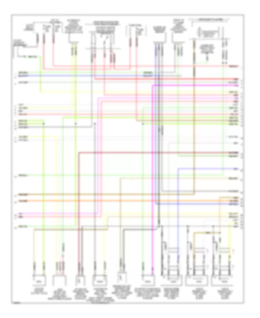
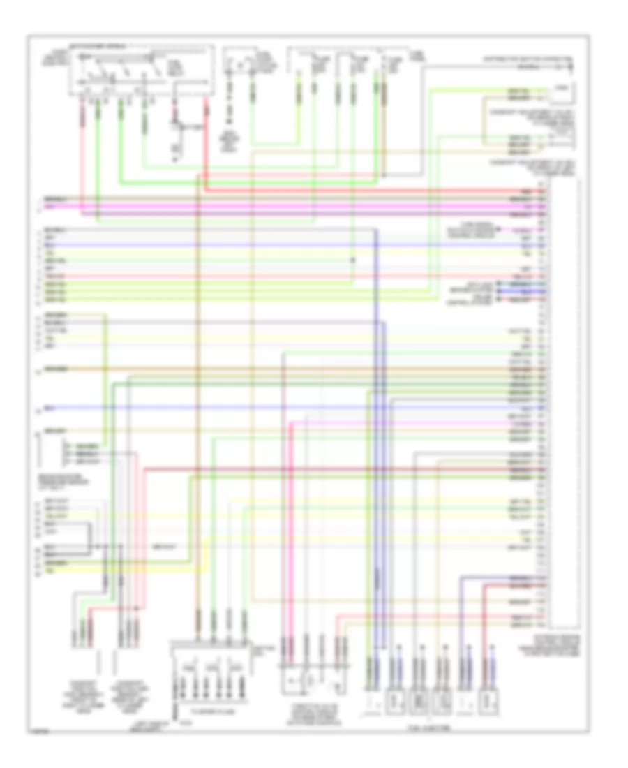
1.8L, Engine Performance Wiring Diagram (2 of 3) for Audi A4 Quattro 2001
List of elements for 1.8L, Engine Performance Wiring Diagram (2 of 3) for Audi A4 Quattro 2001:
- (front of cylinder head) camshaft position (cmp) sensor
- (mil)
- (near brake booster) 3-way relay carrier
- (on rear of intake manifold) secondary air injection (air) solenoid valve
- (under left side of dash) data link connector
- 3-way relay carrier
- Charge air pressure sensor
- Engine coolant temperature (ect) sensor (rear of cylinder, on coolant flange)
- Engine speed (rpm) sensor (left side of eng, near oil filter)
- Evaporative emission (evap) canister purge regulator valve (top of air cleaner housing)
- Fuse 15a
- Fuse 20a
- Fuse 40a
- Fuse panel
- Hot at all times
- Idle air control cut-off valve
- Instrument cluster
- Intake air temperature sensor (on intake manifold)
- Knock sensor (ks) 1 (left front of eng block)
- Knock sensor (ks) 2 (left rear of eng block)
- Leak detection pump (ldp) (inside right rear wheelhousing)
- Malfunction indicator lamp
- Nca
- Red
- T32/11
- T32/3
- T32a/28
- Valve 1 camshaft adjustment
- Wastegate bypass regulator valve (right front corner of eng compt, attached to intake duct)
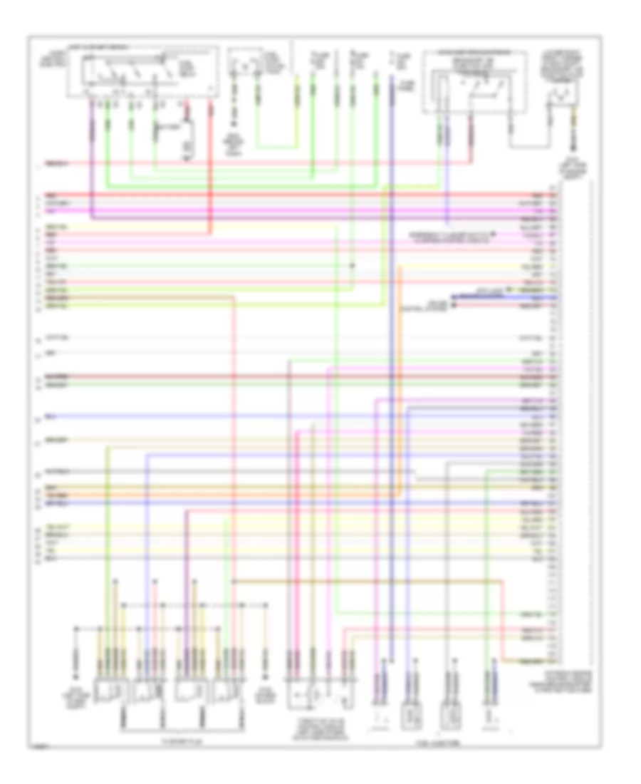
1.8L, Engine Performance Wiring Diagram (3 of 3) for Audi A4 Quattro 2001
List of elements for 1.8L, Engine Performance Wiring Diagram (3 of 3) for Audi A4 Quattro 2001:
- (lower right front corner of eng compt) secondary air injection pump motor
- 87f
- 87a
- Anti-lock brakes system
- Battery
- Cruise control system
- Emergency flasher switch & air bag control module
- Fuel injectors
- Fuel pump (in fuel tank)
- Fuel pump relay
- Fuse 15a
- Fuse 20a
- Fuse panel
- G104 (left side of eng compt)
- G104 (left side of engine compt)
- G132 (on eng block)
- G202 (behind left dash)
- Hot in start or run
- Micro center electronic
- Micro central electric
- Motronic engine control module (near brake booster, in protectice case)
- Nca
- Red
- Secondary air injection (air) pump relay
- Throttle valve control module (left side of eng, on intake manifold)
- To spark plug
2.8L
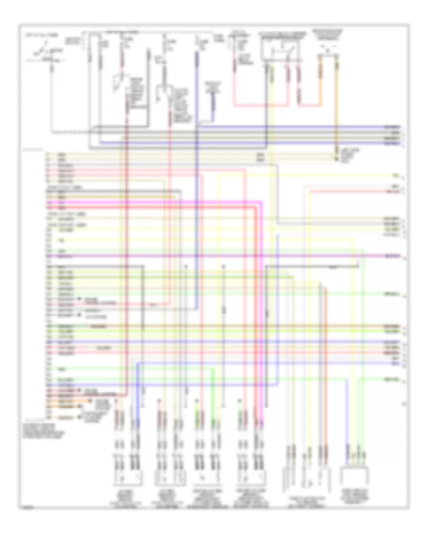
2.8L, Engine Performance Wiring Diagram (1 of 3) for Audi A4 Quattro 2001
List of elements for 2.8L, Engine Performance Wiring Diagram (1 of 3) for Audi A4 Quattro 2001:
- (in 13-way relay carrier) brake booster relay
- (left side of eng compt) g104
- (m/t)
- (pins 14-17 not used)
- (pins 19-24 not used)
- (pins 7-9 not used)
- 13-way relay carrier
- 20a
- A/c system
- Back-up light switch
- Brake booster vacuum pump (a/t only)
- Brake- light switch (above brake pedal, on bracket)
- Clutch vacuum vent valve switch (above clutch pedal, on bracket)
- Cruise control system
- Fuse 10a
- Fuse 15a
- Fuse panel
- Heated oxygen sensor 1 (behind right cylinder head, on exhaust manifold)
- Heated oxygen sensor 2 (behind right cylinder head, on exhaust manifold)
- Hot at all times
- Ignition switch
- Instrument cluster system
- Mass airflow (maf) sensor (in air cleaner assembly)
- Motronic engine control module (near brake booster, in protective case)
- Nca
- Off
- Oxygen sensor 1 (behind 3-way catalytic converter)
- Oxygen sensor 2 (behind 3-way catalytic converter)
- Red
- Run
- Start
- Throttle position (tp) sensor (on throttle body)
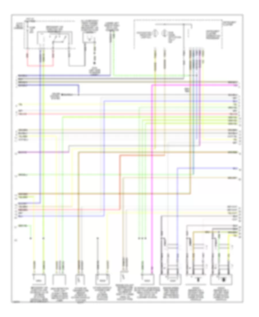
2.8L, Engine Performance Wiring Diagram (2 of 3) for Audi A4 Quattro 2001
List of elements for 2.8L, Engine Performance Wiring Diagram (2 of 3) for Audi A4 Quattro 2001:
- (in lower right front corner of eng compt) secondary air injection pump motor
- (under left side of dash) data link connector
- 3-way relay carrier
- Cruise control system
- Engine coolant temperature (ect) sensor (on rear of right cylinder head, on coolant pipe)
- Engine speed (rpm) sensor (left side of transmission bell housing)
- Evaporative emission (evap) canister purge regulator valve (on top of air cleaner housing)
- Fuse 50a
- G104 (left side of engine compt)
- Hot at all times
- Instrument cluster
- Instrument cluster combination processor
- Intake air temperature sensor (in rear of intake manifold, in intake duct)
- Intake manifold change-over valve (on rear of intake manifold)
- Knock sensor (ks) 1 (on right side of eng block, under intake manifold)
- Knock sensor (ks) 2 (on left side of eng block, under intake manifold)
- Leak detection pump (ldp) (in right rear wheelhousing, above plastic liner)
- Malfunction indicator lamp (mil)
- Nca
- Pwr accel activation fault ind
- Red
- Secondary air injection (air) pump relay
- Secondary air injection (air) solenoid valve (on rear of intake manifold, near air intake duct)
- T32/1
- T32/11
- T32/13
- T32/25
- T32/3
- T32/6
- T32a/14
- T32a/28
2.8L, Engine Performance Wiring Diagram (3 of 3) for Audi A4 Quattro 2001
List of elements for 2.8L, Engine Performance Wiring Diagram (3 of 3) for Audi A4 Quattro 2001:
- (left side of
- 87a
- Anti-lock brakes system
- Battery
- Brake booster pressure sensor (a/t only)
- Camshaft adjustment valve 1 (on rear of right cylinder head)
- Camshaft adjustment valve 2 (on front of left cylinder head)
- Camshaft position (cmp) sensor 1 (rear of left cylinder head)
- Camshaft position (cmp) sensor 2 (front of right cylinder head)
- Cruise control system
- Distributor ignition capacitor
- Dti
- Eng compt)
- Fuel injectors
- Fuel pump (in fuel tank)
- Fuel pump relay
- Fuse 15a
- Fuse 20a
- Fuse panel
- G104
- G202 (behind left dash)
- Hot in start or run micro central electric
- Ignition coil
- Motronic engine control module (near brake booster, in protective case)
- Nca
- Red
- Throttle valve control module (on rear of eng, on intake manifold)
- To spark plugs
- Turn signal switch & air bag control module