ENGINE PERFORMANCE
2.8L
2.8L, Engine Performance Wiring Diagram (1 of 2) for Audi A6 1997

List of elements for 2.8L, Engine Performance Wiring Diagram (1 of 2) for Audi A6 1997:
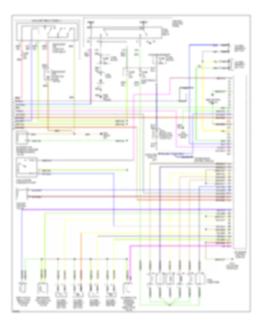
2.8L, Engine Performance Wiring Diagram (2 of 2) for Audi A6 1997
List of elements for 2.8L, Engine Performance Wiring Diagram (2 of 2) for Audi A6 1997: