ENGINE PERFORMANCE
3.0L SC
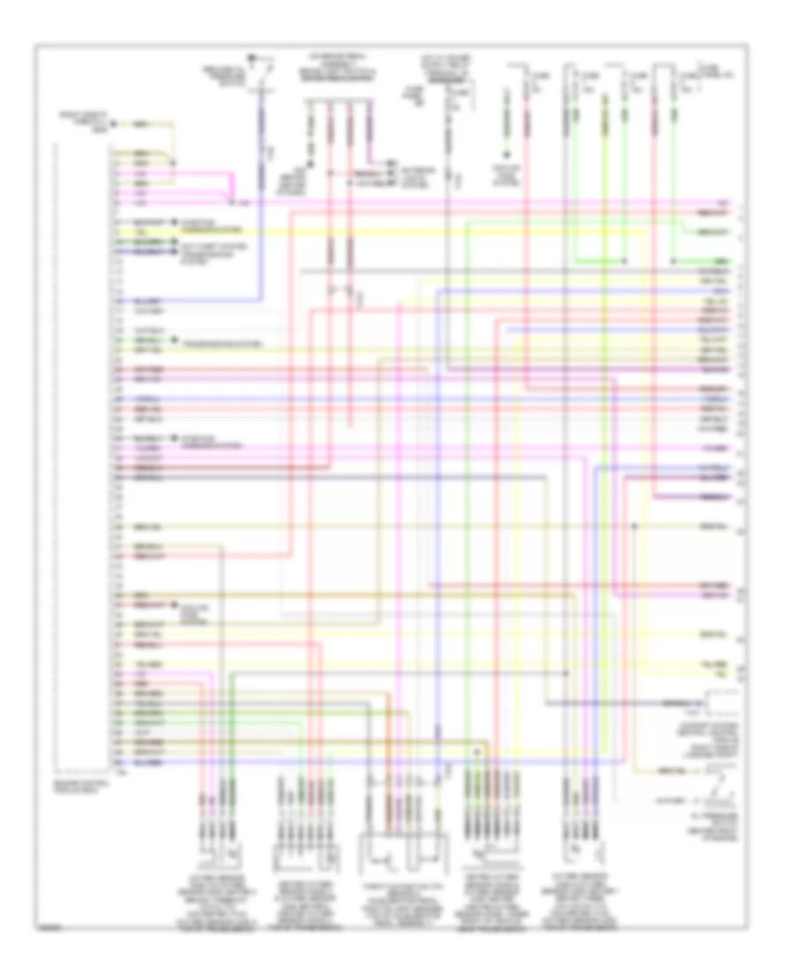
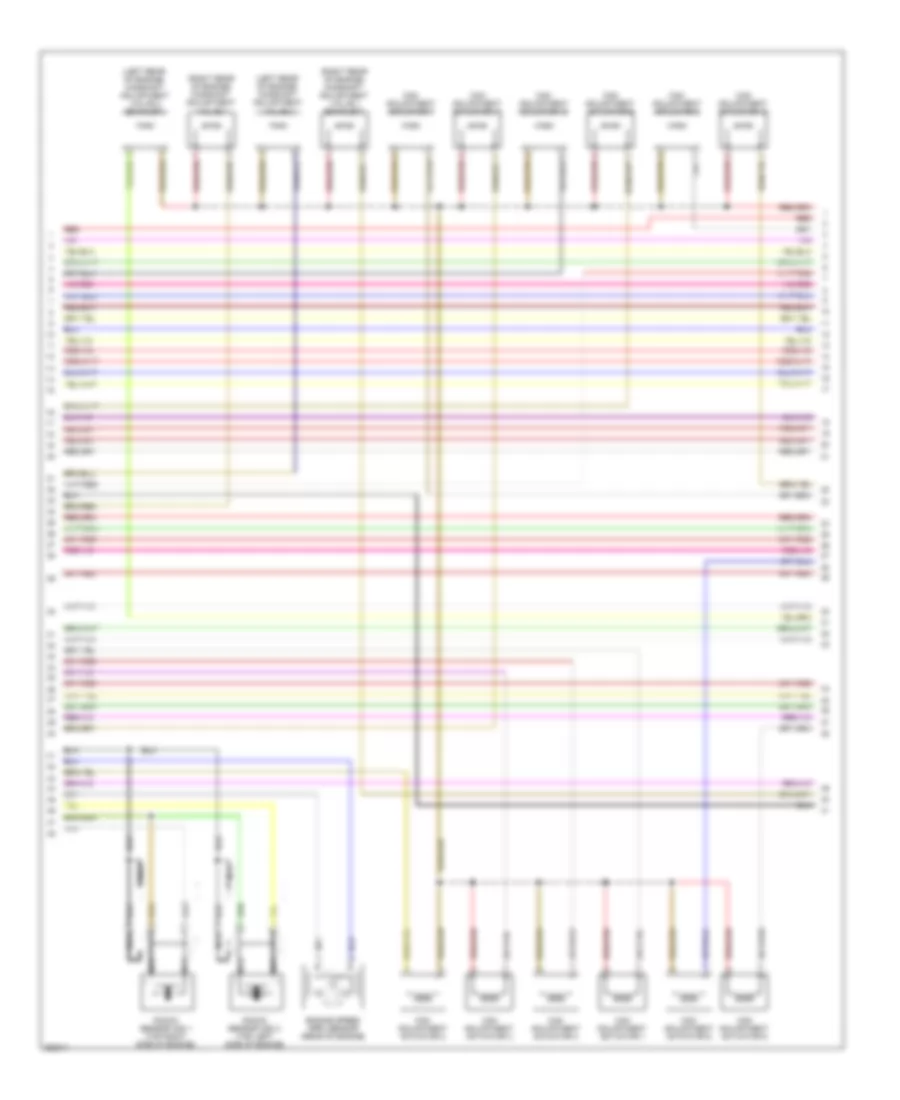
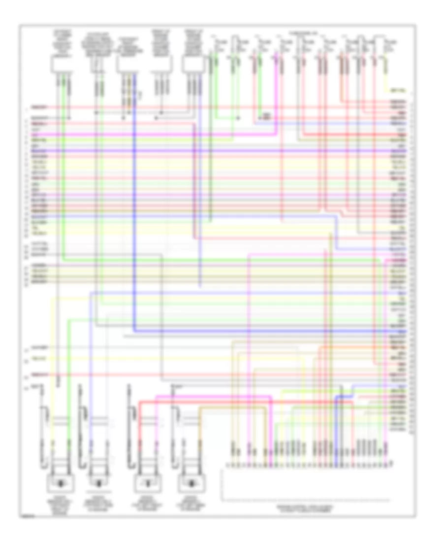
3.0L SC, Engine Performance Wiring Diagram (1 of 6) for Audi A6 3.0T Avant Quattro 2011

List of elements for 3.0L SC, Engine Performance Wiring Diagram (1 of 6) for Audi A6 3.0T Avant Quattro 2011:
- (right side of firewall) g646
- (under transmission oil pan) (a/t) transmission control module (tcm)
- Anti-theft system
- Engine control module (ecm)
- Fuse 10a
- Fuse 110a
- Fuse 15a
- Fuse 20a
- Fuse 5a
- Fuse panel sa
- Heated oxygen sensor (ho2s) 2 & oxygen sensor (o2s) heater 2
- Hot at all times
- Main fuse panel
- Nca
- Oxygen sensor (02s) 2 behind three way catalytic (twc) converter & oxygen sensor (o2s) heater 2 behind threeway catalytic converter (twc) (top of transmission)
- Oxygen sensor (o2s) behind three way catalytic (twc) converter & oxygen sensor (o2s) heater 1 behind threeway catalytic converter (twc) (top of transmission)
- Red
- Relay holder (e-box) (in left plenum chamber e-box)
- Starting/charging system
- T16c
- T170
- T94
- Throttle position (tp) sensor & accelerator pedal position (app) sensor 2 (top of accelerator pedal assembly)
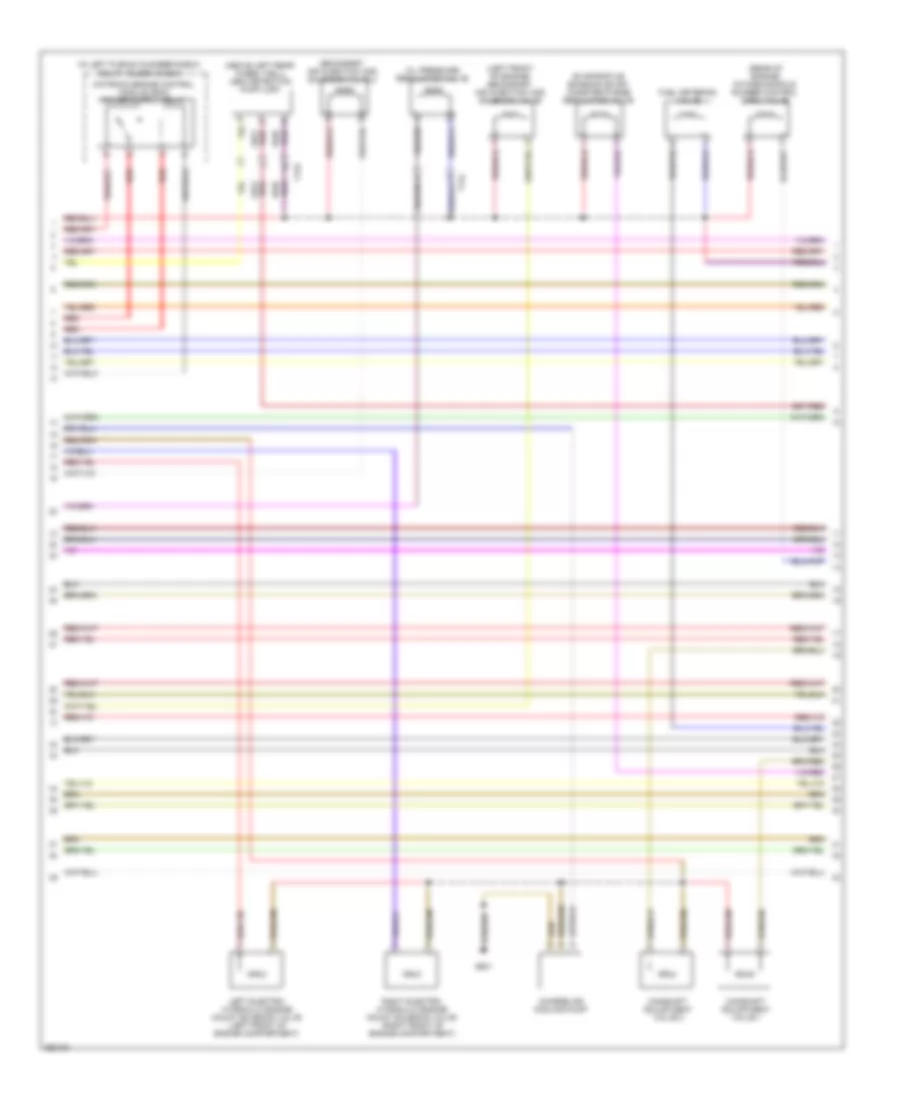
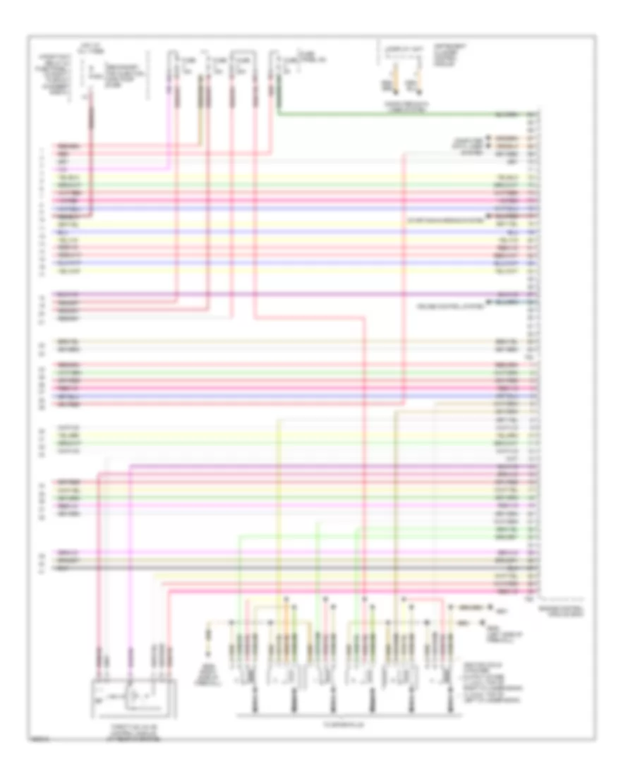
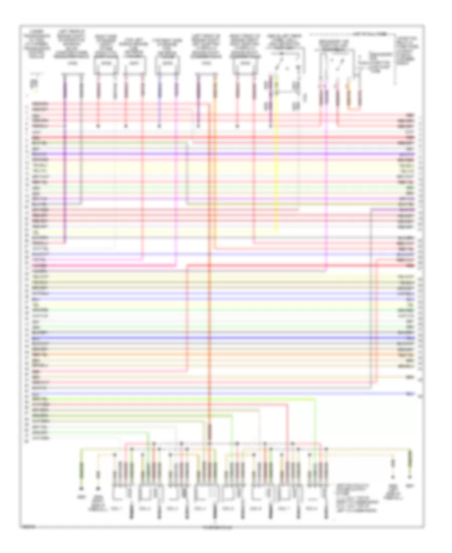
3.0L SC, Engine Performance Wiring Diagram (2 of 6) for Audi A6 3.0T Avant Quattro 2011
List of elements for 3.0L SC, Engine Performance Wiring Diagram (2 of 6) for Audi A6 3.0T Avant Quattro 2011:
- (above left rear wheel well) leak detection pump (ldp)
- (in left plenum chamber e-box) relay holder (e-box)
- (left front of engine) secondary air injection (air) solenoid valve
- (rear of engine) intake manifold runner control (imrc) valve
- Camshaft adjustment valve 1
- Camshaft adjustment valve 2
- Charge air cooling pump
- Evaporative emission (evap) canister purge regulator valve
- Fuel metering valve
- G601
- Left electro- hydraulic engine mount solenoid valve (left front of engine compartment)
- Oil pressure regulation valve
- Red
- Right electro- hydraulic engine mount solenoid valve (right front of engine compartment)
- Secondary air injection (air) solenoid valve 2
- T14l
- T17o
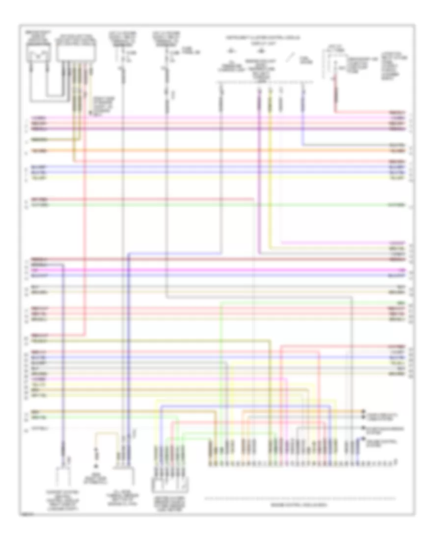
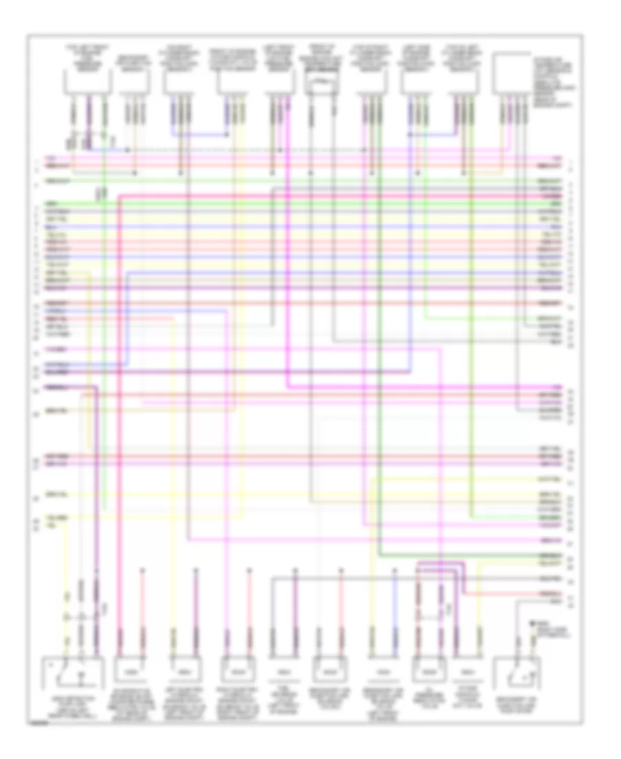
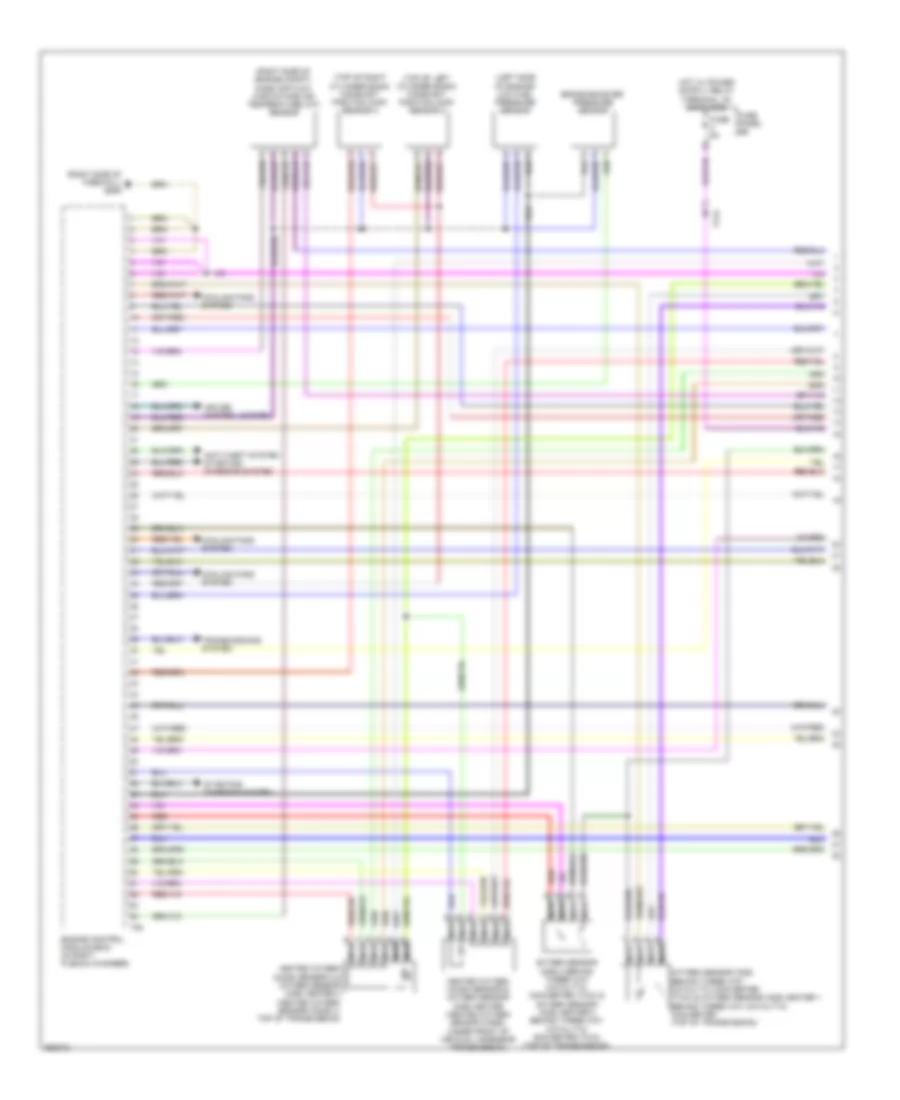
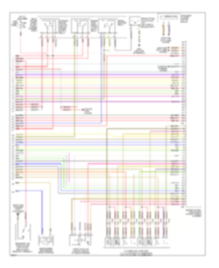
3.0L SC, Engine Performance Wiring Diagram (3 of 6) for Audi A6 3.0T Avant Quattro 2011
List of elements for 3.0L SC, Engine Performance Wiring Diagram (3 of 6) for Audi A6 3.0T Avant Quattro 2011:
- (behind right side of radiator) coolant fan
- (on coolant fan) coolant fan control (fc) control module
- (right side of engine compt, on chassis) g614
- 4 position relay & fuse panel (in right plenum chamber e-box)
- 50a
- Comfort system central control module (right side of luggage compt)
- Computer data lines system
- Cruise control system
- Display unit
- Engine control module (ecm)
- Engine coolant level/ temperature (ecl/ect) warning lamp
- Fuel gauge
- Fuse 5a
- Fuse panel sb
- G646 (right side of firewall)
- Heated oxygen sensor (ho2s) & oxygen sensor (o2s) heater
- Hot at all times
- Instrument cluster control module
- Nca
- Oil level thermal sensor (bottom of engine oil pan)
- Oil pressure warning lamp
- Secondary air injection (air) pump fuse
- Starting/charging system
- T10y
- T17a
- T4c
- T94
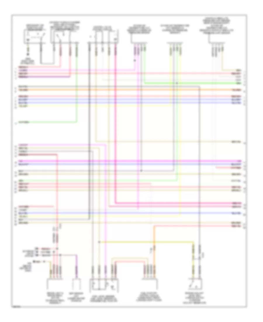
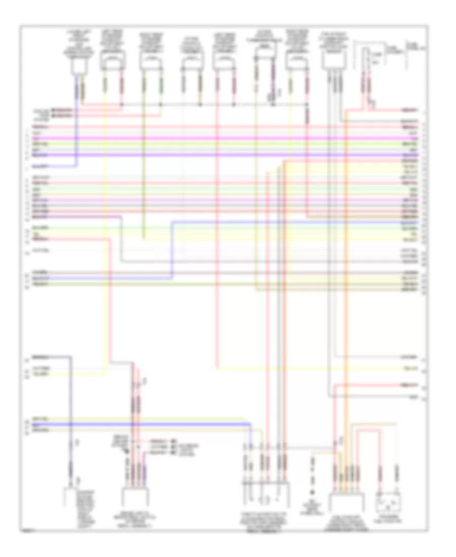
3.0L SC, Engine Performance Wiring Diagram (4 of 6) for Audi A6 3.0T Avant Quattro 2011
List of elements for 3.0L SC, Engine Performance Wiring Diagram (4 of 6) for Audi A6 3.0T Avant Quattro 2011:
- (manifold absolute pressure (map) sensor: rear of engine compt) intake air temperature (iat) sensor & manifold absolute pressure (map) sensor
- (on right plenum chamber e-box relay panel) secondary air injection (air) pump relay
- Brake light & brake pedal switch (on brake pedal assembly)
- Control valve control module
- Engine coolant level (ecl) warning switch (in engine coolant reservoir)
- Esp sensor unit (under center console)
- Exterior lights system
- Fuel level sender, fuel level sensor 2 & transfer fuel pump (fp)
- Fuel pump (fp) control module (under right front luggage compt floor)
- G45 (behind center of dash)
- G646 (right side of firewall)
- Intake air temperature (iat) sensor & charge air pressure sensor
- Intake air temperature (iat) sensor 2 & charge air pressure sensor 2
- Secondary air injection (air) pump motor
- T17a
- T17o
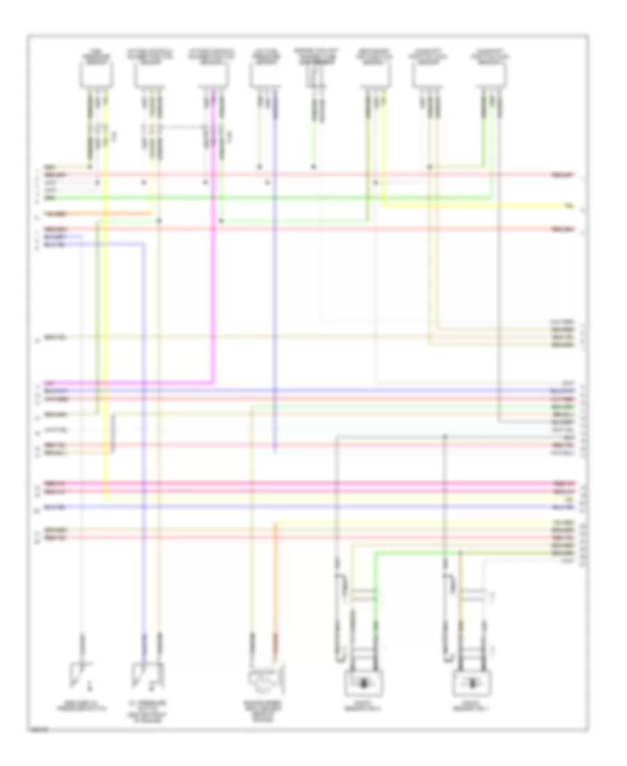
3.0L SC, Engine Performance Wiring Diagram (5 of 6) for Audi A6 3.0T Avant Quattro 2011
List of elements for 3.0L SC, Engine Performance Wiring Diagram (5 of 6) for Audi A6 3.0T Avant Quattro 2011:
- Camshaft position (cmp) sensor
- Camshaft position (cmp) sensor 2
- Engine coolant temperature (ect) sensor
- Engine speed (rpm) sensor (rear of engine)
- Fuel pressure sensor
- Intake manifold runner position sensor
- Intake manifold runner position sensor 2
- Knock sensor (ks) 1
- Knock sensor (ks) 2
- Low fuel pressure sensor
- Nca
- Oil pressure switch (center front of engine)
- Reduced oil pressure switch
- Secondary air injection sensor 1
- T14k
- T14l
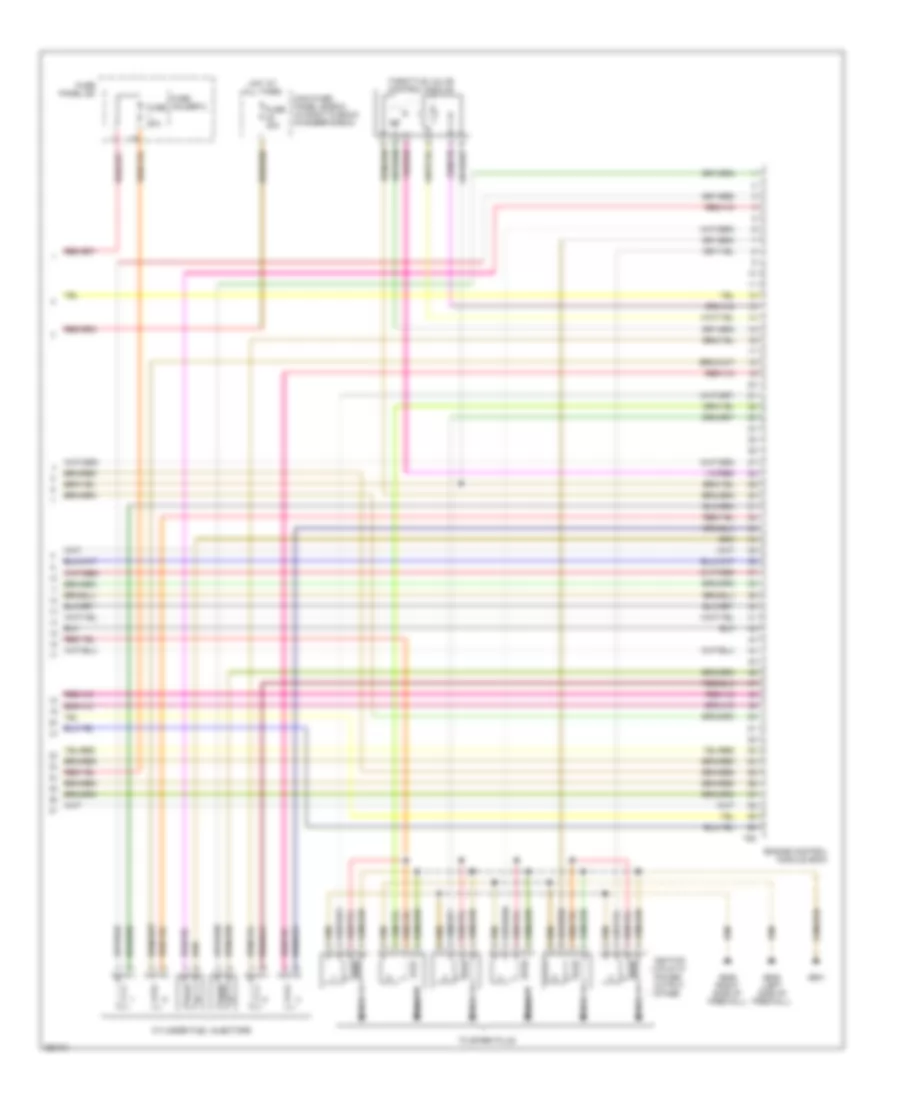
3.0L SC, Engine Performance Wiring Diagram (6 of 6) for Audi A6 3.0T Avant Quattro 2011
List of elements for 3.0L SC, Engine Performance Wiring Diagram (6 of 6) for Audi A6 3.0T Avant Quattro 2011:
- Cylinder fuel injectors
- Engine control module (ecm)
- Fuse 20a
- Fuse 40a
- Fuse holder 2
- Fuse panel sc
- G601
- G645 (left side of firewall)
- G646 (right side of firewall)
- Hot at all times
- Ignition coils w/ power output stage
- Main fuse panel (e-box) (in right plenum chamber e-box)
- Nca
- T60
- Throttle valve control module
- To spark plug
3.2L
3.2L, Engine Performance Wiring Diagram (1 of 5) for Audi A6 3.0T Avant Quattro 2011
List of elements for 3.2L, Engine Performance Wiring Diagram (1 of 5) for Audi A6 3.0T Avant Quattro 2011:
- (on brake pedal assembly) brake light switch & brake pedal switch
- (right side of firewall) g646
- Anti-theft system
- Comfort system central control module (right side of luggage compt)
- Cooling fans system
- Engine control module (ecm)
- Exterior lights system
- Fuse 15a
- Fuse 5a
- Fuse panel sa
- Fuse panel sb
- G45 (behind center of dash)
- Heated oxygen sensor (h02s) & oxygen sensor (02s) heater (heated oxygen sensor (ho2s): under front of vehicle, near transmission)
- Heated oxygen sensor (h02s) 2 & oxygen sensor (02s) heater 2 (heated oxygen sensor (ho2s) 2: top of transmission)
- Nca
- Oil pressure switch (center front of engine)
- Oxygen sensor (o2s) & oxygen sensor (o2s) heater 1 behind three way catalytic converter (twc) (oxygen sensor (o2s): top of transmission)
- Oxygen sensor (o2s) 2 & oxygen sensor (o2s) heater 2 behind threeway catalytic converter (twc) (oxygen sensor (o2s) 2: top of transmission)
- Red
- Reduced oil pressure switch
- Starting/ charging system
- T10y
- T14c
- T17a
- T17o
- T94
- Throttle position (tp) sensor & accelerator pedal position (app) sensors (top of accelerator pedal assembly)
- Transmissions system
3.2L, Engine Performance Wiring Diagram (2 of 5) for Audi A6 3.0T Avant Quattro 2011
List of elements for 3.2L, Engine Performance Wiring Diagram (2 of 5) for Audi A6 3.0T Avant Quattro 2011:
- (front of engine) engine coolant temperature (ect) sensor
- (front of engine) intake manifold tuning (imt) valve position sensor
- (left front of engine) low fuel pressure sensor
- (left side of engine) camshaft position (cmp) sensor 4
- (on right cylinder bank) camshaft position (cmp) sensor 3
- (top left front of engine) fuel pressure sensor
- (top of left cylinder bank) camshaft position (cmp) sensor 2
- (top of right cylinder bank) camshaft position (cmp) sensor
- Evaporative emission (evap) canister purge regulator valve (at rear of engine compt)
- Fuel metering valve (left front of engine)
- G646 (right side of firewall)
- Intake air temperature (iat) sensor & manifold absolute pressure (map) sensor (rear of engine compt)
- Intake manifold tuning (imt) valve
- Leak detection pump (ldp) (above left rear wheelwell)
- Left electro- hydraulic engine mount solenoid valve (left front of engine compt)
- Oil pressure regulation valve
- Right electro- hydraulic engine mount solenoid valve (right front of engine compt)
- Secondary air injection (air) pump motor
- Secondary air injection (air) solenoid valve (left front of engine)
- Secondary air injection (air) solenoid valve 2
- Secondary air injection sensor 1
- T14c
- T17o
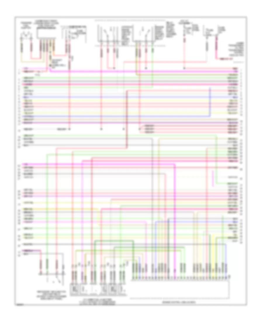
3.2L, Engine Performance Wiring Diagram (3 of 5) for Audi A6 3.0T Avant Quattro 2011
List of elements for 3.2L, Engine Performance Wiring Diagram (3 of 5) for Audi A6 3.0T Avant Quattro 2011:
- (on right rear wheelwell) g51
- (under right front luggage compt floor) fuel pump (fp) control module
- (under transmission oil pan) transmission control module (tcm)
- 10a
- Cylinder fuel injectors (1, 2 & 3: on right cylinder bank) (4, 5 & 6: on left cylinder bank)
- Engine control module (ecm)
- Fuse 10a
- Fuse 110a
- Fuse 30a
- Fuse holder
- Fuse panel sa
- Fuse panel sc
- Hot at all times
- Main fuse panel
- Red
- Relay holder (e-box) (in left plenum chamber e-box)
- Secondary air injection (air) pump relay (on right plenum chamber e-box relay panel)
- T14c
- T170
- T17o
- T60
- T6i
- Transfer fuel pump (fp)
3.2L, Engine Performance Wiring Diagram (4 of 5) for Audi A6 3.0T Avant Quattro 2011
List of elements for 3.2L, Engine Performance Wiring Diagram (4 of 5) for Audi A6 3.0T Avant Quattro 2011:
- (left rear of engine) camshaft adjustment valve 2
- (left rear of engine) camshaft adjustment valve 2 (exhaust)
- (right rear of engine) camshaft adjustment valve 1
- (right rear of engine) camshaft adjustment valve 1 (exhaust)
- Cam adjustment actuator 1
- Cam adjustment actuator 10
- Cam adjustment actuator 11
- Cam adjustment actuator 12
- Cam adjustment actuator 2
- Cam adjustment actuator 3
- Cam adjustment actuator 4
- Cam adjustment actuator 5
- Cam adjustment actuator 6
- Cam adjustment actuator 7
- Cam adjustment actuator 8
- Cam adjustment actuator 9
- Engine speed (rpm) sensor (rear of engine)
- Knock sensor (ks) 1 (top right side of engine)
- Knock sensor (ks) 2 (top left side of engine)
- Nca
- Red
3.2L, Engine Performance Wiring Diagram (5 of 5) for Audi A6 3.0T Avant Quattro 2011
List of elements for 3.2L, Engine Performance Wiring Diagram (5 of 5) for Audi A6 3.0T Avant Quattro 2011:
- 4-position relay & fuse panel (in right plenum chamber e-box)
- 50a
- Computer data lines system
- Cruise control system
- Display unit
- Engine control module (ecm)
- Fuse 15a
- Fuse 30a
- Fuse 5a
- Fuse panel sa
- G601
- G645 (left side of firewall)
- G646 (right side of firewall)
- Hot at all times
- Ignition coils w/power output stage (1, 2 & 3: top of right cylinder bank) (4, 5 & 6: top of left cylinder bank)
- Instrument cluster control module
- Nca
- Red
- Secondary air injection (air) pump fuse
- Starting/charging system
- T60
- T94
- Throttle valve control module (at rear of engine)
- To spark plug
4.2L
4.2L, Engine Performance Wiring Diagram (1 of 5) for Audi A6 3.0T Avant Quattro 2011
List of elements for 4.2L, Engine Performance Wiring Diagram (1 of 5) for Audi A6 3.0T Avant Quattro 2011:
- (left side of engine) low fuel pressure sensor
- (right side of engine compt) mass air flow (maf)/intake air temperature (iat) sensor
- (right side of firewall) g646
- (top of left cylinder bank) camshaft position (cmp) sensor 2
- (top of right cylinder bank) camshaft position (cmp) sensor 4
- Anti-theft system starting/ charging system
- Brake booster pressure sensor
- Cooling fans system
- Cruise control system
- Engine control module (ecm) (in right plenum chamber)
- Fuse 5a
- Fuse panel sb
- Heated oxygen (ho2s) sensor & oxygen sensor (o2s) heater (heated oxygen sensor (ho2s): under front of vehicle, undenear transmission)
- Heated oxygen (ho2s) sensor 2 & oxygen sensor (o2s) heater 2 (heated oxygen sensor (ho2s) 2: top of transmission)
- Nca
- Oxygen sensor (o2s) 2 behind three way catalytic converter (twc) & oxygen sensor (o2s) heater 2 behind three way catalytic converter (twc) (top of transmission)
- Oxygen sensor (o2s) behind three way catalytic converter (twc) & oxygen sensor (o2s) heater 1 behind three way catalytic converter (top of transmission)
- Red
- Starting/ charging system
- T17a
- T94
- Transmissions system
4.2L, Engine Performance Wiring Diagram (2 of 5) for Audi A6 3.0T Avant Quattro 2011
List of elements for 4.2L, Engine Performance Wiring Diagram (2 of 5) for Audi A6 3.0T Avant Quattro 2011:
- (behind center of dash) g45
- (left rear of engine) camshaft adjustment valve 2
- (left rear of engine) camshaft adjustment valve 2 (exhaust)
- (lower left front of engine) map controlled engine cooling thermostat
- (right rear of engine) camshaft adjustment valve 1
- (right rear of engine) camshaft adjustment valve 1 (exhaust)
- (top of right cylinder bank) camshaft position (cmp) sensor
- Brake light & brake pedal switch (on brake pedal assembly)
- Comfort system central control module (right side of luggage compt)
- Cooling fans system
- Exterior lights system
- Fuel pump (fp) control module (under right front luggage compt floor)
- Fuse 30a
- Fuse holder 2
- Fuse panel sc
- G51 (on right rear wheelwell)
- Intake manifold
- Intake manifold tuning (imt) valve
- T10y
- T14l
- T17o
- T7a
- T7o
- Throttle position (tp) & accelerator pedal position (app) sensor 2 (on accelerator pedal assembly)
- Transfer fuel pump (fp)
- Tuning (imt) valve 2
4.2L, Engine Performance Wiring Diagram (3 of 5) for Audi A6 3.0T Avant Quattro 2011
List of elements for 4.2L, Engine Performance Wiring Diagram (3 of 5) for Audi A6 3.0T Avant Quattro 2011:
- (front of engine) intake manifold runner position sensor
- (front of engine) intake manifold runner position sensor 2
- (in coolant pipe at rear of engine compt) engine coolant temperature (ect) sensor
- (on right cylinder bank) camshaft position (cmp) sensor 3
- (top right front of engine) fuel pressure sensor
- Engine control module (ecm) (in right plenum chamber)
- Fuse 10a
- Fuse 15a
- Fuse 30a
- Fuse 5a
- Fuse panel sa
- Knock sensor (ks) 1 (top right front of engine)
- Knock sensor (ks) 2 (top right side of engine)
- Knock sensor 3 (top left front of engine)
- Knock sensor 4 (top left rear of engine)
- Nca
- Red
- T14k
- T60
4.2L, Engine Performance Wiring Diagram (4 of 5) for Audi A6 3.0T Avant Quattro 2011
List of elements for 4.2L, Engine Performance Wiring Diagram (4 of 5) for Audi A6 3.0T Avant Quattro 2011:
- (above left rear wheel well) leak detection pump (ldp)
- (left front of engine compt) left electro- hydraulic engine mount solenoid valve
- (left rear of engine compt) evaporative emission (evap) canister purge regulator valve
- (right front of engine compt) right electro- hydraulic engine mount solenoid valve
- (right side of engine compt) intake air switch- over valve
- (top left side of engine) fuel metering valve 2
- (top right side of engine) fuel metering valve
- (under transmission oil pan) (w/ 6 speed) transmission control module
- 4-position relay & fuse panel (in right plenum chamber e-box)
- 50a
- Coil 1
- Coil 2
- Coil 3
- Coil 4
- Coil 5
- Coil 6
- Coil 7
- Coil 8
- G600
- G601
- G645 (left side of firewall)
- G646 (right side of firewall)
- Hot at all times
- Ignition coils w/ power output stage (1, 2, 3 & 4: top of right cylinder bank) (5, 6, 7 & 8: top of left cylinder bank)
- Nca
- Red
- Secondary air injection (air) pump fuse
- Secondary air injection (air) pump relay
- T17o
- To spark plug
4.2L, Engine Performance Wiring Diagram (5 of 5) for Audi A6 3.0T Avant Quattro 2011
List of elements for 4.2L, Engine Performance Wiring Diagram (5 of 5) for Audi A6 3.0T Avant Quattro 2011:
- (right side of engine compt, on chassis) g614
- Brake booster relay
- Brake system vacuum pump (a/t) (left side of engine compt)
- Computer data lines system
- Cooling fans system
- Cylinder fuel injectors (1, 2, 3 & 4 on right cylinder bank) (5, 6, 7 & 8 on left cylinder bank)
- Display unit
- Engine control module (ecm) (in right plenum chamber)
- Engine speed (rpm) sensor (rear of engine)
- Fuse 110a
- G645 (left side of firewall)
- Hot at all times
- Instrument cluster control module
- Main fuse panel
- Red
- Relay holder (e-box) (in left plenum chamber e-box)
- Secondary air injection (air) pump motor (below right headlight assembly)
- Starting/ charging system
- T14k
- T14l
- T60
- T94
- Throttle valve control module (at rear of engine)