ENGINE PERFORMANCE
2.8L
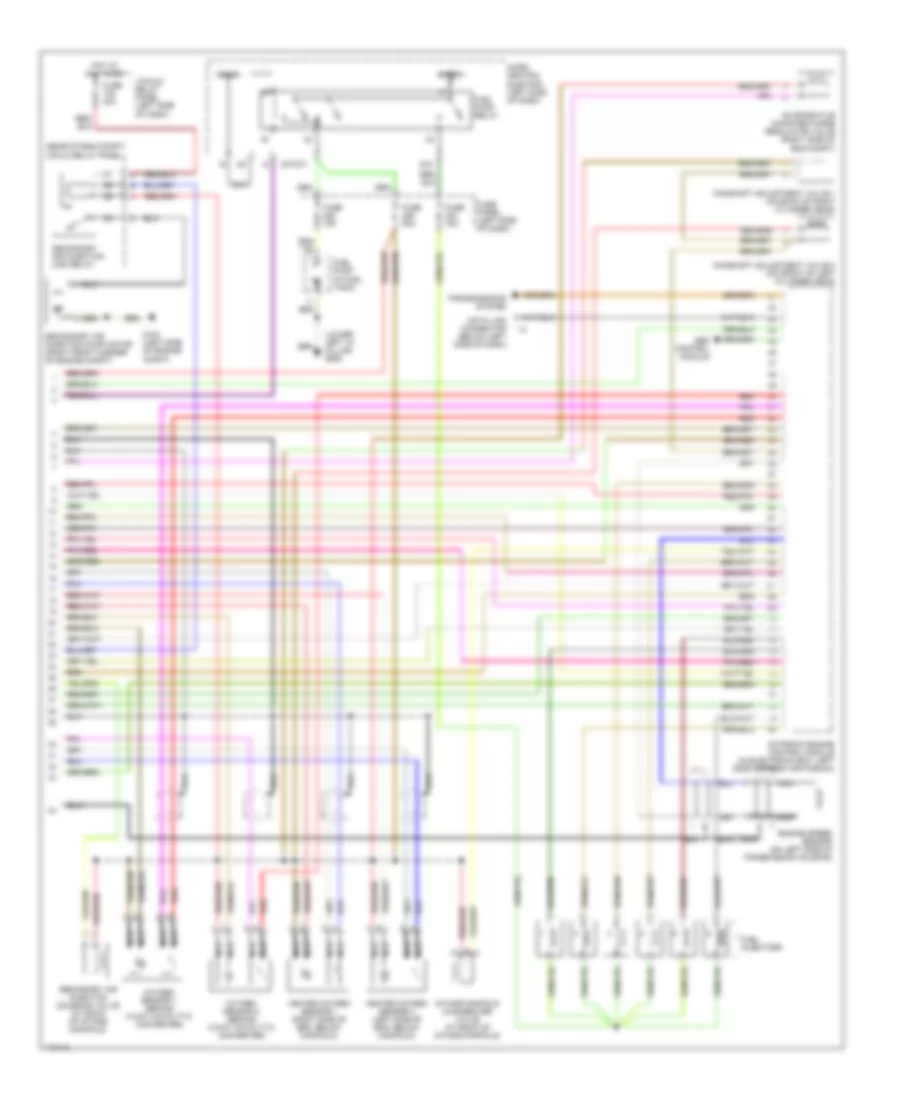
2.8L, Engine Performance Wiring Diagram (1 of 2) for Audi A6 Avant Quattro 1999

List of elements for 2.8L, Engine Performance Wiring Diagram (1 of 2) for Audi A6 Avant Quattro 1999:
- (left side of engine compt)
- (left side of engine compt) g104
- (on air cleaner assembly) mass air- flow sensor
- (on intake manifold, under throttle body) throttle valve control module
- 4wd only
- Air conditioning system
- Anti-lock brakes system
- Bat(30)
- Camshaft position sensor 1 (rear left cylinder head)
- Camshaft position sensor 2 (front of right cylinder head)
- Data link connector (below left side of dash)
- Diagnosis pump (for fuel system)
- Engine coolant temperature sensor (on coolant pipe, behind intake manifold)
- Fuse 15a
- Fuse 20a
- Fuse panel (left side of dash)
- G104
- G900 (lower left "a" pillar)
- Hot in on or acc
- Hot in on or start
- Ignition coil 1
- Ignition coil 2
- Ignition coil 3
- Ignition coils
- Instrument cluster
- Instrument cluster system
- Intake air temperature sensor (in intake air duct, at rear of intake manifold)
- Knock sensor 1 (near right cylinder head)
- Knock sensor 2 (near left cylinder head)
- Malfunction ind lamp
- Micro central electric panel (left side of dash)
- Motronic engine control module (in electronic box, left side of fresh air plenum)
- Nca
- Power output stage
- Red
- Solid state
- Spark plugs 1 & 6
- Spark plugs 2 & 4
- Spark plugs 3 & 5
- T32
- Trans- missions system
- Transmissions system
2.8L, Engine Performance Wiring Diagram (2 of 2) for Audi A6 Avant Quattro 1999
List of elements for 2.8L, Engine Performance Wiring Diagram (2 of 2) for Audi A6 Avant Quattro 1999:
- (lower left "a" pillar) g900
- (rear of eng compt) 3-fold relay panel
- 13-fold relay panel (left side of dash)
- 87f/dti
- 87a
- Abs control module
- Bat(30)
- Camshaft adjustment valve 1 (on back of right cylinder head)
- Camshaft adjustment valve 2 (on front of left cylinder head)
- Data link connector (below left side of dash)
- Engine speed sensor (on left side of transmission housing)
- Evaporative canister purge regulator valve (right side of eng compt)
- Fuel injectors
- Fuel pump (in fuel tank)
- Fuel pump relay
- Fuse 15a
- Fuse 30a
- Fuse 40a
- Fuse panel (left side of dash)
- G104 (left side of engine compt)
- Heated oxygen sensor 1 (right side of eng, below manifold)
- Heated oxygen sensor 2 (left side of eng, below manifold)
- Hot at all times
- Ign(15)
- Intake manifold changeover valve (at back of intake manifold)
- Micro central electric (left side of dash)
- Motronic engine control module (in electronic box, left side of fresh air plenum)
- Nca
- Oxygen sensor 1 (behind 3-way catalytic converter)
- Oxygen sensor 2 (behind 3-way catalytic converter)
- Red
- Secondary air injection (air) relay
- Secondary air injection pump motor (right front corner of engine compt)
- Secondary air injection solenoid valve (at back of intake manifold)
- Transmissions system