ENGINE PERFORMANCE
4.2L
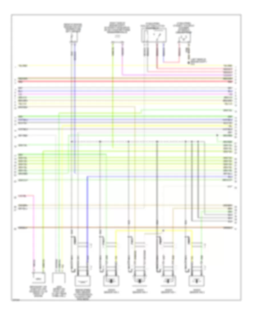
4.2L, Engine Performance Wiring Diagram (1 of 4) for Audi S4 Quattro 2009

List of elements for 4.2L, Engine Performance Wiring Diagram (1 of 4) for Audi S4 Quattro 2009:
- (left rear of engine compt) g12
- (partial)
- 14a
- 43a
- Brake- light switch
- Clutch pedal switch (m/t)
- E-box relay carrier
- Engine control module (in e-box, in plenum chamber)
- Fuse 10a
- Fuse 15a
- Fuse 40a
- Fuse holder
- G12 (left rear of engine compt)
- Heated oxygen sensor
- Heated oxygen sensor 2
- Hot at all times
- Hot in on or start
- Mass airflow (maf) sensor (on intake air duct)
- Oxygen sensor
- Oxygen sensor 2
- Red
- Secondary air injection (air) pump relay
- Secondary air injection pump motor (right front of engine compt)
- Steering column electronic systems control module
- T121
- T16a
- Throttle position (tp) & accelerator pedal position (app) sensors
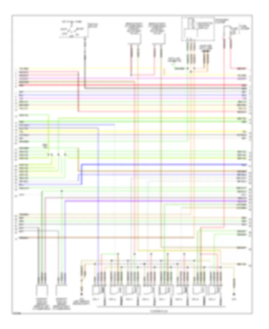
4.2L, Engine Performance Wiring Diagram (2 of 4) for Audi S4 Quattro 2009
List of elements for 4.2L, Engine Performance Wiring Diagram (2 of 4) for Audi S4 Quattro 2009:
- (if equipped) (in e-box, in plenum chamber) after-run coolant pump
- (if equipped) coolant circulation pump relay
- (left rear of engine compt) g12
- (rear of engine) engine coolant temperature (ect) sensor
- (right side of engine compt) evaporative emission (evap) canister purge regulator valve
- Engine speed (rpm) sensor (in transmission housing over ring gear)
- Knock sensor (ks) 1
- Knock sensor (ks) 2
- Knock sensor (ks) 3
- Knock sensor (ks) 4
- Leak detection pump (ldp) (in left rear wheelwell)
- Nca
- Red
- Secondary air injection (air) solenoid valve (front of engine)
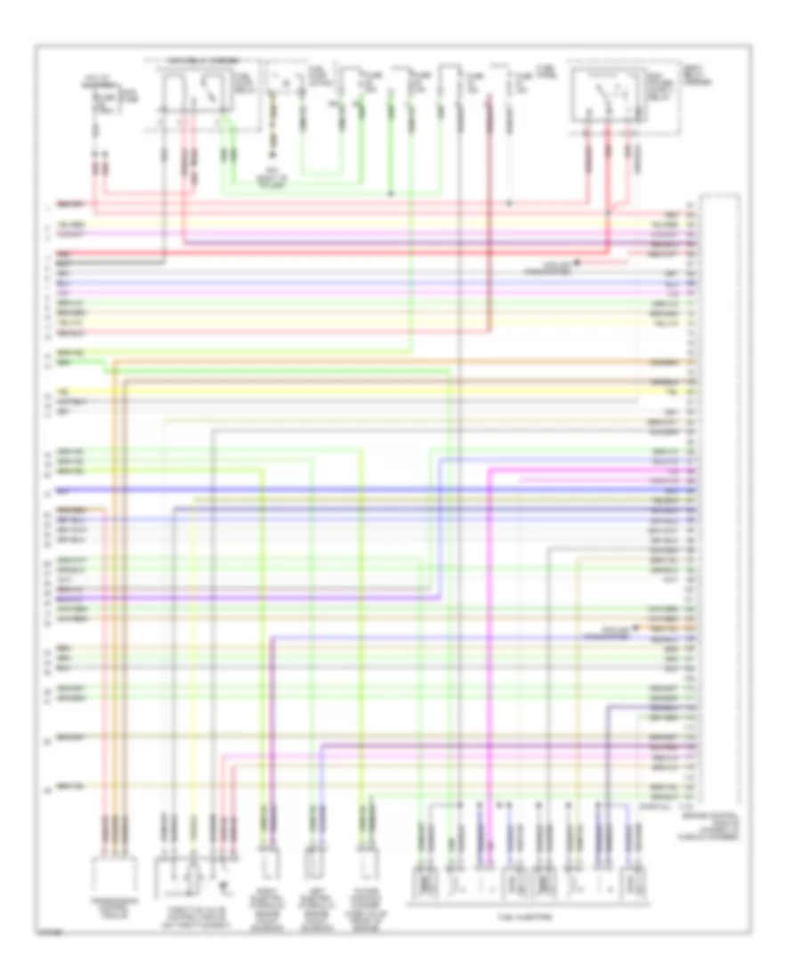
4.2L, Engine Performance Wiring Diagram (3 of 4) for Audi S4 Quattro 2009
List of elements for 4.2L, Engine Performance Wiring Diagram (3 of 4) for Audi S4 Quattro 2009:
- (mil)
- (rear of right cylinder bank) camshaft adjustment valve 1
- (rear of right cylinder bank) camshaft adjustment valve 2
- Acc
- Camshaft position sensor (rear of right cylinder bank)
- Camshaft position sensor 2 (rear of left cylinder bank)
- Coil 1
- Coil 2
- Coil 3
- Coil 4
- Coil 5
- Coil 6
- Coil 7
- Coil 8
- Computer data lines system
- Data link connector
- Fuse 20a
- Fuse holder
- G12 (left rear of engine compt)
- G19
- Hot at all times
- Ignition switch
- Instrument cluster
- Lock
- Malfunction indicator lamp
- Nca
- Off
- Red
- Start
- T32a/12
- T32a/13
- T32a/23
- To spark plug
4.2L, Engine Performance Wiring Diagram (4 of 4) for Audi S4 Quattro 2009
List of elements for 4.2L, Engine Performance Wiring Diagram (4 of 4) for Audi S4 Quattro 2009:
- (partial)
- 9-pin relay carrier
- Cooling fans system
- E-box relay carrier
- Engine control module (in e-box, in plenum chamber)
- Fuel injectors
- Fuel pump motor
- Fuel pump relay
- Fuse 150a
- Fuse 15a
- Fuse 20a
- Fuse panel
- G78 (right "b" pillar)
- Hot at all times
- Intake manifold change- over valve (front of engine)
- Left electro- hydraulic engine mount solenoid
- Main fuse
- Red
- Right electro- hydraulic engine mount solenoid
- T121
- Throttle valve control module (on throttle body)
- Transmission control module