ENGINE PERFORMANCE
3.0L SC
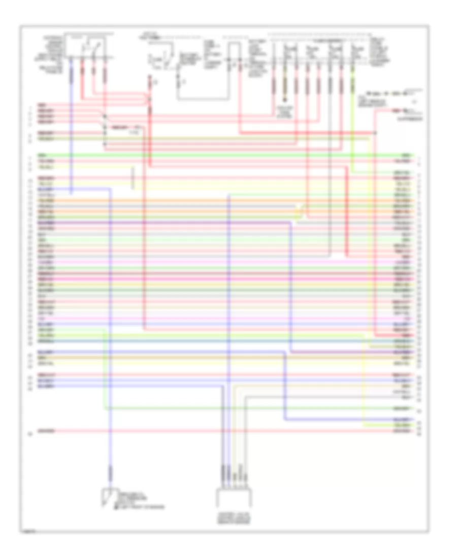
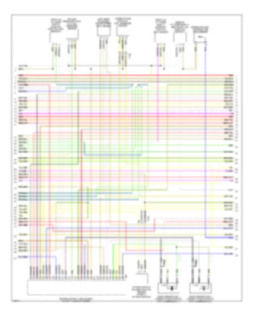
3.0L SC, Engine Performance Wiring Diagram (1 of 8) for Audi S5 Prestige 2014

List of elements for 3.0L SC, Engine Performance Wiring Diagram (1 of 8) for Audi S5 Prestige 2014:
- (left rear of engine compt) g12
- (lower center of left side of engine) left electro- hydraulic engine mount solenoid valve
- (right rear of luggage compt) comfort system central control module
- 12a
- 14a
- A/t
- Accelerator pedal position sensor & sensor 2 (top of accelerator pedal assembly)
- Cooling fans system
- Engine control module (ecm) (in left plenum chamber)
- Fuse 10a
- Fuse 15a
- Fuse 20a
- Fuse 5a
- Fuse carrier
- Fuse carrier 1
- G12 (left rear of engine compt)
- Hot at all times
- M/t
- Nca
- Oil level thermal sensor (bottom of oil pan)
- Oxygen sensor (o2s) 2 behind three way catalytic converter (twc) & oxygen sensor (o2s) 2 behind catalytic converter heater (downstream of cylinder bank 2 catalytic converter)
- Oxygen sensor (o2s) behind three way catalytic converter (twc) & oxygen sensor (o2s) 1 behind catalytic converter heater (downstream of cylinder bank 1 catalytic converter)
- Power distribution system
- Red
- Relay/ fuse panel b (in left plenum chamber e-box)
- Relay/ fuse panel f (right side of luggage compt)
- Right electro hydraulic engine mount solenoid valve (lower center of right side of engine)
- Sensor
- Sensor 2
- Starting/ charging system
- Starting/charging system
- T14e
- T17e
- T17q
- T17r
- T32d
- T94
- Transmissions system
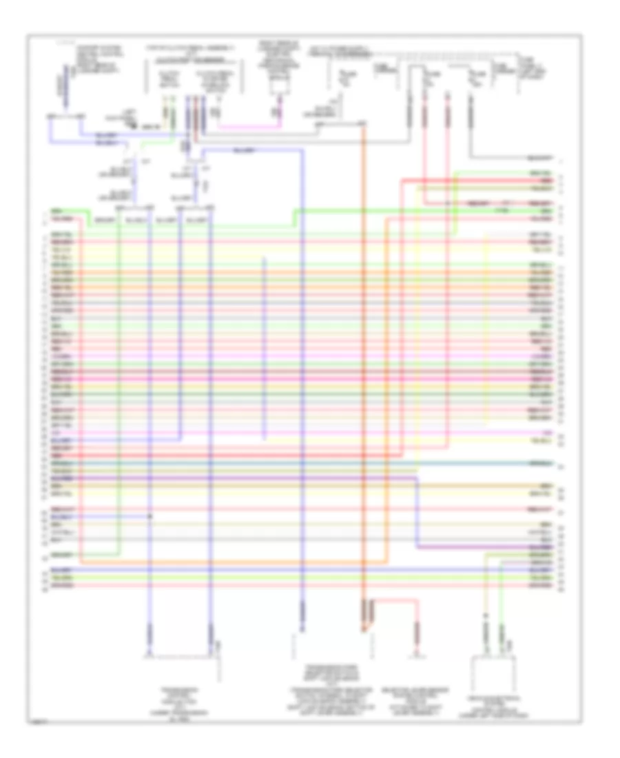
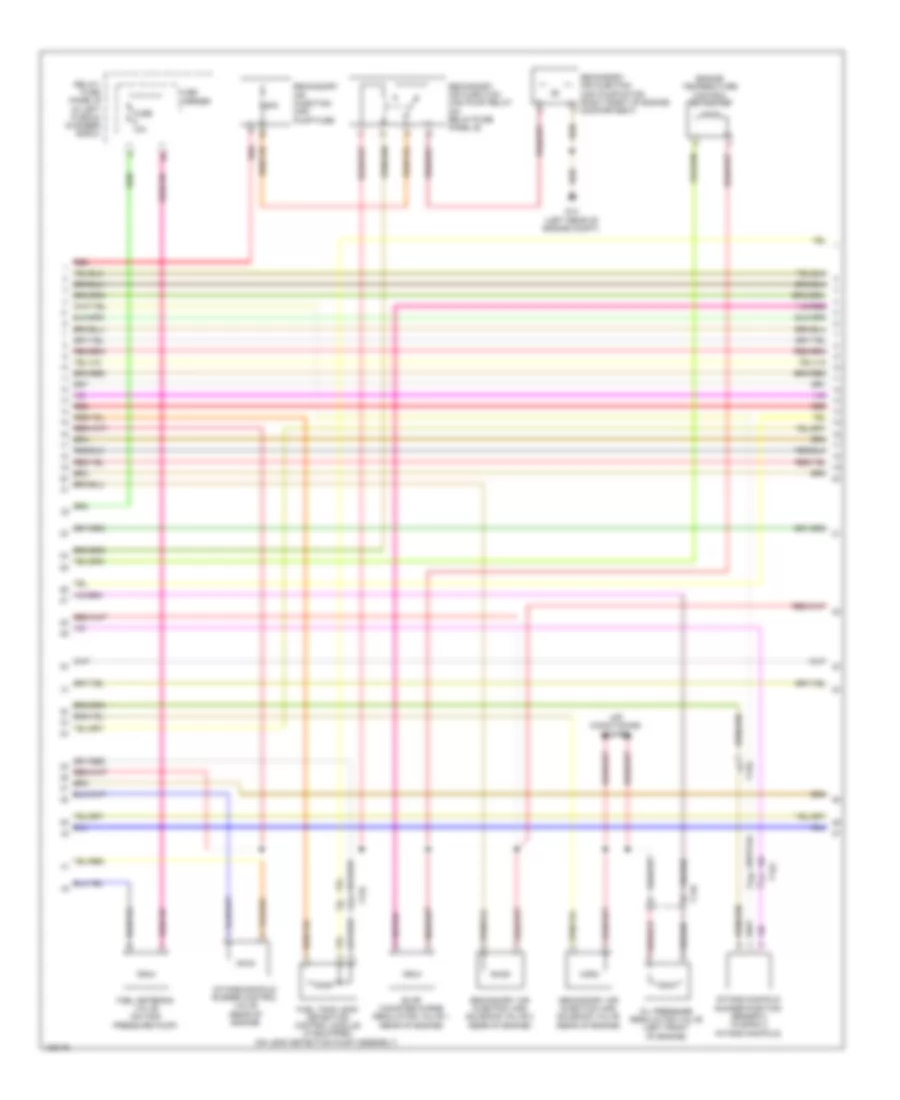
3.0L SC, Engine Performance Wiring Diagram (2 of 8) for Audi S5 Prestige 2014
List of elements for 3.0L SC, Engine Performance Wiring Diagram (2 of 8) for Audi S5 Prestige 2014:
- 10a
- 11a
- 16a
- 17a
- Battery interrupt igniter
- Battery jump start terminal (on terminal 30 wire junction block)
- Control valve control module (rear of engine)
- Cooling fans system
- Fuse 110a
- Fuse 15a
- Fuse 5a
- Fuse carrier 1
- Fuse panel a (on battery, in luggage compt)
- G12 (left rear of engine compt)
- Hot at all times
- Red
- Reduced oil oil pressure switch (left front of engine)
- Relay/ fuse panel b (in left plenum chamber e-box)
- Suppressor
- T17q
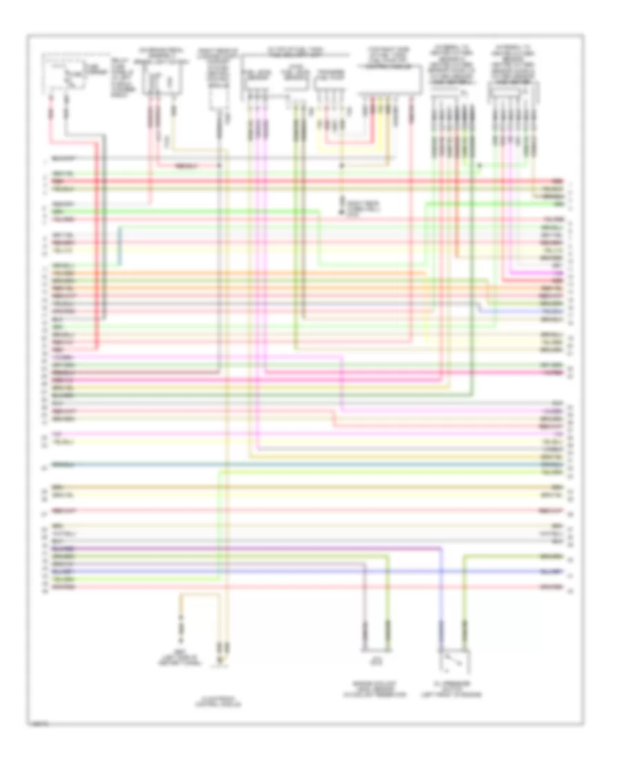
3.0L SC, Engine Performance Wiring Diagram (3 of 8) for Audi S5 Prestige 2014
List of elements for 3.0L SC, Engine Performance Wiring Diagram (3 of 8) for Audi S5 Prestige 2014:
- (left kick panel) g639
- (right rear of luggage compt) electro- mechanical parking brake control module
- (top of clutch pedal assembly) (m/t) clutch position sensor
- 10a
- A/t
- Clutch pedal starter interlock switch
- Clutch pedal switch
- Comfort system central control module (right rear of t32d luggage compt)
- Fuse 25a
- Fuse 5a
- Fuse carrier
- Fuse panel c (left end of dash)
- M/t
- Red
- Selector lever sensor system control module (attached to shift lever assembly)
- T16r
- T17e
- T17q
- T32b
- Transmission control module (tcm) (a/t) (under transmission oil pan)
- Transmission park selector switch & shift lock solenoid (a/t) (transmission park selector switch: integral to shift lock solenoid assembly) (shift lock solenoid: bottom of shift lever assembly)
- Vehicle electrical system control module (under left side of dash)
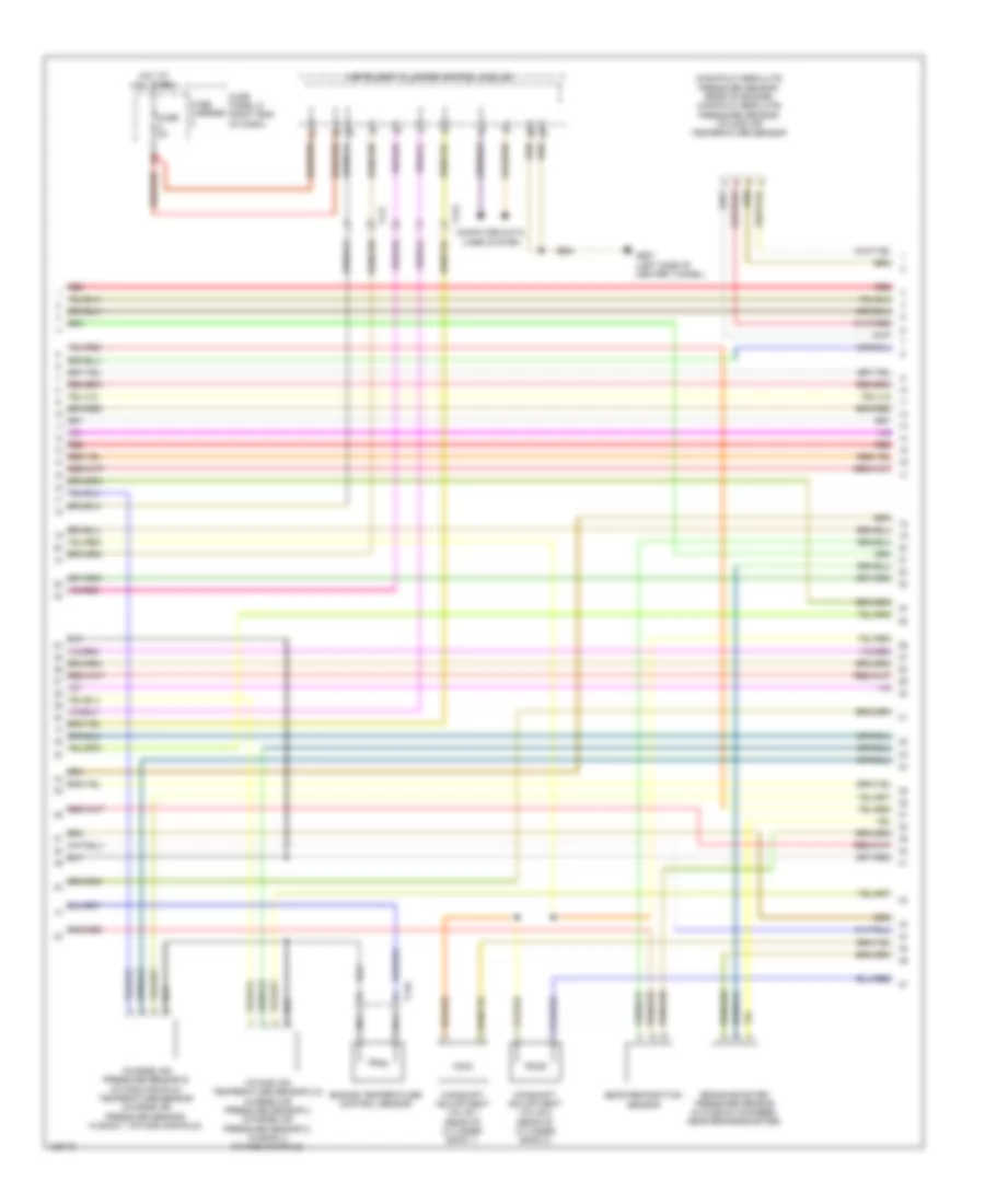
3.0L SC, Engine Performance Wiring Diagram (4 of 8) for Audi S5 Prestige 2014
List of elements for 3.0L SC, Engine Performance Wiring Diagram (4 of 8) for Audi S5 Prestige 2014:
- (awd) fuel level sensor 2
- (in top of fuel tank) fuel delivery unit
- (integral to heated oxygen sensor 2) heated oxygen sensor (ho2s) 2 & oxygen sensor (o2s) heater 2
- (integral to heated oxygen sensor) heated oxygen sensor (ho2s) & oxygen sensor (o2s) heater
- (on brake pedal assembly) brake light switch
- (right rear of luggage compt) comfort system central control module
- (right rear wheelwell) g730
- (top right side of fuel tank) fuel pump (fp) control module
- Climatronic control module
- Coil
- Engine coolant level sensor (in coolant reservoir)
- Fuel level sensor
- Fuse 5a
- Fuse carrier
- G687 (left side of center tunnel)
- Nca
- Oil pressure switch (left front of engine)
- Red
- Relay/ fuse panel b (in left plenum chamber e-box)
- T17e
- T32d
- T4s
- T6r
- Transfer fuel pump
3.0L SC, Engine Performance Wiring Diagram (5 of 8) for Audi S5 Prestige 2014
List of elements for 3.0L SC, Engine Performance Wiring Diagram (5 of 8) for Audi S5 Prestige 2014:
- (manifold absolute pressure sensor: rear of engine) manifold absolute pressure sensor/ intake air temperature sensor
- Brake booster pressure sensor (in plenum chamber, near brake booster)
- Camshaft adjustment valve 1 (rear of cylinder bank 1)
- Camshaft adjustment valve 2 (rear of cylinder bank 2)
- Charge air pressure sensor & intake manifold temperature sensor (charge air pressure sensor: in bank 1 intake manifold)
- Computer data lines system
- Engine temperature control sensor
- Fuse 5a
- Fuse carrier
- Fuse panel d (right end of dash)
- G687 (left side of center tunnel)
- Gear recognition sensor
- Hot at all times
- Instrument cluster control module
- Intake air temperature sensor 2 & charge air pressure sensor 2 (charge air pressure sensor 2: in bank 2 intake manifold)
- Nca
- Red
- T14g
- T17f
- T17g
3.0L SC, Engine Performance Wiring Diagram (6 of 8) for Audi S5 Prestige 2014
List of elements for 3.0L SC, Engine Performance Wiring Diagram (6 of 8) for Audi S5 Prestige 2014:
- (front of cylinder bank 1) camshaft position (cmp) sensor
- (front of cylinder bank 2) camshaft position (cmp) sensor 2
- (left rear of engine) engine speed (rpm) sensor
- (on high pressure pump) low fuel pressure sensor
- (rear of cylinder bank 1) secondary air injection sensor 1
- (under intake manifold) fuel pressure sensor
- Engine control module (ecm) (in left plenum chamber)
- Engine coolant temperature (ect) sensor
- Intake manifold runner position sensor (in bank 1 intake manifold)
- Knock sensor (ks) 1 (under intake manifold, on cylinder bank 1)
- Knock sensor (ks) 2 (under intake manifold, on cylinder bank 2)
- Nca
- Red
- T14e
- T14g
- T60
3.0L SC, Engine Performance Wiring Diagram (7 of 8) for Audi S5 Prestige 2014
List of elements for 3.0L SC, Engine Performance Wiring Diagram (7 of 8) for Audi S5 Prestige 2014:
- 50a
- Air conditioning system
- Engine temperature control actuator
- Evap canister purge regulator valve 1 (rear of engine)
- Fuel metering valve (on high pressure pump)
- Fuel tank leak detection control module (if equipped) (on leak detection pump assembly)
- Fuse 10a
- Fuse carrier
- G12 (left rear of engine compt)
- Intake manifold runner control valve (rear of engine)
- Intake manifold runner position sensor 2 (in bank 2 intake manifold)
- Oil pressure regulation valve (left front of engine)
- Red
- Relay/ fuse panel b (in left plenum chamber e-box)
- Secondary air injection (air) pump fuse
- Secondary air injection (air) pump motor (right front of engine compartment)
- Secondary air injection (air) pump relay (on relay/fuse panel b)
- Secondary air injection (air) solenoid valve (rear of engine)
- Secondary air injection (air) solenoid valve 2 (rear of engine)
- T14e
- T14g
- T17q
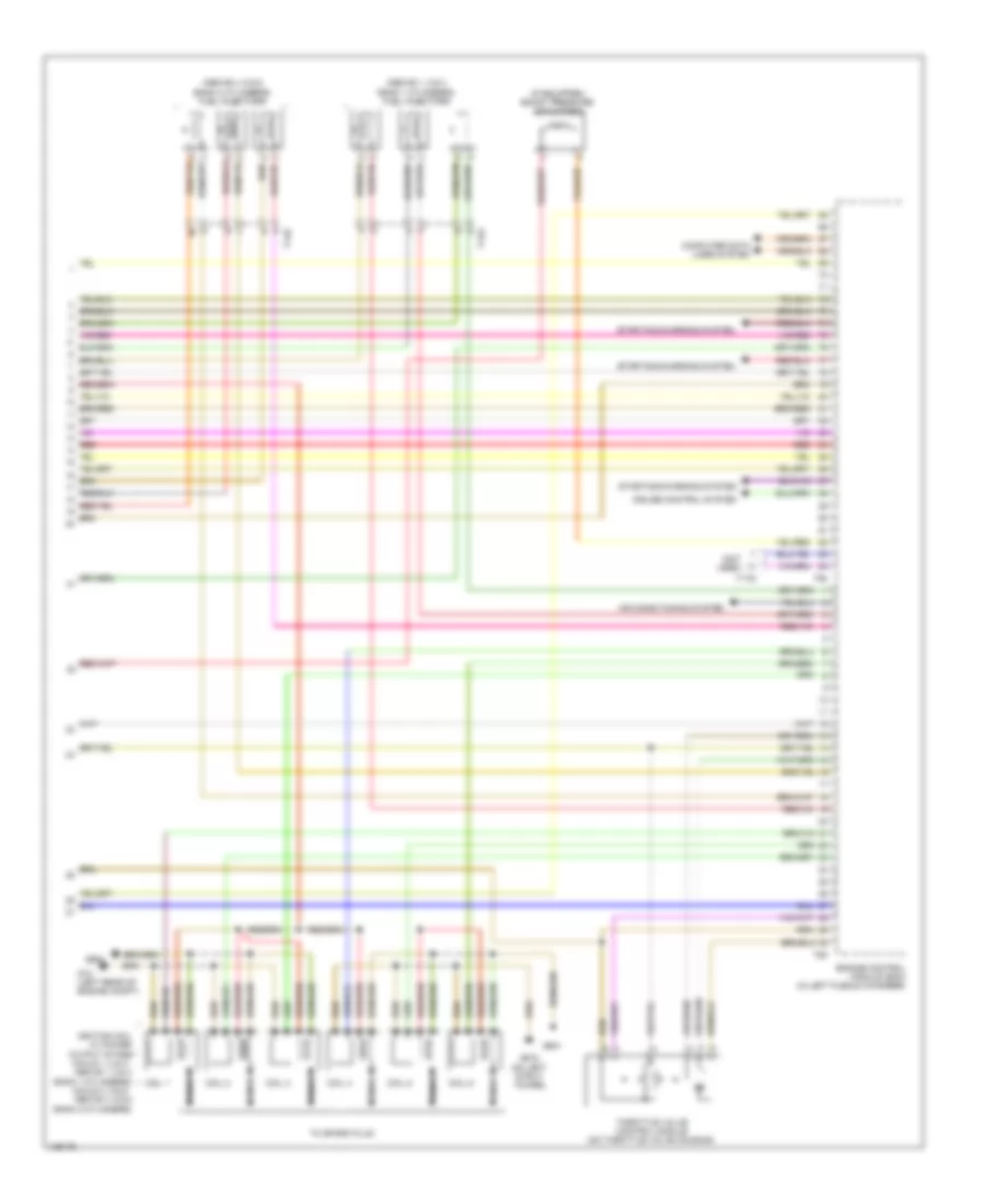
3.0L SC, Engine Performance Wiring Diagram (8 of 8) for Audi S5 Prestige 2014
List of elements for 3.0L SC, Engine Performance Wiring Diagram (8 of 8) for Audi S5 Prestige 2014:
- (above 1, 2 & 3 bank 1 cylinders) fuel injectors
- (above 4, 5 & 6 bank 2 cylinders) fuel injectors
- (if equipped) boost pressure actuator 2
- (not used)
- Air conditioning system
- Coil 1
- Coil 2
- Coil 3
- Coil 4
- Coil 5
- Coil 6
- Computer data lines system
- Cruise control system
- Engine control module (ecm) (in left plenum chamber)
- G12 (left rear of engine compt)
- G600
- G601
- G615 (on left strut tower)
- Ignition coil w/ power output stage (coils 1, 2 & 3 : above 1, 2 & 3 bank 1 cylinders) (coils 4, 5 & 6 : above 4, 5 & 6 bank 2 cylinders)
- Nca
- Red
- Starting/charging system
- T14e
- T14g
- T17q
- T60
- T94
- Throttle valve control module (on throttle valve housing)
- To spark plug