ENGINE PERFORMANCE
5.2L
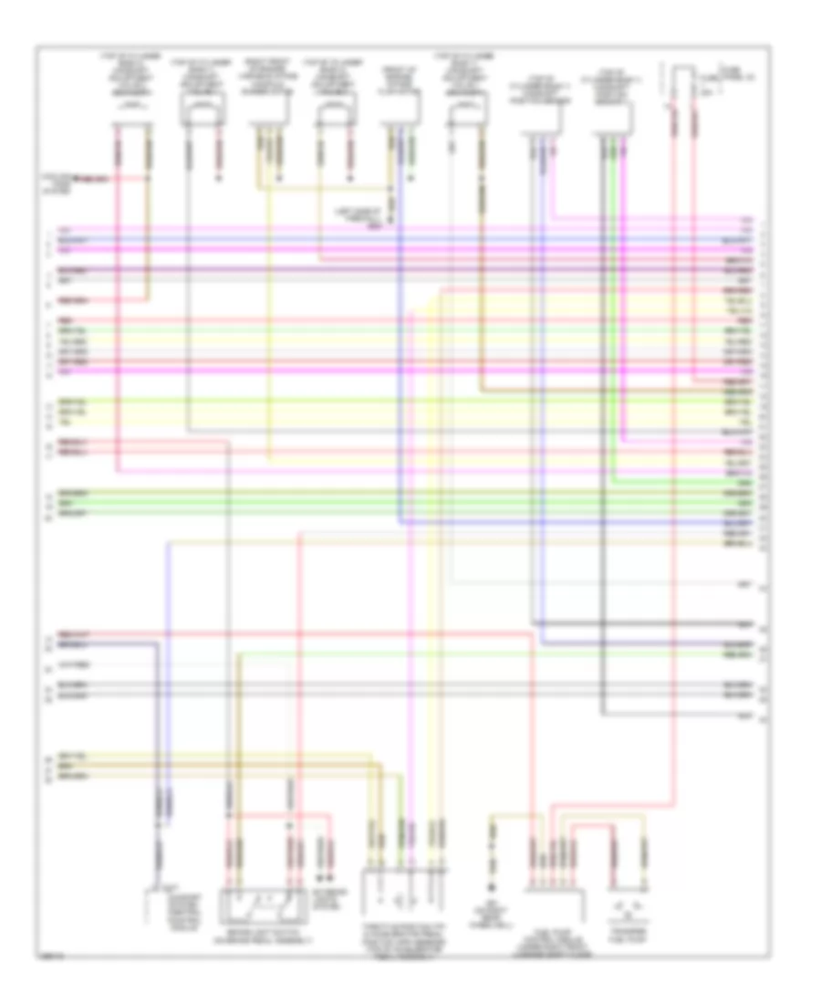
5.2L, Engine Performance Wiring Diagram (1 of 8) for Audi S6 Quattro 2007

List of elements for 5.2L, Engine Performance Wiring Diagram (1 of 8) for Audi S6 Quattro 2007:
- (left side of firewall) g647
- (right in air filter housing) mass air flow (maf)/intake air temperature (iat) sensor
- (right rear of engine) low fuel pressure sensor
- Anti-theft system starting/ charging system
- Brake booster pressure sensor
- Cooling fans system
- Cruise control system
- Engine control module (ecm) i (right rear of engine compt)
- Heated oxygen sensor (in bank 1 exhaust)
- Heated oxygen sensor 2 (in bank 2 exhaust)
- Map controlled engine cooling thermostat
- Nca
- Partial
- Red
- Starting/ charging system
- T94a
- Transmissions system
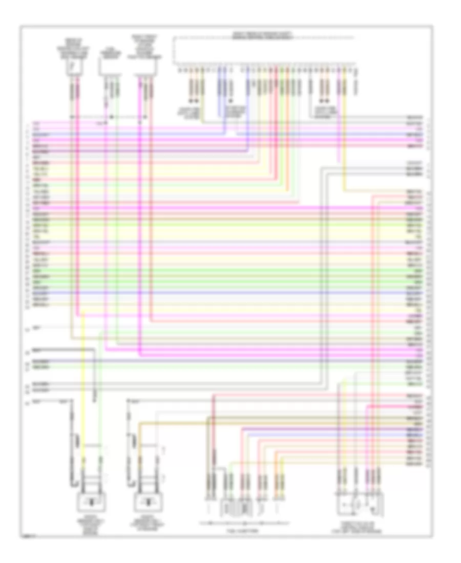
5.2L, Engine Performance Wiring Diagram (2 of 8) for Audi S6 Quattro 2007
List of elements for 5.2L, Engine Performance Wiring Diagram (2 of 8) for Audi S6 Quattro 2007:
- (front of engine) intake flap motor
- (left side of firewall) g647
- (right front of engine) variable intake manifold runner motor
- (top of cylinder bank 1) camshaft adjustment valve 1
- (top of cylinder bank 1) camshaft adjustment valve 1 (exhaust)
- (top of cylinder bank 1) camshaft position sensor
- (top of cylinder bank 1) camshaft position sensor 3
- (top of cylinder bank 2) camshaft adjustment valve 2
- (top of cylinder bank 2) camshaft adjustment valve 2 (exhaust)
- Brake-light switch (on brake pedal assembly)
- Comfort system central control module
- Cooling fans system
- Exterior lights system
- Fuel pump control module (under right front luggage compt floor)
- Fuse 30a
- Fuse panel c2
- G51 (on right rear wheelwell)
- Red
- T10y
- Throttle position (tp) & accelerator pedal position (app) sensors (top of accelerator pedal assembly)
- Transfer fuel pump
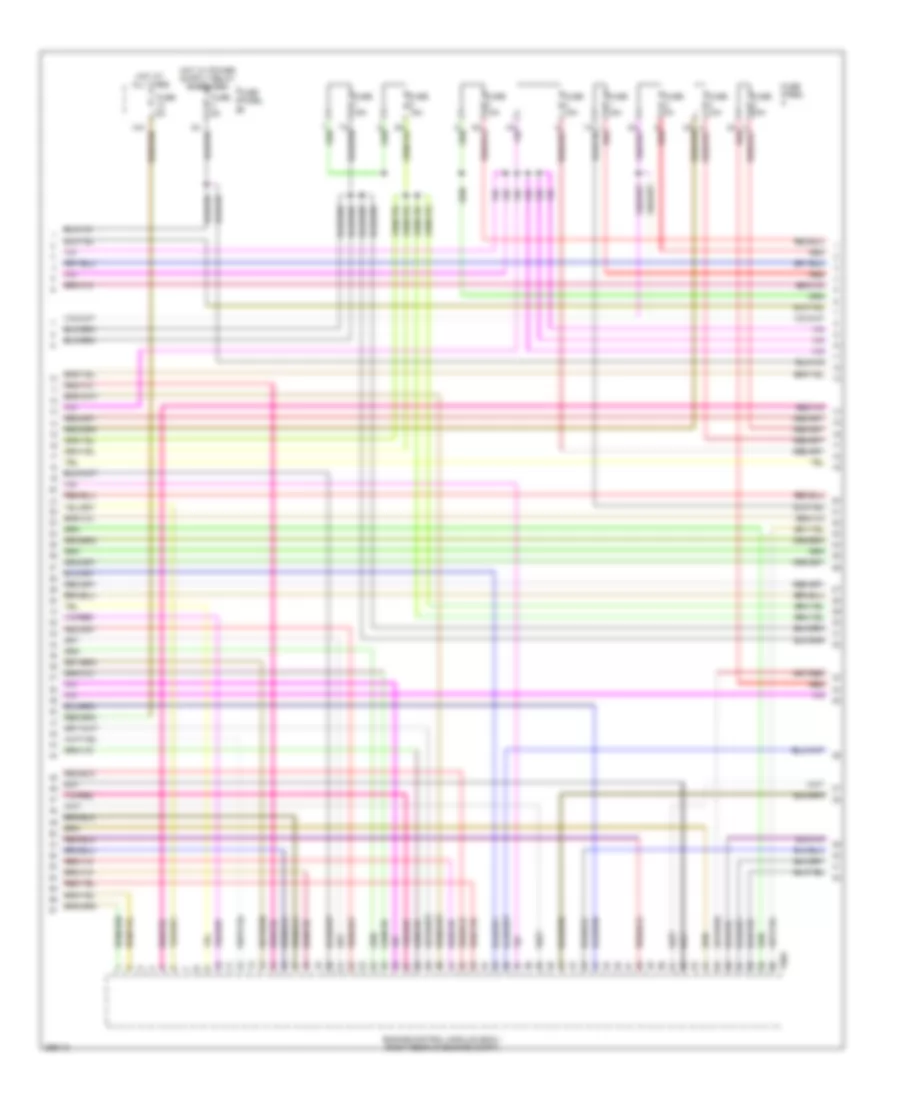
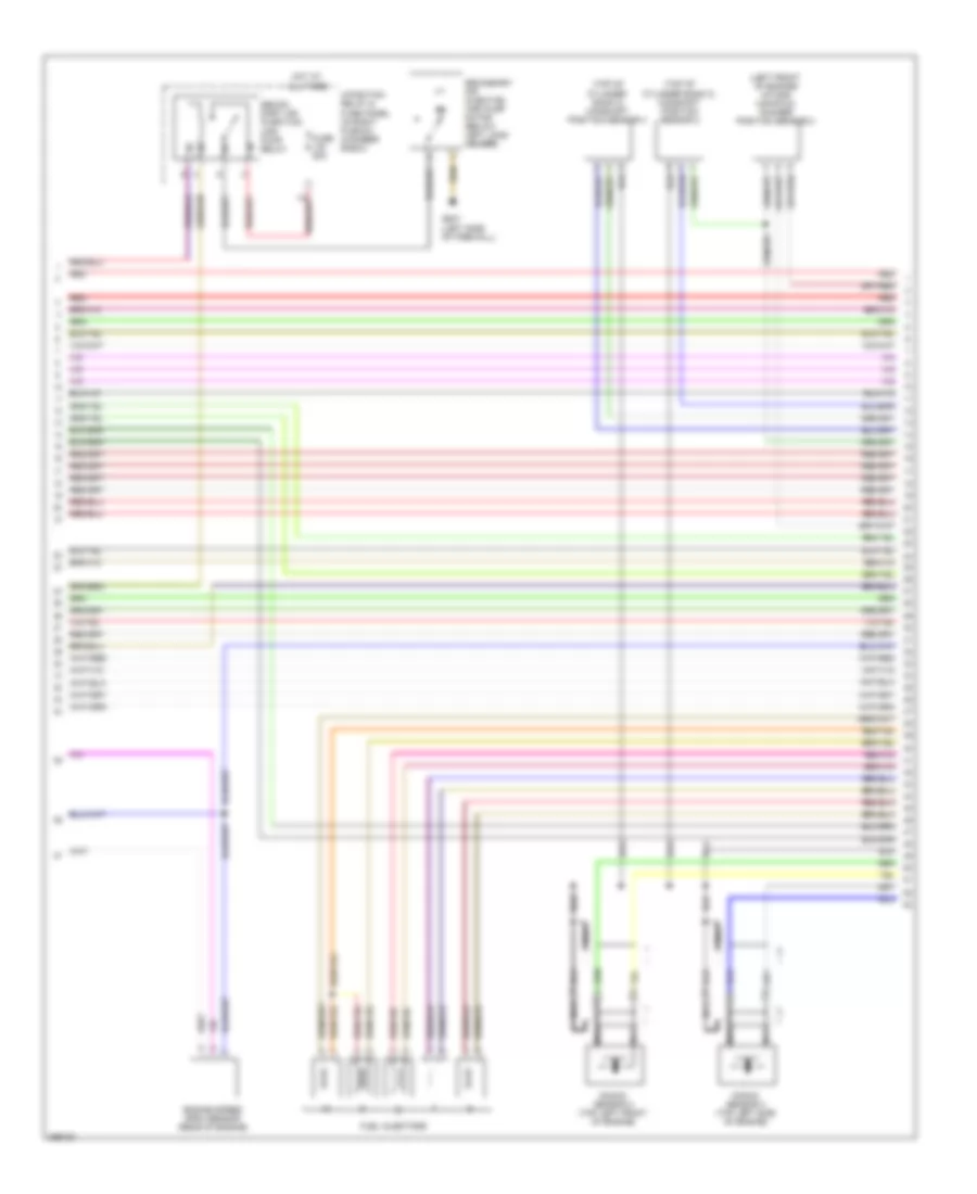
5.2L, Engine Performance Wiring Diagram (3 of 8) for Audi S6 Quattro 2007
List of elements for 5.2L, Engine Performance Wiring Diagram (3 of 8) for Audi S6 Quattro 2007:
- (rear of engine) engine coolant temperature (ect) sensor
- (right front of engine) intake manifold runner position sensor
- (right rear of engine compt) engine control module (ecm) i
- Computer data lines system
- Fuel injectors
- Fuel pressure sensor
- Knock sensor (ks) 1 (top right front of engine)
- Knock sensor (ks) 2 (top right side of engine)
- Nca
- Partial
- Red
- Starting/ charging system
- T94a
- Throttle valve control module (top left side of engine)
5.2L, Engine Performance Wiring Diagram (4 of 8) for Audi S6 Quattro 2007
List of elements for 5.2L, Engine Performance Wiring Diagram (4 of 8) for Audi S6 Quattro 2007:
- 14a
- 2a red
- Engine control module (ecm) i (right rear of engine compt)
- Fuse 10a
- Fuse 15a
- Fuse 30a
- Fuse 5a
- Fuse panel a
- Fuse panel b
- Hot at all times
- Red
- T60a
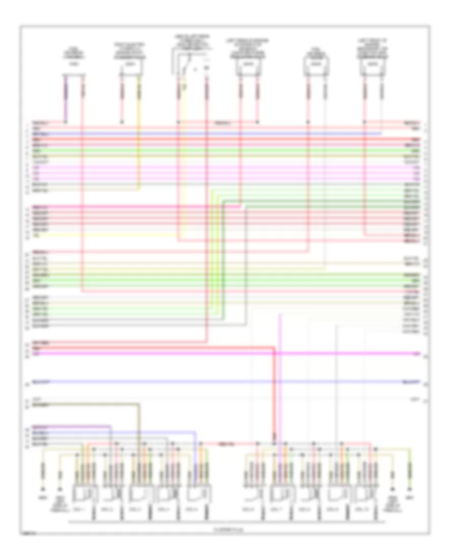
5.2L, Engine Performance Wiring Diagram (5 of 8) for Audi S6 Quattro 2007
List of elements for 5.2L, Engine Performance Wiring Diagram (5 of 8) for Audi S6 Quattro 2007:
- (above left rear wheelwell) leak detection pump (ldp)
- (left front of engine) secondary air injection (sir) solenoid valve
- (left rear of engine) evaporative emission canister purge regulator valve
- Coil 1
- Coil 10
- Coil 2
- Coil 3
- Coil 4
- Coil 5
- Coil 6
- Coil 7
- Coil 8
- Coil 9
- Fuel metering valve
- Fuel metering valve 2
- G600
- G601
- G645 (left side of firewall)
- G647 (left side of firewall)
- Nca
- Red
- Right electro- hydraulic engine mount solenoid valve
- To spark plug
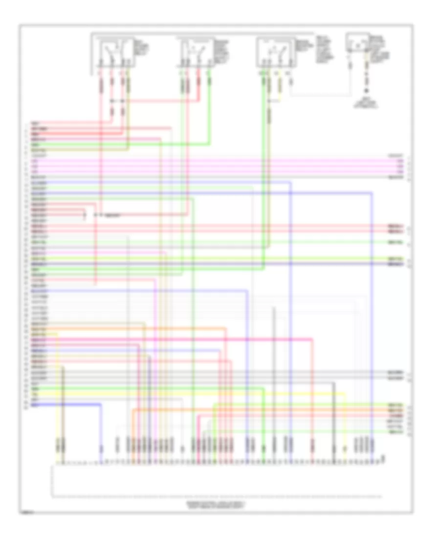
5.2L, Engine Performance Wiring Diagram (6 of 8) for Audi S6 Quattro 2007
List of elements for 5.2L, Engine Performance Wiring Diagram (6 of 8) for Audi S6 Quattro 2007:
- (left front of engine) intake manifold runner position sensor 2
- (top of cylinder bank 2) camshaft position sensor 2
- (top of cylinder bank 2) camshaft position sensor 4
- 4-position relay & fuse panel (in right plenum chamber e-box)
- Engine speed (rpm) sensor (rear of engine)
- Fuel injectors
- Fuse 50a
- G647 (left side of firewall)
- Hot at all times
- Knock sensor 3 (top left front of engine)
- Knock sensor 4 (top left side of engine)
- Nca
- Red
- Secon- dary air injection (air) pump relay
- Secondary air injection (air) pump motor (below left long- member)
5.2L, Engine Performance Wiring Diagram (7 of 8) for Audi S6 Quattro 2007
List of elements for 5.2L, Engine Performance Wiring Diagram (7 of 8) for Audi S6 Quattro 2007:
- Brake booster relay
- Brake system vacuum pump (left side of engine compt)
- Engine control module (ecm) ii (right rear of engine compt)
- G647 (left side of firewall)
- Red
- Relay holder (e-box) (in left plenum chamber e-box)
- T60b
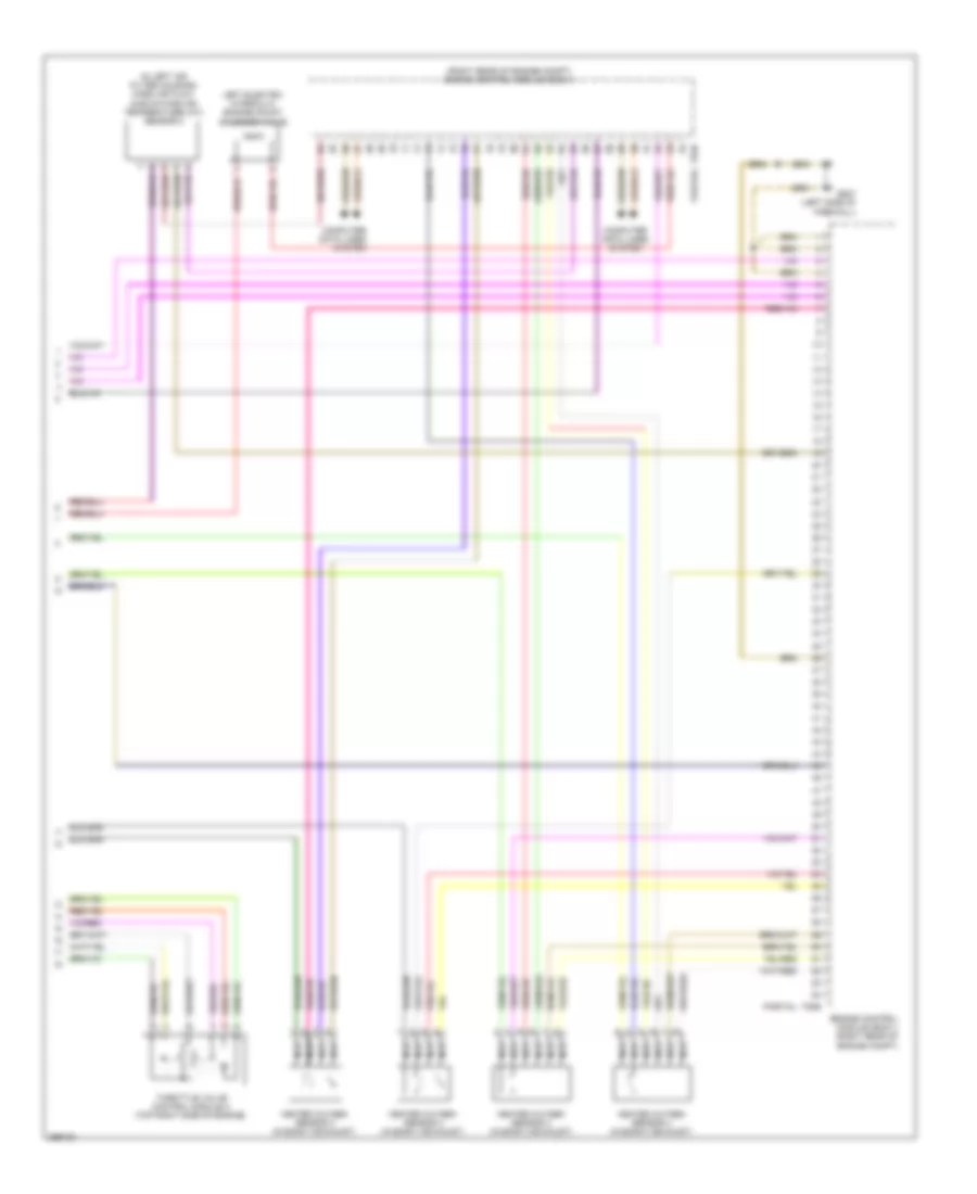
5.2L, Engine Performance Wiring Diagram (8 of 8) for Audi S6 Quattro 2007
List of elements for 5.2L, Engine Performance Wiring Diagram (8 of 8) for Audi S6 Quattro 2007:
- (in left air filter housing) mass air flow (maf)/intake air temperature (iat) sensor 2
- (right rear of engine compt) engine control module (ecm) ii
- Computer data lines system
- Engine control module (ecm) ii (right rear of engine compt)
- G647 (left side of firewall)
- Heated oxygen sensor 3 (in bank 3 exhaust)
- Heated oxygen sensor 4 (in bank 4 exhaust)
- Left electro- hydraulic engine mount solenoid valve
- Nca
- Partial
- T94b
- Throttle valve control module 2 (top right side of engine)