ENGINE PERFORMANCE
3.0L SC
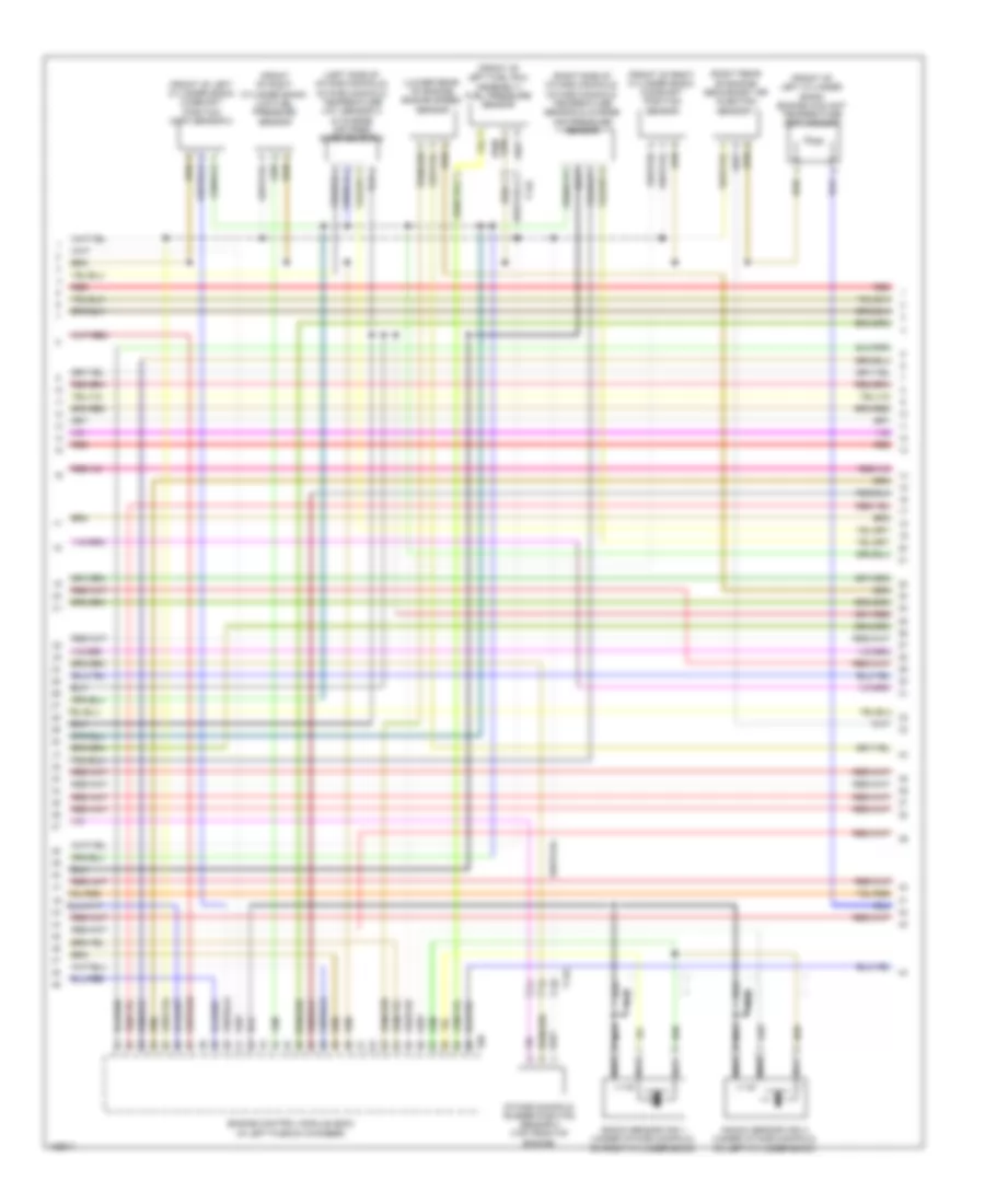
3.0L SC, Engine Performance Wiring Diagram (1 of 8) for Audi SQ5 Premium Plus 2014

List of elements for 3.0L SC, Engine Performance Wiring Diagram (1 of 8) for Audi SQ5 Premium Plus 2014:
- (left rear of engine compt) g12
- (left side of transmission) transmission control module (tcm)
- (right side of luggage compt) comfort system central control module
- 17a
- Accelerator pedal position sensor 1 & accelerator pedal position (app) sensor 2 (top of accelerator pedal assembly)
- Computer data lines system
- Cooling fans system
- Engine control module (in left plenum chamber)
- Fuse 10a
- Fuse 15a
- Fuse 5a
- Fuse carrier 1
- G12 (left rear of engine compt)
- Nca
- Oil level thermal sensor (in lower oil pan section)
- Oxygen sensor (02s) 2 after catalytic converter (twc) & oxygen sensor (o2s) 2 after catalytic converter heater (in left exhaust, behind three way catalytic converter)
- Oxygen sensor (o2s) after three way catalytic converter (twc) & oxygen sensor (o2s) 1 after catalytic converter heater (in right exhaust, behind three way catalytic converter)
- Red
- Relay/ fuse panel b (driver's side plenum chamber on electronics box)
- Starting/ charging system
- Starting/charging system
- T14g
- T16r
- T17e
- T17q
- T17r
- T32d
- T94
- Transmissions system
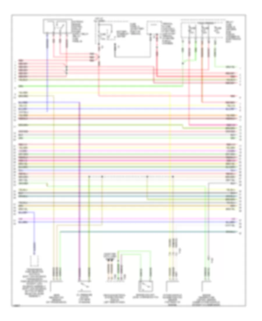
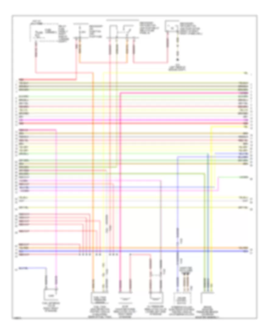
3.0L SC, Engine Performance Wiring Diagram (2 of 8) for Audi SQ5 Premium Plus 2014
List of elements for 3.0L SC, Engine Performance Wiring Diagram (2 of 8) for Audi SQ5 Premium Plus 2014:
- 10a
- 14a
- Battery interrupt igniter
- Computer data lines system
- Engine coolant level warning switch
- Engine temperature control sensor (under intake manifold, on right cylinder bank)
- Fuse 10a
- Fuse 110a
- Fuse 15a
- Fuse 20a
- Fuse carrier 1
- Fuse panel a (on battery positive terminal)
- Gear recognition sensor (on transmission)
- Hot at all times
- Intake manifold runner position sensor (top front of engine)
- Oil pressure switch (top rear of engine)
- Red
- Relay/ fuse panel b (driver's side plenum chamber on electronics box)
- T14g
- T16b
- T32b
- Terminal 30 wire junction 2 w/ battery jump start terminal (in center plenum chamber)
- Transmission park selector switch & shift lock solenoid (transmission park selector switch: on shift lock solenoid assembly) (shift lock solenoid: bottom of gear selector lever assembly)
- Vehicle electrical system control module (left side of dash)
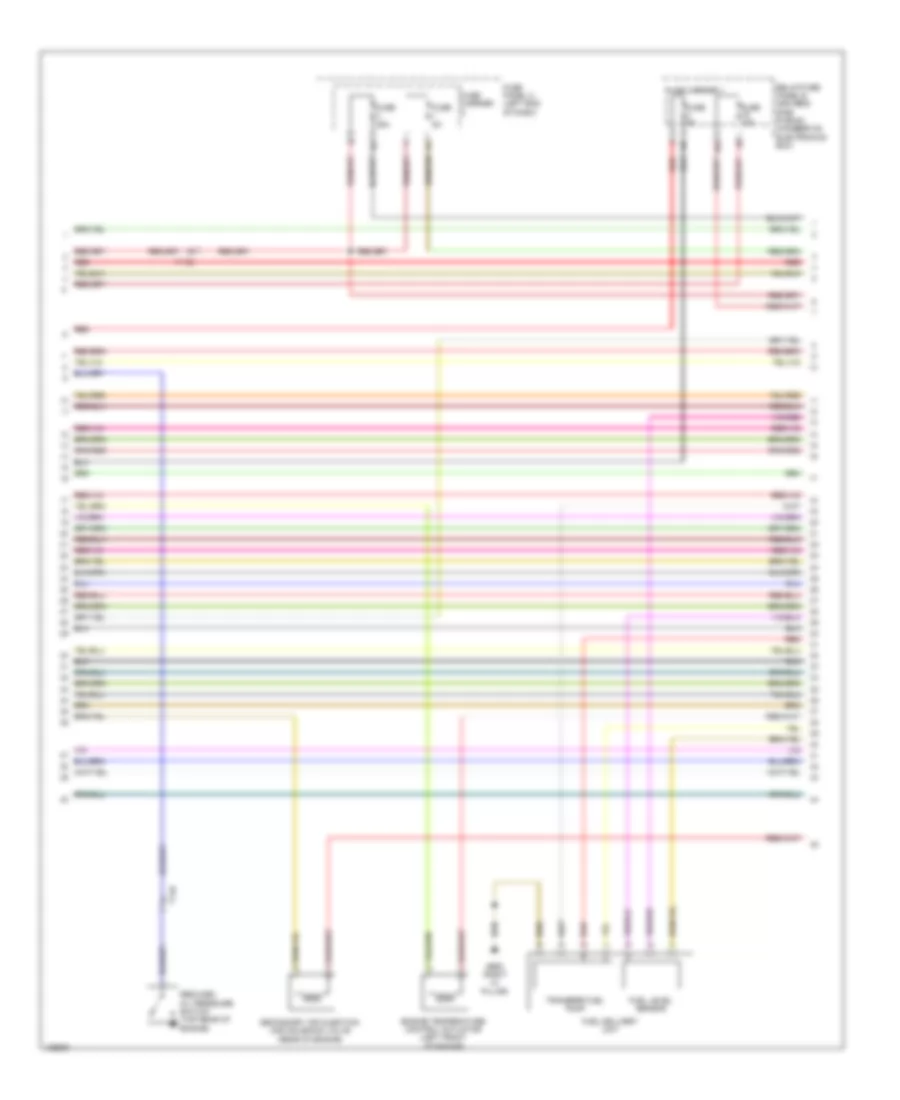
3.0L SC, Engine Performance Wiring Diagram (3 of 8) for Audi SQ5 Premium Plus 2014
List of elements for 3.0L SC, Engine Performance Wiring Diagram (3 of 8) for Audi SQ5 Premium Plus 2014:
- 16a
- Engine temperature control actuator (left front of engine)
- Fuel delivery unit
- Fuel level sensor
- Fuse 15a
- Fuse 25a
- Fuse 5a
- Fuse carrier
- Fuse carrier 1
- Fuse panel c (left end of dash)
- G663 (right "c" pillar)
- Red
- Reduced oil pressure switch (top rear of engine)
- Relay/fuse panel b (driver's side plenum chamber on electronics box)
- Secondary air injection (air) solenoid valve (rear of engine)
- T14e
- T17q
- Transfer fuel pump
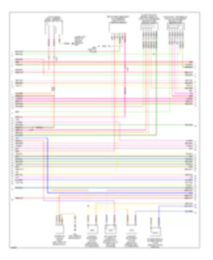
3.0L SC, Engine Performance Wiring Diagram (4 of 8) for Audi SQ5 Premium Plus 2014
List of elements for 3.0L SC, Engine Performance Wiring Diagram (4 of 8) for Audi SQ5 Premium Plus 2014:
- (below right rear seat, on underbody) fuel pump (fp) control module
- (in exhaust, upstream of catalytic converter) heated oxygen sensor (h02s)
- (in left exhaust, before three way catalytic converter) heated oxygen sensor (ho2s) 2
- (top of brake pedal assembly) brake lamp switch
- (under left front of center console) g687
- Camshaft adjustment valve 1 (exhaust) (rear of right cylinder bank)
- Camshaft adjustment valve 2 (exhaust) (rear of left cylinder bank)
- Charge air cooling pump (left front of engine compt)
- G12 (left rear of engine compt)
- G663 (right "c" pillar)
- Intake manifold runner control valve (rear of intake manifold)
- Left electro- hydraulic engine mount solenoid valve (left side of engine)
- Nca
- Red
- T17e
- T17q
- T17r
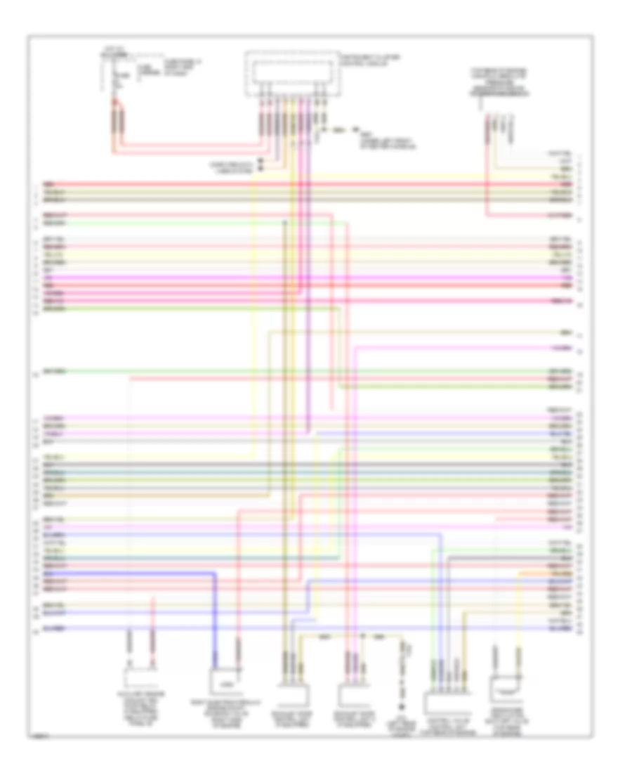
3.0L SC, Engine Performance Wiring Diagram (5 of 8) for Audi SQ5 Premium Plus 2014
List of elements for 3.0L SC, Engine Performance Wiring Diagram (5 of 8) for Audi SQ5 Premium Plus 2014:
- (top rear of engine) manifold absolute pressure sensor/intake air temperature sensor
- Auxiliary engine coolant (ec) pump relay (if equipped) (relay/fuse panel b)
- Computer data lines system
- Control valve control unit (top rear of engine)
- Crankcase ventilation shut-off valve (top rear of engine)
- Exhaust door control unit (if equipped)
- Exhaust door control unit 2 (if equipped)
- Fuse 5a
- Fuse carrier
- Fuse panel d (right end of dash)
- G12 (left rear of engine compt)
- G687 (under left front of center console)
- Hot at all times
- Instrument cluster control module
- Red
- Right electrohydraulic engine mount solenoid valve (right side of engine)
- T17g
- T17q
3.0L SC, Engine Performance Wiring Diagram (6 of 8) for Audi SQ5 Premium Plus 2014
List of elements for 3.0L SC, Engine Performance Wiring Diagram (6 of 8) for Audi SQ5 Premium Plus 2014:
- (front of left cylinder bank) camshaft position (cmp) sensor 2
- (front of left cylinder bank) engine coolant temperature (ect) sensor
- (front of left fuel rail assembly) fuel pressure sensor
- (front of right cylinder bank) camshaft position sensor
- (front of right cylinder bank) low fuel pressure sensor
- (left side of intake manifold) intake manifold temperature (iat) sensor 2 & charge air pres- sure sensor 2
- (lower rear of engine) engine speed sensor
- (right rear of engine) secondary air injection sensor 1
- (right side of intake manifold) intake manifold temperature sensor & charge air pressure sensor
- Engine control module (ecm) (in left plenum chamber)
- Intake manifold runner position sensor 2 (top front of engine)
- Knock sensor (ks) 1 (under intake manifold, on right cylinder bank)
- Knock sensor (ks) 2 (under intake manifold, on left cylinder bank)
- Nca
- Red
- T14e
- T14g
- T60
3.0L SC, Engine Performance Wiring Diagram (7 of 8) for Audi SQ5 Premium Plus 2014
List of elements for 3.0L SC, Engine Performance Wiring Diagram (7 of 8) for Audi SQ5 Premium Plus 2014:
- 12a
- 50a
- Brake booster pressure sensor (on brake booster assembly)
- Computer data lines system
- Cruise control switch
- Evap canister purge regulator valve 1 (right rear of engine)
- Fuel metering valve (right front of engine)
- Fuel tank leak detection control module (if equipped) (rear of fuel tank)
- Fuel tank pressure sensor
- Fuse 5a
- Fuse carrier 2
- G12 (left rear of engine compt)
- Hot at all times
- Oil pressure regulation valve (lower left side of engine)
- Red
- Relay/ fuse panel f (right side of luggage compt)
- Secondary air injection (air) pump fuse
- Secondary air injection (air) pump motor (front of right front wheelwell)
- Secondary air injection (air) pump relay (relay/fuse panel b)
- Steering column electronic systems control module (on steering column)
- T14e
- T16f
- T17b
- T17q
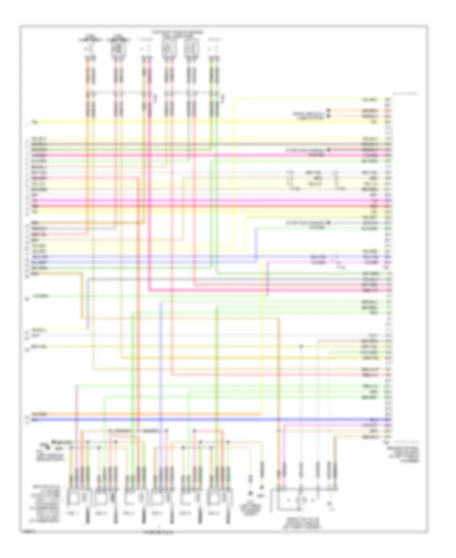
3.0L SC, Engine Performance Wiring Diagram (8 of 8) for Audi SQ5 Premium Plus 2014
List of elements for 3.0L SC, Engine Performance Wiring Diagram (8 of 8) for Audi SQ5 Premium Plus 2014:
- (top right side of engine) fuel injectors
- Coil 1
- Coil 2
- Coil 3
- Coil 4
- Coil 5
- Coil 6
- Computer data lines system
- Engine control module (ecm) (in left plenum chamber)
- Fuel injectors 5
- Fuel injectors 6
- G12 (left rear of engine compt)
- G600
- G601
- Ignition coils w/ power output stage (coil 1, 2 & 3: top of right cylinder bank) (coil 4, 5 & 6: top of left cylinder bank)
- Nca
- Red
- Starting/charging system
- T14e
- T14g
- T17e
- T17q
- T17r
- T60
- T94
- Throttle valve control module (on throttle body)
- To spark plug