ENGINE PERFORMANCE
3.0L TURBO
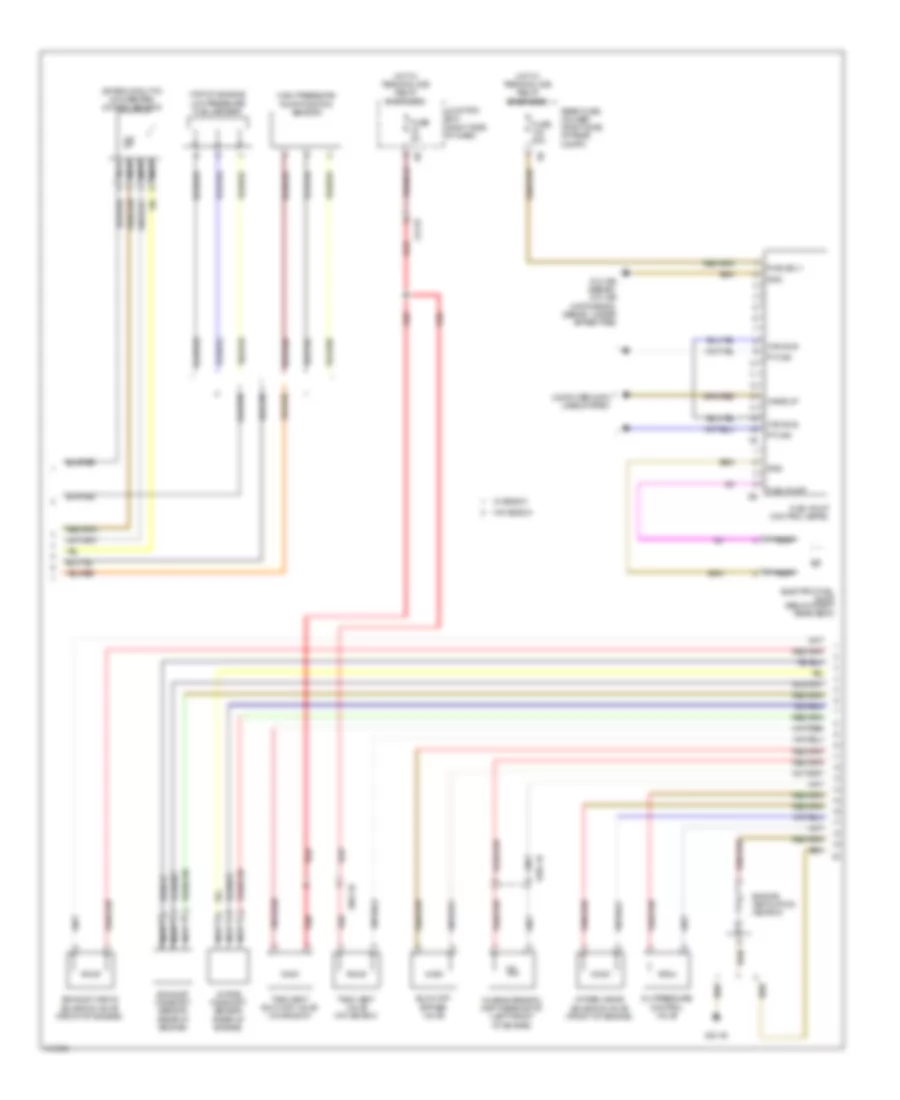
3.0L Turbo, Engine Performance Wiring Diagram (1 of 5) for BMW 535i GT 2013

List of elements for 3.0L Turbo, Engine Performance Wiring Diagram (1 of 5) for BMW 535i GT 2013:
- (before catalytic converter) oxygen sensor
- (right side of engine) knock sensor
- Act activation
- Bsd bus sig
- Bsd sig
- Coolant pump
- Cooling fans system
- Crankshaft position sensor (left rear side of engine)
- Digital motor electronics (dme) control module (right rear engine compt)
- Elec throttle act gnd
- Elec throttle act sig
- Electromotive throttle actuator
- Intake air temperature pressure sensor (right side of engine)
- Intake manifold pressure sensor (right side of engine)
- Knock sens sig
- Nca
- Oil level sensor (bottom of oil pan)
- Quantity control valve
- Sens gnd
- Sens sig
- Sens sply
- Sply
- Starting/charging system
- Vlv activation
- Vlv sply
- Wastegate valve pressure converter
- X671 2b
- Zero gear sensor (m/t)
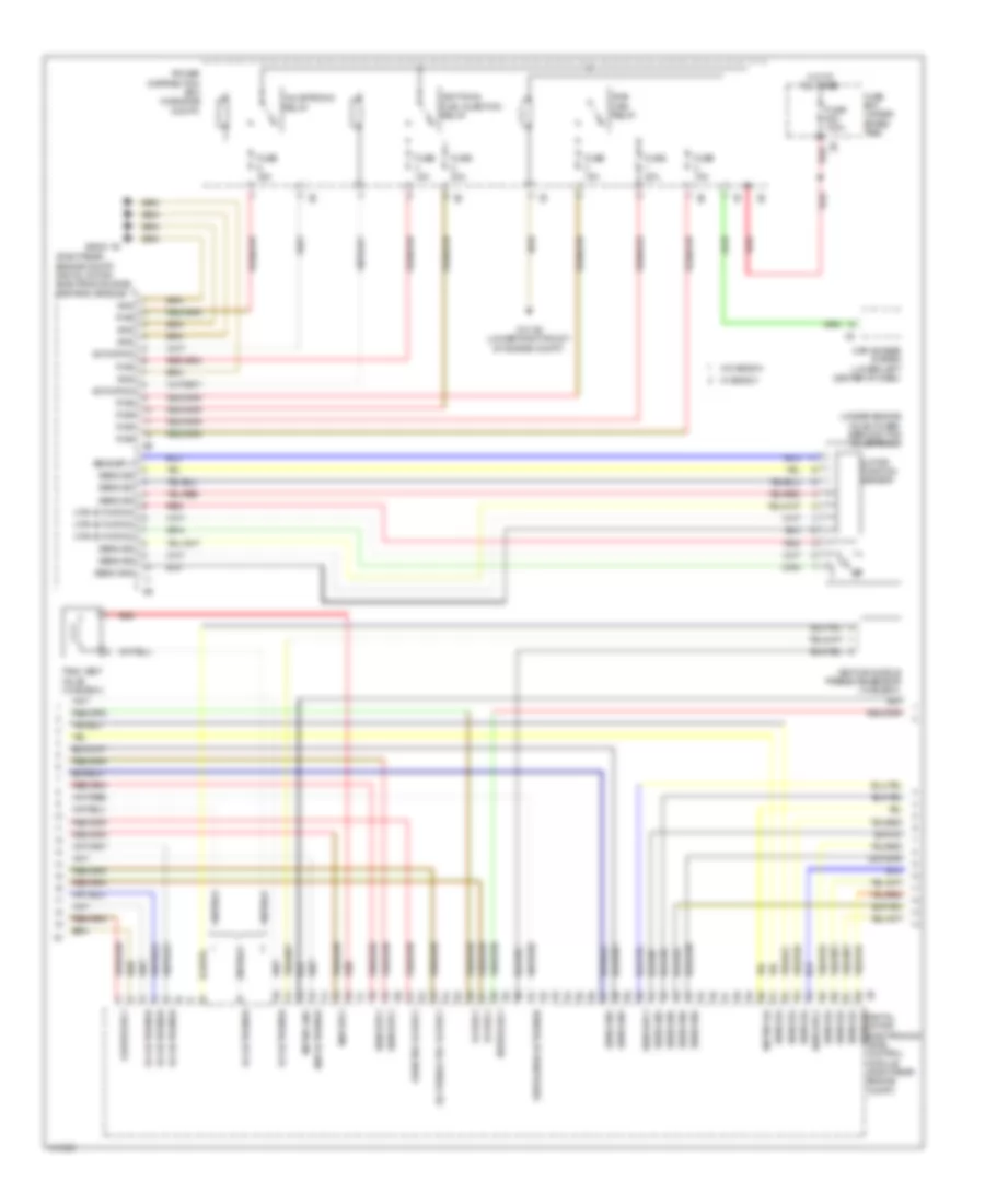
3.0L Turbo, Engine Performance Wiring Diagram (2 of 5) for BMW 535i GT 2013
List of elements for 3.0L Turbo, Engine Performance Wiring Diagram (2 of 5) for BMW 535i GT 2013:
- (after catalytic converter) oxygen sensor
- (top of engine) low pressure fuel sensor
- Blow off bypass valve
- Can bus
- Characteristic map thermostat (left front of engine)
- Computer data lines system
- Electric fuel pump (below right rear seat)
- Engine ventilation heating
- Exhaust camshaft sensor (rear of engine)
- Exhaust vanos solenoid valve (front of engine)
- Fuel pump
- Fuel pump control (ekps)
- Fuse 20a
- Fuse 5a
- Gnd
- High pressure pump position sensor
- Hot w/ terminal 30b relay energized
- Intake camshaft sensor (rear of engine)
- Intake vanos solenoid valve (front of engine)
- Junction box (right side of dash)
- Nca
- Oil pressure control valve
- Pt can
- Pwr sply
- Rear fuse holder (right side of rear compt)
- Red
- Tank vent shut-off valve (w/o bosch)
- Tank vent valve (w/o bosch)
- W/ bosch
- W/o bosch
- Wake up
- X13 1b
- X664 1b
- X705 1b
- Z10 16b (sedan) z10 18b (hatchback) (sedan: under spare tire)
- Z23 1b
3.0L Turbo, Engine Performance Wiring Diagram (3 of 5) for BMW 535i GT 2013
List of elements for 3.0L Turbo, Engine Performance Wiring Diagram (3 of 5) for BMW 535i GT 2013:
- (right rear engine compt) digital motor electronics (dme) control module
- (under engine valve cover) servomotor valvetronic
- Activation
- Car access system (lower left center of dash)
- Diverter vlv sply
- Dme main relay
- Fuse 100a
- Fuse 15a
- Fuse 20a
- Fuse 40a
- Fuse box (under spare tire)
- Gnd
- Heater sply
- Hot at all times
- Ignition & fuel injection relay
- Map activation
- Map sply
- Meter gnd
- Meter sig
- Meter sply
- Motor position sensor
- Mtr activation
- Oil press ctrl vlv sply
- Power distribution box (in engine compt)
- Pwr
- Red
- Sens gnd
- Sens sig
- Sens sig digital motor electronics (dme) control module (right rear engine compt)
- Sens sply
- Tank vent valve (w/ bosch)
- Valvetronic relay
- Ventilation activation
- Venturi nozzle pressure sensor (w/ bosch)
- Vlv activation
- Vlv sply
- W/ bosch
- W/o bosch
- Z10 3b (lower right front of engine compt)
- Z6000 1b
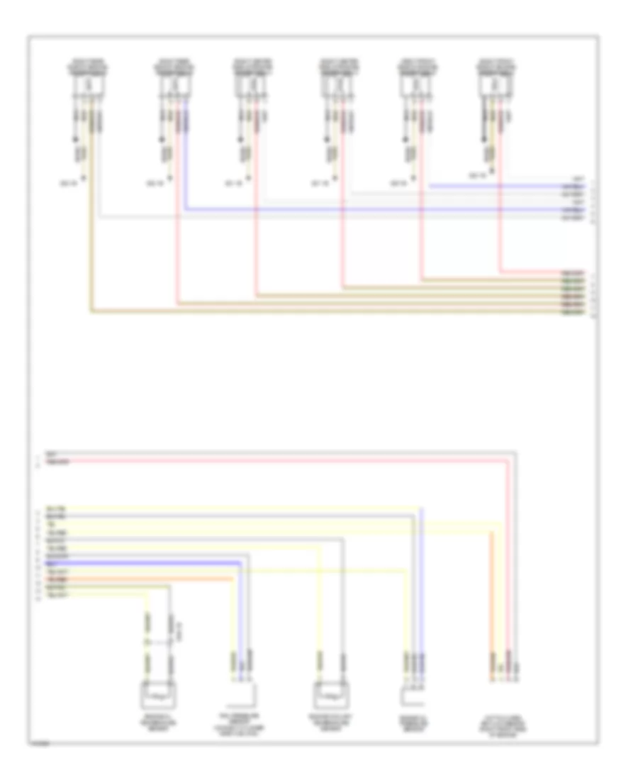
3.0L Turbo, Engine Performance Wiring Diagram (4 of 5) for BMW 535i GT 2013
List of elements for 3.0L Turbo, Engine Performance Wiring Diagram (4 of 5) for BMW 535i GT 2013:
- (right center side of engine) ignition coil 3
- (right center side of engine) ignition coil 4
- (right front side of engine) ignition coil 1
- (right front side of engine) ignition coil 2
- (right rear side of engine) ignition coil 5
- (right rear side of engine) ignition coil 6
- Engine coolant temperature sensor
- Engine oil pressure sensor
- Engine oil temperature sensor
- Hot film mass air flow sensor (right front side of engine)
- Nca
- Plug spark
- Rail pressure sensor (on right cylinder head fuel rail)
- Spark plug
- X704 1b
- Z20 1b
- Z21 1b
- Z22 1b
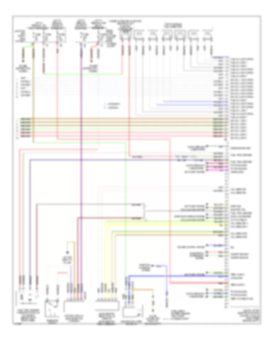
3.0L Turbo, Engine Performance Wiring Diagram (5 of 5) for BMW 535i GT 2013
List of elements for 3.0L Turbo, Engine Performance Wiring Diagram (5 of 5) for BMW 535i GT 2013:
- (top of engine) fuel injectors
- (under intake air colector) engine mount electric changeover valve
- 11b
- A248 1b
- Accelerator pedal module (part of acceleration pedal assembly)
- Anti-theft system
- Car bus sig
- Computer data lines system
- Cooling fans system
- Cruise control system
- Cut-out relay
- Dc/dc converter
- Diagnosis socket
- Digital motor electronics (dme) control module (right rear engine compt)
- Electric fan
- Electronic suspension system
- Flexray bus sig
- Fuel inj 1 activation
- Fuel inj 1 sply
- Fuel inj 2 activation
- Fuel inj 2 sply
- Fuel inj 3 activation
- Fuel inj 3 sply
- Fuel inj 4 activation
- Fuel inj 4 sply
- Fuel inj 5 activation
- Fuel inj 5 sply
- Fuel inj 6 activation
- Fuel inj 6 sply
- Fuel tank leakage
- Fuel tank leakage diagnostic module (w/o bosch) (behind right rear wheel)
- Fuse 15a
- Fuse 5a
- Hall sens gnd
- Hall sens sig
- Hall sens sply
- Hot w/ terminal 15n relay energized
- Hot w/ terminal 30b relay energized
- Hot w/ terminal 30g relay energized
- Ign coil 1 activation
- Ign coil 1 sply
- Ign coil 2 activation
- Ign coil 2 sply
- Ign coil 3 activation
- Ign coil 3 sply
- Ign coil 4 activation
- Ign coil 4 sply
- Ign coil 5 activation
- Ign coil 5 sply
- Ign coil 6 activation
- Ign coil 6 sply
- Intelligent battery sensor (right side of rear compt)
- Junction box (right side of dash)
- Lin bus sig
- Natural vacuum leak detection (w/ bosch)
- Nca
- Pnk
- Power distribution system
- Pressure switch
- Pt-can bus sig
- Radiator shutter drive unit
- Rear fuse holder (right side of rear compt)
- Red
- Sig
- Start sig
- Starting/ charging system
- Starting/charging system
- Term 15 sply
- Term 15 wake up sig
- Term 30 sply
- W/ bosch
- W/o bosch
- X13 12b
- X148 1b
- X671 3b
- Z10 13b (right "c" pillar)
- Z10 2b (lower left front of engine compt)