ENGINE PERFORMANCE
4.4L
4.4L, Engine Performance Wiring Diagram (1 of 4) for BMW 540i 1998

List of elements for 4.4L, Engine Performance Wiring Diagram (1 of 4) for BMW 540i 1998:
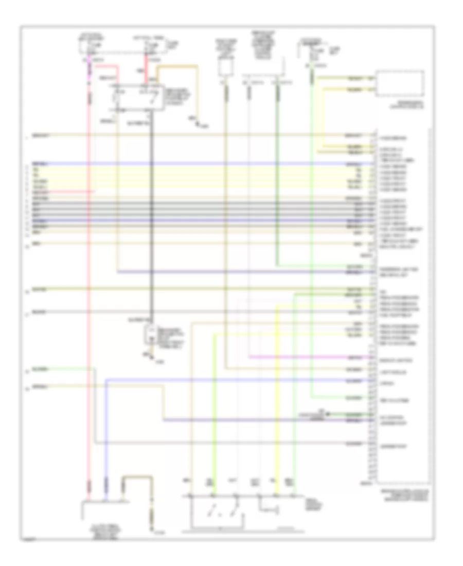
4.4L, Engine Performance Wiring Diagram (2 of 4) for BMW 540i 1998
List of elements for 4.4L, Engine Performance Wiring Diagram (2 of 4) for BMW 540i 1998:
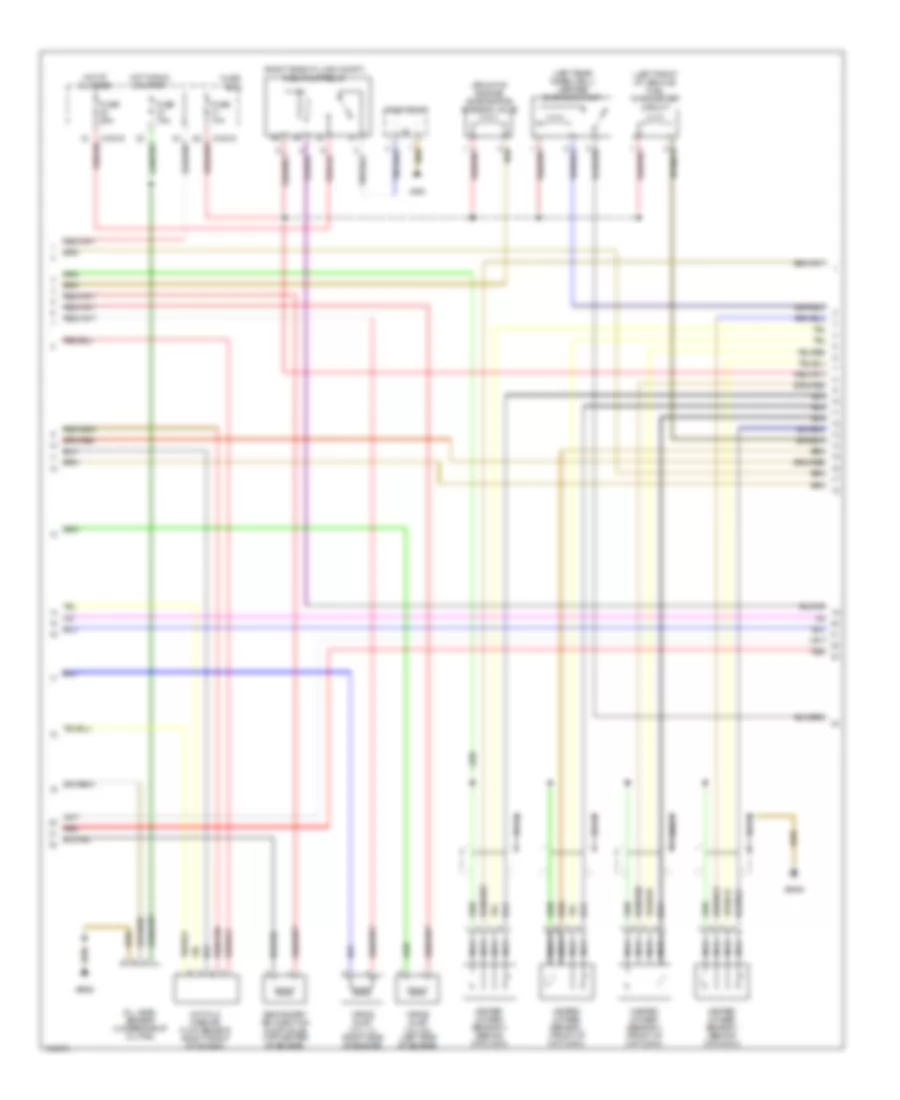
4.4L, Engine Performance Wiring Diagram (3 of 4) for BMW 540i 1998
List of elements for 4.4L, Engine Performance Wiring Diagram (3 of 4) for BMW 540i 1998:
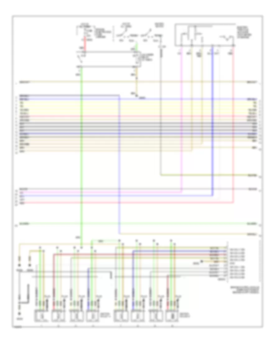
4.4L, Engine Performance Wiring Diagram (4 of 4) for BMW 540i 1998
List of elements for 4.4L, Engine Performance Wiring Diagram (4 of 4) for BMW 540i 1998: