ENGINE PERFORMANCE
4.8L
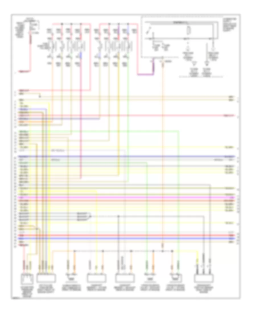
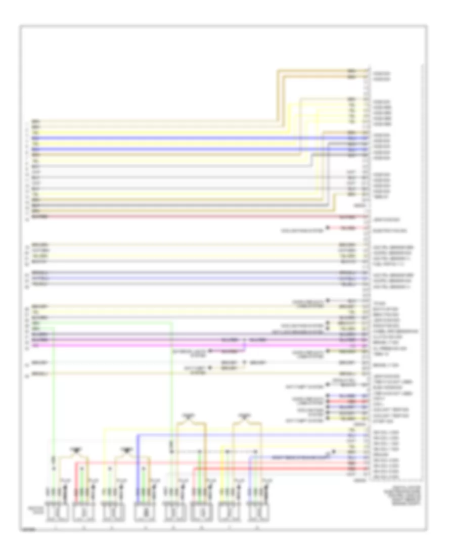
4.8L, Engine Performance Wiring Diagram (1 of 6) for BMW 650i 2007

List of elements for 4.8L, Engine Performance Wiring Diagram (1 of 6) for BMW 650i 2007:
- Bsd sig
- Camshaft 1 sig
- Camshaft 2 sig
- Camshaft sensor 2 - exhaust (rear of engine)
- Camshaft sensor 2 - intake (rear of engine)
- Can sig
- Computer data lines system
- Coolant temp sig
- Crankshaft sig
- Digital motor electronics (dme) control module (right rear of engine compt)
- Dme relay 1
- Engine coolant temperature sensor
- Fuel tank sig
- Fuel tank vent valve (top of engine)
- Fuse 20a
- Fuse 30a
- Ground
- Individual control intake system valve
- Inj 1 sig
- Inj 2 sig
- Inj 3 sig
- Inj 4 sig
- Inj 5 sig
- Inj 6 sig
- Inj 7 sig
- Inj 8 sig
- Intake pipe sig
- Knock sens 1 sig
- Knock sens 2 sig
- Maf sens sig
- Map thermo sig
- Red
- Term 30
- Term 87
- Throttle actuator
- Throttle sig
- To dme rly 2 (diagram 2 of 6)
- To ign coil rly (diagram 5 of 6)
- Txd sig
- Vanos solenoid valve 2 - exhaust (front of engine)
- Vanos solenoid valve 2 - intake (front of engine)
- Vanos val 1 sig
- Vanos val 2 sig
- Var intake pos
- Var intake sig
- Vvt mod sig
- X13701
- X13844
- X6 (right rear of engine compt)
- X60001
- X60003
- X60092
- X60093
- X60094
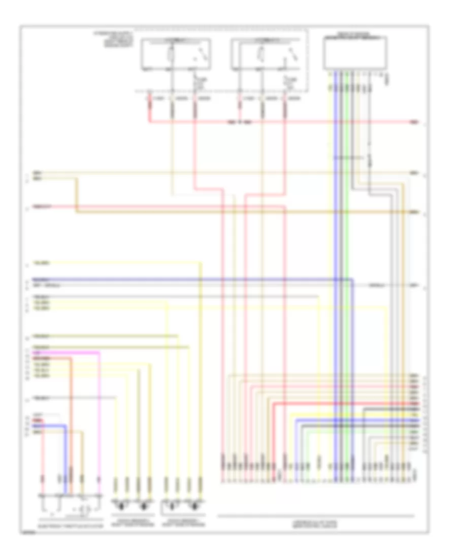
4.8L, Engine Performance Wiring Diagram (2 of 6) for BMW 650i 2007
List of elements for 4.8L, Engine Performance Wiring Diagram (2 of 6) for BMW 650i 2007:
- Camshaft sensor 1 - exhaust (rear of engine)
- Camshaft sensor 1 - intake (rear of engine)
- Characteristic map thermostat (front of engine)
- Crankshaft position sensor (right side of engine)
- Dme relay 2
- From dme relay 1 (diagram 1 of 6)
- From dme rly 1 (diagram 1 of 6)
- Front fuse holder (under right side of dash)
- Fuel injection valves
- Fuse 20a
- Fuse 30a
- Fuse 60a
- Hot at all times
- Hot film air mass meter (right front of engine compt)
- Intake pipe pressure sensor (front of engine)
- Nca
- Red
- To dme rly 3 (diagram 4 of 6)
- Vanos solenoid valve 1 - exhaust (front of engine)
- Vanos solenoid valve 1 - intake (front of engine)
- X60093
4.8L, Engine Performance Wiring Diagram (3 of 6) for BMW 650i 2007
List of elements for 4.8L, Engine Performance Wiring Diagram (3 of 6) for BMW 650i 2007:
- (rear of engine) eccentric shaft sensor 2
- Electronic throttle actuator
- Fuse 40a
- Knock sensor 1 (right side of engine)
- Knock sensor 2 (right side of engine)
- Nca
- Red
- Variable valve timing gear control module
- Vvt relay 1
- Vvt relay 2
- X10681
- X60093
- X60095
- X60211
- X60212
- X60223
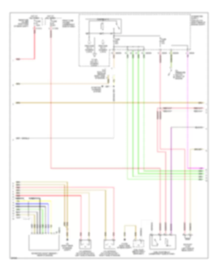
4.8L, Engine Performance Wiring Diagram (4 of 6) for BMW 650i 2007
List of elements for 4.8L, Engine Performance Wiring Diagram (4 of 6) for BMW 650i 2007:
- Dme relay 3
- Eccentric shaft sensor 1 (rear of engine)
- Exhaust flap (left side of rear compt)
- From dme rly 2 (diagram 2 of 6)
- Front fuse holder (under right side of dash)
- Fuel pump (below right rear seat)
- Fuel pump relay (under right side of dash)
- Fuse 100a
- Fuse 10a
- Fuse 20a
- Fuse 30a
- Hot at all times
- Nca
- Oil pressure switch (front of engine)
- Oil quality sensor (right side of engine)
- Rear fuse holder (right side of rear compt)
- Red
- Starting/ charging system
- To ign coil rly (diagram 5 of 6)
- Valvetronic actuator motor 1 (right side of engine)
- Valvetronic actuator motor 2 (left side of engine)
- X11014 red
- X13792 (right side of rear compt)
- X6 (right rear of engine compt)
- X6009
- X60093
- X60094
- X60213
4.8L, Engine Performance Wiring Diagram (5 of 6) for BMW 650i 2007
List of elements for 4.8L, Engine Performance Wiring Diagram (5 of 6) for BMW 650i 2007:
- (left side of dash) brake light switch
- (under left side of dash) clutch switch module
- Accelerator pedal module (part of accel pedal assembly)
- Anti-theft system
- Car access system (under left side of dash)
- E-box fan
- From dme rly 3 (diagram 5 of 6)
- From ivm (diagram 1 of 6)
- Fuel tank leakage diagnosis module (behind right rear wheel)
- Fuse 20a
- Heated oxygen sensor i (before cat conv)
- Heated oxygen sensor i (behind cat conv)
- Heated oxygen sensor ii (before cat conv)
- Heated oxygen sensor ii (behind cat conv)
- Ignition coil unloader relay
- Nca
- X10318
- X13787 (left front floor)
- X6009
- X60091
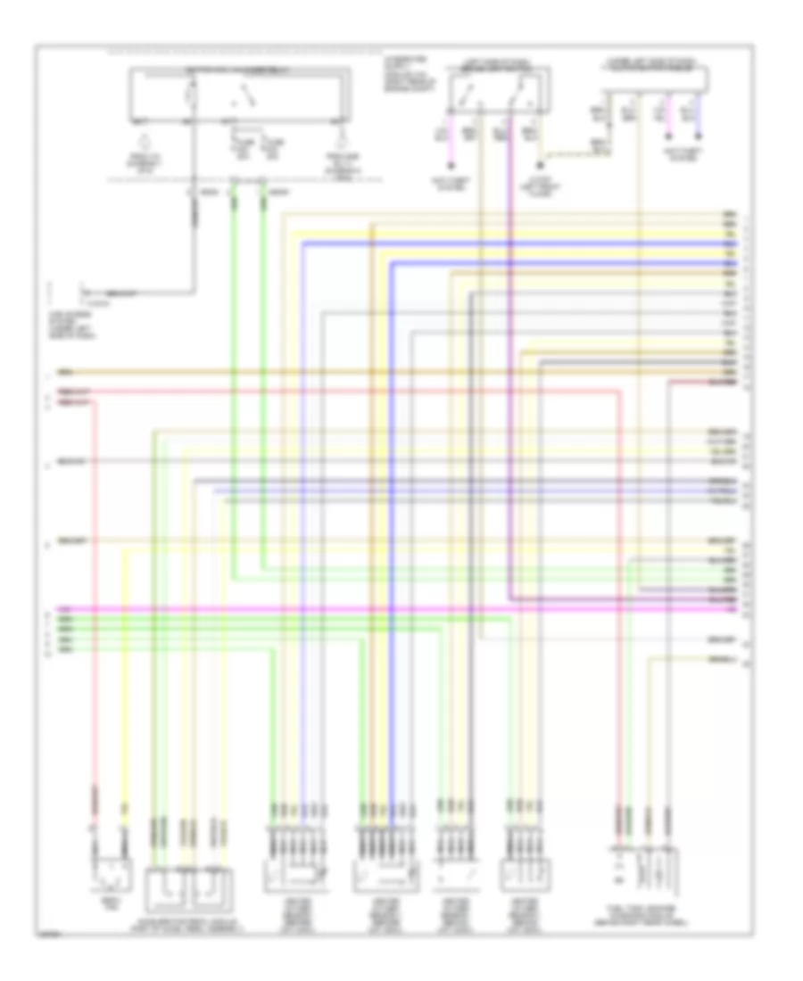
4.8L, Engine Performance Wiring Diagram (6 of 6) for BMW 650i 2007
List of elements for 4.8L, Engine Performance Wiring Diagram (6 of 6) for BMW 650i 2007:
- (ter 31-32 not used)
- (ter 34-35 not used)
- Acc pdl sensor (+)
- Acc pdl sensor grd
- Accpdl sensor sig
- Anti-lock brakes system
- Anti-theft system
- Brake lt sig
- Can h
- Can l
- Clutch sw sig
- Computer data lines system
- Coolant temp sig
- Cooling fans system
- Digital motor electronics (dme) control module (right rear of engine compt)
- Ebox fan sig
- Elec immob sig
- Electric fan sig
- Exh flap sig
- Exterior lights system
- Fuel pmp rly (+)
- Ground
- Ho2s grd
- Ho2s sig
- Ign coil 1 sig
- Ign coil 2 sig
- Ign coil 3 sig
- Ign coil 4 sig
- Ign coil 5 sig
- Ign coil 6 sig
- Ign coil 7 sig
- Ign coil 8 sig
- Ignition coils
- Leak diag sig
- Nca
- Oil press sw sig
- Plug
- Radiator sig
- Red
- Start sig
- Td sig
- Term 15
- Term 87
- Wheel spd sensor sig
- X6 (right rear of engine compt)
- X60002
- X60004
- X60005
- X64561
- X64562
- X64563
- X64564