ENGINE PERFORMANCE
4.4L TWIN TURBO
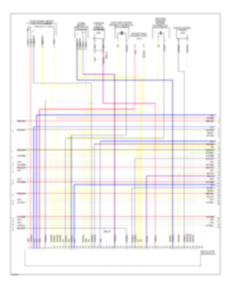
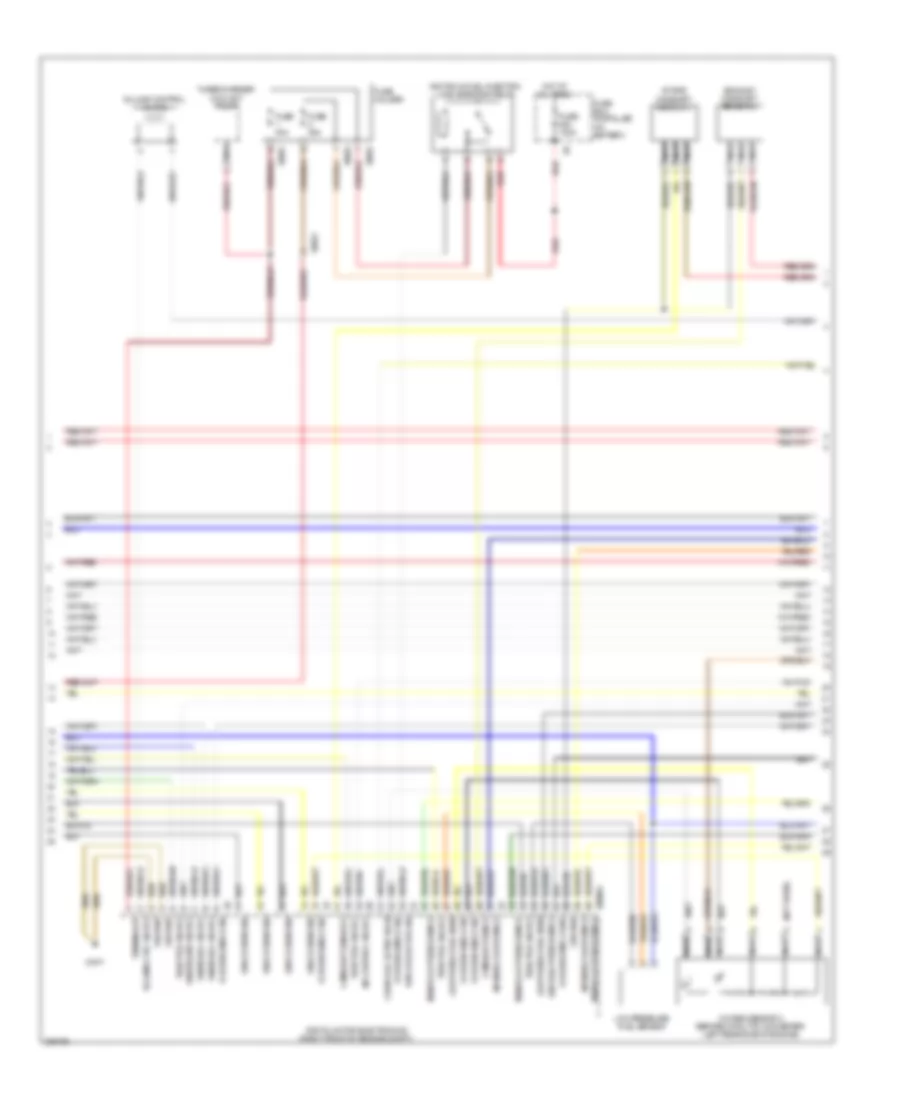
4.4L Twin Turbo, Engine Performance Wiring Diagram, A/T (1 of 11) for BMW 650i 2012

List of elements for 4.4L Twin Turbo, Engine Performance Wiring Diagram, A/T (1 of 11) for BMW 650i 2012:
- (right rear of luggage compt)
- (top right side of fuel tank) natural vacuum leak detection
- 11b
- Car access system (w/o automatic gearbox)
- Clutch module
- Computer data lines system
- Cooling fans system
- Dc/dc converter (under left side of luggage compt)
- Digital motor electronics (right front of engine compt)
- Early production
- Fuse 10a
- Fuse 5a
- Hot at all times
- Hot w/ bistable relay energized
- Hot w/ terminal 30b relay energized
- Ignition coils cylinder (ignition coils 1, 2, 3 & 4: on right cylinder bank) (ignition coils 5 & 6: on left cylinder bank)
- Junction box (under right side of dash)
- Late production
- Nca
- Pressure switch
- Rear fuse holder
- Red
- Spark plug
- Z10 13b (right "c" pillar)
- Z10 9b (left kick panel)
- Z6000 1b
- Z6000 2b (left front of engine compt)
- Z6000 3b right front of engine compt
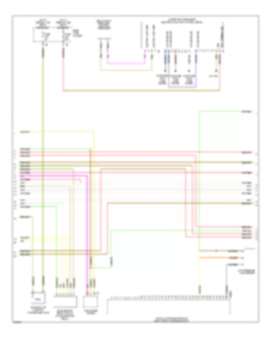
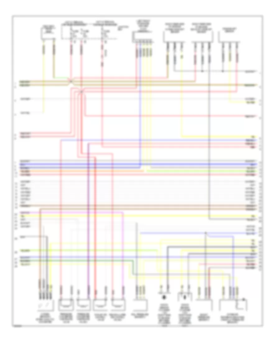
4.4L Twin Turbo, Engine Performance Wiring Diagram, A/T (2 of 11) for BMW 650i 2012
List of elements for 4.4L Twin Turbo, Engine Performance Wiring Diagram, A/T (2 of 11) for BMW 650i 2012:
- (at accelerator pedal)
- (below right rear seat) electric fuel pump
- (under right rear seat) electric fuel pump control (ekps)
- Accelerator pedal module
- Car access system
- Computer data lines system
- Digital motor electronics (right front of engine compt)
- Electric fuel pump
- Exhaust flap electric changeover valve
- Fuse 20a
- Fuse 5a
- Gnd
- Hot w/ terminal 15n relay energized
- Hot w/ terminal 30b relay energized
- Low pressure fuel sensor
- Nca
- Pt-can bus sig
- Rear fuse holder
- Sply, terminal 30b
- X60004
- Z10 18b
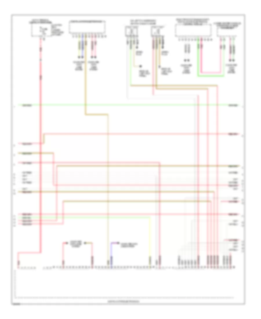
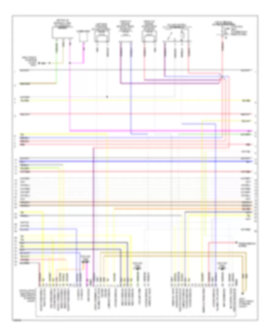
4.4L Twin Turbo, Engine Performance Wiring Diagram, A/T (3 of 11) for BMW 650i 2012
List of elements for 4.4L Twin Turbo, Engine Performance Wiring Diagram, A/T (3 of 11) for BMW 650i 2012:
- (on left cylinder bank)
- (right front of engine compt) digital motor electronics control module
- (under center console) integrated chassis management
- Computer data lines system
- Digital motor electronics 2
- Fuse 10a
- Hot w/ terminal 30b relay energized
- Ignition coils cylinder
- Junction box (under right side of dash)
- Nca
- Pnk
- Red
- Spark plug
- Z6000 4b (left kick panel)
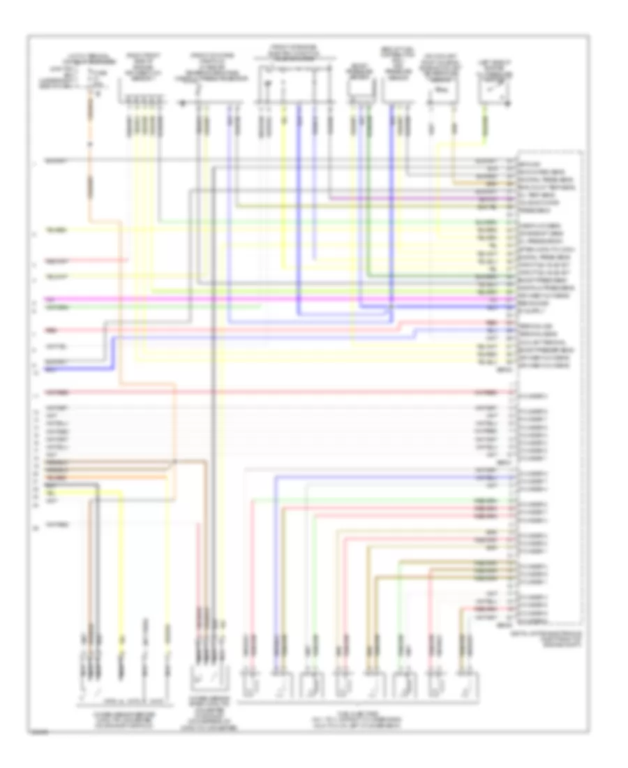
4.4L Twin Turbo, Engine Performance Wiring Diagram, A/T (4 of 11) for BMW 650i 2012
List of elements for 4.4L Twin Turbo, Engine Performance Wiring Diagram, A/T (4 of 11) for BMW 650i 2012:
- (cylinders 1 & 2: right side of engine) knock sensor
- (cylinders 3 & 4: right side of engine) knock sensor
- (end of fuel-distribution rail) rail pressure sensor
- (in exhaust, downstream of catalytic converter) oxygen sensor after catalytic converter
- (in oil reservoir) oil level sensor
- (in right plenum box) quantity control valve
- (left side of engine) oil pressure switch
- (on exhaust manifold) oxygen sensor before catalytic converter
- Digital motor electronics (right front of engine compt)
- Nca
- Red
- Starting/ charging system
- Wastegate valve pressure converter
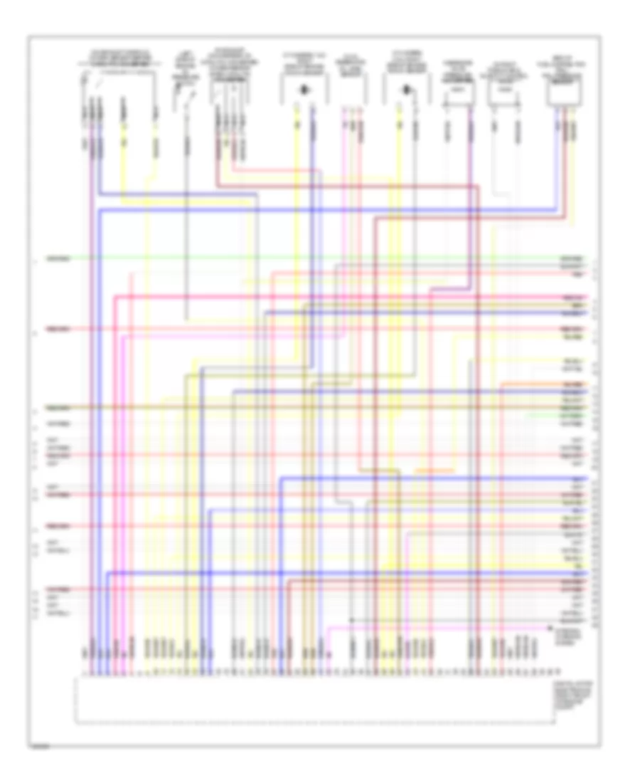
4.4L Twin Turbo, Engine Performance Wiring Diagram, A/T (5 of 11) for BMW 650i 2012
List of elements for 4.4L Twin Turbo, Engine Performance Wiring Diagram, A/T (5 of 11) for BMW 650i 2012:
- (front of engine)
- (left front of engine) exhaust vanos solenoid valve
- (lower front of engine) crankshaft sensor
- (on manual transmission) (w/o automatic gearbox) zero gear sensor
- Charging pressure sensor
- Digital motor electronics (right front of engine compt)
- Electric throttle valve actuator
- Front of intake manifold intake air temperature/ manifold pressure sensor
- Red
- X60002
- X60004
- X697 1b
4.4L Twin Turbo, Engine Performance Wiring Diagram, A/T (6 of 11) for BMW 650i 2012
List of elements for 4.4L Twin Turbo, Engine Performance Wiring Diagram, A/T (6 of 11) for BMW 650i 2012:
- (right side of engine, between cylinders 5 & 6) knock sensor
- (right side of engine, between cylinders 7 & 8) knock sensor
- Digital motor electronics 2
- Exhaust vanos solenoid valve 2
- Nca
- Oxygen sensor 2 after catalytic converter
- Oxygen sensor 2 before catalytic converter
- Quantity control valve 2
- Red
- Wastegate valve 2 pressure converter
- X698 1b
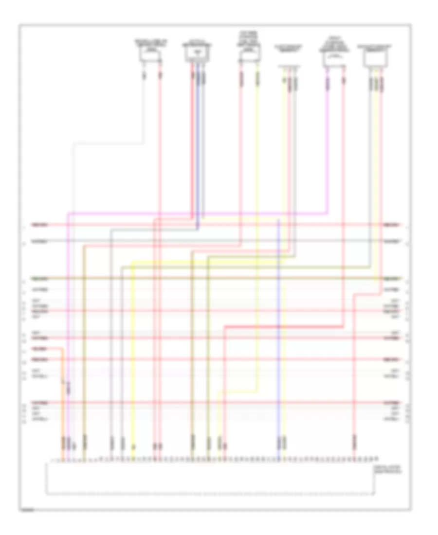
4.4L Twin Turbo, Engine Performance Wiring Diagram, A/T (7 of 11) for BMW 650i 2012
List of elements for 4.4L Twin Turbo, Engine Performance Wiring Diagram, A/T (7 of 11) for BMW 650i 2012:
- Charging pressure sensor 2
- Digital motor electronics (right front of engine compt)
- Digital motor electronics 2
- Electric throttle valve actuator 2
- Intake air temperature/ manifold pressure sensor 2
- Motor position sensor
- Rail pressure sensor 2
- Red
- Valvetronic actuator motor (right side of engine)
- Valvetronic servomotor 2
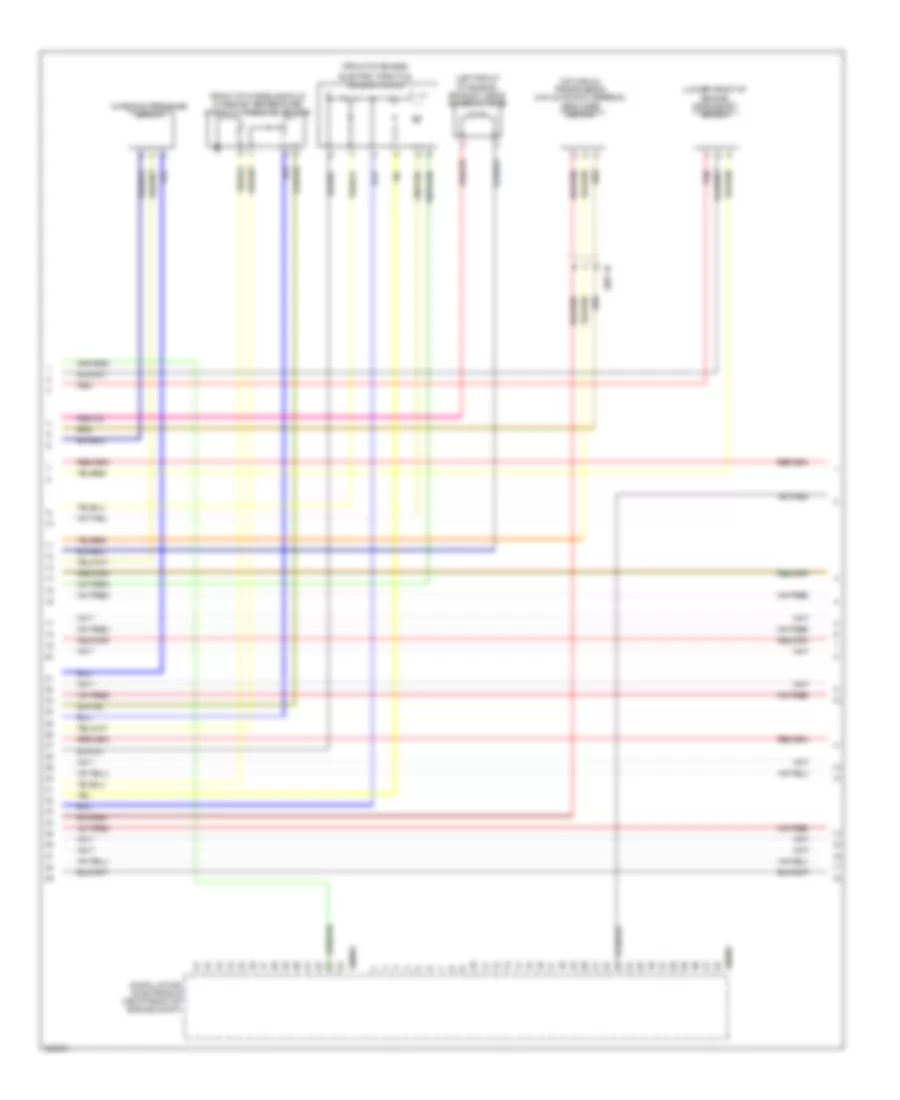
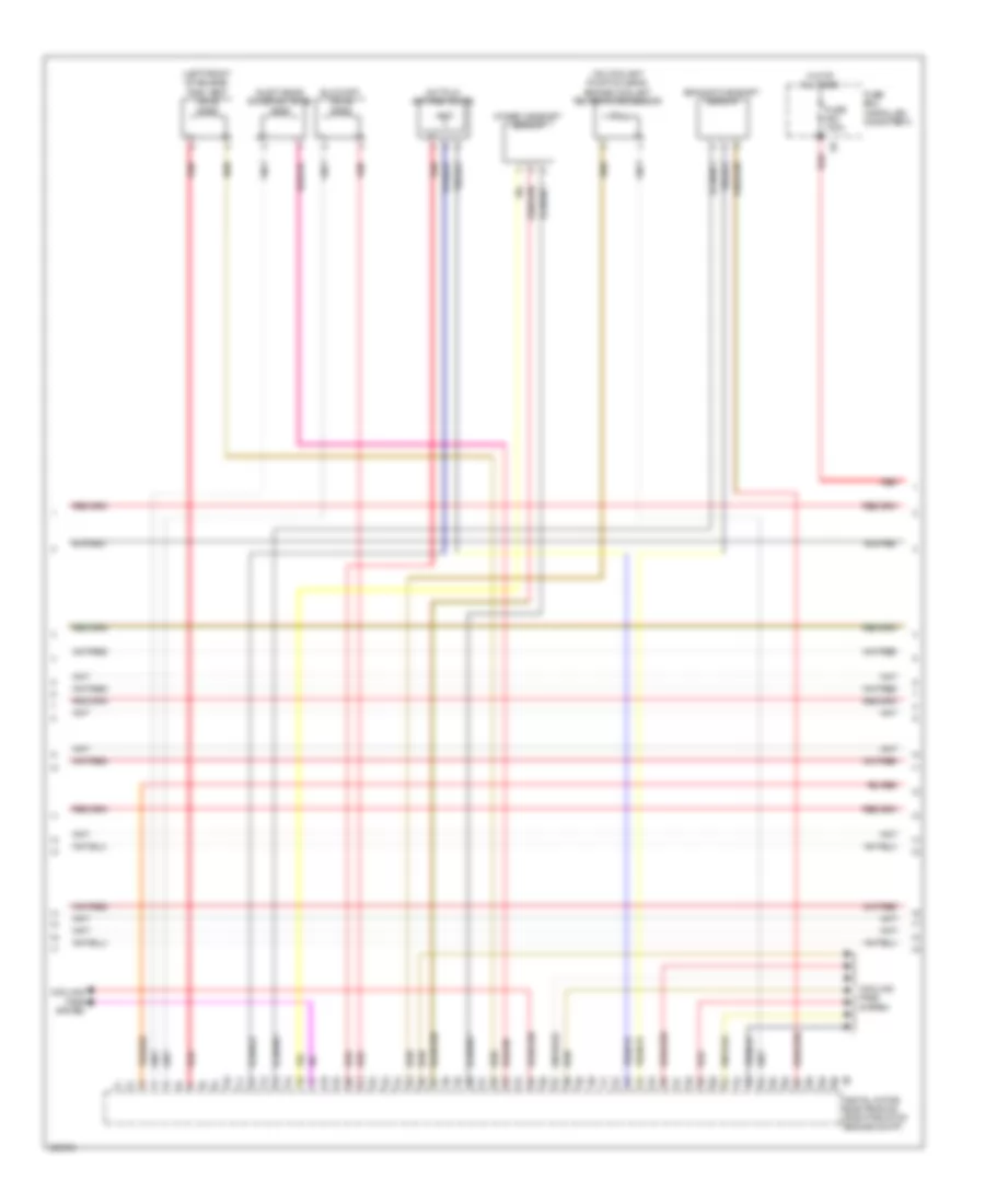
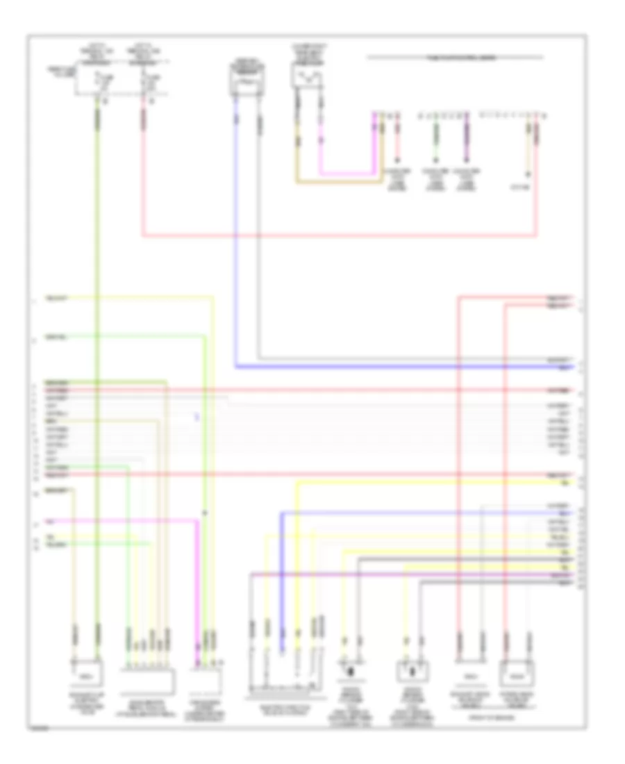
4.4L Twin Turbo, Engine Performance Wiring Diagram, A/T (8 of 11) for BMW 650i 2012
List of elements for 4.4L Twin Turbo, Engine Performance Wiring Diagram, A/T (8 of 11) for BMW 650i 2012:
- (left front of engine) tank vent valve
- (on coolant pump housing) engine coolant temperature sensor
- Blow-off valve
- Cooling fans system
- Digital motor electronics (right front of engine compt)
- Exhaust camshaft sensor
- Fuse 100a
- Fuse box (installed on battery)
- Hot at all times
- Hot film air mass meter
- Inlet vanos solenoid valve
- Intake camshaft sensor
- Red
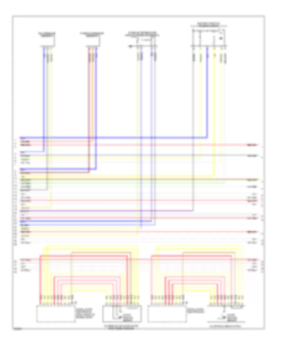
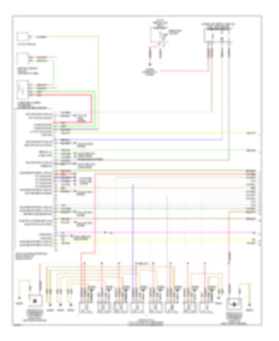
4.4L Twin Turbo, Engine Performance Wiring Diagram, A/T (9 of 11) for BMW 650i 2012
List of elements for 4.4L Twin Turbo, Engine Performance Wiring Diagram, A/T (9 of 11) for BMW 650i 2012:
- Car access system
- Digital motor electronics (right side of engine compt)
- Digital motor electronics 2
- Dme main relay
- Fuse 10a
- Fuse 15a
- Fuse 20a
- Fuse 40a
- Power distribution
- Red
- Relay for ignition & fuel injection relay
- Valvetronic relay
- Z10 3b (right front of engine compt)
- Z6000 5b
- Z6000 6b
4.4L Twin Turbo, Engine Performance Wiring Diagram, A/T (10 of 11) for BMW 650i 2012
List of elements for 4.4L Twin Turbo, Engine Performance Wiring Diagram, A/T (10 of 11) for BMW 650i 2012:
- (front of engine) intake vanos solenoid valve 2
- (top rear of engine) fuel tank vent valve 2
- Digital motor electronics 2
- Exhaust camshaft sensor 2
- Hot film air mass meter 2
- Inlet camshaft sensor 2
- Recirculated air control valve 2
- Red
- X698 1b
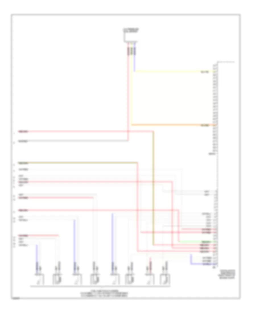
4.4L Twin Turbo, Engine Performance Wiring Diagram, A/T (11 of 11) for BMW 650i 2012
List of elements for 4.4L Twin Turbo, Engine Performance Wiring Diagram, A/T (11 of 11) for BMW 650i 2012:
- Digital motor electronics (right front of engine compt)
- Fuel injection cylinders (cylinders 1, 2, 3 & 4: on right cylinder bank) (cylinders 5, 6, 7 & 8: on left cylinder bank)
- Low pressure fuel sensor
- X60002
4.4L Twin Turbo, Engine Performance Wiring Diagram, M/T (1 of 6) for BMW 650i 2012
List of elements for 4.4L Twin Turbo, Engine Performance Wiring Diagram, M/T (1 of 6) for BMW 650i 2012:
- (under left rear of vehicle) fuel tank leakage diagnostic module
- Accelerator pedal module
- Activation solenoid
- Cas bus sig
- Central gateway module (left end of dash)
- Clutch module
- Clutch module sig
- Computer data lines system
- Cooling fans system
- Digital motor electronics (right front of engine compt)
- Electric changeover valve
- Electric fan activation
- Flexray bus sig
- Fuse 5a
- Gnd temperature sens
- Hot w/ terminal 30b relay energized
- Ignition coils (1 to 4: on right cylinder bank) (5 to 8: on left cylinder bank)
- Ignition coils interference suppression capacitor (right side of engine)
- Ignition coils interference suppression capacitor 2 (left side of engine)
- Integrated chassis management (under center console)
- Lin bus sig
- Nca
- Pnk
- Power distribution system
- Pt-can bus sig
- Rear fuse holder
- Red
- Sig diagnostic module
- Spark plug
- Speed sig
- Start sig
- Temperature sensor sig
- Terminal 15
- Transmissions system
- Wake-up sig
- X64561
- X64562
- X64563
- X64564
4.4L Twin Turbo, Engine Performance Wiring Diagram, M/T (2 of 6) for BMW 650i 2012
List of elements for 4.4L Twin Turbo, Engine Performance Wiring Diagram, M/T (2 of 6) for BMW 650i 2012:
- (front of engine)
- (under right rear seat) electric fuel pump
- Accelerator pedal module (at accelerator pedal)
- Car access system (under center of rear shelf)
- Computer data lines system
- Electric throttle valve actuator 2
- Exhaust flap electric changeover valve
- Exhaust vanos solenoid valve 2
- Fuel pump control (ekps)
- Fuse 20a
- Fuse 5a
- Gear box temperature sensor
- Hot w/ terminal 15n relay energized
- Hot w/ terminal 30b relay energized
- Intake vanos solenoid valve 2
- Knock sensor cylinder 5 & 6 (right side of engine, between cylinders 5 & 6)
- Knock sensor cylinder 7 & 8 (right side of engine, between cylinders 7 & 8)
- Nca
- Rear fuse holder
- Red
- Z10 18b
4.4L Twin Turbo, Engine Performance Wiring Diagram, M/T (3 of 6) for BMW 650i 2012
List of elements for 4.4L Twin Turbo, Engine Performance Wiring Diagram, M/T (3 of 6) for BMW 650i 2012:
- (not used)
- Air control valve 2
- Air mass flow sens 2
- Camshaft sens 2
- Camshaft sensor 2
- Charcoal filter valve
- Digital motor electronics (right front of engine compt)
- Exhaust camshaft sensor 2
- Fuse 100a
- Fuse 30a
- Fuse box (installed on battery)
- Fuse holder
- Gnd rail press sens 2
- Ground
- Hot at all times
- Ign coils & fuel inj
- Ignition & fuel injection load shedding relay
- Intake camshaft sensor 2
- Knock sens sig
- Low press fuel sens
- Low pressure fuel sensor
- Manifold press sens 2
- Nca
- Oxygen sens 2 gnd
- Oxygen sens 2 sig
- Oxygen sensor 2 before catalytic converter (left rear side of engine)
- Red
- Terminal 87
- Throttle valve 2
- Turbocharger coolant pump
- Vanes sol valve 2
- Volume control valve 2
- Volume ctrl valve 2
- Wastegate valve 2
- X60004 manifold press sens 2
- X6053
- X7517
- X8682
- X8683
4.4L Twin Turbo, Engine Performance Wiring Diagram, M/T (4 of 6) for BMW 650i 2012
List of elements for 4.4L Twin Turbo, Engine Performance Wiring Diagram, M/T (4 of 6) for BMW 650i 2012:
- (left front of engine) air mass flow sensor 2
- (right rear side of engine) exhaust camshaft sensor
- (right rear side of engine) intake camshaft sensor
- Boost pressure sensor 2
- Crankshaft sensor
- Fuse 10a
- Fuse 20a
- Fuse 30a
- Hot w/ terminal 15n relay energized
- Hot w/ terminal 30b relay energized
- Intake air temperature/intake manifold pressure sensor 2
- Junction box
- Knock sensor cylinder 1 & 2 (right side of engine, between cylinders 1 & 2)
- Knock sensor cylinder 3 & 4 (right side of engine, between cylinders 3 & 4)
- Nca
- Oxygen sensor 2 after catalytic converter
- Pressure converter wastegate valve
- Pressure converter wastegate valve 2
- Rail pressure sensor 2
- Recirculated air control valve 2
- Red
- Tank vent valve
- Thrust air control valve
- X13 1b
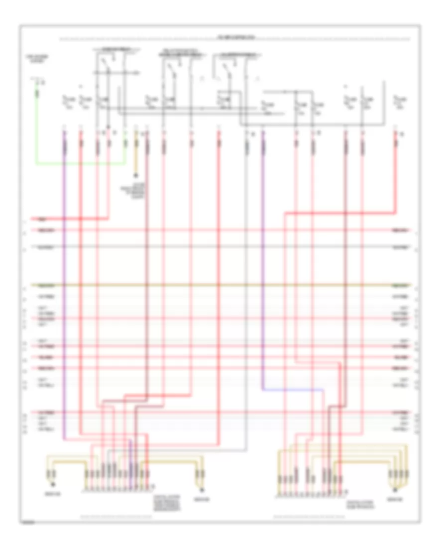
4.4L Twin Turbo, Engine Performance Wiring Diagram, M/T (5 of 6) for BMW 650i 2012
List of elements for 4.4L Twin Turbo, Engine Performance Wiring Diagram, M/T (5 of 6) for BMW 650i 2012:
- (bottom of engine oil pan) oil condition sensor
- (front of engine) exhaust vanos solenoid valve
- (front of engine) intake vanos solenoid valve
- (left side of engine) volume control valve
- (right front of engine compt) x7517
- Air control valve
- Alternator
- Boost press sens 2
- Bsd bus sig
- Camshaft sensor
- Coolant pump
- Cooling fans system
- Digital motor electronics (right front of engine compt)
- Fuse 30a
- Ground
- Hot w/ terminal 15n relay energized
- Junction box (under right side of dash)
- Knock sens sig
- Manifold press sens
- Map thermostat
- Mass flow sens 2
- Oxygen sens 2 sig
- Oxygen sens gnd
- Oxygen sens sig
- Rail press sens 2
- Red
- Throttle actr 2
- Throttle valve actr
- Transmissions system
- Vanes sol valve
- Volume control valves relay
- Volume ctrl valve
- Volume ctrl valves
- Wastegate valve
- X60002
- X60004
- X7517 (right front of engine compt)
4.4L Twin Turbo, Engine Performance Wiring Diagram, M/T (6 of 6) for BMW 650i 2012
List of elements for 4.4L Twin Turbo, Engine Performance Wiring Diagram, M/T (6 of 6) for BMW 650i 2012:
- (end of fuel- distribution rail) rail pressure sensor
- (front of engine) electric throttle valve actuator
- (front of intake manifold) intake air temperature/intake manifold pressure sensor
- (left side of engine) oil pressure switch
- (not used)
- (on coolant pump housing) engine coolant temperature sensor
- (right front side of engine) air mass flow sensor 1
- After catalytic conv
- Air mass flow sens
- Boost press sens
- Boost presser sens
- Boost pressure sensor
- Bsd bus sig
- Coolant terminal
- Crankshift sens
- Cylinder 1
- Cylinder 2
- Cylinder 3
- Cylinder 4
- Cylinder 5
- Cylinder 6
- Cylinder 7
- Cylinder 8
- Digital motor electronics (right front of engine compt)
- Eng colnt temp sens
- Fuel injectors (inj 1 to 4: on right cylinder bank) (inj 5 to 8: on left cylinder bank)
- Fuse 30a
- Gnd oxygen sens
- Gnd rail press sens
- Ground
- Hot w/ terminal 15n relay energized
- Junction box (under right side of dash)
- Manifold press sens
- Mass flow sens
- Nca
- Oil pressure sw
- Oil temp sens
- Oxygen sensor after catalytic converter (in exhaust, downstream of catalytic converter)
- Oxygen sensor before catalytic converter (on exhaust manifold)
- Press sens
- Red
- Sig rail press sens
- Terminal 30b
- Terminal sens
- Throttle valve act
- Valve actuator
- X60001
- X60002
- X60005